
3CFT9 BRS X - Basket FAGOR - Free user manual and instructions
Find the device manual for free 3CFT9 BRS X FAGOR in PDF.

| Product type | Decorative hood |
| Brand | Fagor |
| Model | 3CFT9 BRS X |
| Width | 90 cm (typical for this model) |
| Weight | Approximately 20 kg (estimate) |
| Power supply | 220-240 V, 50/60 Hz |
| Suction power | Up to 650 m³/h (estimate) |
| Speed levels | 3 + intensive (depending on model) |
| Lighting type | Halogen, 20W max (G4) |
| Grease filter | Metal, dishwasher safe |
| Charcoal filter | Washable or disposable (depending on version) |
| Filter saturation indicator | Yes (LED or display) |
| Timer function | Yes (5-20 minutes depending on speed) |
| Extraction version | Suction or recirculation (filtering) |
| Minimum distance to cooking surface | 50 cm (electric) / 65 cm (gas or mixed) |
| Air outlet diameter | 150 mm (estimate) |
| Maintenance | Clean regularly with a damp cloth |
| Repairability | Spare parts available via after-sales service |
| Standards | CE, compliant with WEEE directive |
Frequently Asked Questions - 3CFT9 BRS X FAGOR
User questions about 3CFT9 BRS X FAGOR
0 question about this device. Answer the ones you know or ask your own.
Ask a new question about this device
Download the instructions for your Basket in PDF format for free! Find your manual 3CFT9 BRS X - FAGOR and take your electronic device back in hand. On this page are published all the documents necessary for the use of your device. 3CFT9 BRS X by FAGOR.
USER MANUAL 3CFT9 BRS X FAGOR
| D MONTAGE- UND GEBRAUCHSANWEISUNG | |
| GB NSTRUCTION ON MOUNTING AND USE | |
| F PRESCRIPTIONS DE MONTAGE ET MODE D'EMPLOI | |
| NL MONTAGEVOORSCHRIFTEN EN GEBRUIKSAANWIJZING | |
| I ISTRUZIONI DI MONTAGGIO E D'USO | |
| E MONTAJE Y MODO DE EMPLEO | |
| P INSTRUÇÕES PARA MONTAGEM E UTILIZAÇÃO | |
| RU ИНСТРУКЦИИ ПО УСТАНОВКЕ И ПОЛЬЗОВАНИЮ | |
| CZ NÁVOD NA MONTÁŽ A POUŽITÍ |

natural_image
Line drawing of a 7-meter air conditioner unit with internal compartments and ventilation slots (no text or symbols)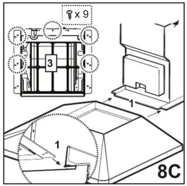
natural_image
Technical line drawing of a mechanical component with a 19R label, no readable text or symbols beyond the label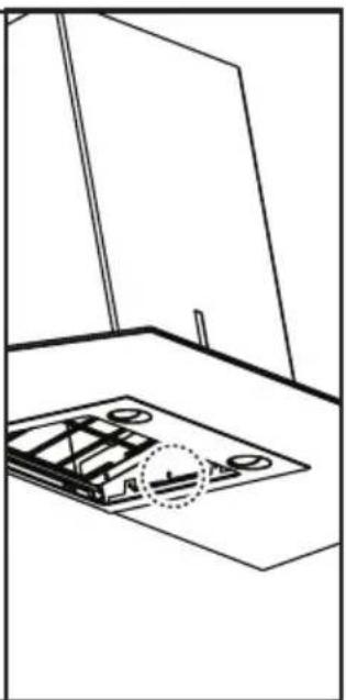
natural_image
Technical line drawing of a mechanical assembly with a base plate and mounting bracket (no text or symbols)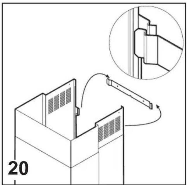
Consult the designs in the front pages referenced in the text by alphabet letters. Closely follow the instructions set out in this manual. All responsibility, for any eventual inconveniences, damages or fires caused by not complying with the instructions in this manual, is declined.
The cooker hood must be placed at a minimum distance of 50 cm from the cooking plane for electric cookers and 65cm for gas or mixed cookers. The hood can be installed above these heights but for optimum performance it should be installed at the distance quoted for the appropriate heat source.
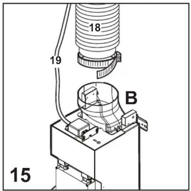
The hood is equipped with a top air outlet „B“ for discharge of fumes to the outside (Ducting version – exhaust pipe and pipe fixing clamps not provided).
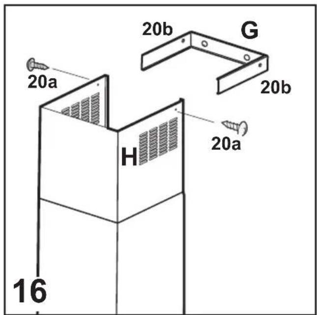
Should it not be possible to discharge cooking fumes and vapour to the outside, the hood can be used in the filter version, fitting an activated carbon filter and the deflector „F“ on the support (bracket) „G“, fumes and vapours are recycled through the top grille „H“ by means of an exhaust pipe connected to the top air outlet „B“ and the connection ring mounted on the deflector „F“ (exhaust pipe and pipe fixing clamps not provided).
The models with no suction motor only operate in ducting mode, and must be connected to an external suction device (not supplied).
Expansion wall plugs are provided to secure the hood to most types of walls/ceilings. However, a qualified technician must verify suitability of the materials in accordance with the type of wall/ceiling. The wall/ceiling must be strong enough to take the weight of the hood.
Installation
Preliminary information for installation of the hood: Disconnect the hood during electrical connection, by turning the home mains switch off.
Remove the fat/s filter/s and the carbon filter frame.
Do not tile, grout or silicone this appliance to the wall. Surface mounting only. Do not fix chimney flue to furniture or fly over shelves unless the chimney flue can be easily removed, in case maintenance is ever required.
Assembling the chimney flue support/bracket (3 parts):
The three parts should be fixed with 4 screws, the support extension is adjustable and should correspond to the internal width of the telescopic chimney flue.
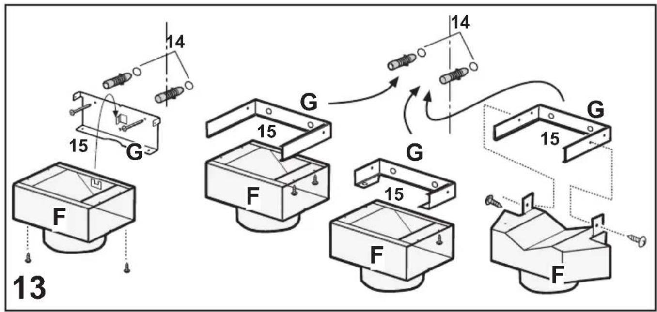
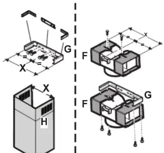
Assembling the deflector (only when a deflector composed of 3 parts is supplied – the deflector should be only for the filter version):
The three parts should be fixed with 2 screws, the deflector extension is adjustable and should correspond to the width of the chimney flue support, to which it is then fixed.
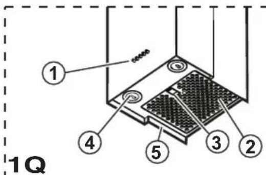
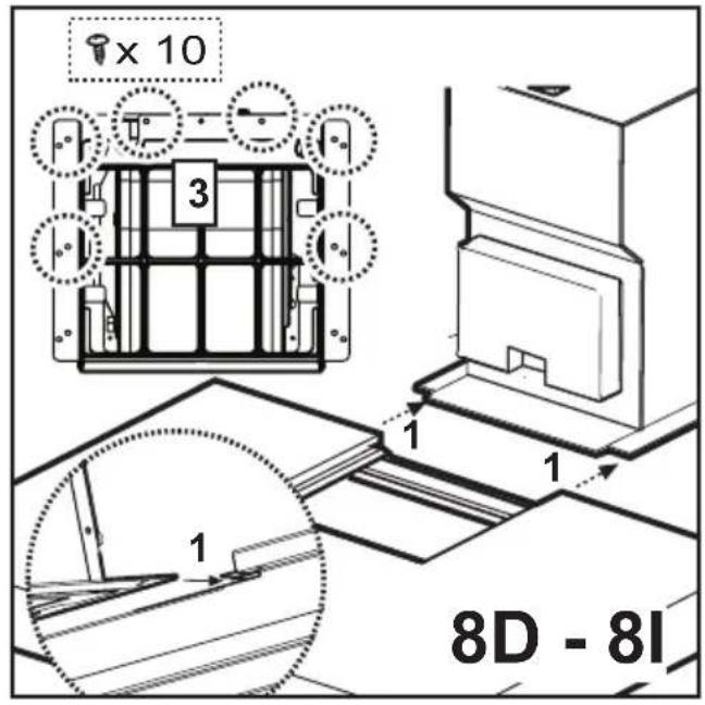
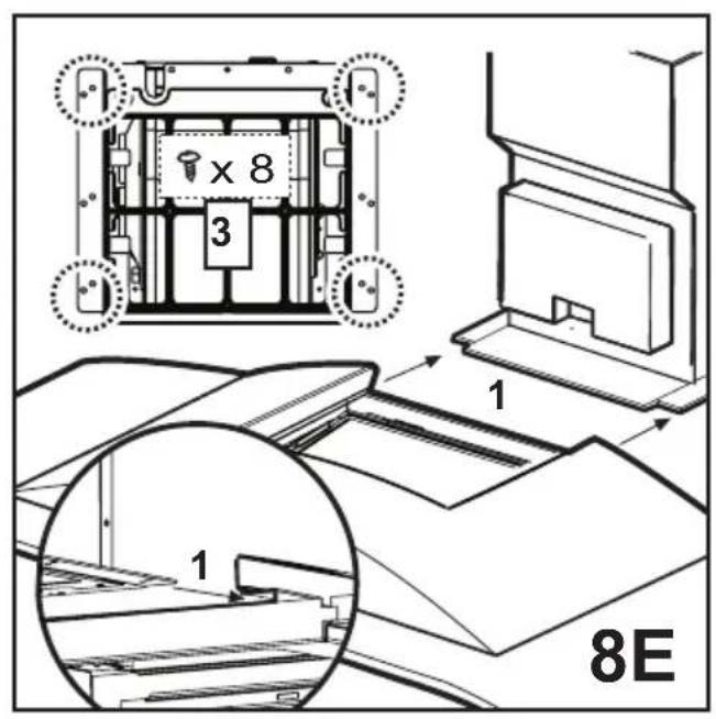
Only for the models illustrated in Fig. 1D/8D - 1E/8E - 1Q/8Q
Remove AND CONSERVE the screws that temporarily fix the flue units (for reasons of transport), the hood or the flue unit (on the basis of the model possessed) with the suction unit. The two parts should be disassembled to facilitate installation. Check how the parts are fixed together to repeat assemblage at the opportune moment.
Before fixing the hood to the suction unit check that the metal band (steam shield) that holds the lamp and the filter/s / greases is well attached to the front. If necessary adjust the position of the band forwards until the end stop.
Attention!
The chimney is predisposed for installation of the filter Version.
In certain models where it is required to use the cooker hood in the suction version then it is possible to overturn the upper section of the chimney
and insert it inside the lower section of the chimney so that the air-exit perforations are not visible. The chimneys in which this operation is possible are recognizable by their bracket fixing points G which are repeated also in the lower side of the upper section of the chimney (see installation sequence 20a-20b).
Attention! for all pre-assembled models:
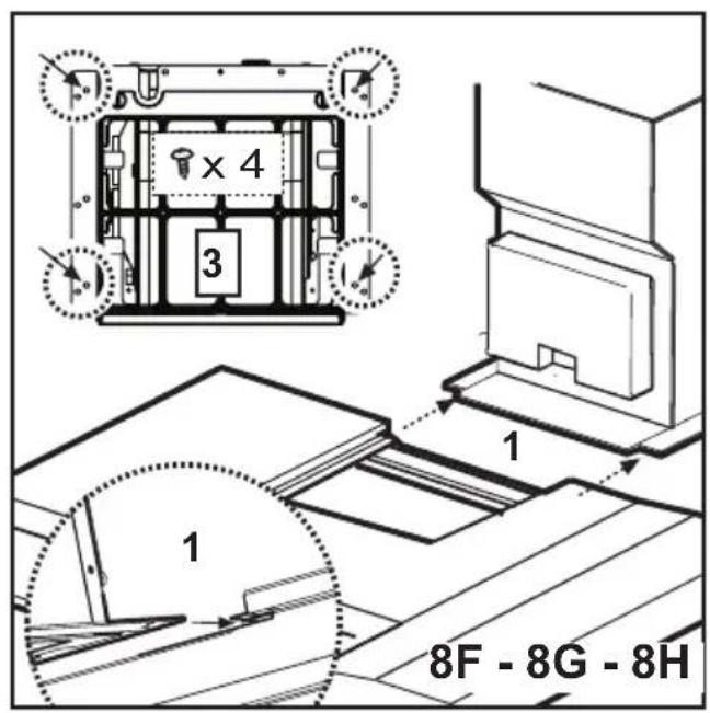
the mounting operations "1, 2, 3" should not be taken into consideration, for installation begin at operation "4".
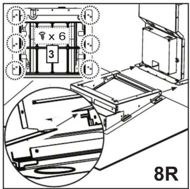
- Rest the suction unit on a flat surface and thread the lower
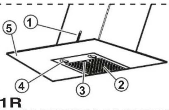
part of the hood onto it (consult the figure corresponding to the model in possession - Fig. 1C/8C - 1D/8D - 1I/8I - 1E/8E - 1F/8F - 1G/8G - 1H/8H - 1R/8R - 1N-1O-1P).
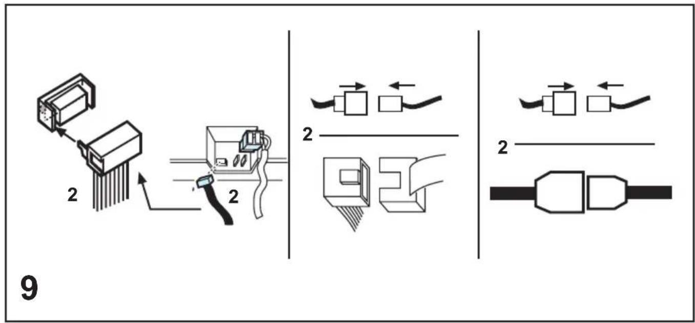
-
Make all the electrical connections between the two parts (Fig. 9).
-
Permanently fix the cooker hood to the suction group with the screws (consult the figure corresponding to the model in possession - Fig. 1C/8C - 1D/8D - 1I/8I - 1E/8E - 1F/8F - 1G/8G - 1H/8H - 1R/8R - 1N-1O-1P).
-
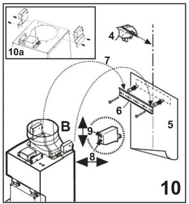
Using a pencil, draw a line on the wall, extending up to the ceiling, to mark the centre. This will facilitate installation (Fig. 10).
-
Rest the drilling template against the wall: the vertical centre line printed on the drilling template must correspond to the centre line drawn on the wall, and the bottom edge of the drilling template must correspond to the bottom edge of the hood: bear in mind that, when installation is complete, the underside of the hood must be at least 50 cm above the cooker top in the case of electric cookers, and at least 65 cm above the cooker top in the case of gas or mixed cookers.
-
Place the lower support bracket on the perforation diagram making it coincide with the traced triangle, mark the two external holes and perforate. Remove the perforation diagram, insert two wall-dowels and fix the support bracket of the hood with two 5x45 mm screws (Fig. 10).
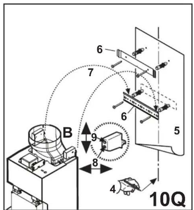
Attention: only the models illustrated in Fig. 1Q/10Q:
Fix the central bracket with two screws and wall-dowels above the lower bracket (see perforation diagram for positioning the holes).
- If supplied dismantled, fix the hooks to the side of the
aspiration group with two screws (fig. 10a). Hang the hood onto the lower bracket.
-
Adjust the distance of the hood from the wall.
-
Adjust the horizontal position of the hood.
-
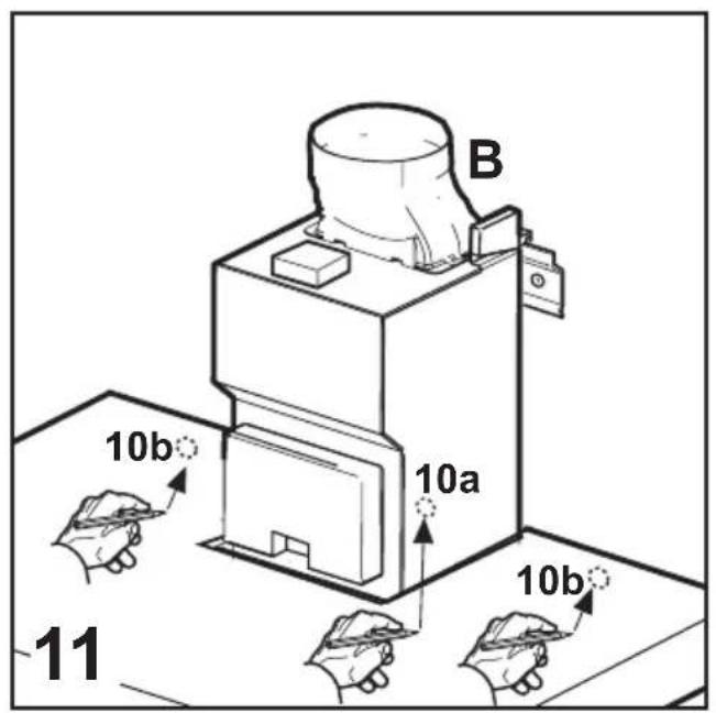
Using a pencil mark the cooker hood permanent drill hole inside the suction group (1 or 2 fixing points are necessary for permanent mounting) (Fig. 11).
-
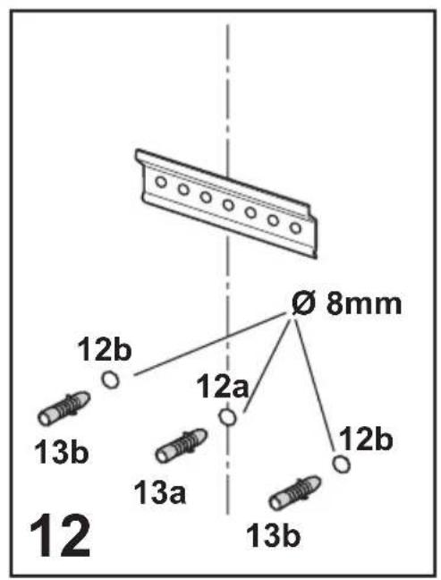
Remove the hood from the lower bracket.
-
Drill at the point marked (∅8mm) (Fig. 12).
-
Insert 1 or 2 wall screw anchors according to requirement.
-
Apply the flues support bracket „G“ to the wall adherent to the ceiling, use the flues support bracket as a perforation diagram (if present, the small slot on the support must coincide with the line drawn previously on the wall) and mark two holes with a pencil. Make the holes (∅8mm), and insert 2 dowels (Fig. 13).
-
Fix the chimney support bracket to the wall using two 5x45mm screws.
-
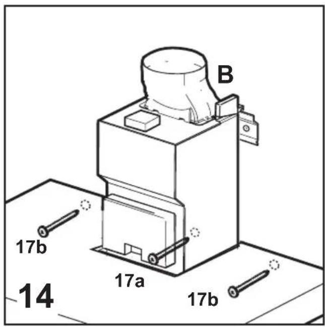
Hook the hood onto the bottom bracket.
-
Fix the hood into its final position on the wall (ABSOLUTELY ESSENTIAL) (Fig. 14).
-
Connect a pipe (pipe and pipe clamps not provided, to be purchased separately) for discharge of fumes to the connection ring located over the suction motor unit. If the hood is to be used in ducting version, the other end of the pipe must be connected to a device expelling the fumes to the outside. If the hood is to be used in filter version, then fix the deflector F to the chimney support bracket G and connect the other extremity of the pipe to the connection ring placed on the deflector F (Fig. 13-15).
-
Connect the electricity.
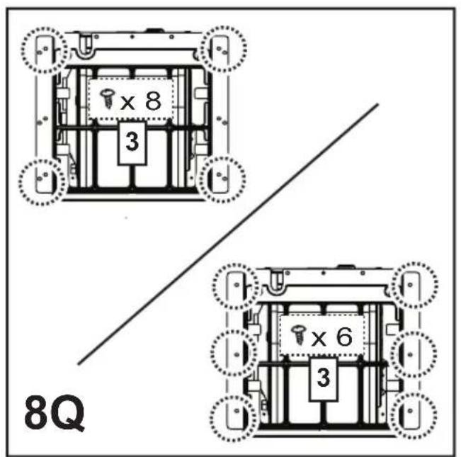
Attention: only the models illustrated in Fig. 1Q: Continue from the installation sequence number 23.
- Apply the chimney stacks and fasten them at the top to the chimney support „G“ (20b) using 2 screws (20a) (Fig. 16).
Only for model with optical fibers point lighting (Fig. 1G):
Check that the chimneys may be removed to permit access to the optical fibers lamp housing area.
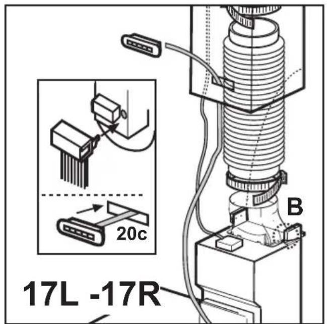
Only for the model with control panel on chimney flue (Fig. 1L- 17):
Insert the command plate from the motor group through the chimney flue slit from the inside towards the outside (20c).
Carry out the connection of the control panel to the command plate.
Attention! The terminal pivot on the plate MUST correspond to the drill hole on the connection block situated at the back of the control panel.
-
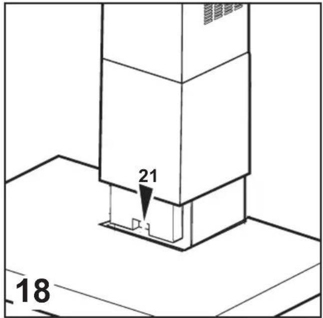
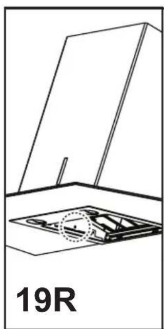
Slide the bottom section of the chimney down until it completely covers the suction unit and slots into the housing provided on top of the hood (Fig. 18).
-
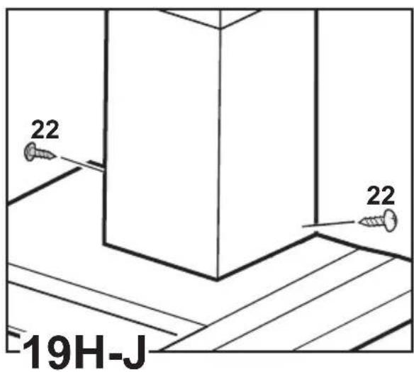
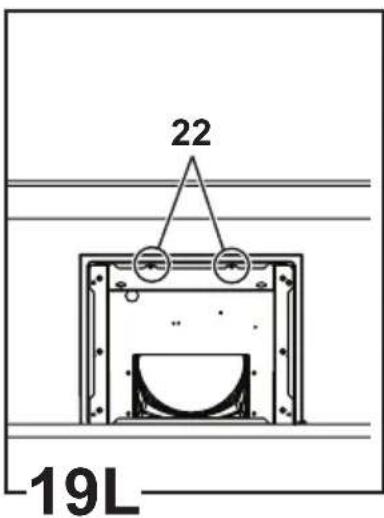
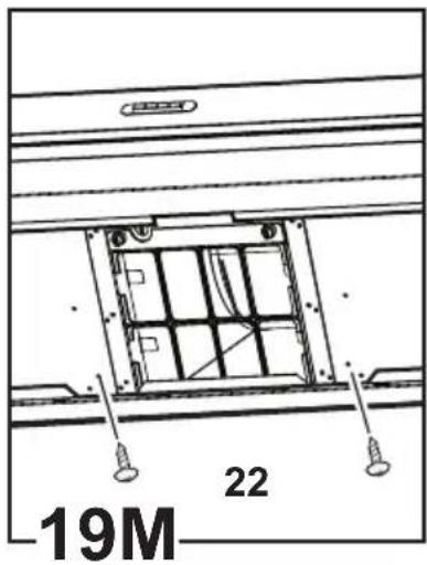
Fix the lower section of the chimney with two screws (only for the model in Fig. 1H/19H-1J/19J-1L/19L-1M/19M-1N/19N-1O/19O-1P/19P).
-
Only the models illustrated in Fig. 1Q:
- Put the flues unit on the suction unit. Connect the electricity between the two parts (Fig. 9). - Fix the flue units definitively to the suction unit with the screws (consult the figure corresponding to the model in possession) (Fig. 8Q).
Attention! Check that the lower section of the flue fits onto the central bracket (Fig. 20).
- Fix the upper section of the flue units to the flues support bracket with two screws (Fig. 16).
Remount the carbon filter frame and the fat/s filter/s and check the perfect functioning of the hood.
Electrical connection
The electrical tension must correspond to the tension noted on the label placed inside the cooker hood. Connect the electrical plug, where provided, to the an easily accessible outlet in conformity with local standards in force.
Where an electrical plug is not provided (for direct connection to electrical network) place a standards approved bipolar switch with an aperture distance of not less than 3mm (accessible) from the contacts.
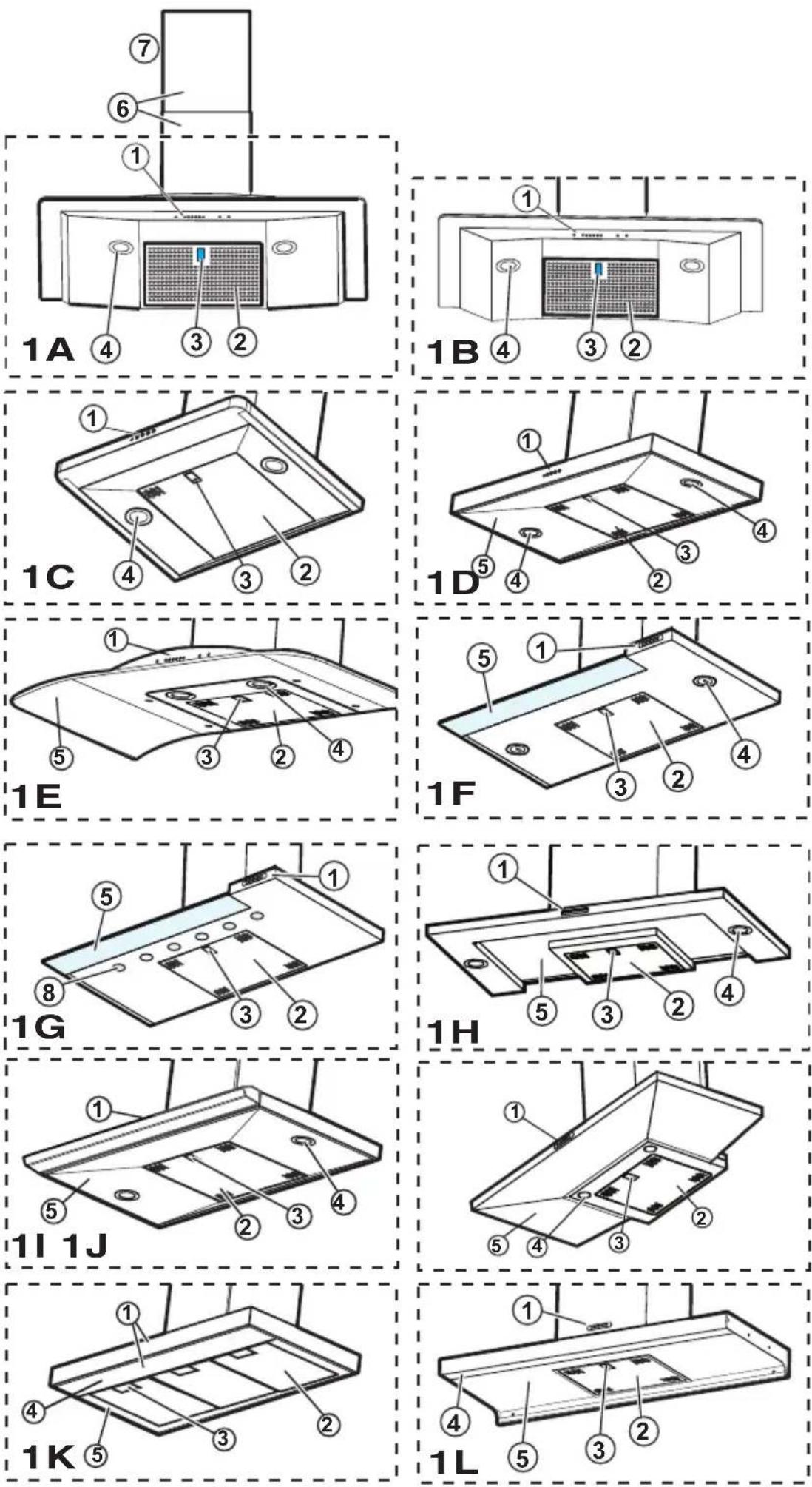
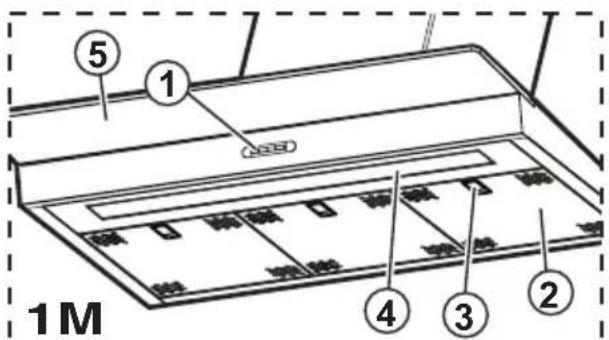
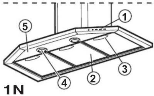
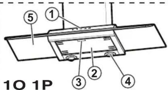
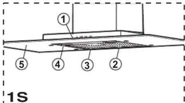
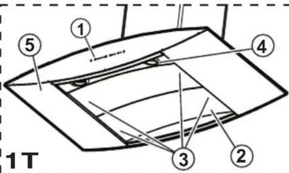
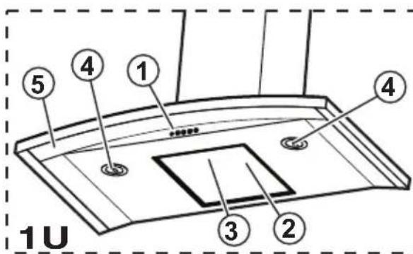
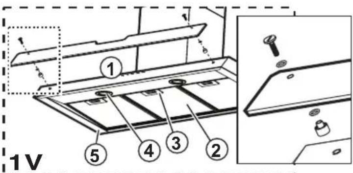
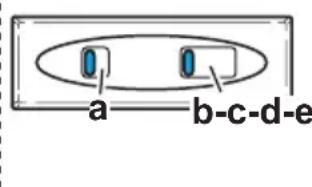
Description of the hood - Fig. 1
- Control panel
- Grease filter
- Grease filter release handle
- lamp
- Vapour screen
- Telescopic chimney
- Air outlet (used for filter version only)
- point lighting (only for the model in Fig. 1G)
Operation
Use the high suction speed in cases of concentrated kitchen vapours. It is recommended that the cooker hood suction is switched on for 5 minutes prior to cooking and to leave in operation during cooking and for another 15 minutes approximately after terminating cooking.
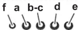
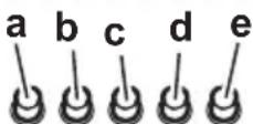
Functioning - Model with Keyboard
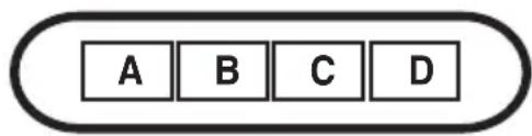
A. on/off light switch
B. on/off aspiration switch and minimum power selection
B+C. medium power selection aspiration switch
B+D. maximum power selection aspiration switch
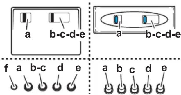
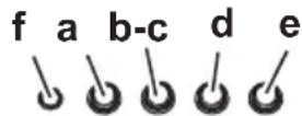
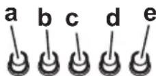
a. ON/OFF lighting
b. OFF motors
c. - d. - e. Minimum suction power (c.), medium (d.), maximum (e.).
f. Operation warning light (where present).
Note: Some models only possess one suction Power.
Attention: the models with an electric valve are supplied with 3 keys:
(a)Light ON/OFF, (b)Electric Valve Closure and (c)Opening.
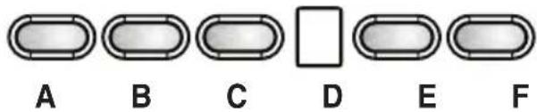
A - Lighting, on/off.
B - Fan off (Stand by)
C - Timer for selected speed (visualizes the speed selected and flashing LED on the lower side of the display).
This knob permits the operation of the cooker hood for a established period:
20 minutes if the speed selected is 1
15 minutes if the speed selected is 2
10 minutes if the speed selected is 3
5 minutes if the intensive speed P is selected.
D - Display showing:
• Fan speed (1-3-P).
- Change grease filters (grease filter saturation indicator - F)
After washing the anti-grease filter, depress knob B for about 3 seconds. The letter F will disappear from the display.
- Change activated carbon filters (carbon filter saturation indicator - C).
After replacing the charcoal filter, depress knob B for about 3 seconds. The letter C will disappear from the display.
- When the led in the lower right side is on, it indicates that the cooker hood is ready for operation ("standby" position), the flashing LED indicates that the timer has been activated for selected speed.
Warning!
The active carbon filter saturation function is not activated.
In order to activate the carbon filter saturation indicator, press buttons E and F simultaneously for 3 seconds. Initially, only letter F will be displayed, then after the 3 seconds have passed, letter C will be displayed as well, indicating that the carbon filter saturation control system is active.
To switch off the system, re-press the same two buttons: letter C appear on display and after 3 seconds letter it disappear and the device will be switched off.
E - Knob to decrease the speed: from intensive speed P to speed level 1.
F - Knob to increase (standby) speed to intensive speed P.
Attention! Intensive speed P has a duration of 5 minutes after which the cooker hood automatically sets the speed to level 2 (suction power).
If the hood fails to operate correctly, briefly disconnect it from the mains power supply for almost 5 sec. by pulling out the plug. Then plug it in again and try once more before contacting the Technical Assistance Service.
Warning!
Always press the fan off button A before disconnecting the hood from the mains supply.

A - OFF key (Display off) /Stand-by (led lit on the display) - press for a long time to select the function desired.
B - Lighting, on/off.
C - Timer for selected speed (visualizes the speed selected and flashing LED on the lower side of the display). This knob permits the operation of the cooker hood for a established period:
20 minutes if the speed selected is 1
15 minutes if the speed selected is 2
10 minutes if the speed selected is 3
5 minutes if the intensive speed P is selected.
D - Display showing:
- Fan speed (1-3-P).
- Change grease filters (grease filter saturation indicator - F)
After washing the anti-grease filter, depress knob A for about 3 seconds. The letter F will disappear from the display.
- Change activated carbon filters (carbon filter saturation indicator - C).
After replacing the charcoal filter, depress knob A for about 3 seconds. The letter C will disappear from the display.
- When the led in the lower right side is on, it indicates that the cooker hood is ready for operation ("standby" position), the flashing LED indicates that the timer has been activated for selected speed.
Attention! The active carbon filter saturation indicator is normally deactivated, to activate it:
Set the hood on OFF (display off), press keys C and G contemporaneously for 3 secs.
Initially, only letter F will fbe displayed, then after the 3 seconds have passed, letter C will be displayed as well, indicating that the carbon filter saturation control system is active.
To switch off the system, re-press the same two buttons: letter C appear on display and after 3 seconds letter it disappear and the device will be switched off.
E - Knob to decrease the speed.
F - Knob to increase the speed.
G - Timed intensive speed button: the hood operates at this speed for 5 minutes and than returns to the previous settings. The display will show P and a blinking dot. This function can be cancelled by pressing button A.
If the hood fails to operate correctly, briefly disconnect it from the mains power supply for almost 5 sec. by pulling out the plug. Then plug it in again and try once more before contacting the Technical Assistance Service.
Warning!
Always press the fan off button A before disconnecting the hood from the mains supply.
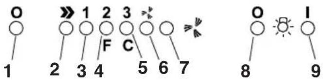
1- Motor OFF button
2- ON button and motor speed selection button 1 - 2 - 3 - 1 - 2 - . . .
3- Speed 1 LED
4- Speed 2 LED and metal grease filter saturation LED (in this latter case, the LED will flash - See instructions on grease filter cleaning).
Once the grease filters have been cleaned, press button 1 for about 3 seconds until you hear the acoustic signal (beep): the LED 4 will now stop flashing.
5- Speed 3 LED and active carbon filter saturation LED _ (in this latter case, the LED will flash - See instructions on active carbon filter replacement).
Once you have replaced the charcoal filter, press button 1 for about 3 seconds until you hear the acoustic signal (beep). LED 5 will now stop flashing.
Warning!
The active carbon filter saturation LED is not activated. In order to activate the active carbon filter saturation indicator, press buttons 2 and 7 simultaneously for 3 seconds. Initially, only LED 4 will flash, then after the 3 seconds have passed, LED 5 will also start flashing, indicating that the active carbon filter saturation control system is active.
To switch off the system, re-press the same two buttons: after 3 seconds LED 5 will stop flashing and the device will be switched off.
6 - Intensive speed LED
7 - Intensive speed ON switch
This speed should be used when the concentration of cooking fumes or odours is particularly strong (for example when frying, cooking fish etc.). T h e
fast speed will run for about 5 minutes and then return to the speed previously set automatically (1, 2 or 3), or switch off if no speed was selected.
To turn off the fast speed, before the end of the 5 minutes, press button 1 or button 2.
8 - OFF lamp button
9 - ON lamp button
If the hood fails to operate correctly, briefly disconnect it from the mains power supply for almost 5 sec. by pulling out the plug. Then plug it in again and try once more before contacting the Technical Assistance Service.
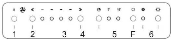
1- Motor OFF key.
2- Diminishes the speed.
3- Increases the speed.
4- 5/15 minutes timer. Inserts and extracts the timer. The speed in function is turned off automatically.
5- Resets carbon filters saturation indicator.
When the F led lights up, the carbon filter should be cleaned or changed.
Press for at least 3 seconds after having changed the carbon filter. The F led will turn off to indicate the resetting of the saturation indicator.
6- ON/OFF light.
If the hood fails to operate correctly, briefly disconnect it from the mains power supply for almost 5 sec. by pulling out the plug. Then plug it in again and try once more before contacting the Technical Assistance Service.
Electronic model with sensor
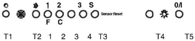
T1 - Hood On/Off key
T2 - Increase cyclical motor speed key.
Pressing the first time activates speed 1. A Led (1-2-3), corresponding to each speed, switches on. Led 4 flashes at intensive speed.
After 5 minutes intensive speed is reduced to the second speed. If key T2 is pressed before the end of the 5 minutes, the hood returns to the first speed.
T5 -Lights On/Off key.
Filter signals
(function active with the hood on): the fats filter signal appears after 80 hours functioning (Led 1 flashing).
The carbon filter signal appears after 320 hours (Led 2 flashing). In the case of simultaneous signalling of the fats and carbon filters, Leds 1 and 2 flash alternatively.
Reset filter signals:
press key T4 for 3 seconds until Led 1 switches off (fats filter). In the case of both filters (fats and carbon) signalling, repeat the operation just described: pressing T4 the first time switches off Leds 1 and 2 that are flashing alternatively. Immediately afterwards Led 2 flashes again: at this point press T4 again for 3 seconds. A beep signals each time the operation is completed.
Enabling the carbon filter signal:
the hood is enabled only for the fats filter signal. To enable the carbon filter signal: hood in Off, press keys T2 and T4 for 3 seconds. The flashing of Leds 1 and 2 signals the completion of the setting. To disenable the carbon filter signal, repeat this operation again (always with the hood in Off). A beep signals each time the operation is completed.
Automatic calibration:
the system carries calibration out automatically about every 30 minutes (calibration of the parameters functioning of the sensors).
Manual calibration:
with the hood in Off, press keys T3 and T4 until the beep.
Automatic functioning:
to activate automatic functioning, press key T3: Led 4 switches on. To return to manual functioning, press key T1, T2 or T3.
Sensors test:
this happens continuously during automatic functioning. In the case of damage all the Leds flash: in this case, return to manual functioning, pressing keys T1, T2 or T3.
Selecting cooking top:
this operation optimises the automatic functioning of the hood: with the hood in Off press keys T2 and T3 for about 3 seconds until the cooking top at present in use is seen:
gas top - Led 1 on
induction top - Led 2 on
electric top - Led 3 on.
Select the cooking top requested pressing T2, then press T2 and T3 simultaneously for three seconds until the Beep. Alt the
end the hood switches off.
The gas top is the default state.
Attention: carry out this operation the first time the hood is switched on.
Maintenance
Prior to any maintenance operation ensure that the cooker hood is disconnected from the power supply.
Cleaning: The cooker hood should be cleaned regularly internally and externally.
For cleaning use a cloth moistened with denatured alcohol or neutral liquid detergents. Avoid abrasive detergents.
Warning: Failure to carry out the basic standards of the cleaning of the cooker hood and replacement of the filters may cause fire risks.
Therefore we recommend observing these instructions.
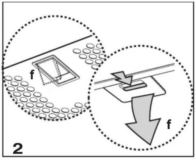
Grease filter
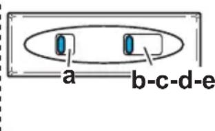
This must be cleaned once a month (or when the filter saturation indication system – if envisaged on the model in possession – indicates this necessity – see previous page) using non aggressive detergents, either by hand or in the dishwasher, which must be set to a low temperature and a short cycle. When washed in a dishwasher, the grease filter may discolour slightly, but this does not affect its filtering capacity. To remove the grease filter, pull the spring release handle (f) - (Fig. 2).
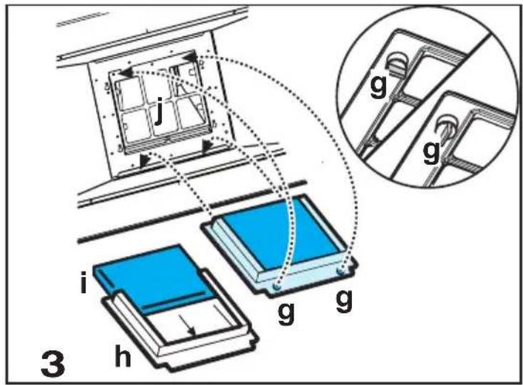
Charcoal filter (filter version only)
It absorbs unpleasant odours caused by cooking.
The charcoal filter can be washed once every two months (or when the filter saturation indication system – if envisaged on the model in possession – indicates this necessity – see previous page) using hot water and a suitable detergent, or in a dishwasher at 65^ C (if the dishwasher is used, select the full cycle function and leave dishes out).
Eliminate excess water without damaging the filter, then remove the mattress located inside the plastic frame and put it in the oven for 10 minutes at 100^ C to dry completely. Replace the mattress every 3 years and when the cloth is damaged.
Remove the filter holder frame by turning the knobs (g) 90° that affix the chimney to the cooker hood (Fig. 3). Insert the pad (i) of activated carbon into the frame (h) and fit the whole back into its housing (j).
It is possible to use a traditional carbon filter, neither washable nor regenerable, to be replaced every 3 - 4 months.
The filter holder frame of the carbon filter is welded together; the eventual frame supplied with the hood is not, therefore, to be used.
Insert it into its housing and fix it turning the 2 plastic knobs.
Replacing lamps
Warning!
Prior to touching the light bulbs ensure they are cooled down.
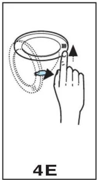
For models shown in Fig. 1E + Fig. 4E:
-
Press on the lamp cover and release to open.
-
Replace the damaged light bulb. Only use halogen bulbs of 20W max (G4), making sure you do not touch them with your hands.
-
Close the lamp cover (it will snap shut).
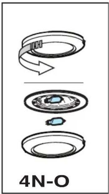
For models shown in Fig. 1N/O + Fig. 4N/O:
-
Unscrew the lamp cover.
-
Replace the damaged light bulb. Only use halogen bulbs of 20W max (G4), making sure you do not touch them with your hands.
-
Refit the lamp cover.
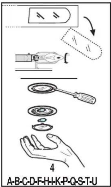
For models shown in Fig.1+Fig.4 (A/B/C/D/F/H/I/K/P/Q/S/T/U/V):
-
Extract the lamp cover by levering it off with a small screwdriver or similar tool.
-
Replace the damaged light bulb. Only use halogen bulbs of 20W max (G4), making sure you do not touch them with your hands.
-
Close the lamp cover (it will snap shut).
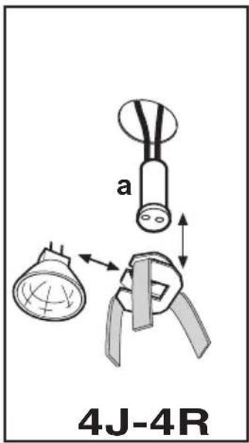
For models shown in Fig. 1J + Fig. 4J:
-
Use a small screwdriver as a lever on the borders of the lamp in order to remove the lightbulb.
-
Unthread the connector „a“.
-
Slide out the lightbulb to be replaced and replace with a new 12V 20W 30° ∅35 12V GU4 PHILIPS STANDARD LINE code 425409.
-
Carry out the replacement and mount the new lightbulb by following instructions in the reverse.
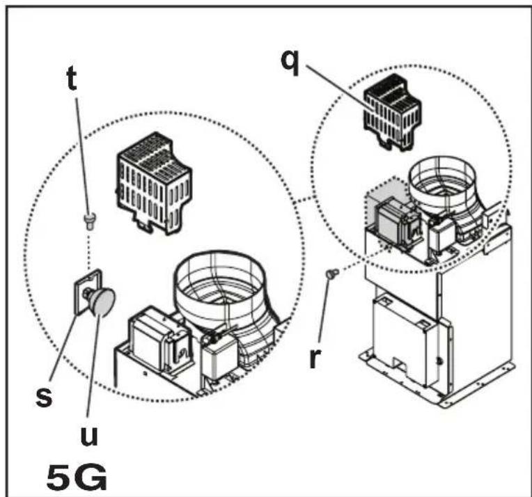
For models shown in Fig. 1G + Fig. 5G:
Dismount the chimneys: remove the two screws (20 a) that attaches the upper chimney to the support „G“ (Fig. 16).
Remove the box „q“: remove the screw „r“ that secures the cooker hood.
Remove the lamp housing „s“: remove the screws „t“ that position the housing in the lamp housing area.
Extract the damaged lamp.
Use only PHILIPS type 14515 (GX 5.3) 12V - 75W halogen bulbs..
Reposition and secure the lamp housing „s“ and the box „q“ and remount the chimneys.
For models shown in Fig. 1K + Fig. 4K:
Certain versions of this cooker hood provide for an incandescent lamp at 40W maximum (E14), remove the lamp cover to access the lamp housing and carry out any replacements.
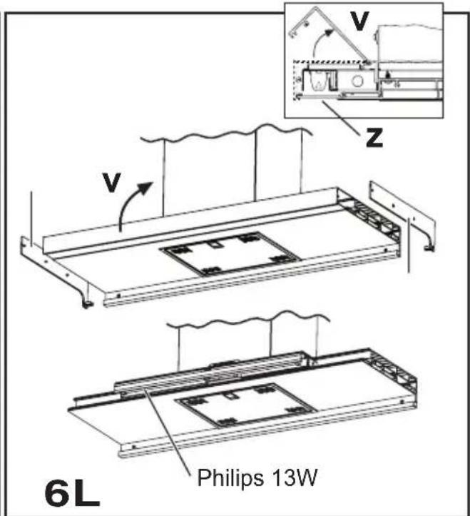
Only for the illustrated model in Fig. 1L + Fig. 6L:
-
Open the front panel "v" upwards, which holds the lamp in place, ensuring to hold the lamp "z" with one hand.
-
Replace the damaged lamp with one of identical technical characteristics.
Attention! To guarantee the equivalent quality of lighting, it is recommended to use the same type of lamp bulb:
Philips neon Lamp bulb 13W Code Ref. 8711500644305. Ensure that the transparent part of the lamp bulb is facing inwards so as to guarantee correct light distribution.
- Replacing the starter:
Use a starter with identical technical characteristics. Recommended starter: Use a Philips S10 starter.
- Remount the lamp housing and the front panel in the inverse in relation to the dismounting.
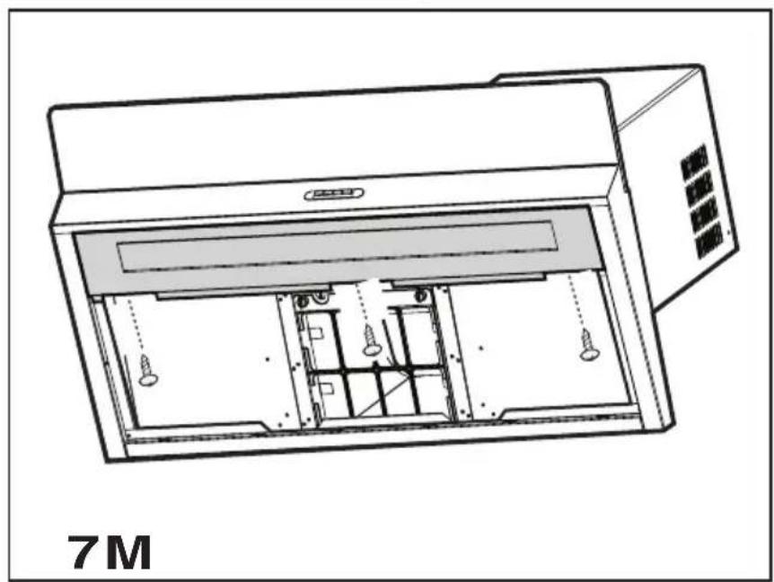
Only for the models illustrated in Fig. 1M + Fig. 7M:
-
Remove the grease filters.
-
Remove the ceiling light unscrewing the 3 screws that fix it to the hood (hold the ceiling light to prevent it falling).
-
Change the damaged bulb with one with identical technical characteristics.
Changing the starter
Use a starter with identical technical characteristics.
Starter advised: use a Phillips S10 starter.
- Remount the ceiling light and the grease filters in the reverse manner to the montage.
If the lights do not work, make sure that the lamps are fitted properly into their housings before you call for technical assistance.
Caution
This appliance is designed to be operated by adults. Children should not be allowed to tamper with the controls or play with the appliance.
Do not use the cooker hood where the grill is not correctly fixed! The suctioned air must not be conveyed in the same channel used for fumes discharged by appliances powered by other than electricity. The environment must always be adequately aerated when the cooker hood and other appliances powered by other than electricity are used at the same time. Flambé cooking with a cooker hood is prohibited. The use of a free flame is damaging to the filters and may cause fire accidents, therefore free flame cooking must be avoided. Frying of foods must be kept under close control in order to avoid overheated oil catching fire. Carry out fumes discharging in accordance with the regulations in force by local laws for safety and technical restrictions.
This appliance is marked according to the European directive 2002/96/EC on Waste Electrical and Electronic Equipment (WEEE). By ensuring this product is disposed of correctly, you will help prevent potential negative consequences for the environment and human health, which could otherwise be caused by inappropriate waste handling of this product.
The symbol on the product, or on the documents accompanying the product, indicates that this appliance may not be treated as household waste. Instead it shall be handed over to the applicable collection point for the recycling of electrical and electronic equipment. Disposal must be carried out in accordance with local environmental regulations for waste disposal.
For more detailed information about treatment, recovery and recycling of this product, please contact your local city office, your household waste disposal service or the shop where you purchased the product.
Assembler le support cheminée (3 parties):
A - Touche illumination, on/off
B - Touche off aspiration (position d'attente/stand-by)
B - Touche illumination, on/off
T1 - Touche On/Off hotte
a. ON/OFF lichten
b. OFF motoren
T1 - Afzuigkap On/Off knop
Solo per i modelli illustrati in Fig. 1E/8E - 1D/8D - 1Q/8Q
a. ON/OFF luces.
b. OFF motores.
Pouze pro modely ilustrované na obr. 1D/8D - 1E/8E - 1Q/8Q


- Installation
- Attention!
- Electrical connection
- Description of the hood - Fig. 1
- Operation
- Functioning - Model with Keyboard
- Warning!
- Electronic model with sensor
- T1 - Hood On/Off key
- T2 - Increase cyclical motor speed key.
- T5 -Lights On/Off key.
- Filter signals
- Reset filter signals:
- Enabling the carbon filter signal:
- Automatic calibration:
- Manual calibration:
- Automatic functioning:
- Sensors test:
- Selecting cooking top:
- Maintenance
- Grease filter
- Charcoal filter (filter version only)
- Replacing lamps
- For models shown in Fig. 1E + Fig. 4E:
- For models shown in Fig. 1N/O + Fig. 4N/O:
- For models shown in Fig.1+Fig.4 (A/B/C/D/F/H/I/K/P/Q/S/T/U/V):
- For models shown in Fig. 1J + Fig. 4J:
- For models shown in Fig. 1G + Fig. 5G:
- For models shown in Fig. 1K + Fig. 4K:
- Only for the illustrated model in Fig. 1L + Fig. 6L:
- Only for the models illustrated in Fig. 1M + Fig. 7M:
- Caution
- T1 - Touche On/Off hotte
- T1 - Afzuigkap On/Off knop
- Pouze pro modely ilustrované na obr. 1D/8D - 1E/8E - 1Q/8Q
Brand : FAGOR
Model : 3CFT9 BRS X
Category : Basket