VM118 - Remote control VELLEMAN - Free user manual and instructions
Find the device manual for free VM118 VELLEMAN in PDF.
| Product type | Remote control for 8-channel RF receiver |
| Brand | Velleman |
| Model | VM118 |
| Dimensions (transmitter) | 150 x 58 x 23 mm |
| Power supply (transmitter) | 3 AAA batteries (1.5 V) not included |
| Power supply (receiver) | 12 VAC / 500 mA |
| Operating frequency | 433 MHz |
| Maximum range | 50 m (in open field, without obstacles) |
| Number of channels | 8 |
| Number of addresses | 8 (adjustable) |
| Relay output functions | Momentary contact or toggle (on/off) configurable |
| Special function | Shift key to deactivate all relays (All clear) |
| LED indicators | Power, channel, data in, configuration mode |
| Receiver mounting type | DIN rail (suitable housing available as option, ref. B8006) |
| Relay contacts | 8 contacts, 5 A / 230 VAC max, with VDR protection |
| Safety instructions | Avoid moisture, shocks, do not exceed limit values |
| Maintenance | Clean with a dry cloth, replace worn batteries |
| Warranty | 2 years (with proof of purchase) |
| Certification | FCC approved, ID code: NLO8058 |
| Declaration of conformity | Available at www.velleman.be |
| Disposable batteries | Follow local laws for recycling |
| Configuration | Via transmitter, hold shift key + number |
| Exit configuration mode | Shift key or after 15 s of inactivity |
Frequently Asked Questions - VM118 VELLEMAN
User questions about VM118 VELLEMAN
0 question about this device. Answer the ones you know or ask your own.
Ask a new question about this device
Download the instructions for your Remote control in PDF format for free! Find your manual VM118 - VELLEMAN and take your electronic device back in hand. On this page are published all the documents necessary for the use of your device. VM118 by VELLEMAN.
USER MANUAL VM118 VELLEMAN
EIGHT CHANNEL RF REMOTE CONTROL SET
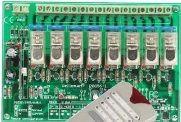
natural_image
Green printed circuit board with multiple electronic components and a close-up of a red LED (no readable text or symbols)VM118
8-channel RF remote control set 3
8-Kanaals RF afstandsbedieningset 11
This device complies with Part 15 of the FCC Rules. Operation is subject to the following two conditions: (1) this device may not cause harmful interference, and (2) this device must accept any interference received, including interference that may cause undesired operation.
If this equipment does cause harmful interference to radio or television reception, which can be determined by turning the equipment off and on, the user is encouraged to try to correct the interference by one or more of the following measures:
- Reorient or relocate the receiving antenna.
- Increase the separation between the equipment and receiver.
- Consult the dealer or an experienced radio/TV technician for help.
If the user modifies this unit, and these modifications are not approved by Velleman, the FCC may withdraw the user's right to operate the equipment.
Details on the FCC regulation can aslo be found on the internet at http://www.fcc.gov
For questions regarding your product, contact:
Velleman Inc, 7354 Tower Street, Fort Worth, TX 76118
Or head office Velleman:
Legen Heirweg 33, 9890 Gavere
Belgium
FCC approved ID code : NLO8058
Thank you for purchasing this module. Please read the instructions carefully to ensure correct and safe use of this device.

READ THE OPERATING AND MAINTENANCE INSTRUCTIONS IN THIS USER'S GUIDE CAREFULLY.
WARRANTY
This product is guaranteed against defects in components and construction from the moment it is purchased and for a period of TWO YEAR starting from the date of sale. This guarantee is only valid if the unit is submitted together with the original purchase invoice. VELLEMAN components Ltd limits its responsibility to the reparation of defects or, as VELLEMAN components Ltd deems necessary, to the replacement or reparation of defective components. Costs and risks connected to the transport, removal or placement of the product, or any other costs directly or indirectly connected to the repair, will not be reimbursed by VELLEMAN components Ltd. VELLEMAN components Ltd will not be held responsible for any damages caused by the malfunctioning of a unit.
CONTENTS :
RECEIVER : 4
FEATURES & SPECIFICATIONS 4
POWER SUPPLY 5
OUTPUT CONNECTION EXAMPLE 6
TRANSMITTER : 7
FEATURES & SPECIFICATIONS 7
USE 8
SETUP 9
SAFETY AND WARNING INSTRUCTIONS....10
SPECIFICATIONS & FEATURES
text_image
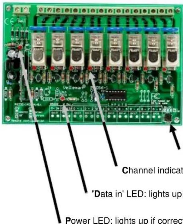
Channel indicate 'Data in' LED: lights up Power LED: lights up if correctRECEIVER :
FEATURES
☑ eight high quality relay contacts, 5A/230VAC max.
☑ relay outputs are transient suppressed using VDR's.
☑ LED confirmation on each relay contact.
SPECIFICATIONS
• power: 12Vac / 500mA
Test button, each press will activate the next relay
Channel indication LED's: lights up if the corresponding relay is activated
'Data in' LED: lights up if a transmitter signal is received
Power LED: lights up if correct power is supplied to the card
POWER SUPPLY
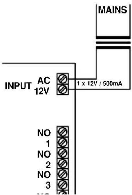
text_image
INPUT AC 12V 1 x 12V / 500mA NO 1 NO 2 NO 3 MAINSChoose a suitable location for the unit. Probably, the best location is near the fuse box. An optional enclosure (B8006) is available, for safe installation of the unit on a DIN rail.
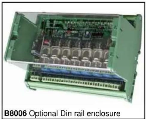
text_image
B8006 Optional Din rail enclosureThe drawings on the next pages shows connection examples with different input possibilities.

Make sure your wiring complies with the local safety requirements. If doubt, consult a licensed technician!
OUTPUT CONNECTION EXAMPLE
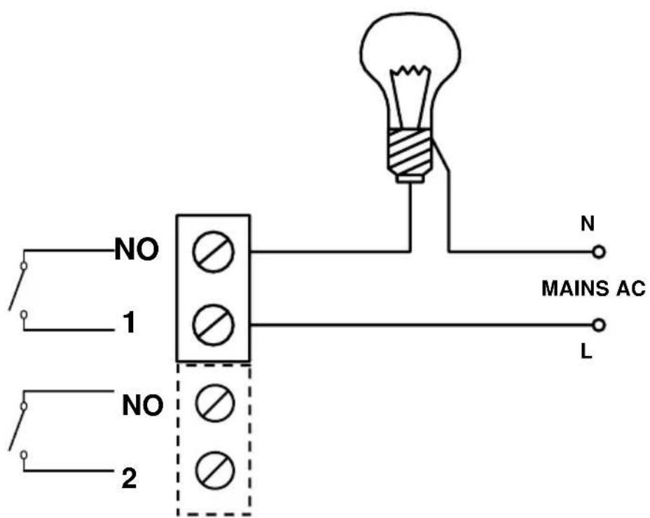
text_image
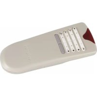
NO 1 NO 2 N MAINS AC LTRANSMITTER :
FEATURES
☑ 8 addresses allow the use of multiple receivers
'all clear'- function
☑ Toggle or momentary mode for each key
☑ Open-field range up to 50m
Rubber keypad
SPECIFICATIONS
• 8 digital encoded channels
• 433MHz operation
• LED function/mode indication
• Power supply: 3 AAA batteries (not included)
• Dimensions: 150x58x23mm
• FCC approved ID code: NLO8058
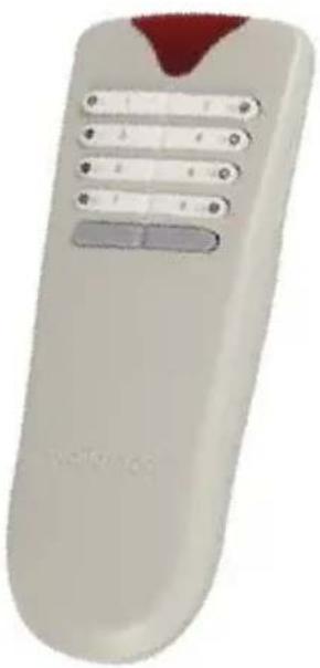
natural_image
White remote control with five buttons and a red triangular tip (no text or symbols visible)Velleman hereby certifies that the device VM118 meets the essential requirements and all other relevant stipulations of directive 1999/5/EG and 1995/5/EC.
For the complete conformity declaration check out :http://www.velleman.be/downloads/doC/declaration_VM118.pdf
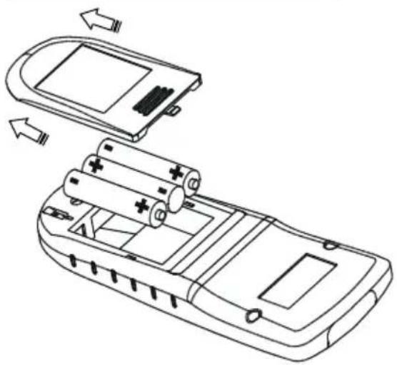
USE
Insert the batteries in the battery compartment as indicated in figure and close the compartment.
Remark : Respect your national and local laws when disposing of empty batteries.
natural_image
Line drawing of a mobile phone casing with battery pack and charging module (no text or symbols)CHANNEL SELECTION
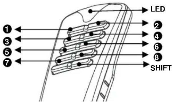
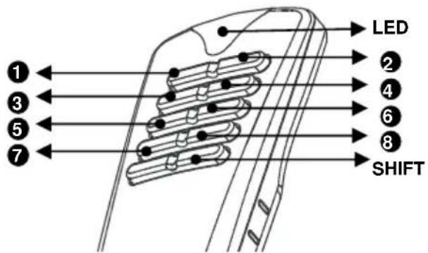
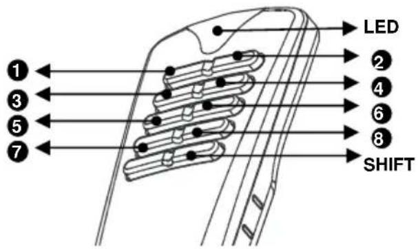
text_image
LED SHIFT- Channels 1..8 can be configured as 'toggle' (on/off) or pulse (see set-up)
- The indicator LED will briefly light when a button is pressed.
- Briefly pressing the shift button turns off all relays.
Note: All settings remain in memory after battery replacement
SET-UP
(1) Relay action output set-up
Each relay can be individually configured to behave as a toggle (ON/OFF) or as a pulse contact.
Hold 'shift' until the LED on the remote lights to enter the 'set-up'-mode then press '1' to enter output setup mode :
√ Press a button (1..8) to change the function of the corresponding output:
• LED flashes once: pulse mode,
• LED flashes twice: toggle mode.
Next, press 'shift' several times until the LED turns off to leave setup mode (*).
(2) Card address selection set-up (see also page 10)
In order to operate multiple units in close proximity without interference, each unit must have a unique address. 8 addresses are available, default address is 1.
| Addr | LD5 ... LD8 |
| 1 | ●●●○ |
| 2 | ●●○● |
| 3 | ○○●● |
| 4 | ●○●● |
| 5 | ●○●○ |
| 6 | ●○○● |
| 7 | ●○○○ |
| 8 | ○●●● |
First make sure the card is powered see page 5!
How to check the current address:
Hold 'shift' until the LED lights to enter the 'set-up'-mode.
➢ Press '2' to display the current address, the relay LED's LD5..LD8 indicate current address (see table).
Next, press 'shift' several times until the LED turns off to leave setup mode (*).
How to change the address:
Hold 'shift' until the LED lights to enter the 'set-up'-mode.
➢ Press '3' to allow address change, pressing a button (1..8) will change the address of the remote and the relay card (see table).
➢ Next, press 'shift' several times until the LED turns off to leave setup mode (*).
If more than one transmitter is used, please repeat point 2 using the other transmitter
Attention: All active cards will respond to this command. Remove power from cards which do not need to change their address.
(*) NOTE: If no button is pushed for about 15s, the unit will leave 'setup'-mode automatically.
HINT: Return to default card address 1
If an unknown card is used, or the transmitter is not longer at the same address as the card, it is possible to force the card to address 1.
First make sure the card is powered see page 5!
How to force to address "1":
Hold 'shift' until the LED lights to enter the 'set-up'-mode.
➢ Press '4' to force the current address to 1, LED LD8 on the card must light.
➢ Next, press 'shift' several times until the LED turns off to leave setup mode.
text_image
WARNINGS
All repairs should be executed by qualified technicians.

Avoid the installation of the module in locations with standing or running water or excessive humidity. Indoor use only!
SAFETY INSTRUCTIONS
■ Handle the module gently and carefully. Dropping it can damage the circuit board.
■ Never exceed the protection limit values indicated in the specifications.
As safety requirement vary, please check with your local authorities.
Facilitate the operation of the device by familiarising yourself with its adjustments and indications.
- Velleman modules are not suitable for use or as part of life support systems, or systems that might create hazardous situations of kind.
Repair under warranty is only possible with date and proof of purchase.
velleman
natural_image
3D rendering of a remote control device with buttons and a red tip (no text or symbols visible)natural_image
Line drawing of a mobile phone casing with battery pack and charging module (no text or symbols)KANAALKEUZE
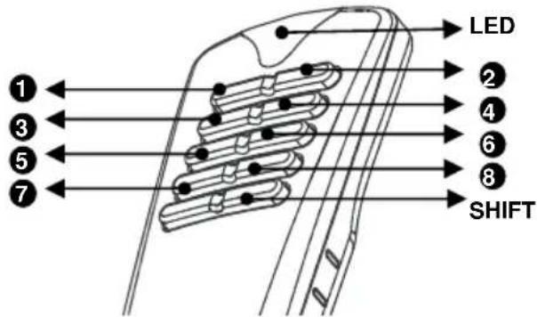
text_image
LED SHIFTtext_image
WAARSCHUWING
text_image
B8006 Optional Din rail enclosurenatural_image
White remote control device with buttons and a red triangular tip (no visible text or symbols)SPECIFICATIONS
natural_image
Diagram of a mobile phone casing showing battery pack, battery cell, and internal components (no text or labels)SELECTION DU CANAL
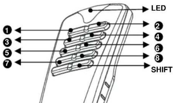
text_image
LED SHIFTtext_image
B8006 Optional Din rail enclosurenatural_image
White remote control with a red triangular tip and multiple buttons (no text or symbols visible)natural_image
Line drawing of a mobile phone casing with battery pack and charging mechanism (no text or symbols)KANALAUSWAHL
text_image
LED SHIFTtext_image
B8006 Optional Din rail enclosurenatural_image
White remote control with five buttons and a red triangular tip (no text or symbols visible)natural_image
Line drawing of a mobile phone casing with battery pack and external casing (no text or symbols)SELECCIÓN DEL CANAL
text_image
LED SHIFTR & TTE Declaration of Conformity
We, Velleman Components
Legen Heirweg 33
9890 Gavere - Belgium
declare, on our own responsibility, that the finished product:
trade name : 8-channel RF remote control
type or model : Nr. VM118
constituting the subject of this declaration, conforms with the essential requirements and other relevant stipulations of the R&TTE Directive (1999/5/EC).
The product conforms to the following norm(s) and/or one or several other normative
documents:
EMC (art. 3.1.b) : ETS 300 683 / 1995 (EN55022)
(on the basis of EMC DeC : Ⅲ)
SPECTRUM (art. 3.2): 1-ETS 300-220
Additional information:
For the US, FCC is also granted, code: NLO8058
Technical data are available and can be obtained from : VELLEMAN COMPONENTS
LEGEN HEIRWEG 33
9890 GAVERE - BELGIUM
Place and date of issue : 09/05/2005
Signed by or in name of the manufacturer :

Name: SANTENS STEPHAN
Capacity: R&D MANAGER
VM118
USER MANUAL
EIGHT CHANNEL RF REMOTE CONTROL SET

text_image
8 CHANNEL REMOTE CONTROL • Use a device to ensure the remote control • Use a device to ensure the remote control • Use a device to ensure the remote control • Use a device to ensure the remote control • Use a device to ensure the remote control • Use a device to ensure the remote control • Use a device to ensure the remote control • Use a device to ensure the remote control • Use a device to ensure the remote control • Use a device to ensure the remote control • Use a device to ensure the remote Control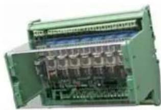
natural_image
Interior view of an open industrial control unit with visible circuit board and wiring (no text or labels)Belgium [Head office] Velleman Components +32(0)9 384 36 11
France Velleman Electronique +33(0)3 20 15 86 15
Netherlands Velleman Components +31(0)76 514 7563
USA Velleman Inc.
Spain Velleman Components +32(0)9 384 36 11
+1(817)284-7785

Modifications and typographical errors reserved - © Velleman Components nv - HVM118G - 2005 - ED1 (rev 2.0)