
K8023 - Remote control VELLEMAN - Free user manual and instructions
Find the device manual for free K8023 VELLEMAN in PDF.


| Product Type | Remote Control Kit |
| Brand | Velleman |
| Model | K8023 |
| Transmission Type | Radio Frequency (RF) 433 MHz |
| Range | Up to 100 meters (open area) |
| Number of Channels | 4 |
| Power Supply | 12V battery (type 23A) |
| Dimensions | 85 x 38 x 15 mm |
| Weight | 30 g (without battery) |
| Material | ABS plastic |
| Color | Black |
| Assembly | DIY kit (requires soldering) |
| Functions | On/Off, dimming, scene control |
| Compatibility | Velleman receivers (e.g., K8024) |
| Operating Temperature | -10°C to 50°C |
| Battery Life | Approximately 12 months (normal use) |
| Safety | Low voltage, CE certified |
| Included Components | PCB, components, casing, instructions |
| Repairability | Easy to repair with standard tools |
Frequently Asked Questions - K8023 VELLEMAN
User questions about K8023 VELLEMAN
0 question about this device. Answer the ones you know or ask your own.
Ask a new question about this device
Download the instructions for your Remote control in PDF format for free! Find your manual K8023 - VELLEMAN and take your electronic device back in hand. On this page are published all the documents necessary for the use of your device. K8023 by VELLEMAN.
USER MANUAL K8023 VELLEMAN
10 Channel, 2-Wire REMOTE CONTROL

natural_image
Two green circuit boards with electronic components and wiring, no visible text or symbolsK8023
Control up to 10 devices from a distance using only 2 wires.
Features:
☑ Microprocessor controlled.
☑ Inputs can be push-buttons, switches or open collector outputs from another device.
☑ The receiver section provide 10 open collector outputs which allow you to control relays directly.
☑ Terminal block connectors for all input and output connections are included.
☑ All outputs are provided with LED indication.
☑ Can be used with our kits: K8000,K8006,K8046,K8050,...
☑ Can be connected to our standard relay card: K6714, K6714-16
Specifications:
• 10 open collector outputs 50V/100mA
- Tested to a distance of up to 50m (55 yards) between control- and receiver section.
• Operating voltage: Single 12-15V AC or DC, 300mA.
- Dimensions control pcb (wxdxh): 70x50x16mm (2,7"x2"x0,6").
- Dimensions receiver pcb (wxdxh): 103x50x24mm(4"x2"x1").
1. Assembly (Skipping this can lead to troubles!)
Ok, so we have your attention. These hints will help you to make this project successful. Read them carefully.
1.1 Make sure you have the right tools:
• A good quality soldering iron (25-40W) with a small tip.
- Wipe it often on a wet sponge or cloth, to keep it clean; then apply solder to the tip, to give it a wet look. This is called 'thinning' and will protect the tip, and enables you to make good connections. When solder rolls off the tip, it needs cleaning.
- Thin raisin-core solder. Do not use any flux or grease.
- A diagonal cutter to trim excess wires. To avoid injury when cutting excess leads, hold the lead so they cannot fly towards the eyes.
- Needle nose pliers, for bending leads, or to hold components in place.
• Small blade and Phillips screwdrivers. A basic range is fine.

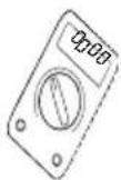
For some projects, a basic multi-meter is required, or might be handy
1.2 Assembly Hints :
⇒ Make sure the skill level matches your experience, to avoid disappointments.
⇒ Follow the instructions carefully. Read and understand the entire step before you perform each operation.
⇒ Perform the assembly in the correct order as stated in this manual
⇒ Position all parts on the PCB (Printed Circuit Board) as shown on the drawings.
⇒ Values on the circuit diagram are subject to changes.
Values in this assembly guide are correct*
⇒ Use the check-boxes to mark your progress.
⇒ Please read the included information on safety and customer service
* Typographical inaccuracies excluded. Always look for possible last minute manual updates, indicated as 'NOTE' on a separate leaflet.
1.3 Soldering Hints :
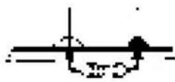
1- Mount the component against the PCB surface and carefully solder the leads
2- Make sure the solder joints are cone-shaped and shiny
3- Trim excess leads as close as possible to the solder joint


REMOVE THEM FROM THE TAPE ONE AT A TIME!
AXIAL COMPONENTS ARE TAPED IN THE CORRECT MOUNTING SEQUENCE!

Assembly of the receiver PCB : P8023R
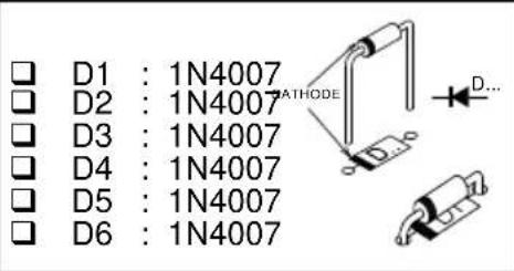
- Diodes. Watch the polarity!
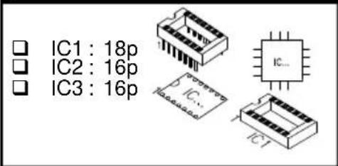
- IC sockets, Watch the position of the notch!
- Capacitors

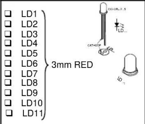
- LEDs. Watch the polarity!
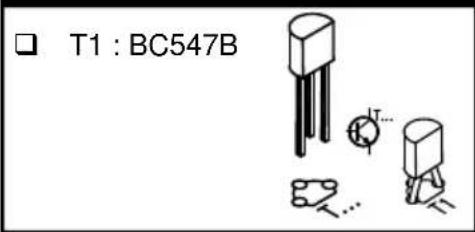
- Transistor
- Electrolytic capacitors.
Watch the polarity!

- Electrolytic capacitor.
Watch the polarity!

- Voltage regulator

- IC's mounting

Assembly of the receiver PCB : P8023S
- Diode. Watch the polarity!

- Resistors

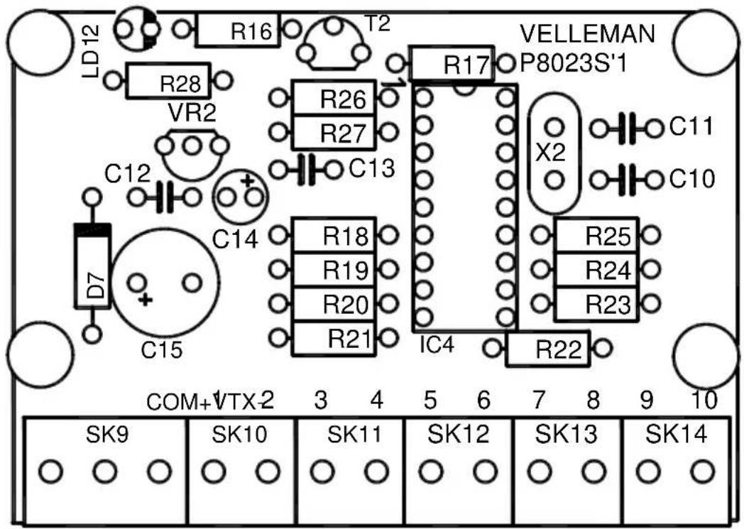
☐ R25 : 10K (1 - 0 - 3 - B) ☐ R26 : 10K (1 - 0 - 3 - B) ☐ R27 : 10K (1 - 0 - 3 - B) ☐ R28 : 220 (2 - 2 - 1 - B - 9)
3. IC socket, Watch the position of the notch!

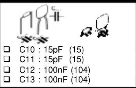
- Capacitors
- LED. Watch the polarity!

- Transistor

- Voltage regulator
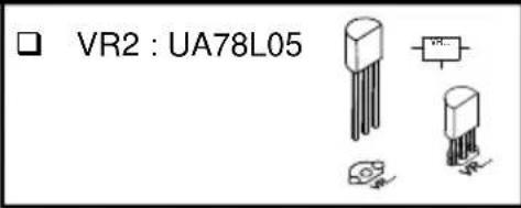
8. Electrolytic capacitor. Watch the polarity!

9. Quartz crystal
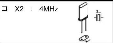
10. Screw connectors

11. Electrolytic capacitor. Watch the polarity!

12. IC mounting

13. Hook - up & Testing
Connect both PCB's P8023S and P8023R according to fig.1. Both push buttons and switches can be used to control the inputs. Keep the distance between the switches or push buttons and the circuit as short as possible. If the circuit is used in a noisy environment (e.g. proximity of electric motors, transformers, ....) or if the distance between the switches and the circuit exceeds 1m (3"), a shielded cable must be used to connect the switches. The shield must be connected to the 'COM' terminal.

If the K8023 circuit is powered from an AC source, then you will need an external DC source to power the relays, and the '+ Vext' terminal must be connected. (fig 1).

14. Operation
1. Control section (P8023S):
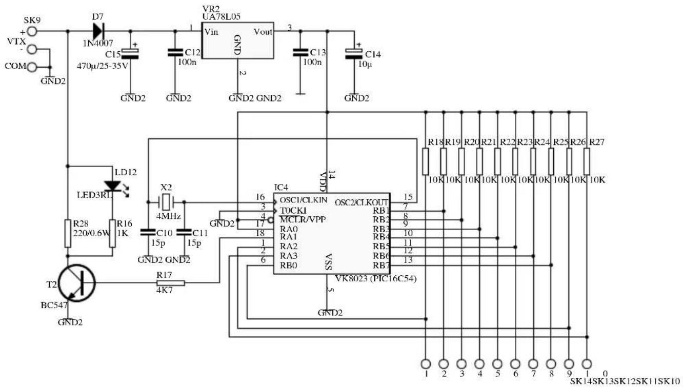
Both PCBs are connected to each other by means of two wires, VTX+ and VTX-. They supply power to the control board and carry the data signal. This signal contains information regarding the status of the 10 inputs. Filtering and regulating of the power supply is performed by VR2, together with C15, C12, C13 and C14, which also suppress possible oscillation of the voltage regulator.
The micro controller continuously monitors the status of the inputs, and switches T2 according to a custom developed serial protocol. This allows a current to flow in the VTX wires. LD12 also lights allowing you to check the operation of the system.
2. Receiver section (P8023R):
The receiver end also contains a power supply section. Diodes D1 to D4 rectify the incoming power. Voltage regulator VR1 and the surrounding capacitors make sure the control part receives a regulated 10V. From this 10V, R12, ZD1 and C8 derive 5V DC to supply the microcontroller. The actual receiving part consists of D6, D7, R14, R15 and T1. The current variations in the VTX-lines cause a voltage drop over R15, which is filtered by C3 and amplified by T1, before it is fed to the micro controller. Reception is indicated by LD11. The microcontroller analyses the serial signal, and puts the corresponding outputs high or low. Because the microcontroller cannot sink large currents, we added IC2 and IC3, which provide open collector outputs.
15. Hook-up Examples
- Connecting the K8023 to the K6714, relais card.
P6714

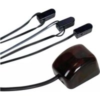
2. Connecting the K8023 to the K6711, IR receiver.
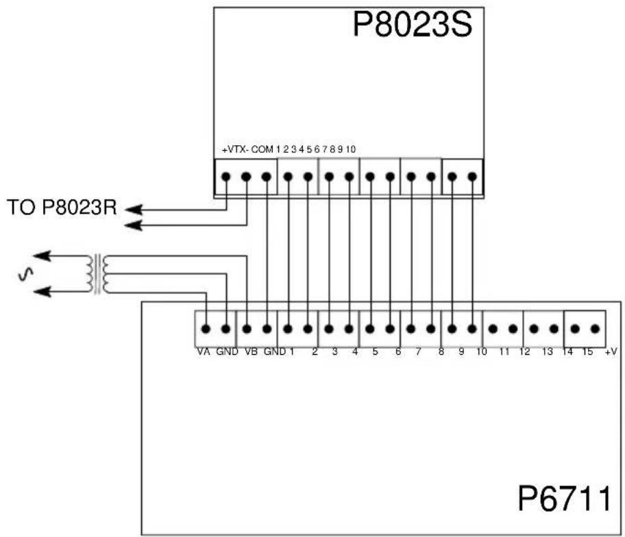
3. Connecting the K8023 to the K8006, modular light system.

4. Connecting the K8023 to the K8000, computer interface card.
P8000
Computer Interface Board

16. Schematic diagram (Control section)
- Schematic diagram (Receiver section)

18. Control PCB
19. Receiver PCB


natural_image
Interior view of a retail store with shelves stocked with products and customers at workstations (no visible text or signage)
natural_image
Abstract line drawing of two human heads facing each other with a central geometric symbol (no text or symbols present)VELLEMAN NV
Legen Heirweg 33, B-9890 GAVERE
Belgium (Europe)

@velleman_RnD
Modifications and typographical errors reserved © Velleman nv. H8023IP'1 - 2014 (rev1)



- Channel, 2-Wire REMOTE CONTROL
- K8023
- Features:
- Specifications:
- Assembly (Skipping this can lead to troubles!)
- Make sure you have the right tools:
- For some projects, a basic multi-meter is required, or might be handy
- Assembly Hints :
- Assembly of the receiver PCB : P8023R
- Assembly of the receiver PCB : P8023S
- IC socket, Watch the position of the notch!
- Electrolytic capacitor. Watch the polarity!
- Quartz crystal
- Screw connectors
- Electrolytic capacitor. Watch the polarity!
- IC mounting
- Hook - up & Testing
- Operation
- Control section (P8023S):
- Receiver section (P8023R):
- Hook-up Examples
- Connecting the K8023 to the K6711, IR receiver.
- Connecting the K8023 to the K8006, modular light system.
- Connecting the K8023 to the K8000, computer interface card.
- Schematic diagram (Control section)
- Control PCB
- Receiver PCB
Brand : VELLEMAN
Model : K8023
Category : Remote control