GW20852 - Thermostat Gewiss - Free user manual and instructions
Find the device manual for free GW20852 Gewiss in PDF.
| Product type | Electric thermostat summer/winter |
| Brand | Gewiss |
| Model | GW20852 |
| Power supply | 230 V~ 50/60 Hz |
| Output type | Relay with changeover contact 8(2)A / 250 V~ |
| Connection | 2 or 3 wires |
| Maximum wire cross-section | 2.5 mm² |
| Insulation type | Class II |
| Protection degree | IP30 |
| Adjustment range | +5°C to +30°C |
| Thermal gradient | max. 1K/15 min. |
| Differential operation | 0.7°C |
| Reading accuracy | ±1°C |
| Operating temperature | 0°C to +50°C |
| Main functions | Summer/winter switching, night reduction (-4°C), load indicator light |
| Load indicator | LED (on = load activated) |
| Remote control input | Yes (terminals 6 and 7) for night reduction |
| Installation | Recommended height 1.50-1.70 m, away from heat sources |
| Maintenance and cleaning | Clean with a soft, dry cloth. Do not use abrasive products. |
| Safety | Installation by qualified personnel, disconnect power before intervention, comply with CE standards (EMC and LVD) |
| Spare parts and repairability | Contact GEWISS after-sales service (SAT) |
| Standards | EMC EN55014-1, EN55014-2, EN61000-3-2, EN61000-3-3; LVD EN60730-1, EN60730-2-9 |
| Disconnection type | 1 B / Electronic |
Frequently Asked Questions - GW20852 Gewiss
User questions about GW20852 Gewiss
0 question about this device. Answer the ones you know or ask your own.
Ask a new question about this device
Download the instructions for your Thermostat in PDF format for free! Find your manual GW20852 - Gewiss and take your electronic device back in hand. On this page are published all the documents necessary for the use of your device. GW20852 by Gewiss.
USER MANUAL GW20852 Gewiss
natural_image
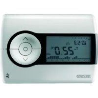
Close-up of a portable electronic device control panel with rotary dial and indicator lights (no readable text or symbols)GW 20 852 - GW 21 852
natural_image
Two identical remote control devices with black X-shaped warning signs, no text or symbols present.natural_image
Pure electrical circuit lines without any symbols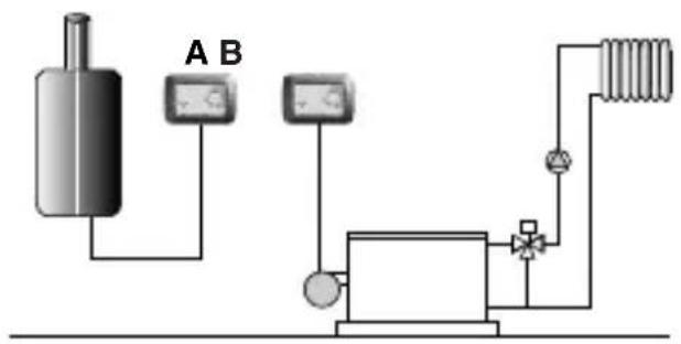
text_image
A B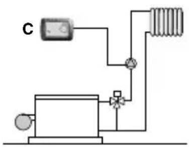
natural_image
Pure electrical circuit lines without any symbols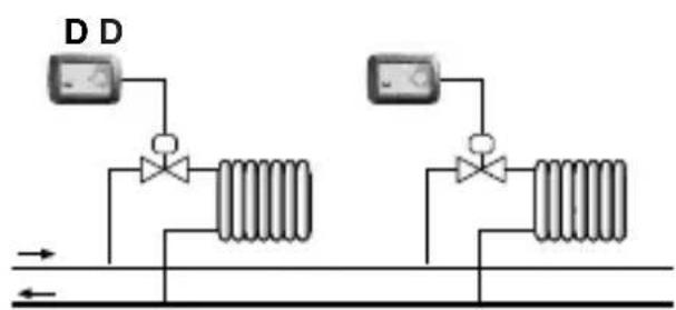
text_image
D Dtext_image
Diagram of a remote control panel with labeled buttons and a dial, showing thermal input and display settings.Electronic summer/winter thermostat
ATTENTION - IMPORTANT
- Congratulations for having choosing a Gewiss product. Gewiss products are constructed with careful attention to detail, using only high quality materials. Gewiss products assure you of peak performance over time.
- Carefully read the following instructions since they contain important information on installing and operating the product. The installer should give these instructions to the final user and ask him to read the contents.
- System programming products must be installed in conformity with the provisions of ÖD 384 - ÜEC364 regulations for devices for household or similar use in non-dusty rooms or where special protection against water penetration is not required.
- Ün case of failure and/or malfunction, contact an authorized technician or GEWÜSS SAT technical assistance service.
INDEX
page
• GENERAL PRODUCT DESCRIPTION
- zunctions ....12
• INSTALLATION INSTRUCTIONS
-äocation advice 13
- yelectrical connections 14
• OPERATING INSTRUCTIONS
- wommands and signals 16

PERFORMANCE DATA
• Function summer / winter
- äuminous signals: äed indicating load on/off
- Remote control input for night-time lowering of heating (winter). (eight-time lowering is not possible for summer conditioning)
- eight time reduction temperature (referring to set): -4^

TECHNICAL SPECIFICATIONS
• Power supply: 230 V\~ 50÷60 Öz
- Type of disconnection and appliance: 1 B / Electronic
- Type of relay output: with exchange contact èê/Cêé/èC 8(2)A / 250 V\~
- User connections (load): 2 or 3 wires
- éax. wire section at the terminals: 2.5 mm ^2
- Type of insulation: Class ÜÜ ☐
• Grade of protection: ÜP 30
- Pollution: èormal
• Regulation range: from +5°C to +30°C
• Thermal gradient: max 1 à/15 min.
• Differential operation: t = 0.7^
- Precision of reading: ± 1^
• Temperature operating limits: 0°C to +50°C
- Reference standards for CE marking:
EéC Eè55014-1 Eè55014-2 Eè61000-3-2 Eè61000-3-3
äVD Eè60730-1 Eè60730-2-9
(Directive 89/336/CEE - 7323/CEE)
INSTALLATION INSTRUCTIONS
LOCATION ADVICE
text_image
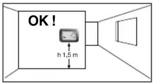
OK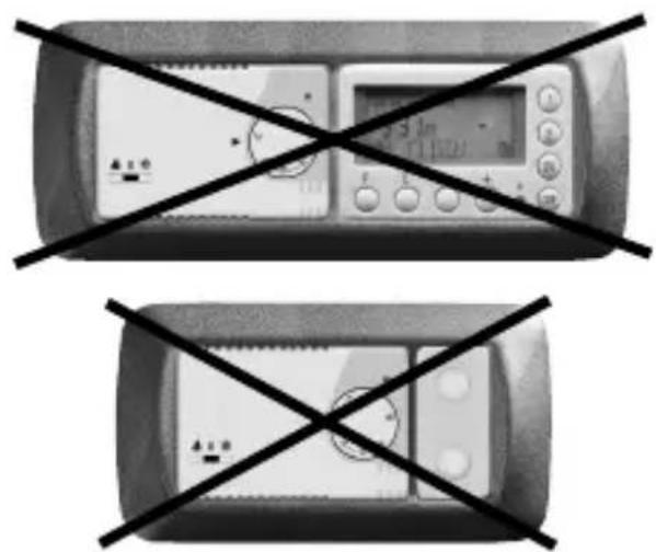
natural_image
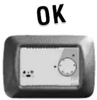
Two identical remote control devices with black X-shaped prohibition signs on their sides (no text or symbols on devices)Recommendations for positioning:
Ünstall the thermostat at a height of approx. 1.50÷1.70 m from floor level, away from heat sources, draughts, doors and windows.
text_image
OK! h 1,5 m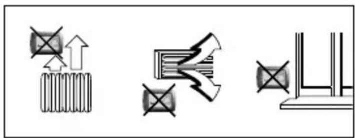
natural_image
Pure electrical circuit lines without any symbols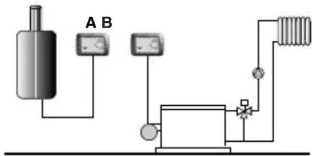
text_image
A B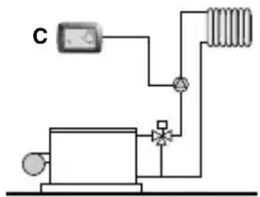
text_image
C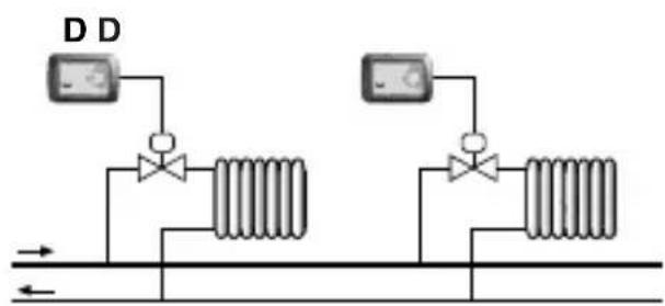
text_image
D DÖeating systems with thermostat controlling:
A Wall mounted boiler
B Burner
C Circulation pump
D Zone solenoid valve
N.B.: The examples given in the following documentation are for illustrative purposes only.
Important: The installation and electrical connecting of the devices and appliances must be undertaken by qualified personnel and in accordance with standards and regulations in force at the time. The manufacture declines to accept any responsibility concerning the use of the products in accordance with particular environmental or installation regulations, as this responsibility rests entirely with the installer.
Warning: Prior to installing the product, ensure the mains electrical supply is disconnected.
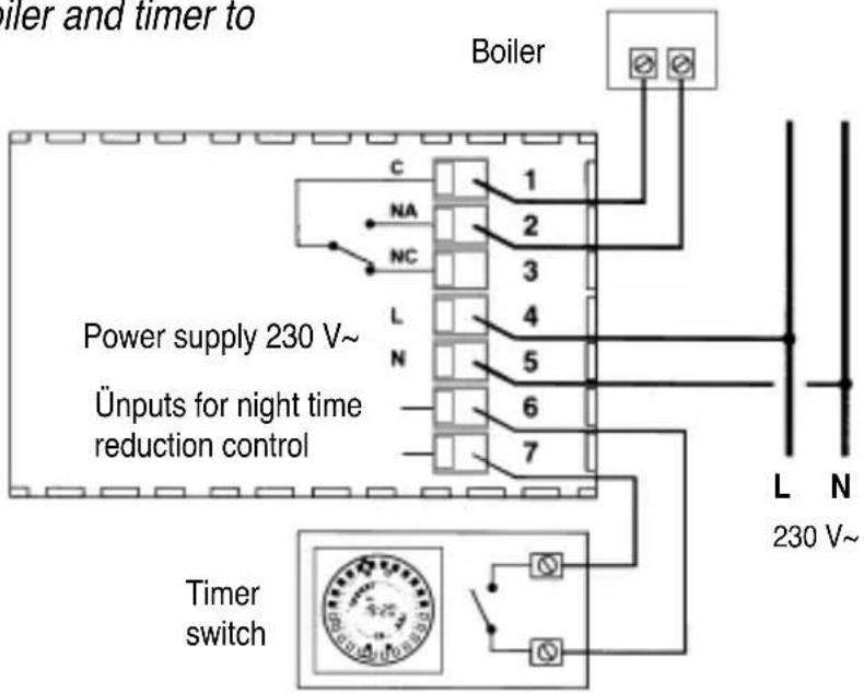
With the mains power supply disconnected:
Connect the power supply cables to terminals è° 4 (äine) and è° 5 (èeutral).
Connect the wires of the device to be controlled to terminals: n^ 1 = common
n^ 2 = norm. open
n^ 3 = norm. closed
With strong inductive loads (pumps and solenoid valves) it is recommended that an RC filter is connected in parallel to the load.
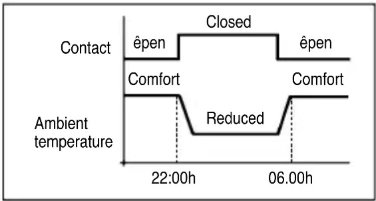
Remote selection of "Comfort" or "Reduced" temperature
Whenever it is desired to utilise the remote selection of "Comfort" or "Reduced" temperature, connect the external contact to terminals è° 6 and è° 7 of the thermostat.
other
| Time | Condition | Value | | -------- | --------- | ----- | | 22:00h | Contact | Open | | 22:00h | Comfort | Closed| | 06:00h | Comfort | Reduced| | 06:00h | Contact | Open | | 06:00h | Comfort | Closed|"Comfort" temperature = external contact open
"Reduced" temperature = external contact closed
Selection of “Reduced” temperature results in a 4^ C reduction with respect to the set temperature.
Example of connections to a boiler and timer to control night time reduction
text_image
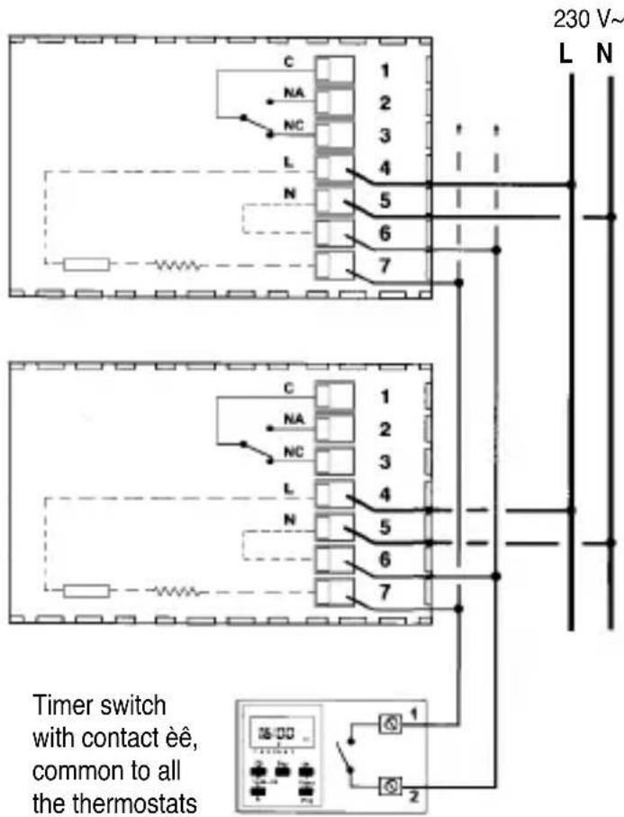
Boiler and timer to C 1 NA 2 NC 3 L 4 N 5 6 7 Boiler Power supply 230 V~ Inputs for night time reduction control Timer switch L N 230 V~ Q QMultiple installations
Un multiple installations (offices, schools, homes, etc.) where the night time reduction is controlled from a single centralised timer, in addition to the above it is necessary to pay close attention to the following instructions:
1) Power supply 230V\~
Terminal 4: connect to mains äine (230V\~)
Terminal 5: connect to mains èeutral (return)
N.B.: normally with civil mains power supplies “brown” is the recognised colour for phase and “blue” for neutral (line return).
2) Connections for night time reduction
All terminals 6: connect in parallel with output 2 of the timer.
All terminals 7: connect in parallel with output 1 of the timer.
text_image
230 V~ L N C 1 NA 2 NC 3 L 4 N 5 6 7 Timer switch with contact èê, common to all the thermostats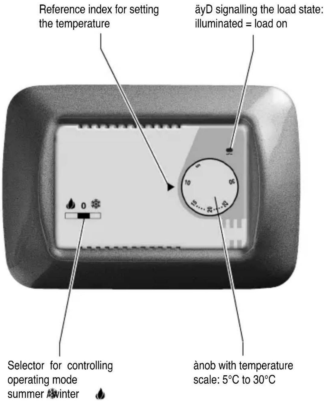
text_image
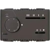
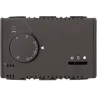
Reference index for setting the temperature äyD signalling the load state: illuminated = load on Selector for controlling operating mode summer / winter änob with temperature scale: 5°C to 30°CGEWISS
FRANÇAIS
natural_image
Front view of a vintage electronic device with a rotary knob and indicator lights (no visible text or symbols)
natural_image
Black and white photo of a device with a crossed-out X mark, no visible text or symbols
natural_image
Top-down view of a vehicle with a cross symbol crossed out, indicating no visible text or symbols on the vehicle itself.natural_image
Pure electrical circuit lines without any symbols
text_image
A B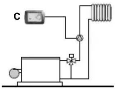
text_image
C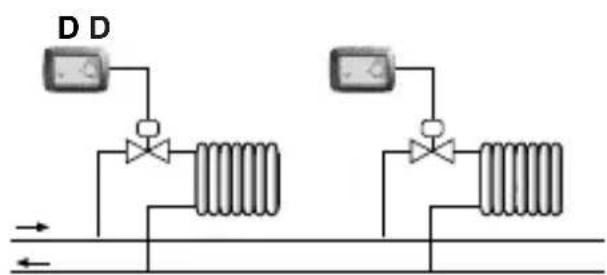
text_image
D Dtext_image
Diagram of a remote control panel with labeled buttons and a dial, showing settings like 0, 10, 20, and 30.natural_image
Front view of a vintage electronic device with a rotary knob and indicator lights (no visible text or symbols)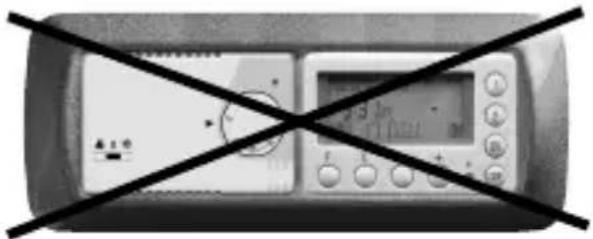
natural_image
Black and white photo of a handheld electronic device with a screen and control buttons crossed out by a diagonal line (no visible text or symbols)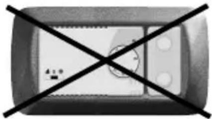
natural_image
Top-down view of a vehicle with a black X-shaped cross mark indicating no intersection or constraint (no text or symbols)natural_image
Pure electrical circuit lines without any symbols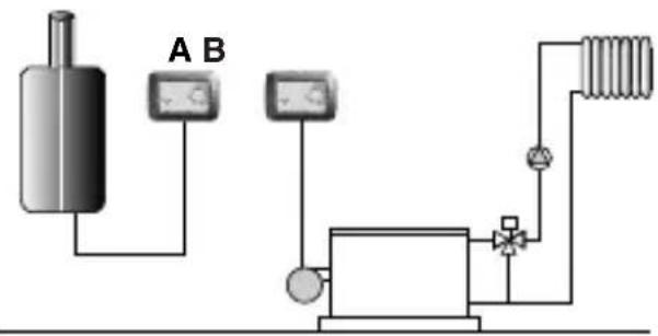
text_image
A B
natural_image
Pure electrical circuit lines without any symbols
text_image
D Dtext_image
Diagram of a remote control panel with labeled buttons and a dial, showing thermal input and display settings.natural_image
Two identical remote control devices with black X-shaped prohibition signs on their faces (no text or symbols present)natural_image
Pure electrical circuit lines without any symbols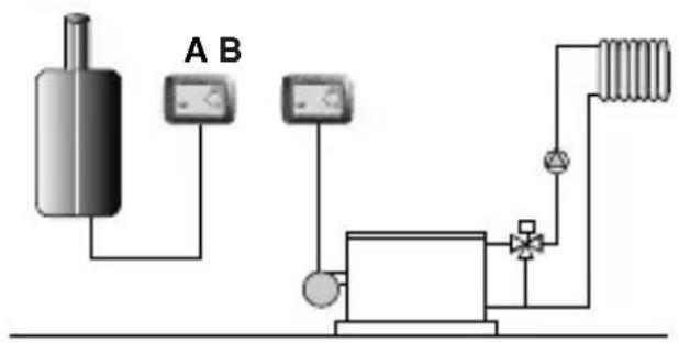
text_image
A B
text_image
C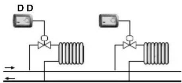
text_image
D D → ←Date of installation
Room in which installed
äocal de l'installation
Installer's stamp and signature