
GW10791 - Thermostat Gewiss - Free user manual and instructions
Find the device manual for free GW10791 Gewiss in PDF.


| Brand | Gewiss |
| Model | GW10791 |
| Product Type | Electronic Thermostat |
| Dimensions (H x W x D) | 86 x 86 x 30 mm |
| Weight | 150 g |
| Power Supply | 2 x AA batteries (1.5 V) |
| Battery Life | Approximately 1 year |
| Display Type | LCD with backlight |
| Temperature Range | 5 °C to 35 °C |
| Temperature Accuracy | ±0.5 °C |
| Programming | 7-day programmable, up to 4 time periods per day |
| Heating/Cooling Control | ON/OFF or PID regulation |
| Wireless Connectivity | None (standalone) |
| Mounting | Wall-mounted (screws included) |
| Color | White |
| Material | ABS plastic |
| Protection Rating | IP20 |
| Maintenance | Clean with a soft, dry cloth. Do not use water or cleaning agents. |
| Safety Features | Low battery indicator, over temperature protection |
| Spare Parts | Batteries, wall mounting plate, screws |
| Repair | No user-serviceable parts. Refer to qualified technician. |
Frequently Asked Questions - GW10791 Gewiss
User questions about GW10791 Gewiss
0 question about this device. Answer the ones you know or ask your own.
Ask a new question about this device
Download the instructions for your Thermostat in PDF format for free! Find your manual GW10791 - Gewiss and take your electronic device back in hand. On this page are published all the documents necessary for the use of your device. GW10791 by Gewiss.
USER MANUAL GW10791 Gewiss
KNX timed thermostat - wall mounting
CE
KNX®

GW 10 791 - GW 14 791
Technical Manual
Summary
1 Introduction....3
2 Application 3
2.1 Limits to the associations.... 3
3 "Main" menu....4
3.1 Parameters 4
3.2 Communication objects 7
4 "Load control" menu....10
4.1 Parameters 10
4.2 Communication objects 11
5 "Control algorithm (1 bit)" menu.... 13
5.1 Parameters 13
5.2 Communication objects 15
6 "Control algorithm (1 byte)" menu.... 16
6.1 Parameters 16
6.2 Communication objects 18
7 "Temperature setpoint" menu 19
7.1 Parameters 19
7.2 Communication objects 19
8 "External sensor" menu 20
8.1 Parameters 20
8.2 Communication objects 21
9 "Reports" menu....22
9.1 Parameters 22
9.2 Communication objects 24
10 "Scenes" menu 26
10.1 Parameters 26
10.2 Communication objects 27
11 "Slave control" menu....28
11.1 Parameters 28
11.2 Communication objects 30
1 Introduction
This manual describes the functions of the device named GW1x791 and how to use the ETS configuration software to change the settings and configurations.
2 Application
The KNX wall timed thermostat is a device that manages the HVAC system. It is able to regulate the temperature in the environment in which it is installed, using the KNX system to manage the actuators that control the solenoid valves, boilers etc that comprise the heating and air-conditioning systems. This device, combined with the KNX wall Thermostat, can regulate the temperatures per zone and act as a master device when a master-slave system is setup.
The device manages two operating types (HEATING and AIR CONDITIONING), and controls both systems whilst providing 5 different operating modes for each operating type (AUTO/ECONOMY/PRECOMFORT/COMFORT/OFF), each with its own customisable setpoint. The AUTO operating mode defined by default on the device is defined as BUILDING PROTECTION mode in the KNX standard.
The AUTO operating mode foresees that the device regulates the temperature in the environment where it is installed according to an internally programmed timer profile; a weekly timer profile can be configured on the device where you can define the device operating mode for every day of the week, with a 15 minute resolution and no restrictions on variations; if the device is connected to one or more thermostats in a master-slave configuration setup, it will automatically notify the slave devices of the operating modes they must enable.
The device is always able to autonomously manage the temperature in the environment it is installed in, using control algorithms (two point or proportional) which depend on the type of system built.
It is however only able to manage the heating and air conditioning system if it is a 4-way configuration as it is designed to manage one actuator for the heating system and another for the air-conditioning system. This manual refers solely to the configuration using the ETS software. Please refer to the INSTALLATION AND USER MANUAL supplied with the product for instructions on how to use the internal menu and the various local key functions.
2.1 Limits to the associations
The maximum number of logical associations that the device is able to memorize is 115; this means that the maximum number of logical connections between communication objects and group addresses is 115.
The maximum number of group addresses that the device is able to memorize is 115; this means that it is possible to associate the communication objects to a maximum of 115 group addresses.
3 "Main" menu
The Main menu lists all the parameters needed to configure the behaviour of the device in HVAC systems (see Fig. 3.1).
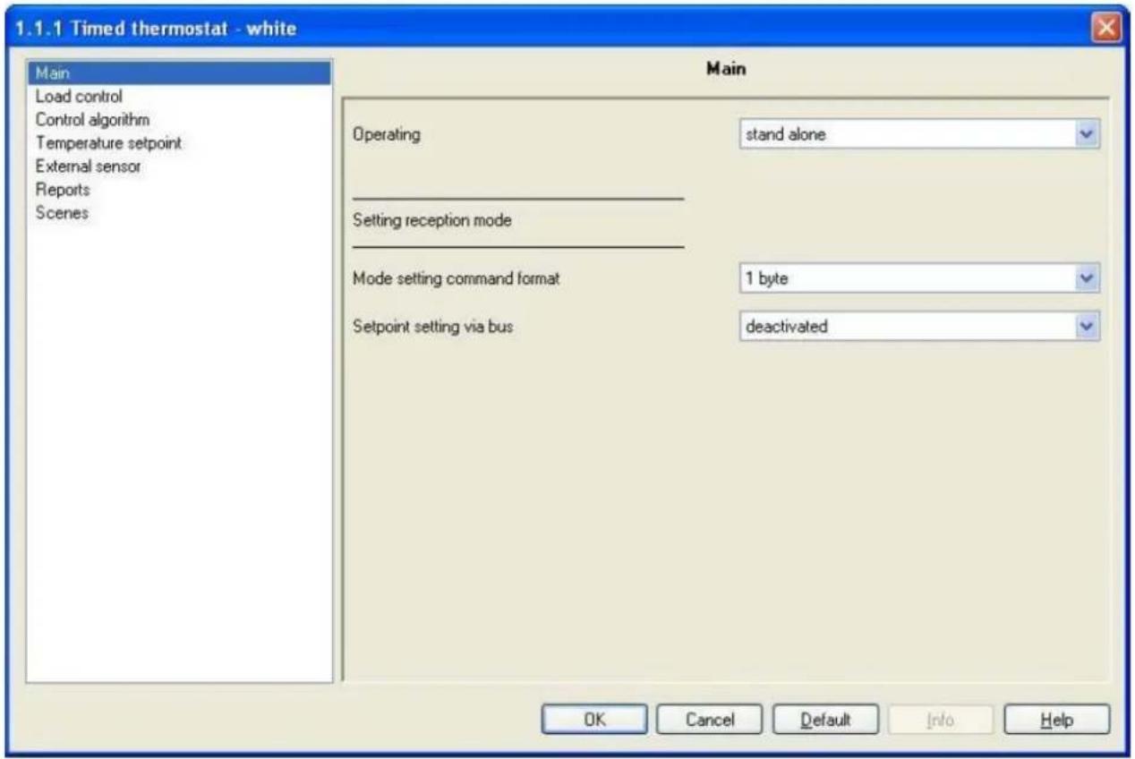
Fig. 3.1
3.1 Parameters
3.1.1 Operating
This allows you to configure how the device is used; the settings are:
- stand alone
The device manages the HVAC system in stand alone mode, i.e. without the use of thermostats to control parts of the system. This configuration foresees one single ambient temperature control centre.
- master
The device manages the HVAC system using the thermostats. With this configuration the device does not control the entire system, but only a part of it, called a zone, whilst thermostats are installed which control each a specific zone; in this case the timed thermostat not only controls the ambient temperature where it is installed, but it also communicates to the thermostats it is associated with, the operating modes to be performed, as set by the operator. When using this master-slave type configuration, simply change the operating mode on the master device, in this case the timed thermostat, to make sure the settings are sent to the slave devices (thermostats) directly by the master device that controls their functions.
When this value is selected, the new Slave control menu appears, which will be analysed later on in Chapter 11 Slave Control Menu.
3.1.2 Mode setting command format
Here you can configure the command format used to remotely control the device operating mode. Whatever setting is entered for the Operating option, it is always possible to remotely set the operating mode and operating type for the device; this means that any device is able to send a "set operating mode" and "operating type" command can control the timed thermostat from the bus without the need for direct intervention on the device to perform this type of operation. Whilst the operating type has only one command format, the operating mode option can be set in two different ways. The settings are:
- 1 byte
Here you can configure the remote control of the operating mode of the device by bus telegrams sent to a single communication object with a 1 byte format. With this setting enabled, the HVAC mode input communication object becomes visible (see 3.2.3 for further details).
- 1 bit
Here you can configure the remote control of the operating mode of the device by bus telegrams sent to a series of communication objects with a 1 bit format; to be precise, one per mode. With this setting enabled, the Off mode input, Economy mode input, Precomfort mode input, Comfort mode input and Auto mode input communication objects become visible (see 3.2. for further details). There is priority when using these communication objects, that will be illustrated at the end of the paragraph. In this case, to enable an operating mode with a lower priority compared to the current mode, it is necessary to enable the new mode and disable the one with higher priority; the device will not perform this operation automatically.
- both
It is possible to configure the remote control of the operating mode of the device by bus telegrams sent to a single communication object with a 1 byte format or to a series of communication objects with a 1 bit format; to be precise, one per mode. With this setting enabled, the HVCA mode input, Off mode input, Economy mode input, Precomfort mode input, Comfort mode input and Auto mode input communication objects become visible (see 3.2. for further details). There is priority when using these communication objects, that is illustrated below.
There is a priority among the communication objects which set the operating modes for the device by remote bus commands, that prevents the problem of more than one object being enabled at the same time; this can be seen more clearly in the layout drawing below:

flowchart
graph TD
    A["HVAC mode input\n(1 byte)"] --> B["0"]
    C["Auto mode input\n(1 bit)"] --> D["1"]
    E["Comfort mode\ninput\n(1 bit)"] --> F["1"]
    G["Precomfort mode\ninput\n(1 bit)"] --> H["1"]
    I["Economy mode\ninput\n(1 bit)"] --> J["1"]
    K["Off mode input\n(1 bit)"] --> L["1"]
    M["Operating mode ON"] --> N["0"]
    N --> O["1"]
The above graph can be summarized as follows
| Priority Object Size | ||
| Maximum | Off mode input object | 1 bit |
| Economy mode input object | 1 bit | |
| Precomfort mode input object | 1 bit | |
| Comfort mode input object | 1 bit | |
| Auto mode input object | 1 bit | |
| Minimum | HVAC mode input object | 1 byte |
The 1 bit set mode objects all have a higher priority compared to the 1 byte set mode objects; this is due to the fact that, when enabling both the set mode options, the 1 bit objects can be used to set the mode when specific events occur, such as for instance the window contact function, that is when a window is opened the device contact that controls this condition generates the bus command that forces the timed thermostat into OFF mode; when the window is closed again, this will generate a disable OFF mode command and the timed thermostat will return to its previous condition.
There is naturally a run command priority among the 1 bit set mode objects too, especially as if only 1 bit format is used to set the operating modes, if more than one object was enabled at any time, it would be necessary to determine which of these has priority to determine the operating mode enabled on the device; to therefore enable an operating mode with a lower priority than the current mode, it is necessary to enable the new mode and disable the current mode with the higher priority.
3.1.3 Setpoint setting via bus
This allows you to enable the communication objects required to configure the setpoints for each device operating mode by bus telegram; the settings are:
- deactivated
It is not possible for the bus telegrams to change the HVAC mode setpoints; no communication object is therefore visible for the setpoint configuration.
- active
It is possible to change the HVAC mode setpoints by bus telegrams; with this setting the Heating antifreeze setpoint, Heating economy setpoint, Heating precomfort setpoint, Heating comfort setpoint, Air cooling high temp. protect. setpoint, Air cooling economy setpoint, Air cooling precomfort setpoint and Air cooling comfort setpoint are all visible (see 3.2); these can be used to set the setpoints for each device operating mode by bus command.
Please remember that among the various setpoints belonging to the same operating type, there is a setting value threshold determined from what seen below:
- T_antifreeze ≤ T_economy ≤ T_precomfort ≤ T_comfort in heating ("T" indicates the standard mode setpoint value)
- T_comfort ≤ T_precomfort ≤ T_economy ≤ Thigh temp. protect. in air conditioning ("T" indicates the standard mode setpoint value)
Whilst a control is made over the modifications to setpoints from the local menu to make sure the threshold is not exceeded, the settings triggered by the bus do not undergo the same control to prevent that, if a supervisor updates a series of parameters, there will be no need to establish an order in which to make the updates to the various setpoints; however, the operator is requested to avoid setting setpoints for bus commands that do not comply with the above threshold as this could cause the device to malfunction.
3.2 Communication objects
The communication objects, whose visibility depends on the settings in the items of the Main menu, are those indicated in Fig. 3.2.
| Number | Name | Object Function | Length | C | R | W | T | U | Data Type | Priority |
| 0 | Day/Hour input | Update day/hour | 3 Byte | C | - | W | - | - | Time DPT_TimeOfDay | Low |
| 1 | Operating type input | Heating/Air conditioning | 1 bit | C | - | W | - | - | Low | |
| 2 | HVAC mode input | Auto/Eco/Precom/Comf/Off | 1 Byte | C | - | W | - | - | Low | |
| 3 | Off mode input | Enable/Disable | 1 bit | C | - | W | - | - | 1 bit DPT_Enable | Low |
| 4 | Economy mode input | Enable/Disable | 1 bit | C | - | W | - | - | 1 bit DPT_Enable | Low |
| 5 | Precomfort mode input | Enable/Disable | 1 bit | C | - | W | - | - | 1 bit DPT_Enable | Low |
| 6 | Comfort mode input | Enable/Disable | 1 bit | C | - | W | - | - | 1 bit DPT_Enable | Low |
| 7 | Auto mode input | Enable/Disable | 1 bit | C | - | W | - | - | 1 bit DPT_Enable | Low |
| 8 | Heating antifreeze setpoint | Setpoint value | 2 Byte | C | - | W | - | - | 2 byte float value DPT_Value_Temp | Low |
| 9 | Heating economy setpoint | Setpoint value | 2 Byte | C | - | W | - | - | 2 byte float value DPT_Value_Temp | Low |
| 10 | Heating precomfort setpoint | Setpoint value | 2 Byte | C | - | W | - | - | 2 byte float value DPT_Value_Temp | Low |
| 11 | Heating comfort setpoint | Setpoint value | 2 Byte | C | - | W | - | - | 2 byte float value DPT_Value_Temp | Low |
| 12 | Air cooling high temp. protect. setpoint | Setpoint value | 2 Byte | C | - | W | - | - | 2 byte float value DPT_Value_Temp | Low |
| 13 | Air cooling economy setpoint | Setpoint value | 2 Byte | C | - | W | - | - | 2 byte float value DPT_Value_Temp | Low |
| 14 | Air cooling precomfort setpoint | Setpoint value | 2 Byte | C | - | W | - | - | 2 byte float value DPT_Value_Temp | Low |
| 15 | Air cooling comfort setpoint | Setpoint value | 2 Byte | C | - | W | - | - | 2 byte float value DPT_Value_Temp | Low |
Fig. 3.2
3.2.1 Daily/Hour input
The device is able to update the date and time on its internal clock when it receives a bus telegram. It is however possible to update the date and time using the local navigation menu on the device.
The enabled flags are C (communication) and W (written by bus)
The standard format of the object is 10.001 DPT_TimeOfDay, so the size of the object is 3 byte and the information it receives is update day/hour.
3.2.2 Operating type input
Here you can configure the remote control of the device function type by bus command. When this communication object receives a telegram with "1" a logic value, the device sets the operating type to Heating, indicated by a pilot light on the display, maintaining the same operating mode as before; vice versa, when this communication object receives a telegram with a "0" logic value, the device sets the operating type to Air conditioning, indicated by a pilot light on the display, maintaining the same operating mode as before.
It is however possible to modify the operating type using the local navigation menu on the device.
The enabled flags are C (communication), W (written by bus).
The standard format of the object is 1.100 DPT_Heat/Cool, so the size of the object is 1 bit and the commands it receives are operating type commands: Heating/Air conditioning.
3.2.3 HVAC mode input
Here you can configure the remote control of the device operating mode (or HVAC mode) by bus command. When this communication object receives a telegram from the bus with the operating mode information that is to be set, the device sets the operating mode according to the command received, indicated by a pilot light on the display, only if there are no 1 bit operating mode objects enabled.
It is however possible to modify the operating mode using the local navigation menu on the device, which does nothing more than replicate the command reception event on the communication object in question to modify, with each pressing, the operating mode.
The enabled flags are C (communication), W (written by bus).
The standard format of the object is 20.102 DPT_HVACMode, so the size of the object is 1 byte and the commands it receives are Operating mode commands: Auto/Economy/Precomfort/Comfort/Off.
3.2.4 Off mode input
Here you can enable the remote control of the device OFF operating mode (or HVAC mode) by bus command. When this communication object receives a telegram with a "1" logic value, the device instantly switches to OFF mode, indicated by a pilot light on the display, given the enabling of this object has a higher priority than any other HVAC setting; vice versa, when this communication object receives a telegram with a "0" logic value, the device instantly disables the OFF operating mode and the new operating mode is enabled automatically by the device according to the priority table illustrated in paragraphs 3.1.2.
Please remember that, in this case, until the OFF operating mode is disabled, it is not possible to modify the operating mode using the local navigation menu on the device, as the latter does nothing more than replicate the command reception event on the HVAC mode input communication object which has a lower priority than the object in question.
The enabled flags are C (communication), W (written by bus).
The standard format of the object is 1.003 DPT_Enable, so the size of the object is 1 bit and the commands it receives are enable/disable OFF operating mode commands.
The above described features and functions also apply to the Economy mode input, Precomfort mode input, Comfort mode input and Auto mode input communication objects, so please refer to the description provided in 3.2.4, the difference being that reference is made to the relative operating modes. The priority table illustrated in paragraph 3.1.2. remains the same.
3.2.5 Heating antifreeze setpoint
Here you can configure the remote control by bus command of the OFF mode setpoint for the HEATING operating type; if this communication object receives an enable setpoint telegram with a value of less than 2^ C and more than 40^ C, the command will be ignored for safety reasons. However, the setpoint for this mode must be between 2^ C and 7^ C and also lower than the setpoint value set for the ECONOMY mode (see paragraph 3.1.3) and, if a value is received that does not respect these thresholds, the value will become effective until the local navigation menu is accessed; once you access the setpoint parameters on the local menu, the device controls that all the setpoint thresholds are complied with and, if this is not the case, the device will automatically modify the setpoint so that it complies with the configuration threshold.
It is however possible to modify the HEATING mode OFF setpoint at any time using the local navigation menu on the device.
The enabled flags are C (communication), W (written by bus).
The standard format of the object is 9.001 DPT_Value_Temp, so the size of the object is 2 byte and the commands it receives are HEATING mode OFF mode setpoint values expressed in degrees centigrade (rounded off to a tenth of a degree).
The above described features and functions also apply to the following objects: Heating economy setpoint, Heating precomfort setpoint, Heating comfort setpoint, for the HEATING mode and the Air cooling high temp. protect. setpoint, (equivalent to OFF mode) Air cooling economy setpoint, Air cooling precomfort setpoint and Air cooling comfort setpoint for the AIR CONDITIONING mode, so please refer to the description provided in 3.2.5, the difference being that reference is made to the relative operating modes.
The setpoint thresholds illustrated in paragraph 3.1.3. remain the same.
4 "Load control" menu
The Load control menu lists all the parameters used to set the format of commands sent to the controlled loads (Fig. 4.1); according to the setting entered for this option, the load control algorithms that can be configured in the Control algorithm menu will change, and consequently the conformation of the actual menu.

Fig. 4.1
4.1 Parameters
4.1.1 Command format
Here you can configure the format for the communication objects that control the loads, and also the control algorithms that allow the loads to be managed; the settings are:
- 1 bit (0/1)
The format of the communication objects that manage the loads is 1 bit; here you can configure the load control algorithms (see Chapter 5) as follows: 2 on/off and PMW proportional points. The Heating switching and Air cooling switching communication objects are visible and allow the loads to be controlled.
- 1 byte (% value)
The format of the communication objects that manage the loads is 1 byte; here you can configure the load control algorithms (see Chapter 6) as follows: 2 0%/100% and continuous proportional points.
The Heating continuous command and Air cooling continuous command communication objects are visible and allow the loads to be controlled.
4.1.2 Controlled actuators feedback
This allows you to enable the device so it can receive feedback from the actuators (loads) it controls; the settings are:
- disabled
The device is not able to receive confirmation from the actuators (loads) that the command sent has actually been performed; the Command repetition period on feedback missing option appears which allows you to enter a repetition period for the load commands.
- enabled
The device is able to receive confirmation from the actuators (loads) that the command sent has actually been performed; the Heating status feedback (see 4.2.1) and the Air cooling status feedback (see 4.2.2) communication object are visible if the Command format option is set to 1 bit (0/1) whilst if this option is set to 1 byte (% value) the Heating continuous control feedback (see 4.2.5) and the Air cooling continuous control feedback (see 4.2.6) communication objects are visible.
On setting this value, the Command repetition period on feedback missing option is not visible as the device is always aware of the status of the loads it commands; in fact, if within one minute from sending a command to a load, the latter does not send confirmation of execution of the command to the timed thermostat, it will send the command again every minute until it receives due confirmation from the load; the heating/air conditioning system pilot light will blink to signal this anomaly.
4.1.3 Command repetition period on feedback missing
Here you can set the retransmission period of the command to the loads; the settings are provided in the drop-down menu (an interval of from 5 minutes to 30 minutes).
4.2 Communication objects
The communication objects, whose visibility depends on the settings in the items of the Load control menu, are those indicated in Fig. 4.2.
| Number | Name | Object Function | Length | C | R | W | T | U | Data Type | Priority |
| 16 | Heating status feedback | On/Off status | 1 bit | C | - | W | - | - | 1 bit DPT_Switch | Low |
| 18 | Air cooling status feedback | On/Off status | 1 bit | C | - | W | - | - | 1 bit DPT_Switch | Low |
| 28 | Heating switching | On/Off | 1 bit | C | R | - | T | - | 1 bit DPT_Switch | Low |
| 30 | Air cooling switching | On/Off | 1 bit | C | R | - | T | - | 1 bit DPT_Switch | Low |
| 17 | Heating continuous control feedback | % Value | 1 Byte | C | - | W | - | - | 8 bit unsigned value DPT_Scaling | Low |
| 19 | Air cooling continuous control feedback | % Value | 1 Byte | C | - | W | - | - | 8 bit unsigned value DPT_Scaling | Low |
| 29 | Heating continuous command | % Value | 1 Byte | C | R | - | T | - | 8 bit unsigned value DPT_Scaling | Low |
| 31 | Air cooling continuous command | % Value | 1 Byte | C | R | - | T | - | 8 bit unsigned value DPT_Scaling | Low |
Fig. 4.2
4.2.1 Heating status feedback
This allows the device to be informed on the status of the actuator that manages the heating system controlled by the timed thermostat; once the command has been sent to this actuator, if the device does not receive confirmation within one minute that the load has executed the command by bus telegram to the communication object in question, it will instantly send the command again every minute until it receives due confirmation from the load; the heating/air conditioning system pilot light will blink to signal this anomaly (according to which is displayed on the screen). If a feedback is received by the actuator that does not copy the command sent, the device will instantly send another command and trigger the above described control.
The enabled flags are C (communication), W (written by bus).
The standard format of the object is 1.001 DPT_Switch, so the size of the object is 1 bit and the commands it receives are heating system actuator status On/Off.
4.2.2 Air cooling status feedback
The same characteristics and function apply as indicated in the previous paragraph, the different being that they refer to the air conditioning system (please refer to 4.2.1 for further details).
4.2.3 Heating switching
This allows the device to send ON/OFF commands to the actuator that manages the heating system controlled by the timed thermostat; according to the control algorithm set, the device calculates when it has to intervene on the heating system to regulate the ambient temperature and therefore sends a telegram with a "1" logic value to activate the system, and "0" logic value to deactivate it.
The enabled flags are C (communication), R (read by bus) and T (transmission).
The standard format of the object is 1.001 DPT_Switch, so the size of the object is 1 bit and the commands it sends are heating system On/Off.
4.2.4 Air cooling switching
The same characteristics and function apply as indicated in the previous paragraph, the different being that they refer to the air conditioning system (please refer to 4.2.3 for further details).
4.2.5 Heating continuous control feedback
This allows the device to be informed on the status of the actuator that manages the heating system controlled by the timed thermostat; once the command has been sent to this actuator, if the device does not receive confirmation within one minute that the load has executed the command by bus telegram to the communication object in question, it will instantly send the command again every minute until it receives due confirmation from the load; the heating/air conditioning system pilot light will blink to signal this anomaly (according to which is displayed on the screen). If a feedback is received by the actuator that does not copy the command sent, the device will instantly send another command and trigger the above described control.
The enabled flags are C (communication), W (written by bus).
The standard format of the object is 5.001 DPT_Scaling, so the size of the object is 1 byte and the commands it receives are heating system actuator percentage status.
4.2.6 Air cooling continuous control feedback
The same characteristics and function apply as indicated in the previous paragraph, the different being that they refer to the air conditioning system (please refer to 4.2.5 for further details).
4.2.7 Heating continuous command
This allows the device to send percentage regulation commands to the actuator that manages the heating system controlled by the timed thermostat; according to the control algorithm set, the device calculates when it has to intervene on the heating system to regulate the ambient temperature and therefore sends a telegram with the system activation percentage information.
The enabled flags are C (communication), R (read by bus) and T (transmission).
The standard format of the object is 5.001 DPT_Scaling, so the size of the object is 1 byte and the commands it sends are the heating system percentage values.
4.2.8 Air cooling continuous command
The same characteristics and function apply as indicated in the previous paragraph, the different being that they refer to the air conditioning system (please refer to 4.2.7 for further details).
5 "Control algorithm (1 bit)" menu
The Control algorithm menu lists all the parameters used to set the load control algorithms for the heating and air conditioning system (see Fig. 5.1); in this chapter you will find the menu and relative options when the Command format option in the Load Control menu is set to 1 bit (0/1).

Fig. 5.1
5.1 Parameters
5.1.1 Control type
Here you can set the load control algorithms applied to the heating system, given that this item is found in the heating menu (see subtitle in Fig. 5.3); the settings are:
- two points ON - OFF
The algorithm used to control the heating system is the classic algorithm defined as a two point control. This control type turns the heating system ON and OFF according to a hysteresis cycle, that is there is no single threshold that discriminates the ON and OFF command but two are identified; Fig. 5.2 illustrates this notion.

Fig. 5.2
When the measured temperature is below the “setpoint- T_ R ” value (where T_R identifies the heating regulation differential value) the device starts the heating system by sending the relative bus command to the actuator that manages it; when the measured temperature reaches the indicated setpoint value, the device switches off the heating system by sending the relative bus command.
You can see in this diagram that there are two thresholds which control the ON and OFF commands for the heating system; the first consists in the “setpoint- T_ R ” value, below which the device switches the system ON, the second consists in the indicated setpoint value, over which the device switches the system OFF.
With this setting the Regulation differential (tenth of °C) (see 5.1.2) and Thermal gradient autostoring (see 5.1.4).
• proportional PWM
The algorithm used to control the heating system is the algorithm which allows you to reduce heat inertia times caused by a two point control, called a PMW control. This control type foresees the modulation of the pulse duty-cycle, represented by the heating system activation time, according to the difference between the indicated setpoint and the detected temperature; Fig. 5.3 illustrates this notion.

Fig. 5.3
As you can see in the diagram, the device keeps the heating system ON for a percentage of time that depends on the difference between the measured temperature and the indicated setpoint; the setpoint and "setpoint- T_ R " values are indicated on the ordinate axis, that determines the proportional band limits within which the device constantly regulates the heating system, modulating the system's ON and OFF times.
With this type of algorithm there is no hysteresis cycle on the heating element and therefore the inertia time (system heating and cooling time) introduced by the two point control is eliminated. This also leads to energy savings as the system does not stay ON for no reason and, once the desired temperature has been reached, it continues to supply amounts of heat just to compensate any dispersion of heat in the environment.
With this setting the Regulation differential (tenth of °C) and Thermal gradient autostoring disappear and are replaced by new options, namely PWM regulation differential (see 5.1.3) and Cycle time (see 5.1.5).
➢ 5.1.2 Regulation differential (tenth of °C)
Here you can set the heating regulation differential value (referred to in paragraph 5.1.1) which, subtracted from the indicated setpoint value, determines the threshold value below which the heating system is switched ON upon two point control. The settings range from 2 (tenths of degrees centigrade) to 20 (tenths of degrees centigrade).
5.1.3 PWM regulation differential
Here you can set the heating PMW regulation differential value (referred to in paragraph 5.1.1) which, subtracted from the indicated setpoint value, determines the lowest limit of the proportional band limits used to modulate the times when the heating system is switched ON upon PWM proportional control. The settings are provided in the drop-down menu (an interval of from 0.4^ C to 3.2^ C).
5.1.4 Thermal gradient self-learning
This enables the thermal gradient autostoring function so that the device which operates in AUTO mode can bring the ambient temperature to full capacity before the mode switch set by the daily timer profile is implemented. The settings are:
- disabled
The device does not store the temperature in the environment and therefore does not start the heating system.
- enabled
The device (only and exclusively when running in AUTO mode and operating in HEATING mode) applies the two point control algorithm and stores the temperature in the room; it consequently starts the heating system and brings the temperature to full capacity before the HVAC mode is switched as set by the daily time profile on the device. The storing phase is performed every day, during the first mode switch that foresees an increase in the setpoint set in the timer profile.
5.1.5 Cycle time
Here it is possible to set the time within which the device must perform PWM modulation. The settings are provided in the drop-down menu (an interval of from 5 minutes to 60 minutes).
5.1.6 Control type
Here you can set the load control algorithms applied to the air conditioning system, given that this item is found in the AIR COOLING menu (see Fig. 5.1); the settings are the same as those in the example above (see 5.1.1).
As the air conditioning parameters have the same characteristics and functions, with the sole difference being that they refer to the AIR COOLING operating type, please refer to the paragraphs above (from 5.1.1 to 5.1.5) for further information.
5.2 Communication objects
There are no communication objects enabled by the Control algorithm(1bit) menu.
6 "Control algorithm (1 byte)" menu
The Control algorithm menu lists all the parameters used to set the load control algorithms for the heating and air conditioning system (see Fig. 6.1); in this chapter you will find the menu and relative options when the Command format option in the Load control menu is set to 1 byte (% value).

Fig. 6.1
6.1 Parameters
6.1.1 Control type
Here you can set the load control algorithms applied to the heating system, given that this item is found in the heating menu (see subtitle in Fig. 6.1); the settings are:
• two points 0% - 100%
The functions and characteristics are the same as those illustrated for 1 bit control algorithm therefore please refer to 5.1.1. With this setting, the Regulation differential (tenth of °C) option is visible.
• continuous proportional
The algorithm used to control the heating system is the algorithm which allows you to reduce heat inertia times caused by a two point control, called continuous control. This control type foresees the continuous control of the difference between the measured temperature and the indicated setpoint and consequently the sending of power modulation commands to the heating system; Fig. 6.2 illustrates this notion.

Fig. 6.2
The device sends the commands to the actuator that manages the heating system according to the difference between the measured temperature and the indicated setpoint; the setpoint and “setpoint- T_ R ” values are indicated on the ordinate axis, that determines the proportional band limits within which the device constantly regulates the heating system, modulating the power supplied to the same.
With this type of algorithm there is no hysteresis cycle on the heating element and therefore the inertia time (system heating and cooling time) introduced by the two point control is eliminated. This also leads to energy savings as the system does not stay ON for no reason and, once the desired temperature has been reached, it continues to supply amounts of heat just to compensate any dispersion of heat in the environment.
With this setting the Regulation differential (tenth of °C) and Thermal gradient autostoring) disappear and are replaced by new options, namely Min. variation % for send command event, PWM regulation differential and Cycle time.
➢ 6.1.2 Regulation differential (tenth of °C)
Here you can set the heating regulation differential value which, subtracted from the indicated setpoint value, determines the threshold value below which the heating system is switched ON upon two point control. The settings range from 2 (tenths of degrees centigrade) to 20 (tenths of degrees centigrade).
6.1.3 Min. % variation for command sending
Here you can set the minimum variation value for sending commands to the actuator that manages the heating system and/or the actuator that manages the air conditioning system. The settings are: 5% - 10% - 20%.
This value determines the number of proportional sub-bands within which the device determines the value of the power to be sent to the system. This means that it is necessary to pay careful attention when setting this value as, bearing in mind that the temperature measure resolution is 0.1 ^ , the sub-bands that are created cannot be lower in dimension than the resolution.
If, for instance the regulation differential value is 0.4^ C, the minimum variation for a send command event would have to be 20% (generating in this case 4 sub-bands each with a width of 0.1^ C) whilst, if the regulation differential value is 1.2^ C, the minimum variation for a send command event would have to be 10% (generating in this case 10 sub-bands each with a width of 0.12^ C).
A value of 5% can only be set where the regulation differential value is over 2°C.
Please note that this option appears when the heating and air conditioning control is switched to continuous proportional mode, and also when only one is in continuous proportional mode; in the former case, the value set for this option is applied to both operating types.
6.1.4 Thermal gradient self-learning
This enables the thermal gradient autostoring function so that the device which operates in AUTO mode can bring the ambient temperature to full capacity before the mode switch set by the daily timer profile is implemented. The settings are:
- disabled
The device does not store the temperature in the room and consequently does not start the heating system to bring the temperature to full capacity before the HVAC mode is switched as set by the daily time profile on the device.
- enabled
The device learns the temperature in the room and consequently starts the heating system to bring the temperature to full capacity before the HVAC mode is switched as set by the daily time profile on the device. The learning phase is performed every day, when the device is running in AUTO mode, during the first mode switch that foresees an increase in the setpoint set in the timer profile.
This function is only and exclusively applied when the device is running in AUTO mode and operating in HEATING mode); once the device is in these conditions, before the moment that has been set for the change mode in the daily timer with an increase of the setpoint, the device checks the measured temperature and applies the two point control algorithm; if, at a certain time, the daily timer is set to switch mode, for instance from ECONOMY to COMFORT, before the switch mode actually takes place, the device starts the system so that when the switch is made the temperature is already at the setpoint value set for COMFORT mode.
6.1.5 PWM regulation differential
Here you can set the heating proportional regulation differential value which, subtracted from the indicated setpoint value, determines the lowest limit of the proportional band limits used to modulate the power supplied to heating system upon continuous proportional control. The settings are provided in the drop-down menu (an interval of from 0.4^ C to 3.2^ C).
The settings, multiplied by the value set in the Min variation % for send command event option, determines the width of the proportional sub-band within which the device determines the power to be supplied to the system.
6.1.6 Cycle time
Here you can set the value that defines the period between the various applications of the continuous proportional control algorithm and the period for sending telegrams to the load. The settings range are provided in the drop-down menu (an interval of from 5 to 60 minutes).
Once the algorithm has been applied and the percentage power value for the heating system has been sent, this value remains in force until the cycle time ends and a new algorithm is used to calculate the new value for the power to be applied.
6.1.7 Control type
Here you can set the load control algorithms applied to the air conditioning system, given that this item is found in the AIR COOLING menu; the settings are the same as those in the example above (see 6.1.1).
As the air conditioning parameters have the same characteristics and functions, with the sole difference being that they refer to the AIR COOLING operating type, please refer to the paragraphs above (from 6.1.1 to 6.1.6) for further information.
6.2 Communication objects
There are no communication objects enabled by the Control algorithm (1 byte) menu.
7 "Temperature setpoint" menu
The Temperature setpoint menu lists all the parameters needed to configure the setpoint values for the various HVAC modes and the two different operating types (see Fig. 7.1).

Fig. 7.1
7.1 Parameters
7.1.1 Comfort setpoint
Here you can set the setpoint value for the COMFORT mode when it is HEATING operating type; the values are expressed in tenths of degrees centigrade and range from 50 (5 degrees centigrade) to 400 (40 degrees centigrade).
The restrictions listed in 3.1.3 must be complied with when setting this value.
This value can in any case be modified by the operator using the setting in the local navigation menu on the device and, where enabled, modified by a bus telegram to the relative communication object.
The above described features and functions also apply to the following parameters Precomfort setpoint, Economy setpoint, Antifreeze setpoint (equivalent to OFF mode) fur the HEATING operating type, and Comfort setpoint, Precomfort setpoint, Economy setpoint, High temperature protection setpoint (equivalent to OFF mode) for the AIR CONDITIONING operating type.
7.2 Communication objects
There are no communication objects enabled by the Temperature setpoint menu.
8 "External sensor" menu
The External sensor menu lists all the parameters needed to enable and configure the use of an auxiliary input for an external sensor, used to determine the temperature in the environment to be controlled in the various HVAC modes of the two different operating types (see Fig. 8.1).

Fig. 8.1
8.1 Parameters
8.1.1 External sensor
This is to enable the auxiliary input to measure the ambient temperature and consequently the configuration settings and the communication object which will receive the temperature value; the settings are:
- disabled
The auxiliary input is not available and the measured temperature only depends on the value measured by the sensor onboard the device.
With this configuration the Sensor incidence in the temperature calculation and Monitoring time (minutes) and the communication object External sensor input are not visible.
- enabled
The auxiliary input is available and the measured temperature depends on the value measured by the sensor onboard the device and also by the external sensor, calculated as a weighted mean of the two values.
With this configuration the Sensor incidence in the temperature calculation and Monitoring time (minutes) and the communication object External sensor input are all visible.
8.1.2 Sensor incidence in the temperature calculation
Here you can set the sensor incidence on the weighted mean used to calculate the measured temperature; the settings can be seen in the drop down menu (in an interval 10% - 100%).
The measured temperature will be calculated as the weighted mean between the value measured by the sensor onboard the device and the value measured by the auxiliary external sensor. The value set for this option allows you to specify the incidence of the value measured by the external sensor in the overall calculation of the measured temperature, which ranges from 10% to a maximum of 100% (external sensor measured value = measured temperature). The complete formula used to calculate temperature is:
$$ T _ {\text { measured }} = T _ {\text { external sensor }} \times \text { Incidence } _ {\text { external sensor }} + T _ {\text { device sensor }} \times (1 0 0 \% - \text { Incidence } _ {\text { external sensor }}) $$
8.1.3 Monitoring time (minutes)
Here you can set the time, expressed in minutes, after which the device assigns the value of the temperature detected by the device onboard sensor to the measured temperature value, without any weighted mean, if it does not periodically receive the telegram with the value measured by the external sensor.
The settings range from 2 (minutes) to 10 (minutes).
This type of configuration has been adopted to prevent any malfunctions on the external sensor from creating incorrect temperature values and consequently an incorrect management of the whole system. When the sensor sends another new value, the weighted mean will be applied again to determine the value of the measured temperature.
8.2 Communication objects
The communication object, whose visibility depends on the settings in the items of the External sensor menu, is that indicated in Fig. 8.2.
| Number | Name | Object Function | Length | C | R | W | T | U | Data Type | Priority |
| 20 | External sensor input | Sensor measured te... | 2 Byte | C | - | W | - | - | 2 byte float value DPT_Value_Temp | Low |
Fig. 8.2
8.2.1 External sensor input
This allows the device to receive bus telegrams with the temperature value measured by the auxiliary external sensor, in order to calculate the measured temperature value. Please remember that the value received by this communication object is subject to a monitoring time; when this lapses the measured temperature is determined by the sensor onboard the device only The enabled flags are C (communication), W (written by bus).
The standard format of the object is 9.001 DPT_Value_Temp, so the size of the object is 2 byte and the commands it receives are temperature values detected by external sensor expressed in degrees centigrade (rounded off to a tenth of a degree).
9 "Reports" menu
The Reports menu lists all the parameters needed to configure the send feedback settings that the device sends by bus telegram (see Fig. 9.1).
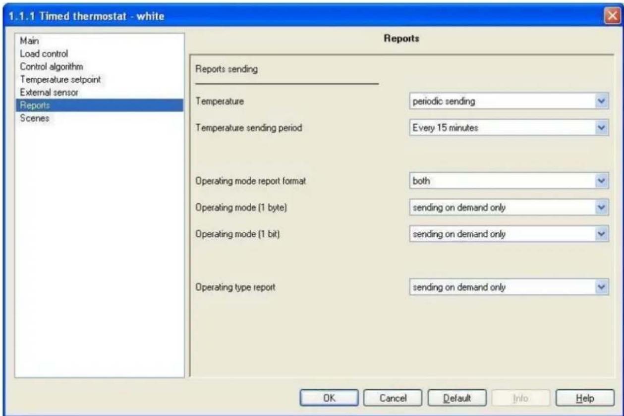
Fig. 9.1
9.1 Parameters
9.1.1 Temperature
This allows you to set the conditions for sending the measured temperature value; the settings are:
- Sending on demand only
The temperature value is not sent spontaneously by the device, but only upon receiving a status read request, when the device sends a response telegram to the applicant with the relative measured temperature value, which is that displayed on the screen. With this setting the Temperature sending period option is not visible.
- Sending on variation only (0.5 °C)
The temperature value is sent spontaneously by the device, but only if the variation in temperature compared to the last sent value is equal to at least 0.5 degrees centigrade. With this setting the Temperature sending period option is not visible.
• Periodic sending
The temperature value is sent periodically by the device, according to set intervals. With this setting the Temperature sending period option is also visible and is used to set the interval at which the measured temperature value should be sent.
9.1.2 Temperature sending period
Here you can set the interval at which the measured temperature telegrams are sent; the settings are provided in the drop-down menu (an interval of from "Every minute" to "Every 255 minutes").
9.1.3 Operating mode report format
Here you can configure the bus telegram format used by the device to notify the HVAC operating mode is enabled on the device. The settings are:
- 1 byte
The device notifies the operating mode using one single 1 byte communication object; with this configuration the Operating mode (1 byte) and the HVAC mode feedback communication object are visible.
• 1 bit
The device identifies the operating mode using series of communication objects with a 1 bit format; to be precise, one per mode. When a mode is actually enabled, it is notified by bus telegram to the object associated to the new mode, and a disabled mode feedback is sent to the object associated to the mode that was previously enabled. There are never circumstances where more than one HVAC mode is enabled at the same time. With this setting enabled, the Operating mode (1 bit) option and the OFF mode feedback, Economy mode feedback, Precomfort mode feedback, Comfort mode feedback and Auto mode feedback communication objects become visible.
- both
The device identifies the operating mode using the communication object with a 1 byte format and the communication object with a 1 bit format. With this setting enabled, the Operating mode (1 byte) and Operating Mode (1 bite) options and the HVAC mode feedback, OFF mode feedback, Economy mode feedback, Precomfort mode feedback, Comfort mode feedback and Auto mode feedback communication objects become visible.
9.1.4 Operating mode (1 byte)
Here you can configure the send conditions for the operating mode feedback through the HVAC mode feedback 1 byte communication object.
The settings are:
- sending on demand only
The operating mode feedback are not sent spontaneously by the device, but only upon receiving a status read request, when the device sends a response telegram to the applicant with the relative operating mode set for the device.
- sending on variation only
The operating mode feedback are sent spontaneously by the device every time there is a variation in mode status.
9.1.5 Operating mode (1 bit)
Here you can configure the send conditions for the operating mode feedback through the OFF mode feedback, Economy mode feedback, Precomfort mode feedback, Comfort mode feedback and Auto mode feedback 1 bit communication objects. The settings are:
- sending on demand only
The operating mode feedback are not sent spontaneously by the device, but only upon receiving a status read request, when the device sends a response telegram to the applicant with the relative operating mode status relative to the object for which the request was made. This means that, when a read status request is received on one of the objects in question, the device responds with status of that operating mode (enabled/disabled) and not with the status of the operating mode set on the device, which is on the other hand what happens with a 1 byte object.
- sending on variation only
The operating mode feedback are sent spontaneously by the device every time there is a variation in mode status. This means that, every time the HVAC mode changes on the device, it notifies the enabling of the new mode through the communication object associated to it, and notifies the disabling of the previous operating mode through the communication object associated to the latter.
9.1.6 Operating type report
Here you can configure the send conditions for the operating type feedback through the Operating type feedback communication object.
The settings are:
- sending on demand only
The feedback of the operating type enabled on the device are not sent spontaneously by the device, but only upon receiving a status read request, the device sends a response telegram to the applicant with the relative operating type set for the device.
- Sending on variation only
The feedback for the operating type enabled on the device are sent spontaneously by the device every time there is a variation in operating mode.
9.2 Communication objects
The communication objects, whose visibility depends on the settings in the items of the Reports menu, are those indicated in Fig. 9.2.
| Number | Name | Object Function | Length | C | R | W | T | U | Data Type | Priority |
| 32 | Measured temperature output | Value °C | 2 Byte | C | R | - | T | - | 2 byte float value DPT_Value_Temp | Low |
| 33 | HVAC mode feedback | Auto/Eco/Precom/Comf/Off | 1 Byte | C | R | - | T | - | Low | |
| 34 | Operating type feedback | Heating/Air conditioning | 1 bit | C | R | - | T | - | Low | |
| 35 | Off mode feedback | Enabled/Disabled | 1 bit | C | R | - | T | - | 1 bit DPT_Enable | Low |
| 36 | Economy mode feedback | Enabled/Disabled | 1 bit | C | R | - | T | - | 1 bit DPT_Enable | Low |
| 37 | Precomfort mode feedback | Enabled/Disabled | 1 bit | C | R | - | T | - | 1 bit DPT_Enable | Low |
| 38 | Comfort mode feedback | Enabled/Disabled | 1 bit | C | R | - | T | - | 1 bit DPT_Enable | Low |
| 39 | Auto mode feedback | Enabled/Disabled | 1 bit | C | R | - | T | - | 1 bit DPT_Enable | Low |
Fig. 9.2
9.2.1 Measured temperature output
This allows the device to notify the measured temperature value, that is the one displayed on the screen that may or may not be calculated with the contribution of an external sensor.
The sending of such feedback depends on the settings entered for the Temperature option.
The enabled flags are C (communication), R (read by bus) and T (transmission).
The standard format of the object is 9.001 DPT_Value_Temp, so the size of the object is 2 byte and the commands it sends are measured temperature values expressed in degrees centigrade (rounded off to a tenth of a degree).
9.2.2 HVAC mode feedback
This allows the device to notify the operating mode set by bus command.
The sending of such feedback depends on the settings entered for the Operating mode (1 byte) option.
The enabled flags are C (communication), R (read by bus) and T (transmission)
The standard format of the object is 20.102 DPT_HVACMode, so the size of the object is 1 byte and the commands it sends are Operating mode: Auto/Economy/Precomfort/Comfort/Off.
9.2.3 Operating type feedback
This allows the device to notify the operating type set by bus command.
The sending of such feedback depends on the settings entered for the Operating type report option.
The enabled flags are C (communication), R (read by bus) and T (transmission).
The standard format of the object is 1.100 DPT_Heat/Cool, so the size of the object is 1 bit and the commands it sends are operating type: Heating/Air conditioning.
9.2.4 Off mode feedback
This allows the device to notify the enabling/disabling of the OFF operating mode.
The sending of such feedback depends on the settings entered for the Operating mode (1 bit) option.
The enabled flags are C (communication), R (read by bus) and T (transmission).
The standard format of the object is 1.003 DPT_Enable, so the size of the object is 1 bit and the commands it sends are Operating mode OFF enabled/disabled.
The above described features and functions also apply to the Economy mode feedback, Precomfort mode feedback, Comfort mode feedback and Auto mode feedback communication objects, the difference being that reference is made to the relative operating modes.
10 "Scenes" menu
The Scenes menu lists all the parameters needed to configure the scene operation modes. The diagram below shows an example of a complete Scenes menu screen shot with the relative settings (see Fig.10.1).

Fig. 10.1
10.1 Parameters
10.1.1 Scene function
This is to enable and configure the function and make the sub items (Scene number x) and the relative Scene communication object visible. (x refers to the number associated to the scene).
The scene function sends two possible commands to the device:
- execute scene, that is a command to create a specific condition
- store scene, that is a command to memorise the current status (at the moment the command is received) of the operating mode, operating type and any indicated setpoint temporary forced positioning.
This function foresees 8 different scenes, so the device can memorise /reproduce 8 different operating modes and types. The settings are:
- deactivated
The scene function is not enabled and consequently the various options and communication object are not visible.
- active
The scene function is enabled and is managed by the Scene communication object. In this section you can also view the other settings (Scene number x) needed to configure the function.
10.1.2 Scene number x
Here you can assign a number to the scene x (where x indicates any scene, from 1 to 8, to which a common number is assigned) so that it can be recalled by a bus command.
The values that can be configured are shown in a drop down menu and can range from 0 to 63, plus the "unassigned" value if you decide not to number or use scene x.
There is only one rule to follow when assigning this value: it must be different from the number assigned to other scenes.
10.2 Communication objects
The Scene function in the Scene menu, if enabled, makes the communication object visible, as seen in Fig. 10.2.
| Number | Name | Object Function | Length | C | R | W | T | U | Data Type | Priority |
| 23 | Scene | Execute/Store | 1 Byte | C | - | W | - | - | Low |
Fig. 10.2
10.2.1 Scene
Using this communication object, the device is able to receive the execute and store scene commands from the bus.
On receiving a store scene command, through a bus telegram to the communication object in question, the device memorises the operating mode, operating type and any temporary forced setpoint.
The enabled flags are C (communication), W (written by bus).
The standard format of the object is 18.001 DPT_SceneControl, so the size of the object is 1 byte and the commands it receives are execute/store scene commands.
11 "Slave control" menu
The Slave Control menu, visible if the Operating option in the Main menu is set to master, displays the parameters which are used to set the commands to be sent to the slave devices controlled by the timed thermostat (see Fig. 11.1).

Fig. 11.1
11.1 Parameters
11.1.1 Day and hour sending to slaves
This allows you to set the conditions for sending the current day and time settings to the slave devices to keep them synchronised with the master device. The settings are:
- disabled
The device will not send the bus telegram with the current time and day to synchronise the slave devices. The Sending period option and the Day/Hour output communication object are not visible.
• after a blackout
The device sends the bus telegram with the current time and day to synchronise the slave devices only when the bus power is reinstated after a blackout.
The Sending period option is not visible whilst the Day/Hour output communication object is visible and can be configured.
• after a modification
The device sends the bus telegram with the current time and day to synchronise the slave devices only when the day or time is modified on the master device; it makes no difference whether the modification was made by local navigation menu changes or by bus telegram to the Day/Hour input communication object.
The Sending period option is not visible whilst the Day/Hour output communication object is visible and can be configured.
• after a blackout or a modification
The device sends the bus telegram with the current time and day to synchronise the slave devices when the day or time is modified on the master device and also when the bus power is reinstated after a blackout; with regards to the "after modification" condition, it makes no difference whether the modification was made by local navigation menu changes or by bus telegram to the Day/Hour input communication object.
The Sending period option is not visible whilst the Day/Hour output communication object is visible and can be configured.
• after a blackout, modification or periodically
The device sends the bus telegram with the current time and day to synchronise the slave devices when the day or time is modified on the master device, when the bus power is reinstated after a blackout and also periodically; with regards to the "after modification" condition, it makes no difference whether the modification was made by local navigation menu changes or by bus telegram to the Day/Hour input communication object. At this point a new Sending period option appear where you can enter the interval at which the day and time update telegrams should be sent, and the Day/Hour output communication object is now visible and can be configured.
11.1.2 Sending period
Here you can set the interval at which the day and time update telegrams must be sent to the slave devices. The settings are provided in the drop-down menu and range from "6 hours" to "1 week".
11.1.3 Slave control object
This allows you to configure the control type to be used to manage the slave devices. The settings are:
• mode (Eco/Precom/Comf/Off)
The device controls the slave devices sending them the operating modes they must enable; in this case, every time the operating mode changes on the master device, by local keyboard or bus telegram command, the modification is instantly sent to the slave devices so they can align their mode with that of the master device. If the operating mode on the device is set to AUTO, the slave devices are not sent this information, but they do receive all information on any HVAC mode modification according to the preset timer profile; this means that, whenever a HVAC mode variation has been set on the timer, the device will send the operating mode enabled by the timer profile to the slave devices. With this setting enabled, the HVAC mode output communication object becomes visible.
- setpoint
The device controls the slave devices sending them the setpoint value they must adapt to; in this case, every time the operating mode changes on the master device, by local keyboard or bus telegram command, the device will send the slave devices the setpoint value for the mode enabled on the former. If the operating mode on the device is set to AUTO, the slave devices are sent the setpoints for the various HVAC modes according to the preset timer profile; this means that, whenever a HVAC mode variation has been set on the timer, the device will send the setpoint values of the operating mode enabled by the timer profile to the slave devices. Any temporary setpoint forced positioning on the device are also notified to the slave devices.
With this setting enabled, the HVAC setpoint output communication object becomes visible.
11.1.4 Party command sending to slaves
This allows you to configure the sending of a PARTY command to the slave devices. The settings are:
- disabled
When the PARTY function is enabled on the device keyboard, this condition is not sent to the slave devices which continue to run the enabled operating mode.
- enabled
When the PARTY function is enabled on the device keyboard, this condition is also sent to the slave devices; this particular function switches the timed thermostat to COMFORT mode for a preset time, after which the device returns to the operating mode enabled before the PARTY function was enabled.
When this option is configured, when the PARTY function is activated, the COMFORT mode command enabled by the PARTY function on the master device is sent to the slave devices.
11.1.5 Holiday command sending to slaves
This allows you to configure the sending of a HOLIDAY command to the slave devices. The settings are:
- disabled
When the HOLIDAY function is enabled on the device keyboard, this condition is not sent to the slave devices which continue to run the enabled operating mode.
- enabled
When the HOLIDAY function is enabled on the device keyboard, this condition is also sent to the slave devices; this particular function switches the timed thermostat to ECONOMY mode for a preset time, after which the device returns to the operating mode enabled before the HOLIDAY function was enabled. When this option is configured, when the HOLIDAY function is activated, the ECONOMY mode command enabled by the HOLIDAY function on the master device is sent to the slave devices.
11.2 Communication objects
The communication objects, whose visibility depends on the settings in the items of the Slave control menu, are those indicated in Fig. 11.2.
| Number | Name | Object Function | Length | C | R | W | T | U | Data Type | Priority |
| 21 | Slave command sending trigger | Slave updating | 1 bit | C | - | W | - | - | Low | |
| 22 | Enable master function | Enable/Disable | 1 bit | C | - | W | - | - | 1 bit DPT_Enable | Low |
| 24 | Day/Hour output | Update slave day/hour | 3 Byte | C | R | - | T | - | Time DPT_TimeOfDay | Low |
| 25 | Operating type output | Heating/Air conditioning | 1 bit | C | R | - | T | - | Low | |
| 26 | HVAC mode output | Eco/Precom/Comf/Off | 1 Byte | C | R | - | T | - | Low | |
| 27 | HVAC setpoint output | Update slave setpoint | 2 Byte | C | R | - | T | - | 2 byte float value DPT_Value_Temp | Low |
Fig. 11.2
11.2.1 Slave command sending trigger
This allows the device to receive the bus telegrams which request updates to the slave devices; when this object receives a bus telegram with a "0" or "1" logic value, the device automatically sends the slave devices the operating mode or operating type or the setpoint enabled on the master device.
The enabled flags are C (communication), W (written by bus).
The standard format of the object is 1.017 DPT_Trigger, so the size of the object is 1 bit and the commands it receives are slave update requests.
11.2.2 Enable master function
This allows the device to receive the bus telegrams which enable/disable the master mode function; when this object receives a bus telegram with a "0" logic value, the device automatically switches to AUTO mode and disables the master mode function which controls the slave devices. Vice-versa, when a value of "1" is received, the device automatically switches to master mode, and instantly sends the commands to the slave devices. Please remember that this communication object is only visible if the device has been configured to operate in master mode using ETS.
The enabled flags are C (communication), W (written by bus).
The standard format of the object is 1.003 DPT_Enable, so the size of the object is 1 bit and the commands it receives are enable/disable master mode function.
11.2.3 Day/hour output
This allows the device to send the slave devices bus telegrams with day and time updates when any of the conditions illustrated in the Day and hour sending to slaves section occur.
The enabled flags are C (communication), R (read by bus) and T (transmission).
The standard format of the object is 10.001 DPT_TimeOfDay, so the size of the object is 3 byte and the information it receives is update day and time on slave devices.
11.2.4 Operating type output
This allows the device to send operating type update bus telegrams to the slave devices. When the operating type on the master device is set to HEATING, the device sends a bus telegram through this object to the slave devices with a "1" logic value; on the contrary, when the operating type on the master device is set to AIR CONDITIONING, the device will send a "0" logic value through this object.
The enabled flags are C (communication), R (read by bus) and T (transmission).
The standard format of the object is 1.100 DPT_Heat/Cool, so the size of the object is 1 bit and the commands it sends are operating type: Heating/Air conditioning.
11.2.5 HVAC mode output
This allows the device to send operating mode update bus telegrams to the slave devices. When the operating mode is modified on the master device, the device sends a bus telegram through this object to the slave devices with the information on the new operating mode.
The enabled flags are C (communication), R (read by bus) and T (transmission).
The standard format of the object is 20.102 DPT_HVACMode, so the size of the object is 1 byte and the commands it sends are Operating mode: Economy/Precomfort/Comfort/Off.
11.2.6 HVAC setpoint output
This allows the device to send setpoint value update bus telegrams to the slave devices. When the setpoint is modified on the master device, due to a change to the operating mode or to the actual setpoint, the device sends a bus telegram through this object to the slave devices with the information on the new setpoint value.
The enabled flags are C (communication), R (read by bus) and T (transmission).
The standard format of the object is 9.001 DPT_Value_Temp, so the size of the object is 2 byte and the commands it sends are slave setpoint values (rounded off to a tenth of a degree).

- KNX timed thermostat - wall mounting
- Technical Manual
- Summary
- Introduction
- Application
- Limits to the associations
- "Main" menu
- Parameters
- Operating
- - stand alone
- - master
- Mode setting command format
- - 1 byte
- - 1 bit
- - both
- Setpoint setting via bus
- - deactivated
- - active
- Communication objects
- Daily/Hour input
- Operating type input
- HVAC mode input
- Off mode input
- Heating antifreeze setpoint
- "Load control" menu
- Parameters
- Command format
- - 1 bit (0/1)
- - 1 byte (% value)
- Controlled actuators feedback
- - disabled
- - enabled
- Command repetition period on feedback missing
- Communication objects
- Heating status feedback
- Air cooling status feedback
- Heating switching
- Air cooling switching
- Heating continuous control feedback
- Air cooling continuous control feedback
- Heating continuous command
- Air cooling continuous command
- "Control algorithm (1 bit)" menu
- Parameters
- Control type
- - two points ON - OFF
- • proportional PWM
- ➢ 5.1.2 Regulation differential (tenth of °C)
- PWM regulation differential
- Thermal gradient self-learning
- Cycle time
- Control type
- Communication objects
- "Control algorithm (1 byte)" menu
- Parameters
- Control type
- • two points 0% - 100%
- • continuous proportional
- ➢ 6.1.2 Regulation differential (tenth of °C)
- Min. % variation for command sending
- Thermal gradient self-learning
- PWM regulation differential
- Cycle time
- Control type
- Communication objects
- "Temperature setpoint" menu
- Parameters
- Comfort setpoint
- Communication objects
- "External sensor" menu
- Parameters
- External sensor
- Sensor incidence in the temperature calculation
- Monitoring time (minutes)
- Communication objects
- External sensor input
- "Reports" menu
- Parameters
- Temperature
- - Sending on demand only
- - Sending on variation only (0.5 °C)
- • Periodic sending
- Temperature sending period
- Operating mode report format
- • 1 bit
- Operating mode (1 byte)
- - sending on variation only
- Operating mode (1 bit)
- Operating type report
- Communication objects
- Measured temperature output
- HVAC mode feedback
- Operating type feedback
- Off mode feedback
- "Scenes" menu
- Parameters
- Scene function
- Scene number x
- Communication objects
- Scene
- "Slave control" menu
- Parameters
- Day and hour sending to slaves
- • after a blackout
- • after a modification
- • after a blackout or a modification
- • after a blackout, modification or periodically
- Sending period
- Slave control object
- • mode (Eco/Precom/Comf/Off)
- - setpoint
- Party command sending to slaves
- Holiday command sending to slaves
- Communication objects
- Slave command sending trigger
- Enable master function
- Day/hour output
- Operating type output
- HVAC mode output
- HVAC setpoint output
Brand : Gewiss
Model : GW10791
Category : Thermostat