
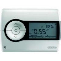
GW21853 - Thermostat Gewiss - Free user manual and instructions
Find the device manual for free GW21853 Gewiss in PDF.
| Product type | Electronic thermostat for fan-coil |
| Brand | Gewiss |
| Model | GW21853 |
| Dimensions (approx.) | 80 x 80 x 30 mm |
| Weight (approx.) | 150 g |
| Power supply | 230 V~ 50/60 Hz |
| Disconnection type | 1 B / Electronic |
| Control outputs | Fan (3 speeds) and solenoid valve |
| Maximum total load | 5(2) A at 250 V~ |
| Temperature setting range | +5°C to +30°C (mechanically limitable) |
| Reading accuracy | ±1°C |
| Maximum temperature gradient | 1K / 15 min |
| Control type | Proportional band (amplitude 1°C) |
| Protection rating | IP30 |
| Insulation class | Class II |
| Operating temperature | 0°C to +50°C |
| Maximum wire cross-section at terminals | 2.5 mm² |
| Main functions | Fan control (3 speeds) and solenoid valve, heating/cooling modes, fixed or thermostatic ventilation |
| Maintenance and cleaning | Clean with a dry cloth; do not use aggressive products |
| Safety | Installation by a professional; cut off power before intervention; respect polarity |
| Spare parts and repairability | Contact GEWISS customer service for any repair or part |
| General information | Electronic thermostat for fan-coil, compliant with CE standards (EMC and LVD) |
Frequently Asked Questions - GW21853 Gewiss
User questions about GW21853 Gewiss
0 question about this device. Answer the ones you know or ask your own.
Ask a new question about this device
Download the instructions for your Thermostat in PDF format for free! Find your manual GW21853 - Gewiss and take your electronic device back in hand. On this page are published all the documents necessary for the use of your device. GW21853 by Gewiss.
USER MANUAL GW21853 Gewiss
TERMOSTATO ELETTRONICO PER FAN-COIL
ELECTRONIC THERMOSTAT FOR FAN-COIL THERMOSTAT ÉLECTRONIQUE POUR FAN-COIL TERMOSTATO ELECTRÓNICO PARA FAN-COIL ELEKTRONISCHER THERMOSTAT FÜR FAN-COIL
CE
GW 20 853 - GW 21 853

natural_image
Pure electrical circuit lines without any symbols
flowchart
graph TD
    A["Fan-coil Fan-coil"] --> B["Flow Up"]
    A --> C["Flow Down"]
    D["Termostato Termostato"] --> E["Flow Up"]
    D --> F["Flow Down"]
    B --> G["Return to Ground"]
    C --> H["Return to Ground"]
    E --> I["Return to Ground"]
    F --> J["Return to Ground"]
Electronic thermostat for Fan-Coil
ATTENTION - IMPORTANT
- Congratulations for having choosing a Gewiss product. Gewiss products are constructed with careful attention to detail, using only high quality materials. Gewiss products assure you of peak performance over time.
- Carefully read the following instructions since they contain important information on installing and operating the product. The installer should give these instructions to the final user and ask him to read the contents.
- System programming products must be installed in conformity with the provisions of HD 384 - ÖEC364 regulations for devices for household or similar use in non-dusty rooms or where special protection against water penetration is not required.
- Ön case of failure and/or malfunction, contact an authorized technician or GEWÖSS SAT technical assistance service.
INÑÜX
page
• GÜNÜRAL PROÑUÉT ÑÜSÉRIPTION
- yunctions 14
• INSTALLATION INSTRUÉTIONS
-äocation advice 15
- electrical connections 16
• OPÜRATING INSTRUÉTIONS
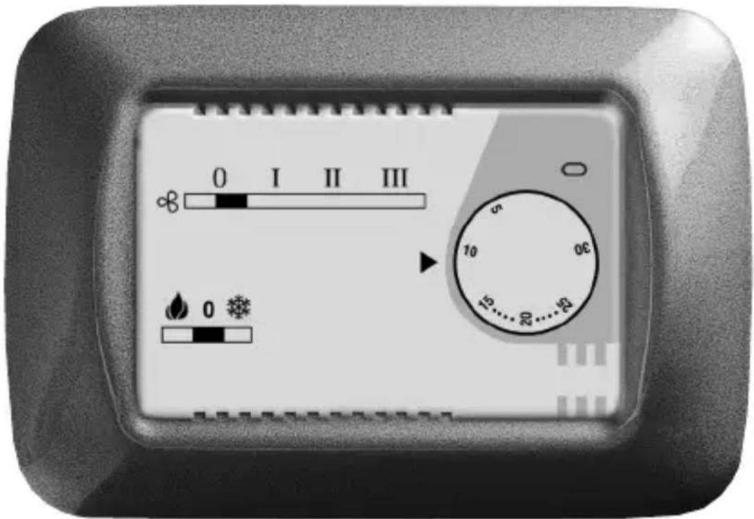
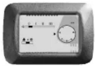
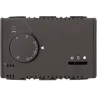
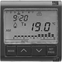
- Commands and signals 18
- èperating mode 19
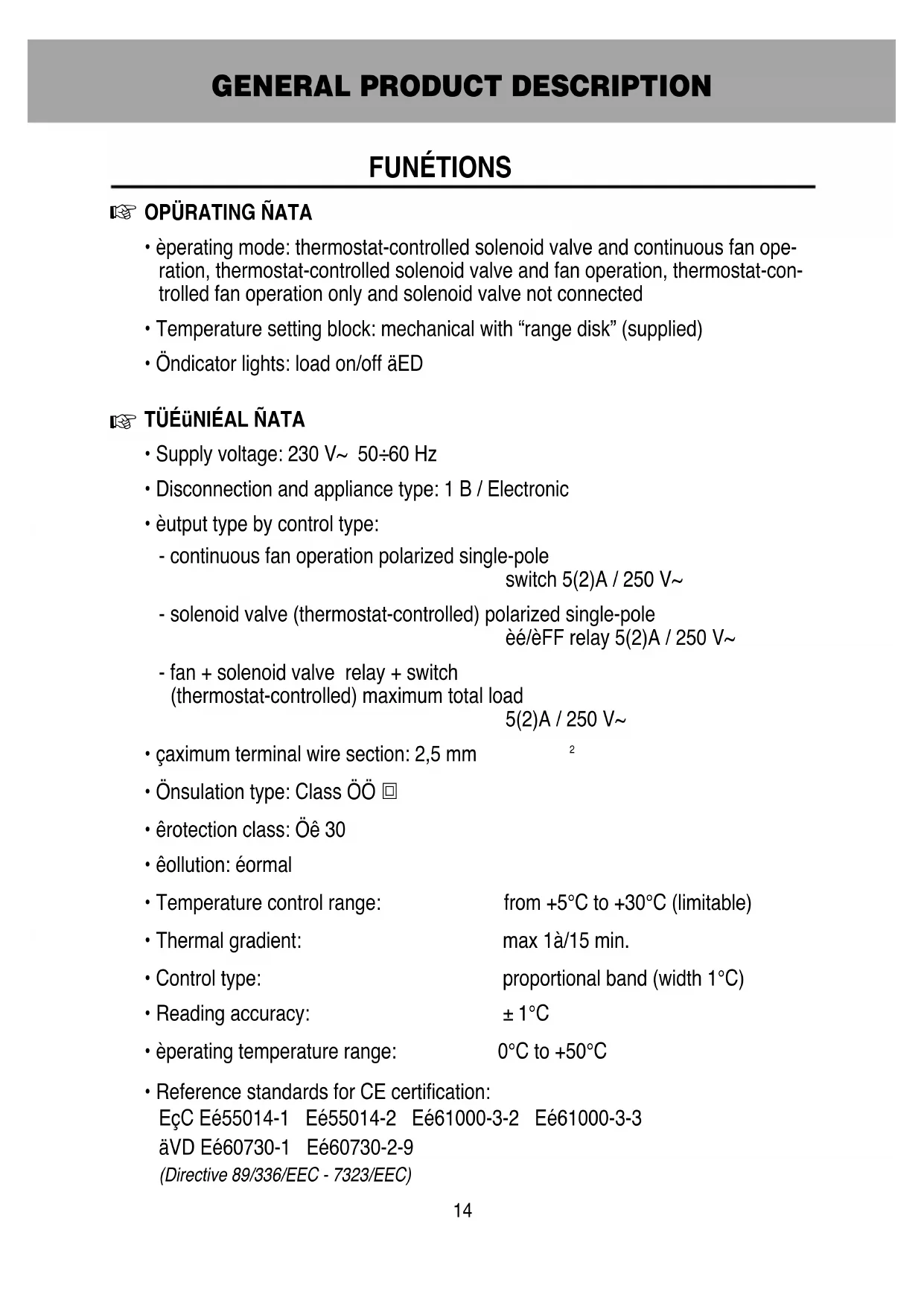
FUNÉTIONS

OPÜRATING ÑATA
- èperating mode: thermostat-controlled solenoid valve and continuous fan operation, thermostat-controlled solenoid valve and fan operation, thermostat-controlled fan operation only and solenoid valve not connected
- Temperature setting block: mechanical with "range disk" (supplied)
- Öndicator lights: load on/off äED

TÜÉÜNIÉAL ÑATA
• Supply voltage: 230 V\~ 50÷60 Hz
- Disconnection and appliance type: 1 B / Electronic
- èput type by control type:
- continuous fan operation polarized single-pole switch 5(2)A / 250 V\~
- solenoid valve (thermostat-controlled) polarized single-pole èé/èFF relay 5(2)A / 250 V\~
- fan + solenoid valve relay + switch (thermostat-controlled) maximum total load 5(2)A / 250 V\~
• çaximum terminal wire section: 2,5 mm
- Önsulation type: Class ÖÖ
- êrotection class: Öê 30
- éolution: éormal
• Temperature control range: from +5°C to +30°C (limitable)
• Thermal gradient: max 1 à/15 min.
• Control type: proportional band (width 1°C)
- Reading accuracy: ± 1^
- èperating temperature range: 0^ to +50^
• Reference standards for CE certification:
EçC Eé55014-1 Eé55014-2 Eé61000-3-2 Eé61000-3-3
äVD Eé60730-1 Eé60730-2-9
(Directive 89/336/EEC - 7323/EEC)
INSTALLATION INSTRUCTIONS
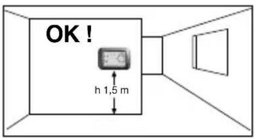
LOCATION ADVICE
OK


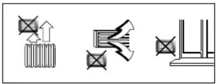
Recommendations on positioning:
Önstall the thermostat at a height of from 1.50 to 1.70 m from the floor, far away from sources of heat, air ducts, doors or windows.
natural_image
Pure electrical circuit lines without any symbols
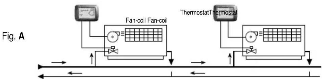
Example of installation with thermostat controlling the fan and solenoid valve.
ThermostatThermostat
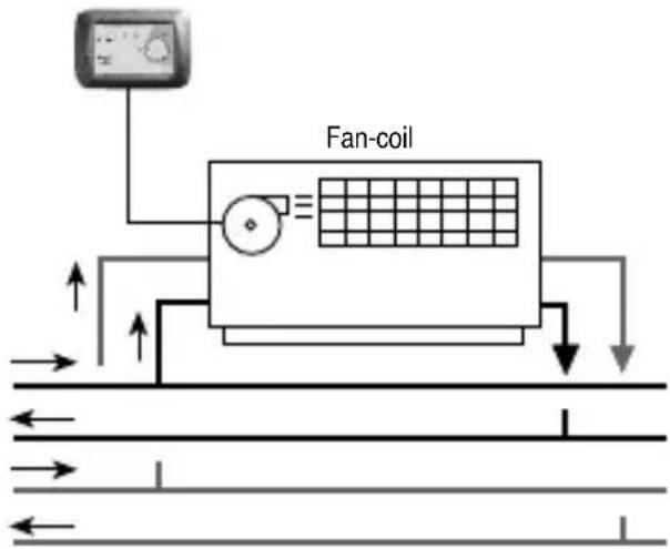
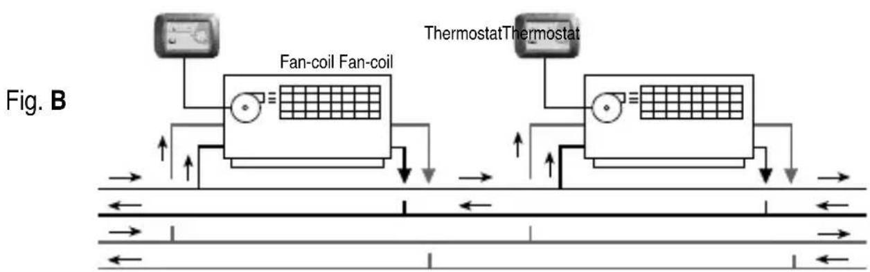
Example of installation with thermostat controlling only the fan.
N.B.: The examples shown in the following documentation are for illustration purposes only.
ELECTRICAL CONNECTIONS
Important: electrical wiring installation of the devices and appliances should be carried out by qualified technicians in accordance with the regulations and laws in force. The manufacturer will not assume any responsibility for the use of products that must comply with special environmental and/or installation regulations; this obligation is the responsibility of and to the charge of the installer.
Warning: before installing the product, disconnect the power supply.
Important: the thermostat control outputs are polarized; pay close attention to äine and éneutral connections.
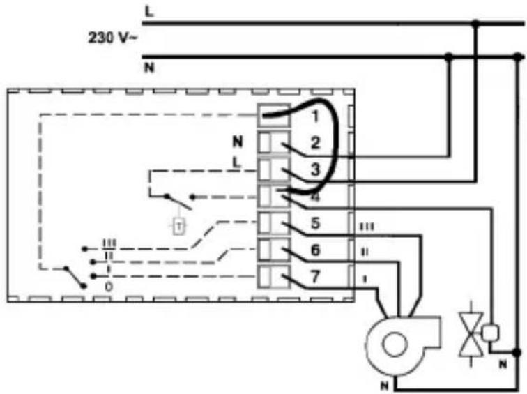
Wiring: as indicated in the figure.
Disconnect the power supply (main breaker).
Connect the fluid interception solenoid valve to terminal n° 4.
Based on the type of installation, connect the wires for speed control coming from the fan to terminals n° 5-6-7: terminal n° 5 - fan "High"
terminal n° 6 - fan "çedium"
ELECTRICAL CONNECTIONS
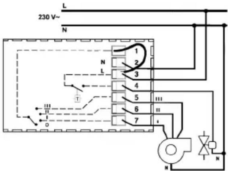
The setting wire must always be connected to terminal n° 3 or terminal n° 4.
Setting the Fan-coil control mode
N.B.: the solenoid valve is always thermostat controlled.
a) - Thermostat-controlled fan operation
Connect the wire that comes out of the first hole of the thermostat terminal board (hole 1) to terminal n° 4.
Wiring diagram for solenoid valve control and fan control with thermostat-controlled operation
b) - Continuous fan operation
Connect the wire that comes out of the first hole of the thermostat terminal board (hole 1) to terminal n° 3.
Wiring diagram for solenoid valve control and fan control with continuous fan operation
ÉOMMANÑS ANÑ SIGNALS
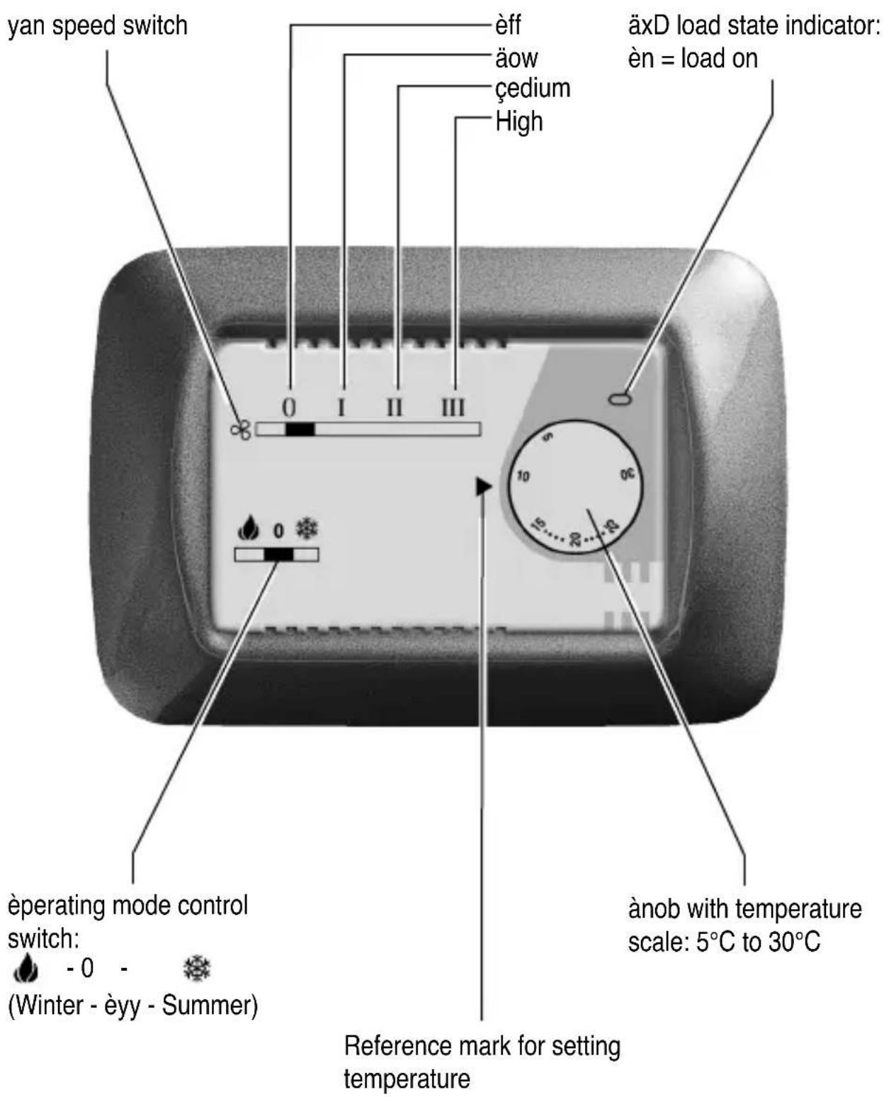
OPERATING PMODE
Based on the devices connected (fan and/or solenoid valve) and the terminal (n° 3 or n° 4) to which the wire for the fan operating mode setting is connected, the thermostat can operate in the following modes:
1) thermostat-controlled solenoid valve and continuous fan operation (fig. A)
2) thermostat-controlled solenoid valve and fan operation (fig. A)
3) thermostat-controlled fan operation only and solenoid valve not connected (fig. B)
Ön all cases, 3 different fan speeds can be selected by a switch on the front panel. Heating or cooling mode can also be selected by a switch on the front panel.
flowchart
graph LR
    A["Fan-coil Fan-coil"] --> B["Thermostat"]
    C["Thermostat"] --> D["Thermostat"]
    style A fill:#f9f,stroke:#333
    style C fill:#f9f,stroke:#333
    style B fill:#ccf,stroke:#333
    style D fill:#ccf,stroke:#333
Example of thermostat installation with thermostat-controlled solenoid valve and fan control (continuous or thermostat-controlled)
flowchart
graph TD
    A["Fan-coil Fan-coil"] --> B["Thermostat"]
    C["Thermostat"] --> D["Thermostat"]
    style A fill:#f9f,stroke:#333
    style C fill:#f9f,stroke:#333
    style B fill:#ccf,stroke:#333
    style D fill:#ccf,stroke:#333
Example of thermostat installation with fan control only (continuous or thermostat-controlled)
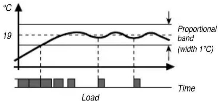
The thermostat operates with proportional temperature control, within a 1°C-band
width, as shown in the figure. Regulation is carried out by switching the load on and off for variable time intervals, depending on the difference between the temperature setpoint and the temperature reading.
line
| Time | Temperature (°C) | |------|------------------| | 0 | 18 | | 1 | 19 | | 2 | 19 | | 3 | 19 | | 4 | 19 | | 5 | 19 | | 6 | 19 | | 7 | 19 | | 8 | 19 | | 9 | 19 | | 10 | 19 | | 11 | 19 | | 12 | 19 | | 13 | 19 | | 14 | 19 | | 15 | 19 | | 16 | 19 | | 17 | 19 | | 18 | 19 | | 19 | 19 | | 20 | 19 |GEWISS
FRANÇAIS
LOGIQUE PD'APPLICATION
OK

natural_image
Pure electrical circuit lines without any symbols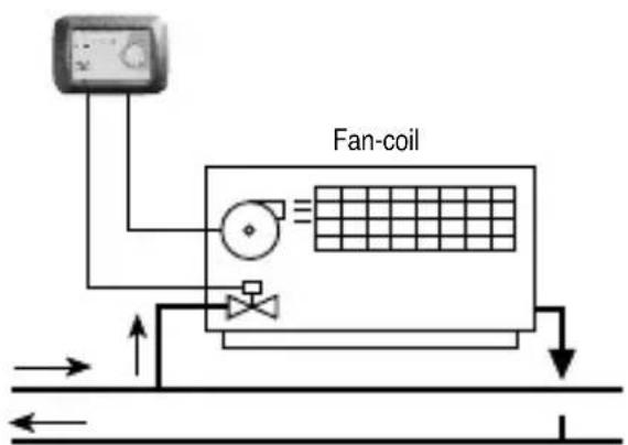
natural_image
Pure electrical circuit lines without any symbols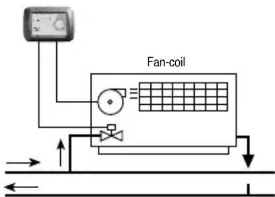
flowchart
graph TD
    A["Fan-coil Fan-coil"] --> B["Flow Up"]
    A --> C["Flow Down"]
    D["Termostato Termostato"] --> E["Flow Up"]
    D --> F["Flow Down"]
    B --> G["Return to Ground"]
    C --> H["Return to Ground"]
    E --> I["Return to Ground"]
    F --> J["Return to Ground"]

natural_image
Pure electrical circuit lines without any symbols
flowchart
graph TD
    A["Thermostat"] --> B["Fan-coil"]
    B --> C["Grid Flow Left"]
    B --> D["Grid Flow Right"]
    E["Thermostat"] --> F["Fan-coil"]
    F --> G["Grid Flow Left"]
    F --> H["Grid Flow Right"]
    I["Thermostat"] --> J["Fan-coil"]
    J --> K["Grid Flow Left"]
    J --> L["Grid Flow Right"]
    M["Thermostat"] --> N["Fan-coil"]
    N --> O["Grid Flow Left"]
    N --> P["Grid Flow Right"]
    Q["Thermostat"] --> R["Fan-coil"]
    R --> S["Grid Flow Left"]
    R --> T["Grid Flow Right"]
    U["Thermostat"] --> V["Fan-coil"]
    V --> W["Grid Flow Left"]
    V --> X["Grid Flow Right"]
    Y["Thermostat"] --> Z["Fan-coil"]
    Z --> AA["Grid Flow Left"]
    Z --> AB["Grid Flow Right"]
Date of installation
Room in which installed
äocal de l'installation
Installer's stamp and signature


- TERMOSTATO ELETTRONICO PER FAN-COIL
- ATTENTION - IMPORTANT
- INÑÜX
- • GÜNÜRAL PROÑUÉT ÑÜSÉRIPTION
- • INSTALLATION INSTRUÉTIONS
- • OPÜRATING INSTRUÉTIONS
- FUNÉTIONS
- OPÜRATING ÑATA
- TÜÉÜNIÉAL ÑATA
- INSTALLATION INSTRUCTIONS
- LOCATION ADVICE
- Recommendations on positioning:
- ELECTRICAL CONNECTIONS
- Setting the Fan-coil control mode
- a) - Thermostat-controlled fan operation
- b) - Continuous fan operation
- ÉOMMANÑS ANÑ SIGNALS
- OPERATING PMODE
- GEWISS
- FRANÇAIS
- LOGIQUE PD'APPLICATION
Brand : Gewiss
Model : GW21853
Category : Thermostat