GW14761 - Thermostat Gewiss - Free user manual and instructions
Find the device manual for free GW14761 Gewiss in PDF.

| Product Type | Wall chronothermostat for KNX/EIB system |
| Brand | Gewiss |
| Model | GW14761 |
| Use | Automatic ambient temperature management on a weekly basis |
| Main power supply | KNX/EIB bus (5 mA) |
| Backup power supply | 2 AAA 1.5 V batteries (to preserve date/time) |
| Display | Timed backlit LCD screen |
| Control buttons | 10 buttons (3 always accessible, 7 under flap) |
| Operating modes | Automatic, Economy, Pre-comfort, Comfort, Off (antifreeze / high temperature protection) |
| Operating types | Heating and air conditioning |
| Setpoint temperatures (heating) | Eco Temp (16 °C default), Pre-comfort Temp (18 °C), Comfort Temp (20 °C), Antifreeze Temp (5 °C) |
| Setpoint temperatures (air conditioning) | Comfort Temp (24 °C default), Pre-comfort Temp (26 °C), Eco Temp (28 °C), High temperature protection Temp (35 °C) |
| Control logic | 2-point (On/Off) or proportional (PWM) |
| Scheduling | Customizable per day of the week, 15-minute steps |
| Special functions | Party, Holiday, self-learning, holiday copy |
| Temperature sensor | Built-in NTC, measures every minute |
| Temperature display range | 0 to +45 °C |
| Protection rating | IP20 |
| Compliance | Low Voltage Directive 2006/95/EC, Electromagnetic Compatibility 89/336/EEC |
| Cleaning | With a dry cloth only |
| Installation | By qualified personnel, on wall mounting base or 3-module box |
Frequently Asked Questions - GW14761 Gewiss
User questions about GW14761 Gewiss
0 question about this device. Answer the ones you know or ask your own.
Ask a new question about this device
Download the instructions for your Thermostat in PDF format for free! Find your manual GW14761 - Gewiss and take your electronic device back in hand. On this page are published all the documents necessary for the use of your device. GW14761 by Gewiss.
USER MANUAL GW14761 Gewiss
Chronothermostat Easy - mural
Cronotermostato Easy - de pared
Dimensione (B x H x P)
130 × 92 × 23 ~mm
Position of controls 40
Control description 41
Operation mode 42
USER INSTRUCTIONS
Selecting heating/air conditioning 44
Setting parameters 44
Customising the daily programme 53
Temporary temperature override 54
Party Function 55
Holiday Function 56
Copying the holiday programme function 57
Low Battery indicator 58
Reset and reinstatement of default settings 58
Preset programs 59
Preset parameters 60
Behaviour on the failure and reinstatement of the bus power supply 60
Replacing the batteries 61
Cleaning the timer-thermostat 62
INSTALLATION INSTRUCTIONS
Correct installation position 63
Assembly of the support base 63
Warnings for KNX/EIB installations 64
Electrical connections 65
Initialization with the Easy base unit 66
Completing installation 67
Programming with the Easy base unit 67
TECHNICAL DATA 70
GENERAL INFORMATION
Warning! The safety of this appliance is only guaranteed if all the instructions given here are followed scrupulously. These should be read thoroughly and kept in a safe place. The Chorus products must be installed in compliance with the requisites of standard CEI 64-8 for devices for domestic use and similar, in non-dusty atmospheres and where special protection against water penetration is not required.
The GEWISS sales organisation is at your disposal for clarifications and technical information.
Gewiss SpA reserves the right to make changes to the product described in this manual at any time and without giving any notice.
Pack content
n. 1 Easy wall timer-thermostat
n. 1 Support base
n. 1 Bus terminal
n. 1 Installation and user manual
Summary
Easy wall Timer-Thermostat allows you to automatically manage the temperature in the area it is installed in on a weekly basis. The temperature is regulated by the KNX/EIB actuators which are managed by the Home Automation KNX/EIB bus and control the heating or air-conditioning systems. When combined with the Easy wall Timer-Thermostats (GW10 763 - GW14 763), from which it receives the function type and mode via the bus, it is possible to create multi-zone thermal regulation systems.
The temperature profiles are defined on a weekly basis. It is possible to programme an independent time profile for each day of the week, with a 15 minute resolution and without limits to the daily variations. The timer-thermostat comprises:
- 2 function types: heating and air conditioning;
- 5 function modes: OFF, Economy, Precomfort, Comfort and Automatic;
- 4 temperature settings for the heating function (ECONOMY, TPRECOMFORT, TCOMFORT, TFROSTPROTECT);
- 4 temperature settings for the air conditioning function (TECONOMY, TPRECOMFORT, TCOMFORT, THIGH TEMPERATURE PROTECTION),
- 2 control algorithm which can be set locally: with 2 points (ON/OFF command) and PI (PWM type control).
The timer-thermostat is powered by the supplied bus line and is fitted with a timed backlit LCD display, 10 control buttons, an integrated sensor to detect the ambient temperature (the value of which is sent to the bus every 15 minutes), alkaline batteries (AAA) to maintain the date and time on the display should the power be disconnected from the bus.
The output channels can be configured to:
- send the ON/OFF command to the KNX/EIB actuators that control the thermal regulation system (max 2 for heating / air-conditioning);
- set the function type (heating/air-conditioning) and function mode (OFF/Economy/Preconformt/Comfort) for the zone thermostats;
- transmit the settings (function type and mode) and the current data (read temperature) to other devices, for instance the EASY GSM repeater - GW 90 861.
The input channels can be configured to:
- remotely control the timer-thermostat function type and mode with other KNX/EIB devices (for instance the Easy GSM remote control unit - GW 90 861);
- manage scenes, associating a function type or mode to a specific scene;
- manage an incoming signal, for instance a contact when a window is opened, to temporarily switch off the timer-thermostat.
The device is installed on the wall using the supplied flange that can be fixed to the wall using dowels or screwed onto a 3 module flush-mount box.
GENERAL DESCRIPTION
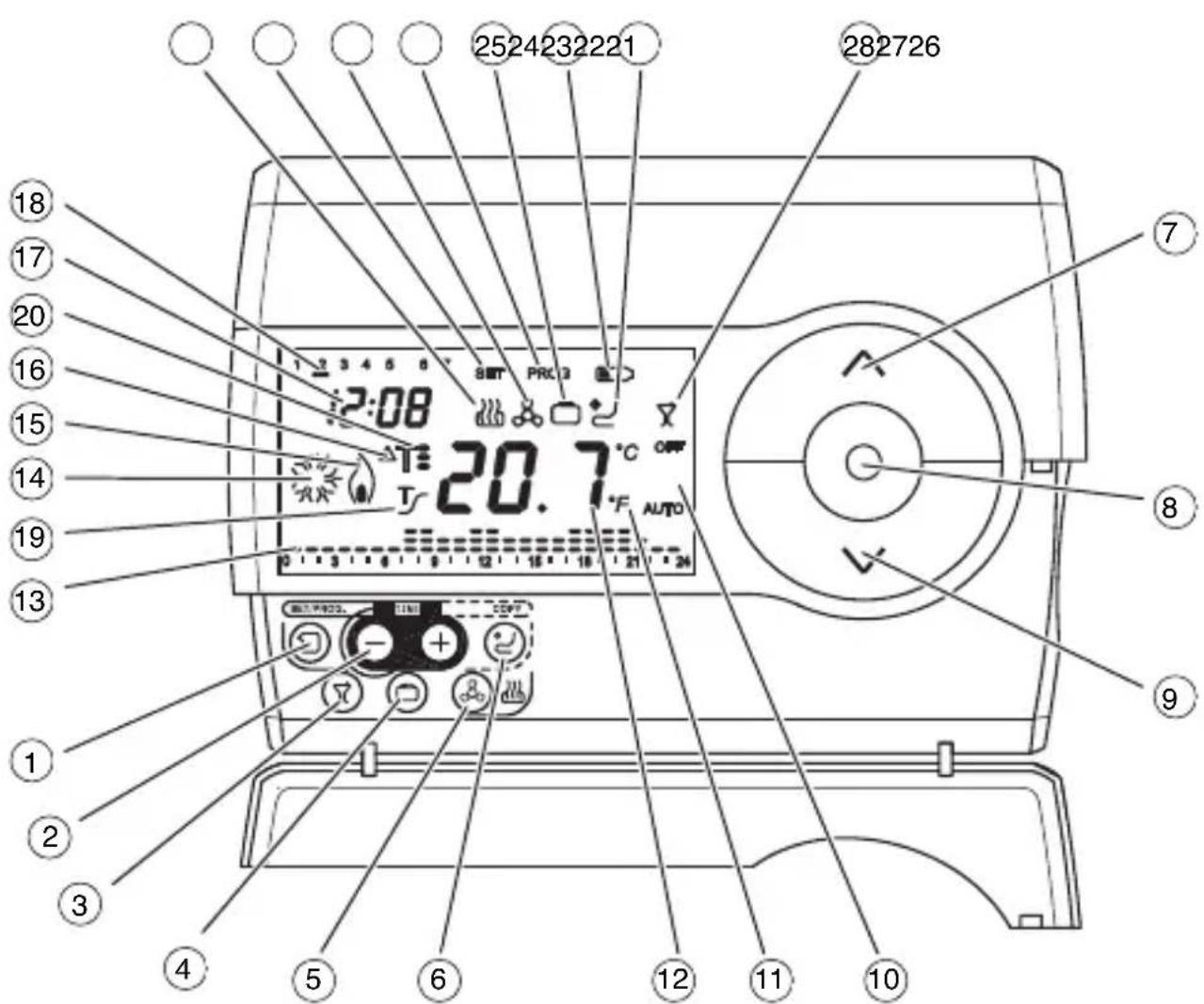
Position of the controls
The timer-thermostat is fitted with a display, 3 control buttons which are always accessible and 7 control buttons which can be accessed when the cover is open.
GENERAL DESCRIPTION
Control description
CONTROL BUTTONS Symbol Page
1 Programming / setting
2 Regulating the time
③ Party 55
④ Holiday 56
5 Selecting heating/air conditioning 44
6 Copy 57
⑦ Temperature regulation (+) / select parameters
8 Select function mode / confirmation
9 Temperature regulation (-) / select parameters
⑥
⑦
品
A
VDU SIGNALS
10 Function Mode 42
11 Temperature unit of measurement 46
12 Ambient temperature measured
13 Daily program profile 53
14 Activation of air-conditioning 43
15 Activation of heating 43
Thermal differential 49
17Clock 46
Day of the week 46
19 Activation of self-learning function 52
20 Temperature set-point - function mode
Heating function
22 Parameter setting status
23 Air conditioning function
24 Programming status
25 Holiday Function
26 Low Batteries
27 Copy holiday programme function
28 Party Function
AUTO
^ C / ^


T
T. T: T 47
43
SET 46
43
PROG 53
56
58
57
X 55
GENERAL DESCRIPTION
Operation mode
The timer-thermostat provides 5 different operation modes:
AUTOMATIC
ECONOMY
PRECOMFORT
COMFORT
- OFF-FROSTPROTECT/HIGH TEMPERATURE PROTECTION
Use the key to switch from one mode to another.
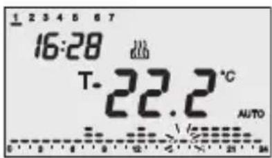
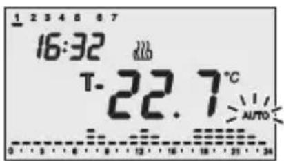
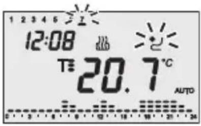
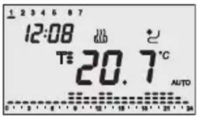
When in automatic mode the timer-thermostat uses a programme that can be customised for each day of the week.
The message "AUTO", the measured ambient temperature and the set point symbol relative to the current quarter-hour are displayed on the screen.
The column relative to the current time with the representation of the active set point blinks in the time profile.
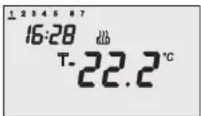
In the economy, precomfort and comfort function modes the timer-thermostat permanently uses the corresponding temperature set-points.
The current ambient temperature and the symbolT, T= o appear on the screen.
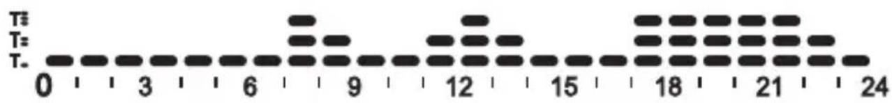
MEANINGS OF T. T: T
| Symbol | Heating Air conditioning | |||
| Set point | Operating mode | Set point | Operating mode | |
| Tc | TECONOMY Economy | TCOMFORT | Comfort | |
| Tε | TPRECOMFORT | Precomfort | TPRECOMFORT | Precomfort |
| Tε | TCOMFORT | Comfort | TECONOMY | Economy |
GENERAL DESCRIPTION
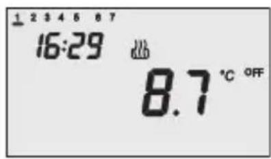
The frostprotect function is only enabled in heating function mode, when the thermal regulation system is OFF. In this case the timer-thermostat uses the set frostprotect temperature set-point, re-starting the heating system only when the ambient temperature decreases below TFOSTPROTECT.
The message "OFF" and the measured ambient temperature are displayed on the screen.
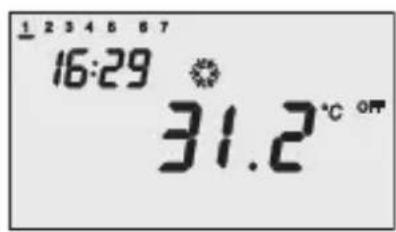
The high-temperature protection function is only enabled in air-conditioning mode, when the thermal regulation system is OFF.
In this case the timer-thermostat uses the set high-temperature set-point, re-starting the air-conditioning system only when the ambient temperature exceeds the HIGH TEMPERATURE PROTECTION.
The message "OFF" and the measured ambient temperature are displayed on the screen.
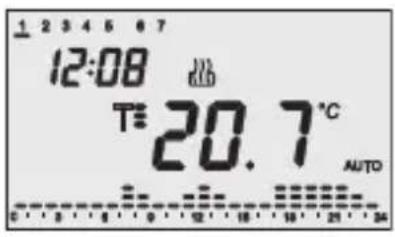
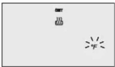
The activation of the heating or air-conditioning functions are indicated as followed:
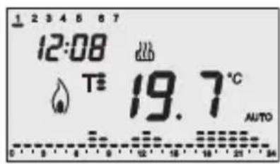
Heating
The symbol indicates that the activation command has been sent to the actuator which controls the boiler. If the timer-thermostat does not receive confirmation from the actuator that the same has been activated, the symbol starts to flash. Subsequently, the timer-thermostat sends the activation command again, at one minute intervals, until it receives a positive response.
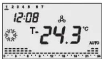
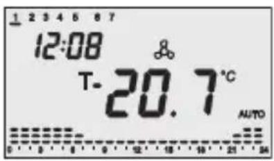
Air conditioning
The symbol indicates that the activation command has been sent to the actuator which controls the air-conditioner. If the timer-thermostat does not receive confirmation from the actuator that the same has been activated, the symbol starts to flash. Subsequently, the timer-thermostat sends the activation command again, at one minute intervals, until it receives a positive response.
USERINSTRUCTIONS
Selecting heating/air conditioning
Press the key to switch the function modes from heating to air-conditioning and vice-versa.
Heating
The symbol indicates the heating mode.
Air conditioning
The symbol indicates the air-conditioning mode.
Setting parameters
To set the timer-thermostat parameters:
- use the to select the function type (heating/air conditioning);
- press the key once
The word SET and the clock appears on the screen, and the day of the week cursor starts to flash.
USERINSTRUCTIONS
According to the function type, it is now possible to sequentially modify:
| Day of the week | |
| Hour | |
| Minutes | |
| Temperature unit of measurement | |
| Heating Air conditioning | |
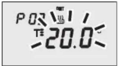
| P01heat - Set Point P01 | cond - Set Point T. |
| P02heat - Set Point P02 | cond - Set Point T: |
| P03heat - Set Point P03 | cond - Set Point T: |
| P04heat - Set Point TFROSTPROTECT P04 | cond - Set Point THIGH TEMPERATURE PROTECTION |
| P05heat - ON/OFF heating regulation differential value | P05cond - ON/OFF air conditioning regulation differential value |
| P06heat - Control logic P06 | cond - Control logic |
| P07heat - Cycle time P07 | cond - Cycle time |
| P08heat - PWM regulation differential value | P08 cond - PWM regulation differential value |
| P09heat - Activation of self-learning function | |
To scroll the sequence, confirming the values displayed on the screen, press the key until you reach the parameter you want to change. Press the key again to exit the parameter setting procedure or it will exit automatically after a 30" time-out.
It is necessary to perform both sequences to set the heating and air-conditioning parameters (in the second sequence it is possible to confirm the parameters which are the same, and just change the specific ones).
USERINSTRUCTIONS
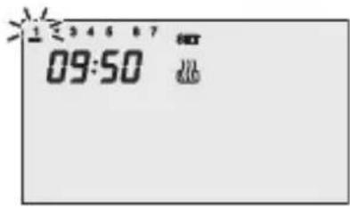
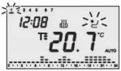
Setting the day of the week
When the day of week bar is blinking, select the current day using the keys+
(Monday=1, Tuesday=2, Sunday=7).
Press the key within 30 seconds to confirm the value set.
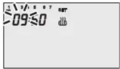
Setting the hour
When the hour figures blink, set the time using the keys+
Press the key within 30 seconds to confirm the value set.
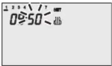
Setting the minutes
When the minutes figures blink, set the minutes using the keys+
Press the key within 30 seconds to confirm the value set.
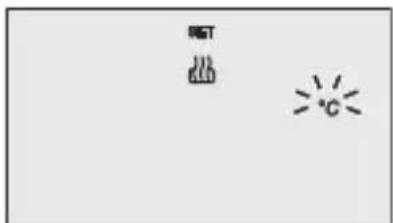
Setting the temperature unit of measurement
When the temperature symbols ^ C or ^ starts to blink, select the temperature unit of measurement using the keys.
Press the key within 30 seconds to confirm the value set.
USERINSTRUCTIONS
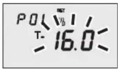
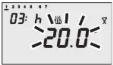
P01heat - Set Point setting (heating)
The temperature value starts to blink when the Tsymbol appears. Regulate the value (TECONOMY) using the keys.
Press the key within 30 seconds to confirm the value set.
P01 cond - Set Point setting (air conditioning)
The temperature value starts to blink when the T. symbol appears. Regulate the value (T COMFORT) using the keys.
Press the key within 30 seconds to confirm the value set.
P02risc - Set Point setting (heating)
The temperature value starts to blink when the Tz symbol appears. Regulate the Value (T PRECOMFORT) using the Keys.
Press the key within 30 seconds to confirm the value set.
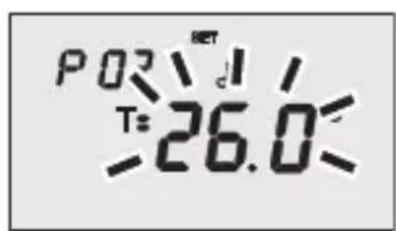
P02cond - Set Point setting (air conditioning)
The temperature value starts to blink when the T symbol appears. Regulate the value (TPRECOMFORT) using the keys.
Press the key within 30 seconds to confirm the value set.
USERINSTRUCTIONS
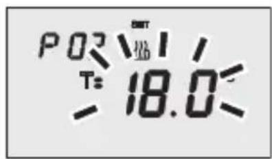
P03heat - Set Point setting (heating)
The temperature value starts to blink when the T3 symbol appears. Regulate the value (T COMFORT) using the Keys.
Press the key within 30 seconds to confirm the value set.
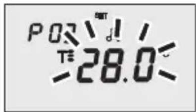
P03cond - Set Point Setting (air conditioning)
The temperature value starts to blink when the T symbol appears. Regulate the value (T ECONOMY) using the Keys.
Press the key within 30 seconds to confirm the value set.
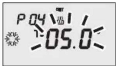
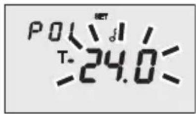
P04heat - set frostprotect temperature value
The temperature value starts to blink when the symbol appears. Regulate the temperature frostprotect value using the Keys.
Press the key within 30 seconds to confirm the value set.
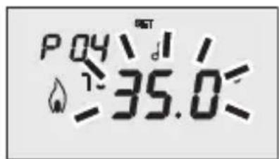
P04cond - Set high temperature protection value
The temperature value starts to blink when the symbol appears. Regulate the high temperature protection value using the keys.
Press the key within 30 seconds to confirm the value set.
WARNING!
The set-point values have the following limits:
- Heating
T FROSTPROTECT
T. T:
T
Air conditioning

THIGH TEMPERATURES PROTECTION
USERINSTRUCTIONS
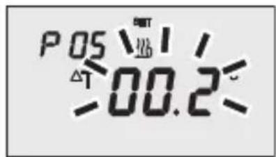
P05 - setting the ON/OFF regulation differential
When the T , symbol appears, set the differential regulation value using the keys.
Press the key within 30 seconds to confirm the value set.
The regulation differential is the deviance between the set-point setting and the actual activation temperature. It is possible to set different regulation differentials for the heating and air-conditioning functions. It is recommended to retain the preset values except in special situations.
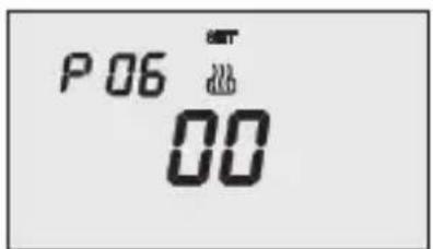
P06 - Control logic
When the P06 code appears on the screen, set the thermal regulation control logic using the keys. (00 = 2 point control, 01 = proportional control (PWM))
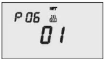
Press the key within 30 seconds to confirm the value set.
It is possible to set different control logics for the heating and air-conditioning functions.
If you select a 2 point control, move on to point P09, for proportional control move on to point P07.
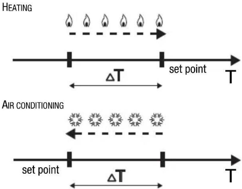
2 POINT CONTROL
The thermal regulation plant is disabled when: the temperature is equal to the set point and reactivated when:
- the temperature is equal to or lower than the set point
- for heating;
- the temperature is equal to or higher than the set point + for air-conditioning;
The diagrams below show the two function types.
USERINSTRUCTIONS
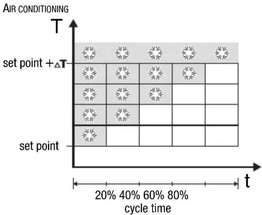
PROPORTIONAL CONTROL (PWM)
The proportional channel (from set point to set point - for heating, from set point to set point + for air conditioning) is divided into four equal zones.
At the end of each cycle time, the timer-thermostat controls the ambient temperature and, according to the differences recorded, it modulates the proportion of the ON and OFF commands transmitted during the cycle time.
The diagrams below show the behaviour of the proportional control in heating and air-conditioning functions.
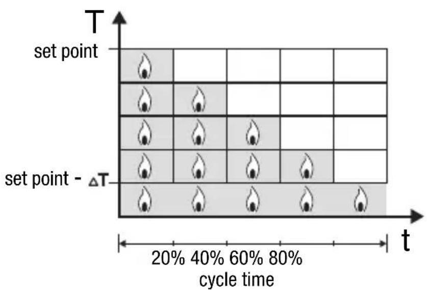
HEATING
USERINSTRUCTIONS
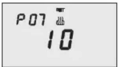
P07 - setting the cycle time
When the P07 code appears on the screen, set the cycle time using the keys.
The values available are as follows: 5, 10, 20, 30, 40, 50, 60 minutes.
It is possible to set different cycle times for the heating and air-conditioning functions.
Press the key within 30 seconds to confirm the value set.
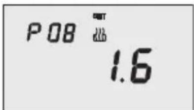
P08 - setting the PWM regulation differential value
When the P08 appears on the display, set the differential PWM regulation value using the Keys.
It is possible to set different PWM values for the heating and air-conditioning functions. Press the key within 30 seconds to confirm the value set.
The parameter setting procedure has now been completed. Press the key to return to normal operating mode.
USER INSTRUCTIONS
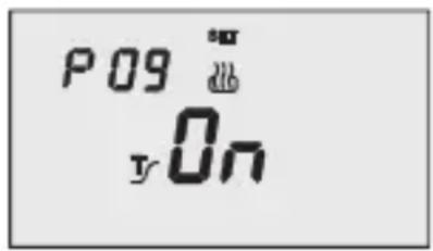
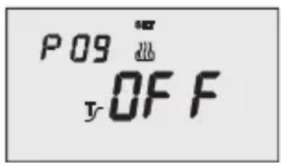
P09 - enabling self-learning (heating only)
When the symbol appears on the screen, use the keys to enable (ON) or disable (OFF) the function. Press the key within 30 seconds to confirm the value set.
The self-learning function optimises the activation of the heating in advance (max 2 hours).
The timer-thermostat manages the advance automatically, so as to guarantee the set temperature at the beginning of every period of the programmed profile. This function is activated in heating, in automatic operation mode only.
The parameter setting procedure has now been completed. Press the key to return to normal operation mode.
Customising the daily programme
To customise the preset daily programme, or modify the settings, press the key twice.

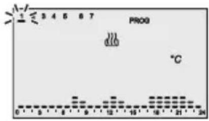
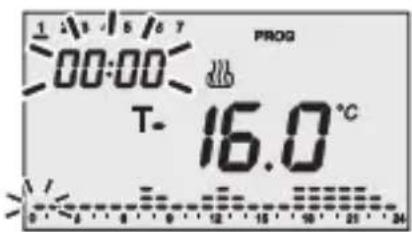
The message "PROG" is displayed on the VDU, while the bar of the first day of the week starts to blink.
Select the required day using the keys+
Press the key within 30 seconds to confirm the selection.
After confirmation of the day, the current profile, relative to the day selected, is displayed on the screen.
The time will start to blink.
Follow the steps below to customise the settings:
1 - select the starting time for the change in temperature
2 - set the new temperature set point
3 - completing the customisation process
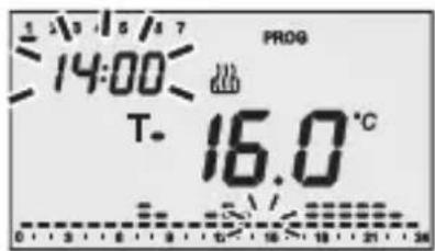
1 - Select the starting time for the change in temperature
Use the keys to change the time until you reach the profile you wish to change; the selected time column flashes as the hour profile increases. The time is decremented/incremented in steps of 15 minutes each time the keys are pressed, so it is possible to define up to 4 programming periods each hour.
USERINSTRUCTIONS
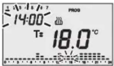
2 - Setting the new temperature set point
The current set point value is indicated on the display by the symbol Tor Tz Tz
The keys are then used to select the new set point, which will be applied to the time profile until the next variation present in the program.
3 - Completing the customisation process
After repeating steps 1 and 2 to reach the desired temperature hour profile, it is possible to:
- copy the programme to the next day and confirm the performed programming phase by pressing the key within 30 seconds, or
- confirm the performed programming without copying it, by pressing the key within 30 seconds (this moves the programming on to the next day automatically).
Press the key on completion of weekly programming to return to normal operating.
To activate the program, select AUTO operating mode by pressing the key until the message "AUTO" is displayed on the screen.
Temporary temperature override
It is possible to temporarily the active temperature set point in AUTO, Economy, Precomfort and Comfort operation modes by using the keys to set the required value. Confirm the new value by pressing the key or waiting for 5 seconds.
The word AUTO will flash on the display to indicate override is enabled or, in the other cases, when, or flashes.
The override of the AUTO mode remains active until the next variation in the temperature time profile.
Party Function
When in AUTO, Economy, Precomfort and Comfort mode the Party function allows you to temporarily exclude the set function mode and enable the comfort mode with an adjustable set point, for a period of time of from 1 - 23 hours.
This function can be used, for instance, to set a more comfortable temperature during a dinner or a party etc.
Press the key twice to enable the function.
The symbol appears on the screen, whilst the setT point value flashes.
Use the keys to set the desired temperature.
Press the keys to set the number of hours for which the Party function should be enabled, which is then indicated in the top left hand corner of the screen.
Press the key or wait 5 seconds to confirm the setting made.
When the function is enabled, it is possible to change the set point value pressing the keys and the activation period using the keys.
The count of the hours is decremented during operation.
The party function remains active until the set period elapses.
When the set time expires, the Party function is automatically disabled and the timer-thermostat returns to its regular function mode.
Press the key to disable the Party function before the expiry time.
USERINSTRUCTIONS
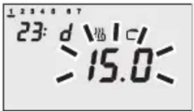
Holiday Function
When in AUTO, Economy, Precomfort and Comfort mode the Holiday function allows you to temporarily exclude the set function mode and enable the Economy mode with an adjustable set point, for a period of time of from 1 - 99 days.
This function can be used, for instance, to set the thermal regulation system so it runs economically during a holiday period, or during a prolonged period of absence, and adjusts the settings the day you return.
Press the key twice to enable the function.
The symbol appears on the screen, whilst the set point value flashes.
Use the keys to set the desired temperature.
Use the keys to set the number of days for which the Holiday function should be enabled, which is then indicated in the top left hand corner of the screen.
Press the key or wait 5 seconds to confirm the setting made.
When the function is enabled, it is possible to change the set point value pressing the keys and the activation period using the keys+
The count of the days is decremented during operation.
The Holiday function remains on until the set expiry date, which ends at midnight.
When calculating the number of days, always include the current day.
For instance, if you want to set the Holiday function on Friday evening so that it ends on Sunday at midnight, you should set 3 days (Friday, Saturday and Sunday).
When the set time expires, the Holiday function is automatically disabled and the timer-thermostat returns to its regular function mode.
Press the key to disable the Holiday function before the expiry time.
Copying the holiday programme function
In AUTO mode it is possible to copy the holiday profile (7) to any other day of the week. This function can be activated up to 6 days before the selected day.
This function is particularly useful when, for instance, there is a day's holiday during the week.
Press the key to copy the holiday profile.
The symbol and the holiday day cursor will flash on the display.
Use the keys to select the day of the week to which the holiday profile should be copied.
Press the key or wait 30 seconds to confirm the setting made.
When the function is enabled, press the key to view the day to which the holiday profile was copied; the corresponding cursor will flash on the display.
If you wish to disable the function, press the again; if you wish to change the day of the week, use the keys and press the key, or wait 30 seconds, to confirm the new settings.
During the day the symbol indicator light is always ON.
The validity of the holiday copy function is temporary; at midnight of the selected day the system returns to the normal weekly profile programme.
USER INSTRUCTIONS
Low Battery indicator
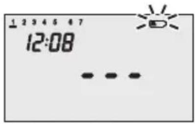
When the batteries are low and there is not bus power the symbol will start to flash on the screen.
The temperature indications also disappear from the screen and it is necessary to replace the batteries as soon as possible.
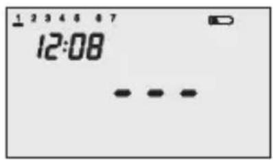
When the symbol is ON with a fixed light, it is essential to replace them immediately.
The batteries are only used to preserve the time and date settings when there is no bus KNX/EIB power (all the other settings are stored in the non-volatile memory).
When the bus power is present it will always function even without batteries.
Reset and reinstatement of default settings
Press the, and keys all together to completely reset the timer-thermostat.
Caution: all the previously set parameters and customised programmes will be cancelled.
When it is turned back on, the timer-thermostat will use the default factory settings. The timer-thermostat will be set to heating, in OFF mode and the Party and Holiday functions will not be enabled.
USERINSTRUCTIONS
Preset programs
The timer-thermostat has 2 preset programs, one for heating and one for air conditioning.
HEATING PROGRAM
Monday - Friday
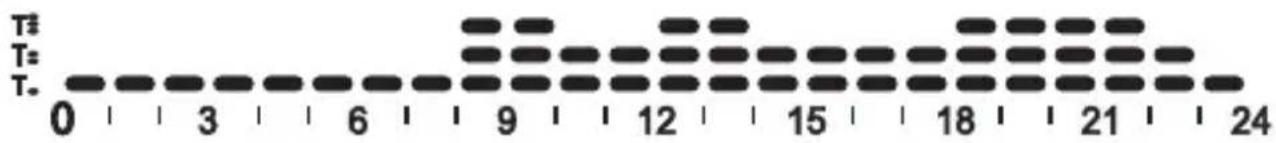
Saturday - Sunday
AIR CONDITIONING PROGRAM
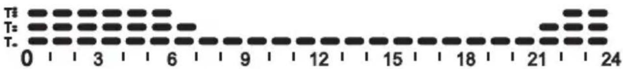
Every day of the week
These preset programs can be modified and personalised according to one's own requirements. To change the preset parameters, follow the instructions provided in the "Customising the daily programme" paragraph.
Preset parameters
| Day of the week | 1:Monday | |
| Hour | 00:00 | |
| Heating temperature set-point | T. | 16 °C |
| T: | 18 °C | |
| T3 | 20 °C | |
| TFROSTPROTECT | 5 °C | |
| Air-conditioning temperature set-point | T. | 24 °C |
| T: | 26 °C | |
| T3 | 28 °C | |
| THIGH TEMPERATURES PROTECTION | 35 °C | |
| Self-learning | OFF | |
| Differential regulation | Heating | 0.2 °C |
| Air conditioning | 0.5 °C | |
| Temperature unit of measurement | °C |
Behaviour on the failure and reinstatement of the bus power supply
When the bus power supply fails, the device performs no actions. The time and date are maintained by the buffer power system (batteries) whilst all the other settings are saved to a non-volatile memory.
The device is in full operating mode within a maximum of 5 seconds from reinstatement of the bus power supply
If the buffer power (battery) is absent, the timer-thermostat will restart in OFF mode when the bus power is reinstated.
USERINSTRUCTIONS
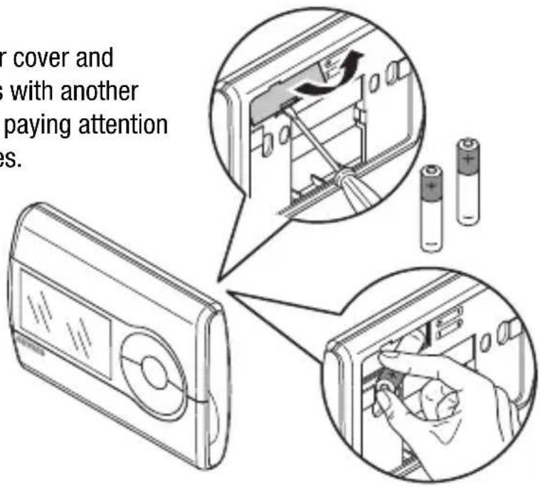
Replacing the batteries
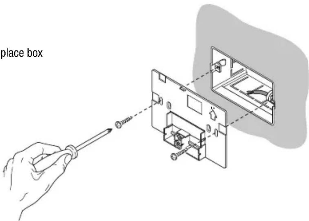
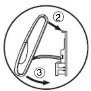
Remove the fastener screws which are under the front cover, and remove the timer-thermostat from the support base, as seen in the figure below.
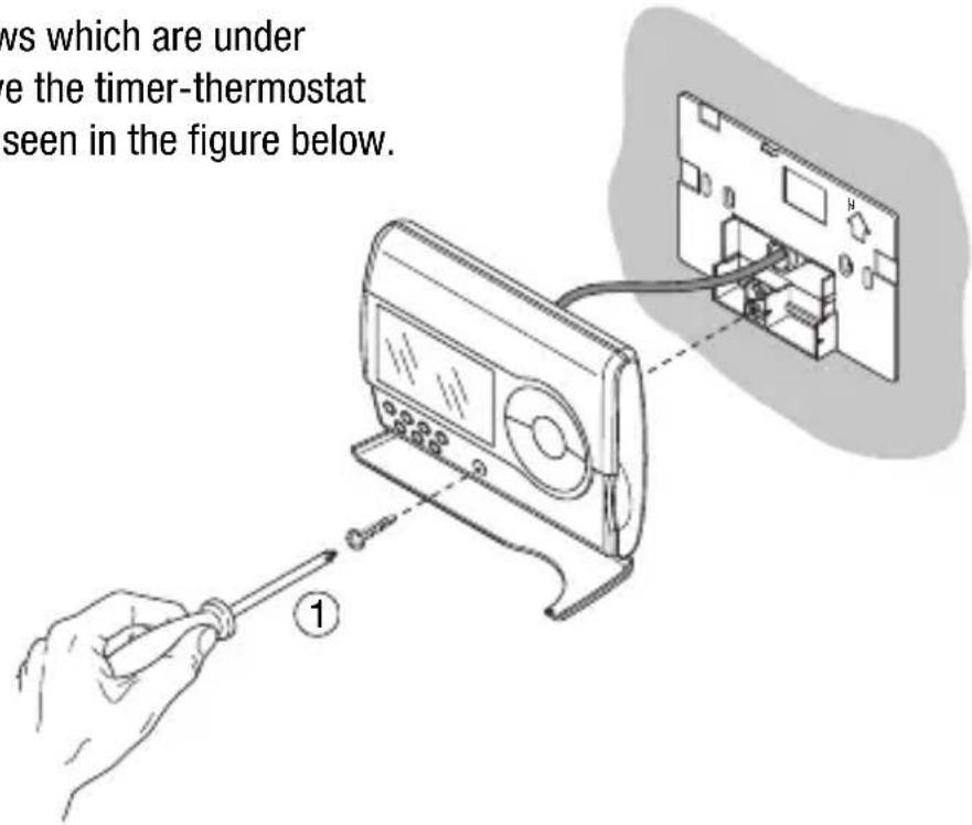
Remove the battery holder cover and replace the dead batteries with another two 1.5 V (AAA) batteries, paying attention to the direction of the poles.
USERINSTRUCTIONS
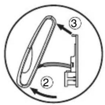
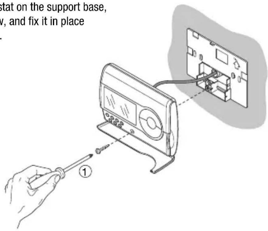
Replace the timer-thermostat on the support base, as seen in the figure below, and fix it in place using the supplied screws.
WARNING:

-
If the timer-thermostat was not powered by the bus whilst replacing the battery, update the time and date.
-
Replace all the batteries at the same time.
-
Never use old and new batteries together.
-
Always use the same type of batteries (do not mix alkaline and carbon zinc batteries).
-
Never throw the batteries into a fire.

- The batteries are a special waste product and therefore it must be disposed of according to the laws in force and taken to a special collection centre.
Cleaning the timer-thermostat
Use a dry cloth to clean the timer-thermostat.
INSTALLATION INSTRUCTIONS

WARNING: the installation of the device must be exclusively done by qualified personnel, following the regulations in force and the guidelines for KNX/EIB installations.
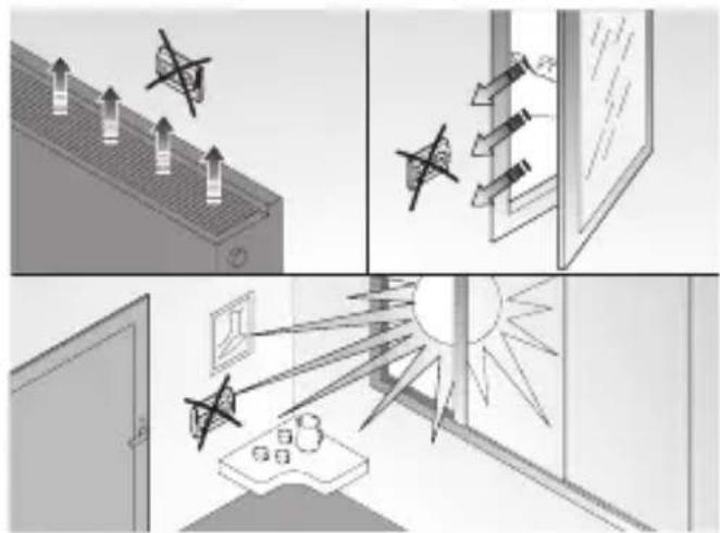
Correct installation position
In order for the timer-thermostat to take correct readings of the ambient temperature, it must not be installed in an alcove, near a door or window, next to radiators or air conditioner units and must not be placed in direct sunlight or in draughty areas.
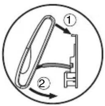
Assembly of the support base
The support base should be positioned at 160~cm from the ground and can be mounted on the wall, using dowels, or on top of a 3-place box.
WARNING: When mounting the support base, make sure you follow the directions indicated by the arrow.
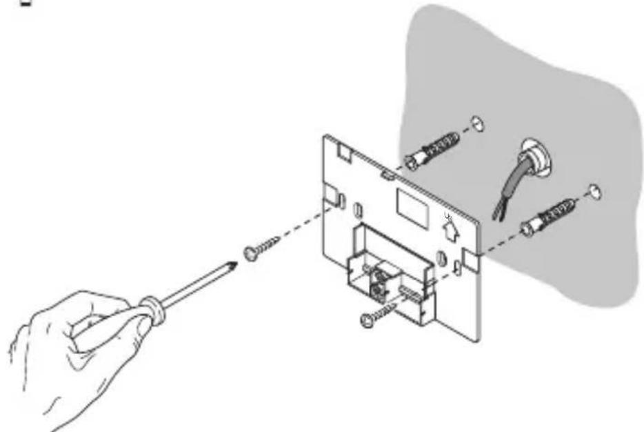
Mounting with dowels
INSTALLATION INSTRUCTIONS
Mounting on a 2-place box
Warnings for KNX/EIB installations
- The length of the bus line between the Easy timer-thermostat and the power supply unit must not exceed 350 metres.
- The length of the bus line between the Easy timer-thermostat and the most distant KNX/EIB device must not exceed 700 metres.
- If possible do not create ring circuits so as to prevent undesirable signals and overloads.
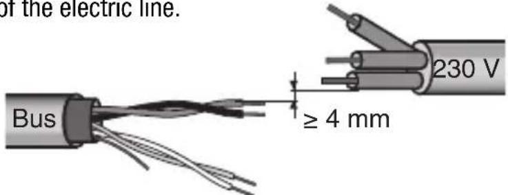
- Keep a distance of at least 4mm between the individually insulated cables of the bus line and those of the electric line.
- Do not damage the electrical continuity conductor of the shielding.

INSTALLATION INSTRUCTIONS

WARNING: the unused bus signal cables and the electrical continuity conductor must never touch elements under power or the earth conductor.
Electrical connections
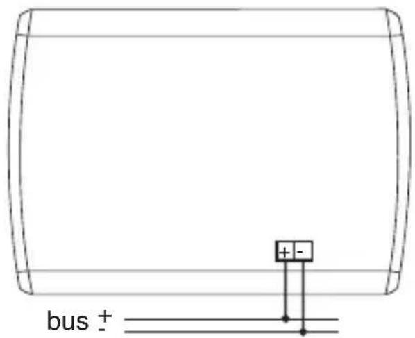
Electrical connections diagram
- Before connecting the KNX/EIB bus, insert the buffer memory batteries (see Replacing the Batteries paragraph).
- Connect the bus cable's red wire to the terminal's red connector (+) and the black wire to the black connector (-) . Up to 4 bus lines (wires of the same colour in the same connector) can be connected to the bus terminal.
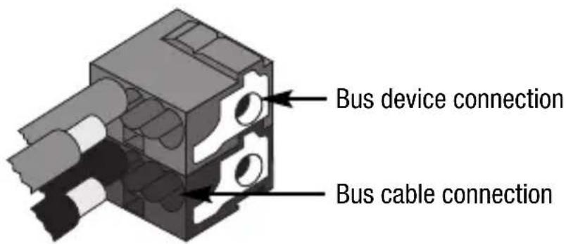
- Insulate the screen, the electrical continuity conductor and the remaining white and yellow wires of the bus cable (should a bus cable with 4 conductors be used), which are not needed.
INSTALLATION INSTRUCTIONS
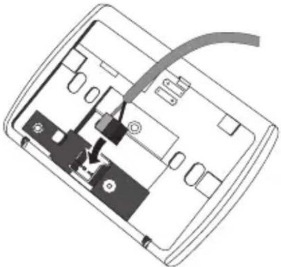
- Insert the bus connector into the special feet of the device. The fastener guides determine the direction it should be inserted.
Initialization with the Easy base unit
- Power up the device using the bus and wait for 5 seconds until it is in full operating mode
- Have the system acquire the device with one of the following procedures:
Automatic acquisition (the device still has the factory settings):
-
select the "Application New function" or "Application Edit function" menu in the Easy base unit: the device will be recognized automatically.
-
Manual acquisition (the factory settings have been modified):
-
select the "Application Search device" menu in the Easy base unit;
- briefly press (< 2 seconds) the programming key. The programming LED will light up during the acquisition process.
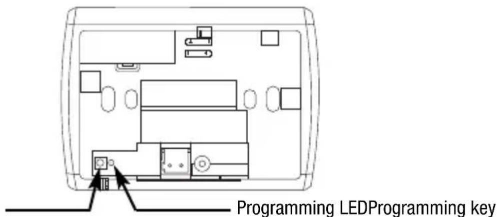
The device acquired by the Easy base unit will be listed, with the number assigned, in the channels of the "Application New function" or "Application Edit function" menus.
INSTALLATION INSTRUCTIONS
Completing installation
Position the timer-thermostat on the support base, as seen in the figure below, and fix it in place using the supplied screws.
Programming with the Easy base unit
Programming the timer-thermostat through the Easy base unit (code GW 90 831).
The timer-thermostat channel to be used in the function that is to be created can be selected at choice:
- Press the keys together for over >5 seconds to enable the programming mode. Use the keys to select the channel you wish to use, then press to confirm: The corresponding channel will be highlighted in the channel list in the "Application New function" or "Application Edit function" menu. Press the keys together to exit the programming mode.
- directly from the list of channels of the "Application New function" or "Application Edit function" menus.
INSTALLATION INSTRUCTIONS
The channels available in the programming mode are:
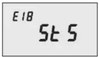
StS (Status)
Used to send to remote devices (for instance the Easy GSM Remote Control Unit - GW 90 861):
- function type and mode:
- temperature reading (every 15 minutes or each time it changes).

CdH (Heating command)
Used to send the ON/OFF command to the KNX/EIB actuators that control the heating system.

CdC (Cooling command)
Used to send the ON/OFF command to the KNX/EIB actuators that control the air conditioning system.
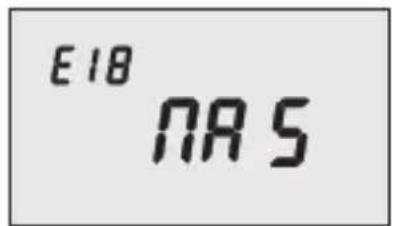
MAS (Master)
Used to send the zone thermostats enabled as "slaves" the function type (heating/air-conditioning) and mode type (OFF, Comfort, Precomfort, Economy).
When creating the above listed functions, it is not necessary to select a base unit function as the link is created automatically.
INSTALLATION INSTRUCTIONS
E1B
SLA
SLA (Slave)
This is used to set:
- the timer-thermostat function type and mode with other KNX/EIB devices from a remote position. Examples of devices which can be used are the EASY GSM Remote Control Unit, the EASY control panel and display, the EASY 4-channel contact interface etc;
- the OFF mode on the timer-thermostat, with priority over all the other commands, if an open window signal is received. When the closed window signal is received, the timer-thermostat returns to its previous function mode or to the last mode it was in when it received the forced OFF command;
- memorising the scenes, max 8: the timer-thermostat memorises the current function type, mode and setpoint.
If the "slave" channel is combined with the 4-channel contact interface (GW 90 834) the following functions are proposed on the base unit.
| Names of the functions on the Easy base unit | |
| edges Edge management | command (for window contacts) |
| scene Scene management | command |
| heating mode Thermal regulation commands (mode) | |
Refer to the Easy base unit documentation for further information on the programming procedures.
Communication KNX/EIB Bus
Power Supply By KNX/EIB bus, 29 V dc SELV + 2 1.5 V AAA
alkaline batteries to update time/date when
there is no bus power
Bus current consumption 5mA
Bus cable KNX/EIB TP1
Control elements 1 mini programming key,
10 command and programming buttons
Display elements 1 LED backlit LCD display
(timed to user intervention),
1 red programming LED
Temperature
display range 0 ÷ +45^ C
Reading elements 1 NTC
reading resolution: 0.1^
reading accuracy: ± 0.5^ to 20^
intervals between the next readings: 1 minute
Temperature regulation ranges T
FROSTPROTECT: +2 ÷ +7^ C
THIGH TEMPERATURE PROTECTION: +30÷ +40^
Other set points: +5 ÷ +40^ C
Ambit of use Indoors, dry places
Operating temperature -5 ÷ +45^ C
Storage temperature
-25÷+70°C
Relative humidity
Max 93% (no condensation)
Bus connection
Slot in terminal, 2 pin 1 mm
Protection rating
IP20
Size (L x H x W)
130 × 92 × 23 ~mm
Reference standards
Low Voltage Standard 2006/95/CE
Electromagnetic Compatibility Standard
89/336/CEE EN50090-2-2, EN60730-1
Certifications
KNX/EIB
SOMMAIRE
page
AVERTISSEMENTS GENERAUX
Contenu de la confection 72
DESCRIPTION GENERALE
Programmation minutes
P02climat - Programmation du Set-point Tz (climatisation)
This is used to set:
Communication Bus KNX/EIB
Alimentation
Par bus KNX/EIB, 29 V cc SELV + 2 piles alcalines
Cable bus KNX/EIB TP1
$$ \text {P R O T E C T I O N H A U T E S T E M P E R A T U R E S} \div + 3 0 \div + 4 0 ^ {\circ} \mathrm {C} $$
Autres set points: +5 ÷ +40^ C
Dimension (B x H x P)
$$ 1 3 0 \times 9 2 \times 2 3 \mathrm {m m} $$
Certifications KNX/EIB
INDICE
pag.
P01calef. - Programacion Set Point (tealefaction)
Cable bus KNX/EIB TP1