
GW12789VT - Alarm Clock Gewiss - Free user manual and instructions
Find the device manual for free GW12789VT Gewiss in PDF.
| Product Type | EIB/KNX control and display panel for home automation system |
| Brand | Gewiss |
| Model | GW12789VT |
| Category | Radio alarm clock (KNX control interface) |
| Dimensions (W x H x D) | 150 x 158 x 58 mm (17 mm wall protrusion) |
| Weight | Approximately 300 g (estimate) |
| Power supply | KNX/EIB bus (1.5 mA) + 230 V mains via L/N terminals |
| Power consumption | 2 W max |
| Display | 2.8" monochrome graphic LCD display, backlit (white) |
| Controls | 6 front buttons (navigation, functions), 1 contrast potentiometer |
| Main functions | KNX control (lighting, shutters, heating, alarm), timer scheduler, alarm clock, memorandum, scenarios, thermostat, clock, calendar |
| Number of communication objects | 52 (13 blocks of 4 objects) |
| Access protection | Alphanumeric password (up to 5 characters, case sensitive) |
| Maintenance and cleaning | Dry cloth, no abrasive products |
| Backup battery | Rechargeable ML1220 3 V (maintains date/time up to 72 h) |
| Operating temperature | 0 to +40 °C |
| Humidity | Max 93 % without condensation |
| Protection rating | IP20 |
| Standards | CE, KNX/EIB, EN50090, EN60950 |
Frequently Asked Questions - GW12789VT Gewiss
User questions about GW12789VT Gewiss
0 question about this device. Answer the ones you know or ask your own.
Ask a new question about this device
Download the instructions for your Alarm Clock in PDF format for free! Find your manual GW12789VT - Gewiss and take your electronic device back in hand. On this page are published all the documents necessary for the use of your device. GW12789VT by Gewiss.
USER MANUAL GW12789VT Gewiss
VALORI 16 BIT FLOATING POINT
bus KNX/EIB, 29 V dc SELV
Commands and display 74
Operating principle 74
Commands 74
Home page 75
Icons 75
Commands 76
Cursor 77
Viewing device status 77
Viewing percent values 77
Viewing time profiles (thermal regulation and timer) 78
Backlighting 78
Entering text 78
SAFETY 79
Password 79
Setting/Modifying the password 79
Cancelling the password 79
Regulating the date 80
Regulating the time 80
BASIC FUNCTIONS 80
Wakeup alarm 81
Creating or changing the wakeup alarm 81
Disabling the wakeup alarm 82
Reinstating the wakeup alarm 82
Event reminder 82
Creating an event reminder 82
Disabling the acoustic signal 83
Viewing and modifying an event reminder 83
Cancelling an event reminder 84
Adjusting and switching a dimmer light ON and OFF 85
Switching a light ON and OFF 85
Dimmer light with increase-decrease command 85
Dimmer light with percent value command 86
Opening, closing and regulating shutters and blinds 87
Shutter with up-down command 87
Shutter with percent value command .87
Priority controls and blocks 88
Forcing a light 88
Forcing a shutter or blind 89
Blocking a shutter or blind 89
Inputs 89
Possible input settings 90
Input display examples 90
Outputs 91
Possible output settings 91
Selection mode and data entry 91
CONTENTS
Activation of a scene or a scene sequence 94
Modifying the thermal regulation 95
Activating and deactivating a logic function 96
Activating and deactivating a timer 96
Burglar alarm system 97
Complete arming of the burglar alarm system 97
Partial arming of the burglar alarm system 97
Complete disarming of the burglar alarm system 98
ADVANCED FUNCTIONS 99
Scene 99
Assigning a scene to the scene system 99
Cancelling a scene from the scene system 99
Learning a scene 100
Setting 8 and 16 bit values 100
Default values 100
Editing 8 and 16 bit values 101
Programming a scene sequence 104
Creating a new scene sequence 104
Modifying a scene sequence 105
Modifying the number of repetitions of a scene sequence 107
Renaming a scene sequence 107
Cancelling a scene sequence 108
Programming the thermal regulation system 109
Programming the timers 111
Creating a new timer 111
Modifying a timer 112
Renaming a timer 113
Cancelling a timer 114
Programming logic functions 114
Creating a logic function 114
Modifying a logic function 116
Cancelling a logic function 118
Dictionaries 119
Default word list 119
Adding a word 120
Modifying a word 121
INSTALLATION 122
Warnings for KNX/EIB installations 122
Electrical connections 122
USB Port 124
Completing installation 124
CONFIGURATION 125
Menu tree 125
General settings 126
Setting the time and date 127
Assigning names to communication objects 128
Renaming objects and scenes 128
Attribution of the names downloaded from ETS 128
Names of the systems 129
Names of the rooms 129
Assigning objects to rooms 130
CONTENTS
Assigning objects to systems 130
View 131
IN SERVICE 132
Behaviour on the failure and reinstatement of the bus power supply 132
Cleaning the control panel 132
Changing the battery 132
Reset 132
Resetting the control panel 132
Reset to default settings 132
TECHNICAL SPECIFICATIONS 133
GENERAL INFORMATION
Warning! The safety of this appliance is only guaranteed if all the instructions given here are followed scrupulously. These should be read thoroughly and kept in a safe place. The Chorus products must be installed in compliance with the requisites of standard CEI 64-8 for devices for domestic use and similar, in non-dusty atmospheres and where special protection against water penetration is not required.
The GEWISS sales organisation is at your disposal for clarifications and technical information.
Gewiss SpA reserves the right to make changes to the product described in this manual at any time and without giving any notice.
Pack content
n. 1 EIB control panel and display - flush-mount - LUX
n. 1 Bus terminal
n. 1 Cover with screws
n.1 LUX design plate
n. 4 Fixing screws for box GW 24 237
n. 1 Installation and user manual
Summary
The EIB Control Panel and Display - flush-mounted - LUX allows you to interact with all the other devices in the Building Automation system, such as actuators, motor command actuators, dimmers, thermostats, timed-thermostats, input modules and the RF burglar alarm systems fitted with an bus interface (GW 20 476), etc., in a simple and user-friendly manner through the KNX/EIB bus.
The device's 52 communication objects are divided in 13 blocks with 4 objects per block. The 4 communication objects in each block are set, with ETS software, to run one of the following functions of choice:
Dimmer management
ON-OFF commands
- brightness regulation with increase / decrease or percent value (0% ÷ 100%)
status and brightness value display (0% ÷ 100%)
Shutter/blind control:
- up /down /stop / lath regulation commands
- movement commands in percent position or priority control or block
Actuator control
ON-OFF commands
ON/OFF status display
- priority control
2 relay actuator control
ON-OFF commands
ON/OFF status display
Independent objects for:
- priority controls
- store / execute scenes commands (value 0..63)
- send 1 bit / 8 bit / 16 bit values in output
- receive 1 bit / 8 bit / 16 bit values in input
The communication objects in 5 blocks can also be set, as an alternative to the above functions, for:
Burglar alarm system control (block 1)
- send arming / disarming commands
- arming enable and alarm display
Burglar alarm system control (block 2)
- send partial 1 and partial 2 commands
- display partial arming 1 and 2 status
Date and time control (block 11)
- date and time receipt from bus
- date and time transmission to bus
Thermal regulation control (block 12)
- send type (cooling/heating), mode or set point, temperature read by the panel
Thermal regulation control (block 13)
- display type (cooling/heating), mode or set point, temperature of a Slave device (thermostat or timed-thermostat)
The control panel is fitted with a 2.8" monochromatic LCD display screen, backlit with 6 buttons on the front which can be used to browse through the menu pages, view the real-time status of various devices and adjust the settings where necessary.
Access to the navigation menu can be protected by an alphanumeric password.
The device can be used as a timer on a daily or weekly basis, it can perform logic operations and can handle complex scenes, sending the commands at intervals which can be set as required.
The control panel also has time, date, event reminder and room thermostat functions.
The device is installed inside the flush-mount box GW 24 237.
Operating principle
The control panel replicates the commands, functions and the display elements available on the various KNX/EIB Building Automation system devices, through the menu and function buttons, and also provides other general information. To make this easier for the user, it is possible to access each element of the system and interact with the same, using two different logic procedures: Systems and Rooms.
This choice option allows the user to group together data and functions according to what the user wishes to achieve. For instance, if the user wishes to control the lighting system, it is recommended to select Systems Lighting, where it is possible to clearly view the status of all the lights in the house; on the other hand if the user wished to prepare the dining room for a dinner party, it is recommended to select Rooms Living from where the user can use the buttons to set the modes for lighting, shutters, climate control, scenes etc.
Commands and display
COMMANDS
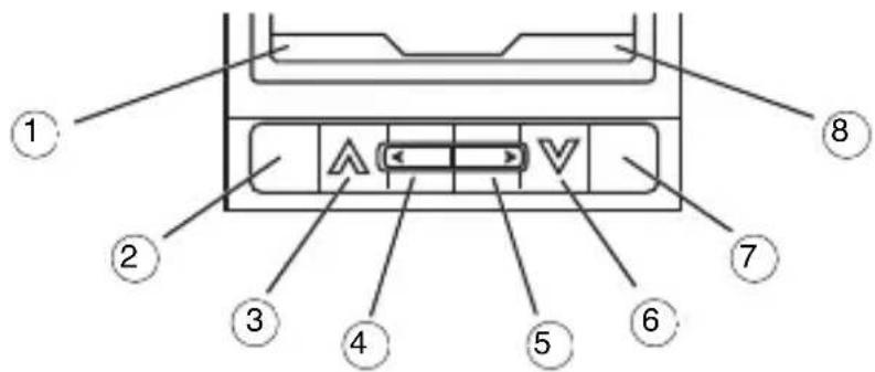
The six push buttons situated under the liquid crystal display screen are used to browse the menu and access the functions, to send commands and requests for information, to enter or select data, to configure or modify functions.
| 1 Variable function associated with the context | |
| 2 | Multi-function button 1: the related function is indicated in writing ①above it. Press and hold the button to return to the Home page. |
| 3 Upward scroll and enabling of functions represented by the icons on the Home page | |
| 4 Left scroll | |
| 5 Right scroll | |
| 6 Downward scroll and enabling of functions represented by the icons on the Home page | |
| 7 Multi-function button : the related function is indicated in writing ⑧above it | |
| 8 Variable function associated with the context | |
HOME PAGE
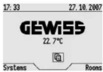
The following information is displayed on the screen in normal operating conditions:
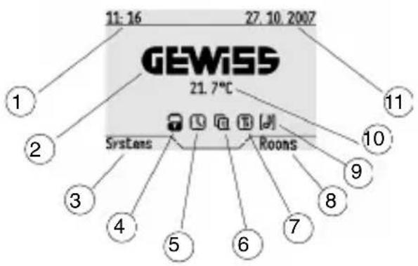
| 1 Current time |
| 2 Gewiss logo |
| 3 Function to access systems |
| 4 Burglar alarm ON indicator * |
| 5 Wake-up alarm ON indicator and access to the function |
| 6 Event reminder ON indicator and access to the function |
| 7 Timer ON indicator and access to the function |
| 8 Function to access different rooms |
| 9 Indication of activation of acoustic alarm associated with a logical function and access to logic functions list |
| 10 Room temperature |
| 11 Current date |
- The icon indicates that the burglar alarm is ON and is replaced by the icon [!] if interventions are made to the burglar alarm system.
ICONS
| Turning on a menu function / command or ON status | |
| Turning off a menu function / command or OFF status | |
| Timer enabled | |
| Event reminder enabled | |
| Burglar alarm on | |
| Burglar alarm ON | |
| Acoustic alarm for logical function | |
| Increase in light intensity using a dimmer or opening of shutters or blinds | |
| Decrease in light intensity using a dimmer or closing of shutters or blinds | |
| Stopping of variation of light intensity using a dimmer or stopping of shutter or blind movements | |
| Regulation of the blind laths during opening phase | |
| Regulation of the blind laths during closing phase | |
| Execute and learn the scenes | |
| Wakeup alarm on | |
| Heating | |
| Air conditioning | |
| Boolean value false | |
| 1 | Boolean value true |
| Priority control: override on | |
| Priority control: override off | |
| Block command on | |
| Block command off |
COMMANDS
The following abbreviations are used in function programming:
| ON | Turn on / On |
| OFF | Switch off / Off / Thermal regulation mode OFF |
| UP Raises the shutter / awning | |
| DOWN Lowers the shutter / awning | |
| INC Increases light intensity | |
| DEC Decreases light intensity | |
| STOP Stops all movement / Stops light intensity regulation | |
| EON Priority control: override ON | |
| EOFF Priority control: override OFF | |
| EUP Priority control: override UP | |
| EDWN Priority control: override DOWN | |
| DIS Priority control: deactivates override | |
| BLC Block command on | |
| UBLC Block command off | |
| AUTO Automatic thermal regulation mode | |
| ECONOMY Economy thermal regulation mode | |
| PRECOMFORT Precomfort thermal regulation mode | |
| COMFORT Comfort thermal regulation mode | |
| HEATING Heating | |
| COOLING Air conditioning | |
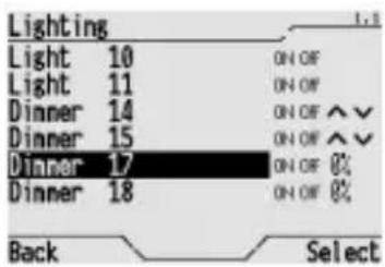
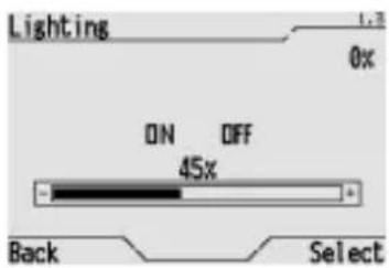
CURSOR
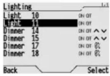
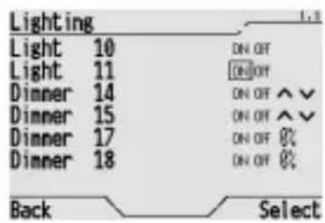
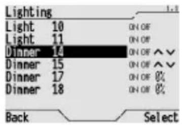
If an item on the menu is negative this is indicated by the position of the cursor.
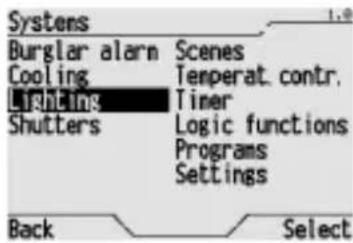
This screenshot, for instance, shows the cursor is on the "Lighting" menu item.
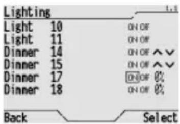
VIEWING DEVICE STATUS
The status of all devices is displayed on the screen in negative mode.
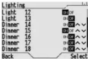
This screenshot, for instance, shows that Light 12 and Dimmer 15 are ON, whilst all the other lighting fixtures are OFF. The dimmer icon is ON even when the light intensity is less than 100% . It is not possible to view the status of the shutters, therefore the icon will never be displayed in negative mode.
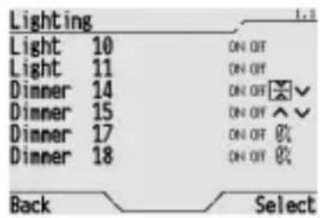
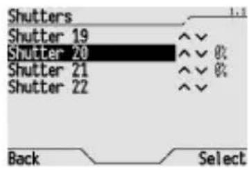
VIEWING PERCENT VALUES
For shutters or dimmers with position or light intensity percent display % ), the value is displayed next to the command. Dimmer 0% means light off and 100% means light fully on. Shutter 0% means shutter fully open and 100% means shutter fully closed. The percent value only appears if display was enabled via ETS.
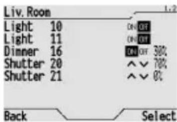
This screenshot, for example, shows that the Dimmer 16 is on and its intensity is 30% . Of the two shutters, one is partially closed (Shutter 20, 70% closed) while the other is fully open (Shutter 21, 0% closed).
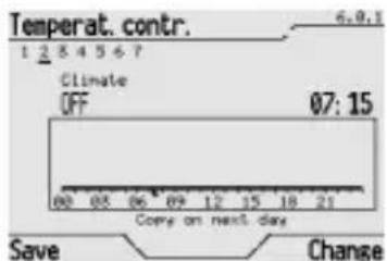
VIEWING TIME PROFILES (THERMAL REGULATION AND TIMER)
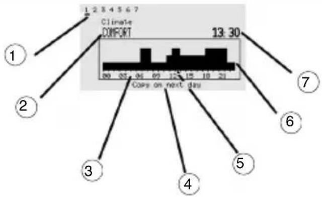
| 1 Day of the week |
| 2 Thermal regulation mode on, status and value associated with the timer at the selected time. |
| 3 Daily time scale |
| 4 Copy settings to the next day |
| 5 Timer cursor |
| 6 Daily settings graphics |
| 7 Time relative to the cursor |
BACKLIGHTING
The monochromatic graphic display is backlit by a white light. The backlighting is activated by pressing any of the front push buttons and automatically turns off 30 seconds after the last button is pressed.
ENTERING TEXT
To enter text, use keys ▲▼. The letters are selected using the and buttons which scroll the letters and numbers available. The sequence is as follows:


*[spazio] 0123456789ABCDEFGHIJKLMNOPQRSTUVWXYZabcdefghijklmnopqrstuvwxyz


The button cancels the last displayed letter, whilst the button moves forward one space.
SECURITY
Password
For extra security it is possible to set a password to access the navigation menu. This precaution is useful when, for instance, the control panel is placed in an area which is frequented by many people, when it also controls the burglar alarm or when you want to set a limit for the number of people who are allowed to configure or change the Building Automation settings.

The password protection is enabled each time you return to the Home Page or after timeout (see General settings section).
WARNING: once the password has been set, all access to the navigation menu will require the password to be entered.
SETTING/MODIFYING THE PASSWORD
The password can contain up to 5 alphanumeric characters. The control panel distinguishes between upper and lower case: for instance "larch", "Larch" and "LARCH" are all different passwords. To set or modify the password, please proceed as follows:
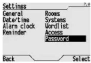
From the Home page, Systems/Rooms Settings Password.
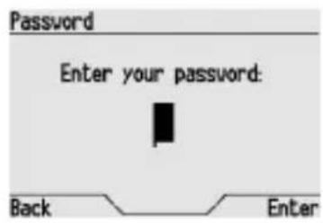
Enter the correct password on the displayed screen (please consult the Entering text section for information on how to key in the letters and numbers) and press Enter to confirm.
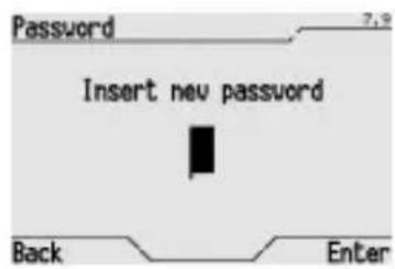
If no password had been set for the control panel this procedure is complete, on the contrary a pop-up will appear to enter the new password. Enter the new password and press Enter to confirm.

WARNING: write the password down and store in a safe place, because it will always be needed to access the menu from now on.
To cancel an existing password, enter the old password, leave the new password field empty, and press Enter to confirm.

WARNING: once the password has been cancelled, access to the navigation menu is open to everyone.
Regulating the time
The time profiles for the thermal regulation and programmed activation of the timer functions are all controlled by the clock on the control panel. The time set on this clock is displayed on the Home Page on the control panel.
The control panel does not automatically adjust to changes from winter to summer time, or vice versa, so this must be adjusted manually when necessary.
To regulate the time, please proceed as follows:
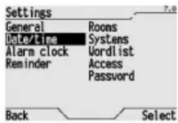
From the Home page, Systems/Rooms Settings Date/time.
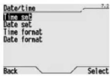
Select Time set.
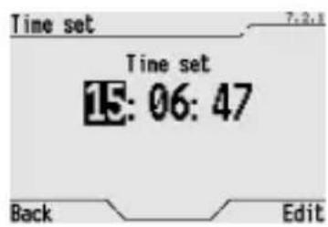
Use the and buttons to scroll the hours, minutes and seconds. Use the and buttons to increase or decrease the value displayed. Press Edit to confirm the new time. Select Back to exit without changing the time.
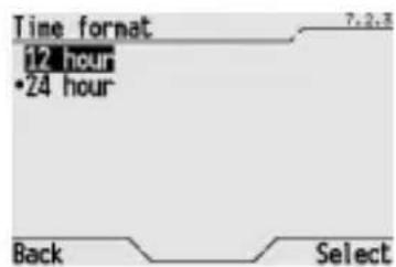
It is also possible to change the time display format (24 hour clock or 12 hour clock). Select Time format, then select the desired format (indicated with a dot) and press Select to confirm.
Time can be received in input via KNX/EIB bus using communication object n^41 - Day/Hour input (DPT 10.001). Time can be transmitted to the bus through communication object n^40 - Day/Hour output (DPT 10.001).
Regulating the date
The daily profiles for the thermal regulation and programmed activation of the timer functions are all controlled by the calendar on the control panel. The date set is displayed on the Home Page on the control panel. To regulate the date, please proceed as follows:
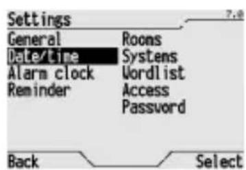
From the Home page, Systems/Rooms > Settings > Date/time.
BASIC FUNCTIONS
Select Date set.
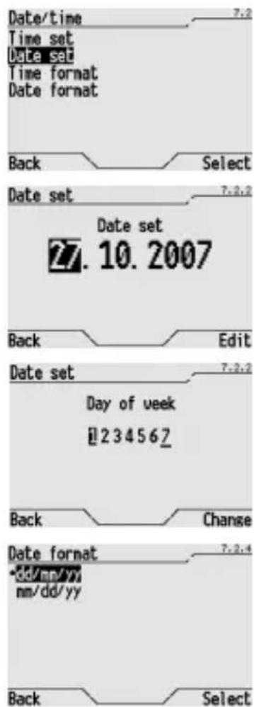
Use the and buttons to scroll the days, months and year. Use the and buttons to increase or decrease the value displayed. Press Edit to confirm the new date. Select Back to exit without changing the date.
It is also possible to set the day of the week (1 = Monday ... 7 = Sunday). Use the and buttons to select the day of the week, and press Change to confirm.
It is also possible to change the date display format (day/month/year or month/day/year). Select Date format, then select the desired format (indicated with a dot) and press Select to confirm.
The date can be received in input via KNX/EIB bus using communication object n^43 - Date input (DPT 11.001). The date can be transmitted to the bus through communication object n^42 - Date output (DPT 11.001).
Wakeup alarm
It is possible to set a wakeup alarm on the control panel, which will ring every day at the same time, or ring once and then be disabled. The alarm time is memorised by the control panel and the wakeup alarm can be enabled or disabled as necessary.
The icon indicates that the wakeup alarm is ON and is displayed on the Home Page on the control panel.
CREATING OR CHANGING THE WAKEUP ALARM
To create a new wakeup alarm, or change the one already set, please proceed as follows:
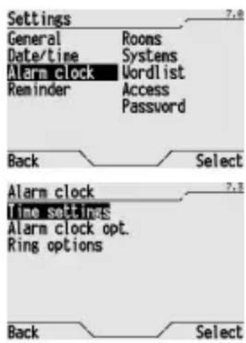
From the Home page, Systems/Rooms > Settings > Alarm clock.
Select Time settings to enter a new wakeup time or change the one already set. Press Select to confirm.
BASIC FUNCTIONS
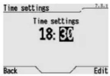
Set the new time, in hour:minutes format using the and buttons and confirm by pressing Edit.
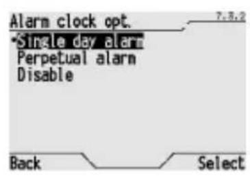
Select Alarm clock opt. On the screen, it is possible to set a wakeup alarm to ring once or every day at the same time. The default setting is Disable. Select one of the activation options (indicated with a dot) and press Select to confirm.
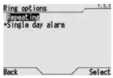
Select Ring options. On the screen, it is possible to select how the alarm should ring:
- Single day alarm: the wakeup alarm rings for one minute and is then disabled forever;
- Repeating: the alarm rings for one minute five times, at five minute intervals; the repetition cycle is interrupted when the alarm is switched off.
DISABLING THE WAKEUP ALARM
When the wakeup alarm is ringing it can be switched off from the Home Page selecting icon and pressing or If the wakeup alarm is enabled, but is not yet ringing, select the icon and press the or buttons to access the menu and modify or disable the alarm.
To permanently disable the wakeup alarm, select Disable on the Alarm clock opt. menu (the wakeup alarm will be disabled but the set time will not be cancelled).
REINSTATING THE WAKEUP ALARM
To reinstate the previously disabled wakeup alarm Single day alarm or Perpetual alarm on the Alarm clock opt. menu (the wakeup alarm will be enabled at the previously set time).
Event reminder
The control panel can also be used to store a short event reminder message, similar to an electronic Post-it® concept. The event reminder can be used, for instance, to exchange messages with other members of the family or as a timed ringing notepad. It is possible to memorise up to 8 events, each with their own title. The icon indicates that the event reminder is ON and is displayed on the Home page on the control panel.
CREATING AN EVENT REMINDER
To create a new event reminder, please proceed as follows:
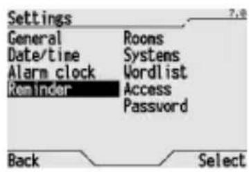
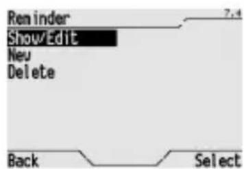
From the Home page, Systems/Rooms Settings Reminder.
BASIC FUNCTIONS
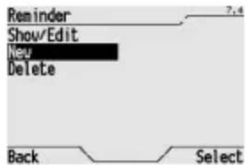
Select New and press Select to confirm.
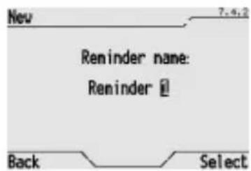
Enter the title of the event on the displayed window, that can contain up to 20 characters (please consult the Entering text section for information on how to key in the letters and numbers). Press Select to confirm.
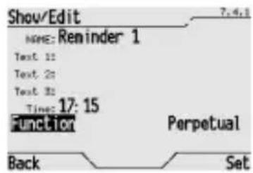
Enter the following data on the displayed window:
- the event reminder text (up to three rows, with 20 characters per row; please consult the Entering text section for information on how to key in the letters and numbers).
- the event reminder alarm time, using the hour:minute format, which will enable an acoustic signal at the set time;
- the function mode: standard (the event reminder is activated every day at the set time) or extraordinary (the event reminder is activated just once, at the set time, then disabled); use the and buttons to select the function mode.
Use Set and Back to move from one row to another.
Press Set to confirm.
DISABLING THE ACOUSTIC SIGNAL
To disable the event reminder acoustic alarm, select Back on the displayed window. Press Back again to disable viewing of event reminders.
VIEWING AND MODIFYING AN EVENT REMINDER
To view and modify an event reminder, please proceed as follows:

From the Home page, Systems/Rooms > Settings > Reminder.
Select Show/Edit and press Select to confirm.
BASIC FUNCTIONS
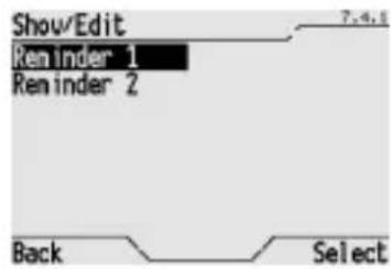
All the memorised event reminders are displayed on the screen. Use the and buttons to select the event reminder you wish to view, and press Select to confirm.
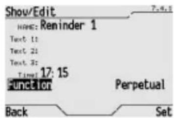
The name of the event appears. Press Select to confirm. Then repeatedly press the Set button: each time the button is pressed it displays an element of the event reminder (Text 1, Text 2, Text 3, Time and Fuction). When an element is displayed, it can be modified following the same procedure used to create the event reminder.
When you have finished, press Set to save the changes or Back to exit and maintain the previous settings.
It is possible to access the window to create and modify an event reminder from the Home page selecting the corresponding icon and pressing and buttons. The icon is only displayed if an event reminder is enabled.
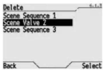
CANCELLING AN EVENT REMINDER
To cancel an event reminder, please proceed as follows:
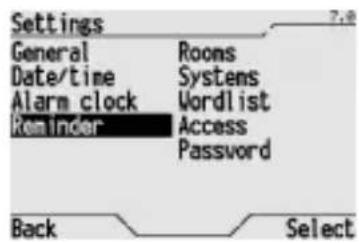
From the Home page, Systems/Rooms Settings Reminder.
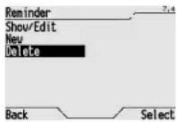
Select Delete and press Select to confirm.
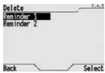
All the memorised event reminders are displayed on the screen. Use the and buttons to select the event reminder you wish to delete, and press Select to confirm.
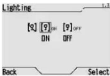
Switching a light ON and OFF
To switch a light ON or OFF, please proceed as follows:
Select Systems or Rooms from the Home page, then the system or room which incorporates the light in question, and then highlight the light using the and buttons.
Highlight the action to be set using the and buttons:
- ON to switch the light on, or
- OFF to switch the light off and press Select to confirm.
If you press Select with the name of the item highlighted, a new window will appear where you can view and control just the one light.
Adjusting and switching a dimmer light ON and OFF
DIMMER LIGHT WITH INCREASE-DECREASE COMMAND
To regulate or switch a dimmer light set when programming ETS with the increase-decrease command on or off, proceed as follows:
Select Systems or Rooms from the Home page, then the system or room which incorporates the light in question, and then highlight the light using the and buttons.
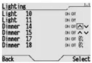
Highlight the action to be set using the and buttons:
- ON to switch the light on completely, or
OFF to switch the light off completely, or
to increase the intensity of the light, or
to decrease the intensity of the light and press Select to confirm.
BASIC FUNCTIONS
If you have chosen to increase or decrease the intensity of the light, the relative icon will become 12 whilst the light intensity will start to adjust continuously. Press Select when the light level reaches the intensity you require.
If you press Select with just the light highlighted, a new window will appear where you can view and control just the one light. If display was enabled via ETS, the current intensity percent value will appear in the top right corner.
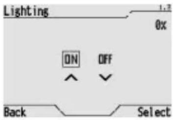
DIMMER LIGHT WITH PERCENT VALUE COMMAND
To regulate or switch a dimmer light set when programming ETS with the percent value command on or off, proceed as follows:
Select Systems or Rooms from the Home Page, then the system or room which incorporates the light in question, and then highlight the light using the and buttons.
Highlight the action to be set using the and buttons to switch the light on or off:
- ON to switch the light on completely, or
- OFF to switch the light off completely and press Select to confirm.
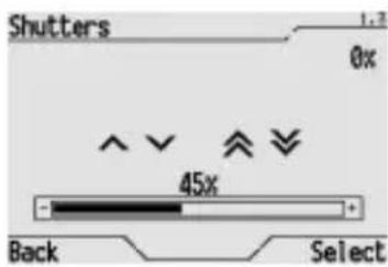
To adjust intensity, press the Select button with the light selected. A window will appear where that light can be displayed and controlled.
Highlight the horizontal cursor using the , , and buttons. Light intensity is adjusted using the and buttons and must be confirmed by pressing Select.
The dimmer percent value is display as a graph on the cursor and as a numeric value over the cursor.
If display was enabled via ETS, the current dimmer percent value will appear in the top right corner.
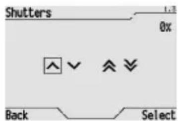
Opening, closing and regulating shutters and blinds
SHUTTER WITH UP-DOWN COMMAND
To regulate, open or close a shutter or blind set when programming ETS with the up-down command, proceed as follows:
Select Systems or Rooms from the Home page, then the system or room which incorporates the shutter or blind in question, and then highlight the shutter or blind using the and buttons.
Highlight the action to be set for the shutter or blind using the and buttons:
to open a shutter or raise a blind, or
to close a shutter or lower a blind, or
- to regulate the blind laths during the opening phase, or
to regulate the blind laths during the closing phase and press Select to confirm.
If you have chosen to open or close a shutter (or raise or lower a blind), the relative icon will become × whilst the shutter (or blind) will start to move. Press Select to stop the movement before the shutter (or blind) is completely open (completely up) or closed (completely down).
If you press Select with the name of the item highlighted, a new window will appear where you can view and control just this specific shutter or blind.
From this window it is possible to regulate the angle of the blind laths.
Select the relative symbol (on) and repeatedly press Select until the laths reach the desired inclination angle (each time you press the button the lath moves one pitch forward).
If display was enabled via ETS, the current shutter or blind closing percent value will appear in the top right corner.
SHUTTER WITH PERCENT VALUE COMMAND
To open, close and regulate a shutter or blind set when programming with ETS with the percent command (alternative to the priority control and block control), proceed as follows:
Select Systems or Rooms from the Home page, then the system or room which incorporates the shutter or blind in question, and then highlight the shutter or blind using the and buttons.
BASIC FUNCTIONS
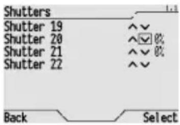
Highlight the action to be set for the shutter or blind using the and buttons:
to open a shutter or raise a blind, or
to close a shutter or lower a blind, or
- to regulate the blind laths during the opening phase, or
to regulate the blind laths during the closing phase and press Select to confirm.
If you have chosen to open or close a shutter (or raise or lower a blind), the relative icon will become × whilst the shutter (or blind) will start to move. Press Select to stop the movement before the shutter (or blind) is completely open (completely up) or closed (completely down).
If you press Select with the name of the item highlighted, a new window will appear where you can view and control just this specific shutter or blind.
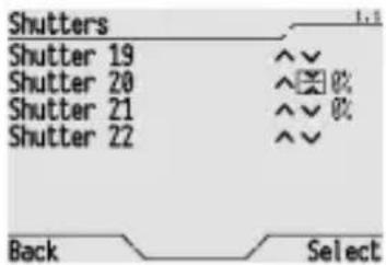
Shutter or blind opening and blind lath tilt can be regulated in the window.
Highlight the command to be used with the , , and buttons.
The horizontal cursor is used to set a shutter or blind closing percent. The value can be regulated using the and buttons and must be confirmed by pressing Select. The closing percent is displays as a graph on the cursor and as a number over the cursor (0% = shutter or blind fully open, 100% = shutter or blind fully closed).
To regulate laths, select the relative symbol (or × ) and repeatedly press Select until the laths reach the desired inclination angle (each time you press the button the lath moves one pitch forward).
If display was enabled via ETS, the current shutter or blind closing percent value will appear in the top right corner.
Priority controls and blocks
FORCING A LIGHT
If set when programming with ETS, a light can be controlled via priority control (override). When priority control is on, the device that controls the light (actuator or dimmer) ignores all other commands it receives. Priority controls can be set "on" and "off": with "on" the light is always on, ignoring off commands that it may receive from other devices, the timer or scenes; with "off", the light is always off. Switch off the priority control to return the light to normal operations. Priority controls for lights can be used, for example, when lights need to left on for cleaning or maintenance.
To switch a priority control on or off, open the light window and highlight the command to use with the , , and buttons:
- ON to keep the light always on, or
- OFF to keep the light always off, or
- to switch off the priority control and press Select to confirm.
BASIC FUNCTIONS
FORCING A SHUTTER OR BLIND
If set when programming with ETS, a shutter or blind can be controlled via priority control (override). In ETS settings, the shutter priority control is an alternative to the percent command and block command. When priority control is on, the device that controls the shutter or blind ignores all other commands it receives.
Priority controls can be set "down" and "up": with "down" the shutter or blind is always closed, ignoring commands that it may receive from other devices, the timer or scenes; with "up", the shutter or blind is always open. Switch off the priority control to return the shutter or blind to normal operations. Priority controls for shutters can be used, for example, when needed for cleaning or maintenance.
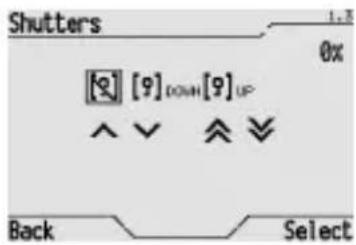
To switch a priority control on or off, open the shutter or blind window and highlight the command to use with the , , and buttons:
- DOWN to keep the shutter or blind always down, or
- UP to keep the shutter or blind always up, or
to switch off the priority control and press Select to confirm.
BLOCKING A SHUTTER OR BLIND
If set when programming with ETS, a shutter or blind can receive a block command. In ETS settings, the shutter block command is an alternative to the percent command and priority control. With the block command, the shutter or blind reaches the position set when programming with ETS and remains there, ignoring all other commands it receives. Switch off the block command to return the shutter or blind to normal operations. The shutter or blind block command can be used, for example, to move it and keep it in a safe position.
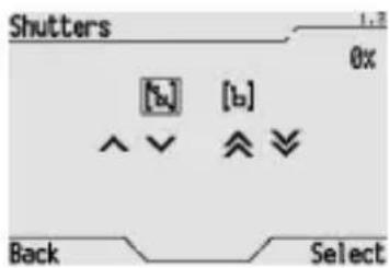
To switch the block command on or off, open the shutter or blind window and highlight the command to use with the , , and buttons:
- to block the shutter or blind, or
- to switch off the shutter or blind block command and press Select to confirm.
Inputs
Control panel and display communication objects can be set via ETS as inputs or outputs. When set as inputs, they can receive information on the status of other devices or the value of specific parameters selected during programming. Thus, the thermal regulation system operating mode, temperature, light or other actuator status, awning position, meter reading and much more information can be displayed on the panel.
The value controlled by the single input can be 1 bit, 8 bit or 16 bit and is set when programming with ETS. The 1 bit, 8 bit or 16 bit size also sets the type and maximum size of the value controlled.
BASIC FUNCTIONS
POSSIBLE INPUT SETTINGS
| input value | use | graphic representation | admitted values |
| 1 bit Boolean 1, 0 | 1 0 | ||
| 1 bit Heating / Air conditioning Heating, Air conditioning | 89 | 0 ÷ 255 | |
| 1 bit ON / OFF | 35% | 0% ÷ 100% | |
| 8 bits Generic whole value | AUTO | Auto, Economy, Comfort, Precomfort, OFF | |
| 8 bits Percent value (%) | |||
| 8 bits Thermal regulation mode | |||
| 16 bits Generic value without sign | 27580 | 0 ÷ 65535 | |
| 16 bits Generic value with sign | -4892 | -32768 ÷ +32767 | |
| 16 bits Generic value with floating point | 368.5 | -99999,9 ÷ +99999,9 | |
| 16 bits Temperature value with floating point | 20.3 °C | -99,9 °C ÷ +99,9 °C |
Temperature is displayed in Celsius.
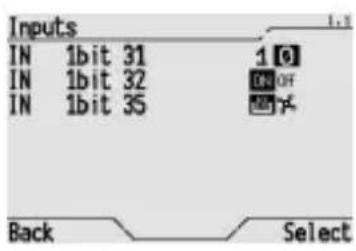
INPUT DISPLAY EXAMPLES
1 bit inputs: input 31 displays a False boolean value, input 32 displays the ON status of an object, for example, a light, input 35, lastly, signals that the thermal regulation system is set to operate in heating mode.
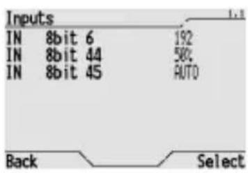
8 bit inputs: input 6 displays a generic whole value, input 44 displays a percent value, for example, a dimmer off, input 45, lastly, signals that the thermal regulation operating mode is Automatic.
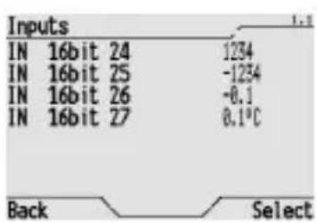
16 bit inputs: input 24 displays a generic whole value, input 25 displays a generic value with a sign, input 26 displays a generic value with decimal points, input 27 displays a temperature in degrees Celsius.
BASIC FUNCTIONS
Outputs
Control panel and display communication objects can be set via ETS as inputs or outputs. When set as outputs, they can control other devices selected during programming or send them operating values.
The value controlled by the single output can be 1 bit, 8 bit or 16 bit and is set when programming with ETS. 1 bit, 8 bit or 16 bit size also sets the type of command or value that can be sent.
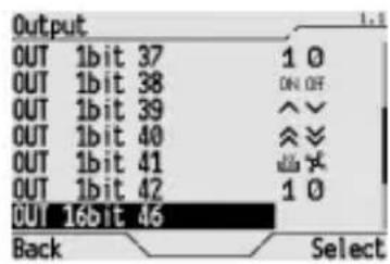
POSSIBLE OUTPUT SETTINGS
| output value | use | graphic representation | admitted values |
| 1 bit Boolean 1, 0 | 10 | ||
| 1 bit Heating / Air conditioning Heating, Air conditioning | 89 | ||
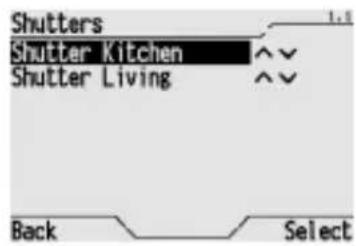
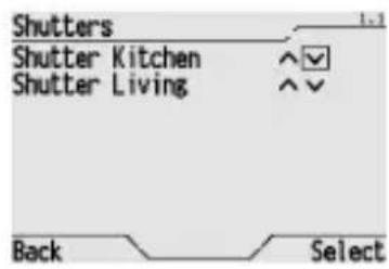
| 1 bit Shutters movement Up, Down | ^√ | ||
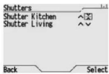
| 1 bit Blind lath regulation Regulation Up, Regulation Down | ×√ | ||
| 1 bit ON / OFF | ON OFF | ON, OFF | |
| 8 bits Generic whole value | 089 | 0÷255 | |
| 8 bits Percent value (%) | 35% | 0%÷100% | |
| 8 bits Thermal regulation mode | AUTO | Auto, Economy, Comfort, Precomfort, OF | |
| 16 bits Generic value without sign | 27580 | 0÷65535 | |
| 16 bits Generic value with sign | -15893 | -32768÷+32767 | |
| 16 bits Generic value with floating point | 368.5 | -99999,9÷+99999,9 | |
| 16 bits Temperature value with floating point | 20.3 °C | -99,9 °C÷+99,9 °C | |
| 16 bits Time value (floating point) | 01:27:41 | 00:00:00÷99:59:59 |
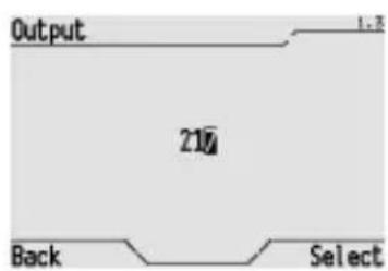
SELECTION MODE AND DATA ENTRY
To select a value for an output or to enter a value, select the output to be set from the output list and confirm the selection by pressing Select. A different window opens for each output type where the value can be selected or entered.
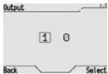
1 bit Boolean output: highlight the Boolean value to be sent using the and buttons and confirm by pressing Select.
BASIC FUNCTIONS
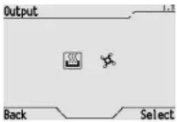
1 bit output, heating/air conditioning: highlight the type of thermal regulation system operation to be switched on using the and buttons and confirm by pressing Select.
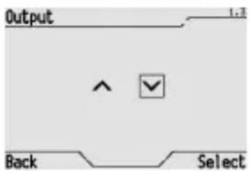
1 bit output, shutter movement: highlight the shutter or blind movement to be switched on using the and buttons and confirm by pressing Select.
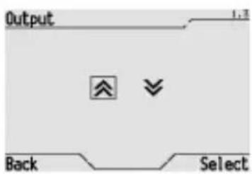
1 bit output, lath regulation: highlight the blind lath movement to be switched on using the and buttons and confirm by pressing Select.

1 bit output, ON/OFF: highlight the command to be sent using the and buttons and confirm by pressing Select.
8 bit output, generic whole value: select and change the unit, tenths and hundreds using the , , and buttons until the required value is set; confirm by pressing Select.
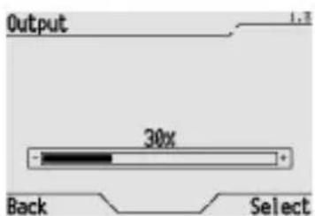
8 bit output, percent value: modify the percent value using the and buttons and confirm by pressing Select.
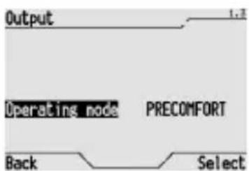
8 bit output, operating mode: select the operating mode to be set for the thermal regulation system using the and buttons and confirm by pressing Select.
BASIC FUNCTIONS

16 bit output, generic whole value: select and change the unit, tenths, hundreds and thousands using the , , and buttons until the required value is set; confirm by pressing Select.
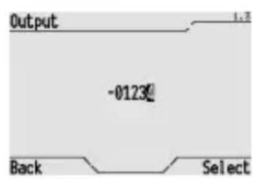
16 bit output, value with sign: select and change the unit, tenths, hundreds and thousands in addition to the sign using the , , and buttons until the required value is set; confirm by pressing Select.
16 bit output, value with decimal point: select and change the unit, tenths, hundreds and thousands in addition to the sign and decimal points using the , , and buttons until the required value is set; confirm by pressing Select.
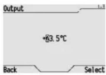
16 bit output, temperature: select and change the degrees Celsius unit and tenths in addition to the sign and decimal points using the , , and buttons until the required temperature is set; confirm by pressing Select.
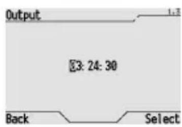
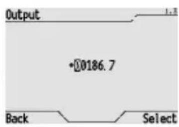
16 bit output, time: select and change the hour, minutes and seconds using the , , and buttons until the required time is set; confirm by pressing Select.
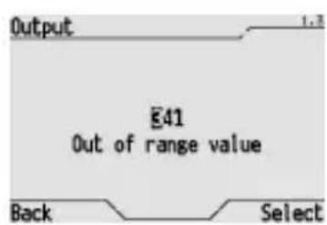
If the value entered in the previously described data entry windows are not within the admitted range, the "Out of range value" error message temporarily appears. This screenshot, for example, shows the error caused by the value 341, higher than 255 which is the maximum admitted value for an 8 bit output.
BASIC FUNCTIONS
Activation of a scene or a scene sequence
To activate a scene or scene sequence, please proceed as follows:
From the Home page, Systems/Rooms Scenes.
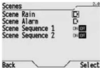
Select the scene to be activated highlighting the corresponding icon in the list, using the and buttons. Press Select to confirm.
If you wish to use a scene sequence, use the and buttons to highlight the ON or OFF icon which corresponds to the action to be performed (ON activates the scene sequence, OFF interrupts the current scene sequence).
If a scene sequence is interrupted, the status of the objects which comprise the scene remains the same as they were before the interruption command was given (for instance, if a light was on, it will stay on). When you activate a scene sequence which was previously interrupted, the sequence of the commands starts from the beginning again, and does not restart from where it was interrupted.
BASIC FUNCTIONS
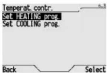
Modifying the thermal regulation
To modify the thermal regulation system functions, please proceed as follows:
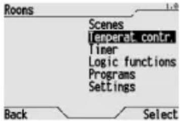
From the Home page, Systems/Rooms Temperat. contr.
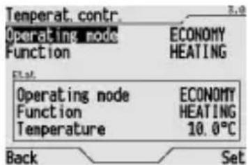
If enabled via ETS, the "Master thermal regulation with mode" function is operated as follows. To change operating mode, use the and buttons to select Operating mode and then use the and buttons to select either:
- OFF, which switches the system off (except the frostprotect and high temperature function modes);
- ECONOMY, PRECOMFORT and COMFORT which activates the corresponding temperature set points set on the slave devices;
- AUTO, where the timed-thermostats configured as slave devices implement their daily/weekly temperature profile (the thermostats configured as slave devices do not perform any type of command);
- ENABLE PROG., where all the slave devices implement the daily/weekly temperature profile set on the control panel.
Press Set to confirm.
To change operating mode, use the and buttons to select Function and then use the and buttons to select either:
HEATING or
COOLING.
Press Set to confirm.
If enabled via ETS, the Display thermal regulation with mode display function, displays the mode, function type and temperature read for a controlled Slave device in a box.
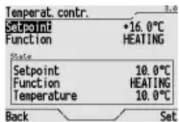
If the thermal regulation system is controlled by set point, after selecting Setpoint with the and buttons, you can use the and buttons to select the set point to be used from the 8 saved values or the ENABLE PROG. command.
If enabled via ETS, the Display thermal regulation with set point display function, displays the current set point, function type and temperature read for a controlled Slave device in a box.
NOTE: when a time profile is enabled with the ENABLE PROG. command, the mode and set point set when the profile was enabled are immediately sent to the bus.
For further information on thermal regulation and to set the daily/weekly time profile, see paragraph Programming the thermal regulation system, to change set points, see paragraph Setting 8 and 16 bit values.
Activating and deactivating a timer
To activate or deactivate a timer, please proceed as follows:
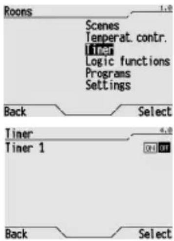
From the Home page, Systems/Rooms Timer.
Select the timer to be activated or deactivated highlighting it in the list, using the and buttons. Using the and buttons, select the icon:
ON to activate the timer
OFF to deactivate the timer
and press Select to confirm.
Press Back to return to the previous menu.
NOTE: when a timer is activated, the communication object associated with the timer is sent to the bus for the first time when the set time profile changes for the first time.
For further information on the creation and programming of a timer, please refer to the Timer programming section.
Activating and deactivating a logic function
To activate or deactivate a logic function, please proceed as follows:
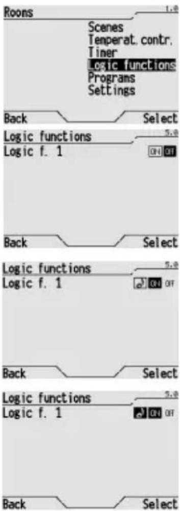
From the Home page, Systems/Rooms > Logic functions.
Select the logic function to be activated or deactivated highlighting it in the list, using the and buttons.
Use the and buttons to select the icon:
- ON to activate the logic function
OFF to deactivate the logic function
and press Select to confirm.
Press Back to return to the previous menu.
If an audible alarm was associated with a logic function, the symbol will appear next to the function name.
The logic function icon that generated the alarm signal will be highlighted. Select the icon to cancel the saved alarm. The icon returns to normal status.
For further information on the creation and programming of a logic function, please refer to the Programming logic functions section.
Burglar alarm system

WARNING: If the control panel is used to control the burglar alarm system, it is essential to enter a password on the control panel, as explained in the Password section. This is an essential security measure otherwise anyone can access the control panel and disarm the burglar alarm system.
The operations described below are significant if the options "burglar system base functions" (Block 1) and "partial operating mode burglar system" (Block 2) were selected in ETS settings.
COMPLETE ARMING OF THE BURGLAR ALARM SYSTEM
To arm the burglar alarm system completely, please proceed as follows:

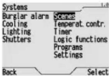
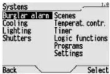
From the Home page, Systems Burglar alarm.
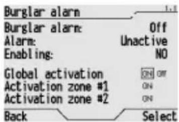
Highlight ON next to Global activation in the window that appears using the , , and buttons and confirm by pressing Select.
The arming of the burglar alarm is displayed by the writing Burglar alarm: Global activat, highlighting the ON icon next to Global activation and on the Home page by icon
If the burglar alarm system is not armed it is necessary to check that the alarm unit is enabled correctly, checking that the "YES" icon next to Enabling is visible (if the "NO" icon is visible the alarm unit is not enabled for arming and the alarm unit must be checked to find out why).
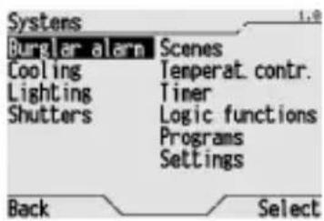
PARTIAL ARMING OF THE BURGLAR ALARM SYSTEM
To partially arm the burglar alarm system completely, please proceed as follows:
From the Home page, Systems Burglar alarm.
On the screen use the , , and buttons to select ON next to Activation zone #1 or Activation zone #2, according to the zone to be armed, and press Select to confirm.
The arming of the burglar alarm is displayed by the writing Burglar alarm: Activat. zone #1 or Activat. zone #2, highlighting the ON icon next to Activation zone #1 or Activation zone #2 and on the Home page by icon
If the burglar alarm system is not armed it is necessary to check that the alarm unit is enabled correctly, checking that the "YES" icon next to Enabling is visible (if the "NO" icon is visible the alarm unit is not enabled for arming and the alarm unit must be checked to find out why).
COMPLETE DISARMING OF THE BURGLAR ALARM SYSTEM
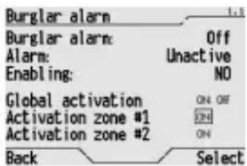
To disarm the burglar alarm system completely, please proceed as follows:
From the Home page, Systems >Burglar alarm.
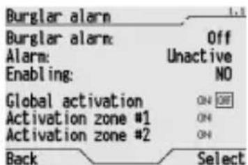
Highlight OFF next to Global activation in the window that appears using the , , and buttons and confirm by pressing Select.
It is not possible to partially disarm the burglar alarm system. If this is required, you must first disarm the entire system, then rearm the specific zones required.
To disarm the burglar alarm system it is also possible to access the control page from the Home Page selecting icon and pressing or to confirm.
When the burglar alarm is armed this is displayed on the Home page by the
If the burglar alarm goes off, the burglar alarm icon will be replaced by the icon. The control panel will emit an acoustic signal when the burglar alarm is armed.
Press the or buttons to switch off the acoustic signal. Press the or buttons again, with the selector on the icon on the Home page, to access the burglar alarm system control page.
After resetting the burglar alarm, the icon is no longer displayed.
If the "burglar system base functions" was set via ETS but not "partial operating mode burglar system", the "Activation zone #1" and "Activation zone #2" ON command icons are not displayed and the relevant commands are disabled.
WARNING: We recommend you do not only set the "partial operating mode burglar system" option since alarm signalling will not be available and alarm arming information would not be significant in the event of total system arming by a burglar alarm system device (for example, remote control).
ADVANCED FUNCTIONS
Scene
A scene is a personalised combination of light and shutter device status, dimmer light regulation values, thermostat thermal regulation modes, etc. that can be saved and recalled with a single command.
A scene is created by suitably setting the communication objects via ETS and assigning it a number between 0 and 63.
To activate a scene, please refer to the Activating a scene or a scene sequence section.
ASSIGNING A SCENE TO THE SCENE SYSTEM
A communication object dedicated to a scene run / save function is automatically attributed to the Scene system upon configuration via ETS.
To reassign a scene to the Scene system after cancellation, please proceed as follows:
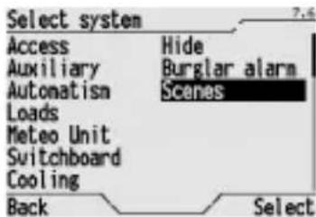
From the Home page, Systems/Rooms Settings Systems Scenes.
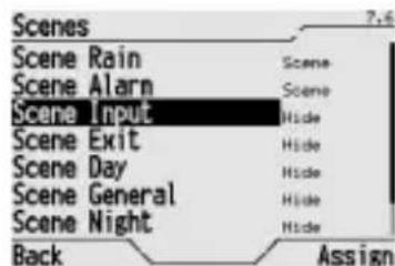
Use the and buttons to select the scene you wish to assign, and press Assign to confirm.
CANCELLING A SCENE FROM THE SCENE SYSTEM
To cancel a scene from the scene system, please proceed as follows:
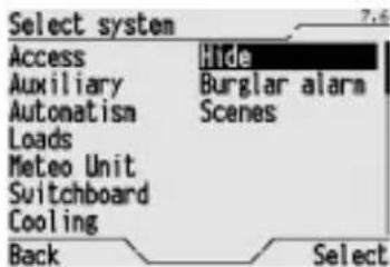
From the Home page, Systems/Rooms > Settings > Systems > Hide.
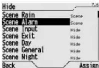
Use the and buttons to select the scene you wish to delete, and press Assign to confirm.
The scene is not actually cancelled, but simply stored on hold, and can be assigned to the Scene system again when required.
A scene that is not assigned to the Scene system is not displayed in the list of those which can be enabled, or those that can be learned.
LEARNING A SCENE
The scene learning process consists in the memorising of the current status of all the devices which are part of the same scene. To learn a scene, please proceed as follows:
Manually set the status of all the devices (lights, shutters, thermostats etc.) that are part of the scene function you have created.
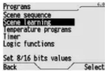
From the Home page, Systems/Rooms Programs Scene learning.
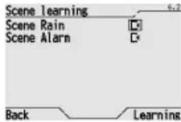
Use the and buttons to select the scene you want to learn, highlighting the corresponding icon and confirm by pressing Learning. Select Back if you wish to exit without memorising the scene.

Setting 8 and 16 bit values
8 and 16 bit objects can be used in scene sequence, temperature profile, multilevel timer and logic function programming functions described below and can assume different values. A list of 8 values can be freely set for each of these 7 types of objects which will be used in all programming functions.
DEFAULT VALUES
Panel control lists and display are factory set with the following default values. These value lists can be modified as explained in the Editing 8 and 16 bit values section.
| Value | LIST | ||||||
| 8 bit values [0..255] | 8 bit values [0%.100%] | Time [sec] | Temperature [°C] | 16 bits unsigned | 16 bits signed | 16 bits float | |
| Val1 000 000% | 00:00:10 +05.0 | °C 00000 -32767 -00100.0 | |||||
| Val2 035 015% | 00:00:30 +16.0 | °C 10000 -30000 -00075.0 | |||||
| Val3 070 030% | 00:01:00 +18.0 | °C 20000 -20000 -00050.0 | |||||
| Val4 110 045% | 00:05:00 +20.0 | °C 30000 -10000 -00025.0 | |||||
| Val5 145 060% | 00:15:00 +24.0 | °C 40000 +00000 +00000.0 | |||||
| Val6 185 075% | 00:30:00 +26.0 | °C 50000 +10000 +00050.0 | |||||
| Val7 220 090% | 01:00:00 +28.0 | °C 60000 +20000 +00070.0 | |||||
| Val8 255 100% | 03:00:00 +35.0 | °C 65535 +32768 +00100.0 | |||||
EDITING 8 AND 16 BIT VALUES
To edit values saved in the 8 and 16 bit value list, please proceed as follows:
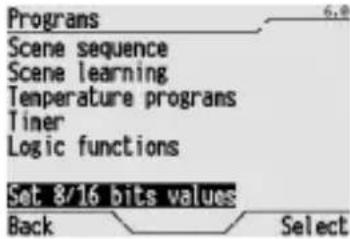
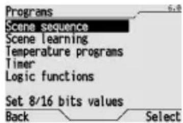
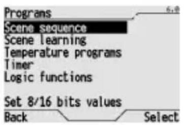
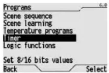
From the Home page, Systems/Rooms Programs Set 8/16 bits values.
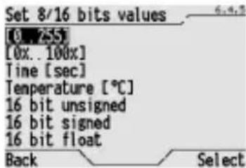
Use the and buttons to highlight the type of object whose list is to be edited and confirm by pressing Select.
A window opens that lists current values. Each value can be selected and edited. Selection and edit windows specific to each object type are illustrated below.
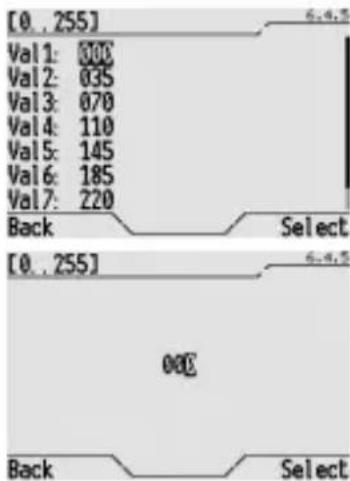
8 BIT VALUE Use the and buttons to select the value to be edited and press Select to confirm. Use the , , and buttons in the window that opens to enter the 8 bit value and confirm by pressing Select. Admitted values 0÷ 255
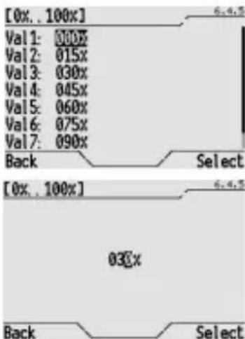
PERCENT VALUE Use the and buttons to select the value to be edited and press Select to confirm. Use the, , and buttons in the window that opens to enter the percent value and confirm by pressing Select. Admitted values: 0% ÷ 100%
ADVANCED FUNCTIONS
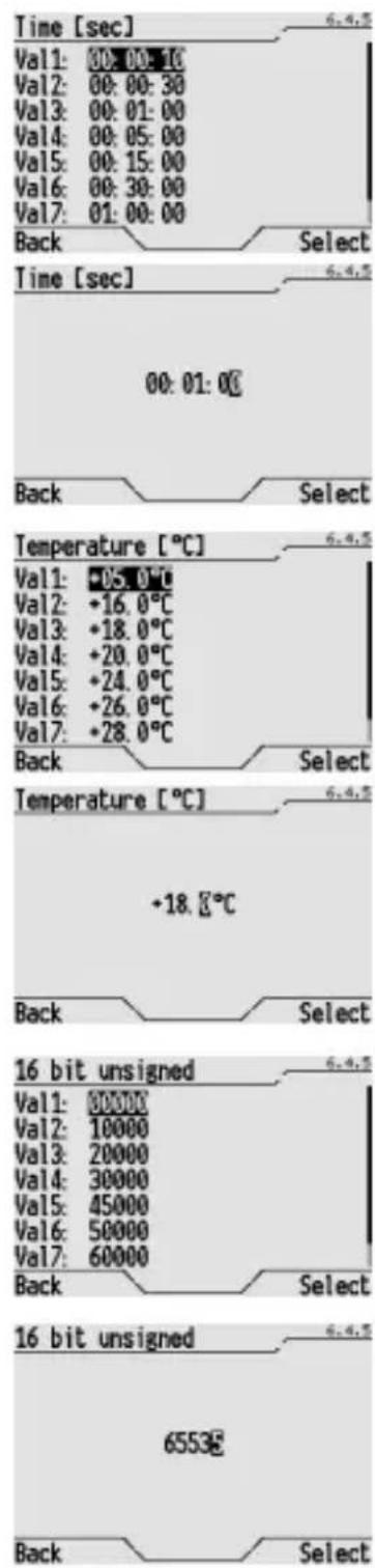
TIME
Use the and buttons to select the value to be edited and press Select to confirm. Use the , , and buttons in the window that opens to enter the time and confirm by pressing Select.
Admitted values: 00:00:00 ÷ 99:59:59.
The value, entered in the window in hour:minutes:seconds format, is sent to the bus expressed in seconds.
TEMPERATURE
Use the and buttons to select the value to be edited and press Select to confirm. Use the , , and buttons in the window that opens to enter the temperature in decrees Celsius and confirm by pressing Select.
Admitted values -99.9 + 99.9
16 BIT VALUES WITHOUT SIGN
Use the and buttons to select the value to be edited and press Select to confirm. Use the , , and buttons in the window that opens to enter the new value and confirm by pressing Select.
Admitted values 0 ÷ 65535 .
ADVANCED FUNCTIONS
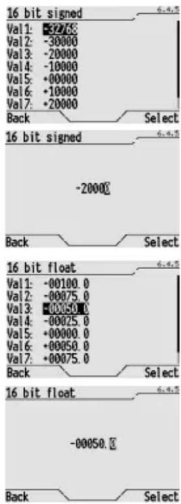
16 BIT VALUES WITH SIGN
Use the and buttons to select the value to be edited and press Select to confirm. Use the , , and buttons in the window that opens to enter the new value, including the sign, and confirm by pressing Select.
Admitted values -32768 ÷ +32767.
16 BIT VALUES FLOATING POINT
Use the and buttons to select the value to be edited and press Select to confirm. Use the , , and buttons in the window that opens to enter the new value, including the sign and decimal points, and confirm by pressing Select.
Admitted values -99999.9 ÷ +99999.9.
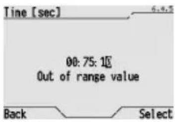
If a value out of the admitted value range is entered in the previously described windows, the "Out of range value" error message temporarily appears.
For example, this screenshot shows the error caused by the value 75 entered in the minutes field which has a maximum value of 59.
Programming a scene sequence
The scene sequence is a scene where the chosen settings are not all activated at the same time, but are activated at intervals according to a preset timed sequence. It is possible to programme up to 16 scene sequences, each of which can manage 16 objects (lights, shutters etc.). Each command can be set for delayed activation from 1 second to 24 hours. All scenes can be created, modified, renamed and cancelled as required.
CREATING A NEW SCENE SEQUENCE
To create a scene sequence, please proceed as follows:
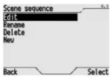
From the Home page, Systems/Rooms Programs Scene sequence.
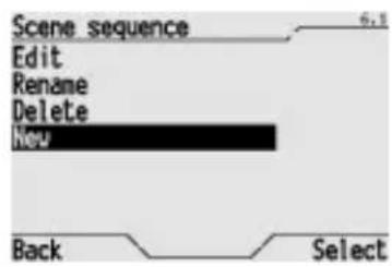
Select New to create a new scene.
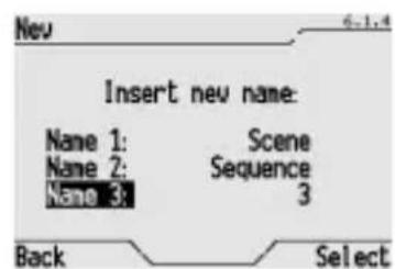
Enter the name of the new scene on the screen. The name is created by selecting 3 different terms from the preset dictionaries (for the terms in the dictionaries, please refer to the Dictionaries section). This name will appear on the screen in the menu and should clearly identify what the scene actually does.
Use the and buttons to move from one dictionary to another, and use the and buttons to scroll terms in the dictionary.
Press Select to confirm the name.
A new window appears where you must enter the commands for the new scene. For further details on how to enter and configure the commands, please refer to the Modifying a scene sequence section.
MODIFYING A SCENE SEQUENCE
To modify a scene sequence, adding or eliminating commands or changing the order in which they are activated, please proceed as follows:

From the Home page, Systems/Rooms Programs Scene sequence.
Select Edit to enter the modification procedure.
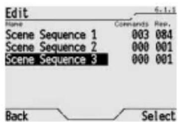
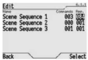
The window displays the complete list of the scene sequences, with the number of commands for each scene, and the number of repetitions set for each activation.
Use the and buttons to select the scene you wish to change, and press Select to confirm.
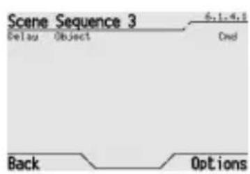
If the scene has no commands the popup on the screen will be empty, on the contrary a list of set commands will be displayed.
The delay set for activating each command on the scene sequence is displayed, the object it refers to and the action it performs.
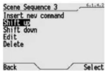
Select Options to view the list of functions available:
- Insert new command, which allows you to queue a new command behind those already entered; if you are creating a new scene, this is the only option available.
- Shift up, which allows you to move the highlighted command up the list; if you need to move it higher than one place, repeat the procedure as necessary.
- Shift down, which allows you to move the highlighted command down the list; if you need to move it lower than one place, repeat the procedure as necessary.
- Delete, which allows you to cancel the highlighted command.
Press Select to confirm the function mode.
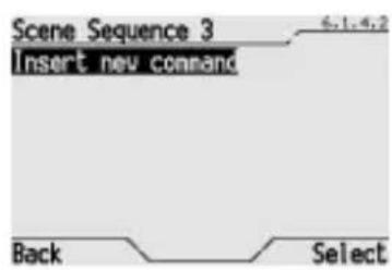
To enter a new command in the scene sequence, select Insert new command.
ADVANCED FUNCTIONS
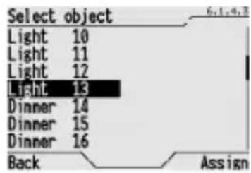
The window on the screen lists all the objects which can be used (scenes, lights, shutters etc.). Select the object you require and press Assign to confirm.
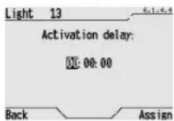
Enter the activation delay time in the window that opens, that is the time that must pass between the time the previous command is activated and the time the new command is activated. Time is entered in hour:minutes:seconds format using the , , and buttons and confirmed by pressing Assign.
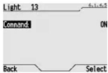
A new window appears where you can set the command that the object must perform. Use the and buttons to select the available commands and press Select to confirm. The commands which are available depend on the type of object. The most common commands are as follows: ON=enable/activate; OFF=disable/deactivate; UP=raise shutter/blind; DOWN=lower shutter/blind; STOP=stop; INC=increases dimmer intensity; DEC=decreases dimmer intensity etc.
NOTE: If available for the selected object, commands can also be values in the corresponding list belonging to the 8 or 16 bit value group or, for shutters with percent control, the list of possible percent values (%) . For further information, please see the Setting 8 and 16 bit values section.
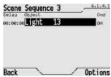
After confirming the new command, a new window appears which lists all the commands of the scene sequence, with the time delays, the objects and the command that is activated; the last command to be entered is the last in the list.
NOTE: For commands belonging to a list of 8 and 16 bit values, "Val1", "Val2", etc. will appear in the "Cmd" column.
To change the command activation sequence, use the and buttons to select the command from the command list and select Options Shift up or Shift down and confirm by pressing Select.
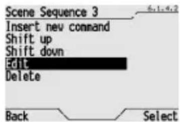
To modify a command, use the and buttons to select the command from the command list and select Edit in the Options menu; press Select to confirm. Then modify, as necessary, the time delay and the command that the object must perform.
ADVANCED FUNCTIONS
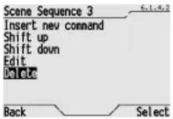
To delete a command, use the and buttons to select the command from the command list and select Delete in the Options menu; press Select to confirm.
MODIFYING THE NUMBER OF REPETITIONS OF A SCENE SEQUENCE
A scene sequence can be repeated automatically for a specific number of times or indefinitely. This means it is possible, for instance, to create presence simulations, control the functions of a water pump to avoid problems caused by icing in the winter and so on. To change the number of times a scene is repeated, please proceed as follows:

From the Home page, Systems/Rooms Programs Scene sequence.
Select Edit to enter the modification procedure and press Select to confirm.
The window displays the complete list of the scene sequences, with the number of repetitions (Rep) set for each activation.
Use the and buttons to select the scene for which you wish to modify the repetitions, use the button to move to the Rep column and press Select to confirm.
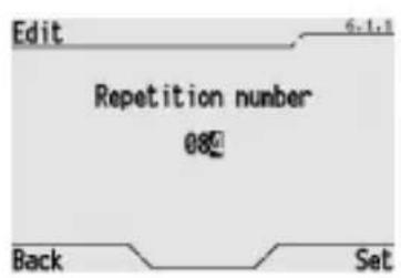
Use the , , and buttons in the window that appears to increase or decrease the number of set repetitions. If this is set to 0, the number of repetitions is infinite (in this case to stop the scene sequence you have to deactivate it manually as indicated in the Activating a scene or a scene sequence section).
Press Set to confirm.
RENAMING A SCENE SEQUENCE
If you wish to rename a scene sequence, for instance to make the name more distinctive or because the name no longer corresponds to the actions foreseen by the scene after modifications, please proceed as follows:
From the Home page, Systems/Rooms > Programs > Scene sequence.
ADVANCED FUNCTIONS
Select Rename to enter the renaming procedure and press Select to confirm.
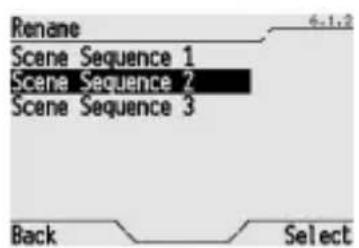
The window that opens lists all the scene sequences. Use the and buttons to select the scene you wish to rename, and press Select to confirm.
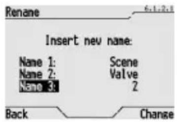
Enter the name of the new scene in the window that opens. The name is created by selecting 3 different terms from the preset dictionaries (for the terms in the dictionaries, please refer to the Dictionaries section).
Use the and buttons to move from one dictionary to another, and use the and buttons to scroll terms in the dictionary.
Press Change to confirm the name.
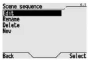
CANCELLING A SCENE SEQUENCE
To cancel a scene sequence, please proceed as follows:
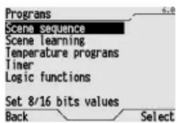
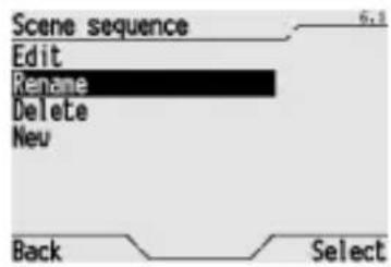
From the Home page, Systems/Rooms Programs Scene sequence.
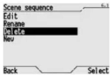
Select Delete and press Select to confirm.
The window that opens lists all the scene sequences. Use the and buttons to select the scene you wish to delete, and press Select to confirm.
The popup message "Object deleted" confirms it has been cancelled.
Programming the thermal regulation system
The control panel can act as the master controller and send the operation type and mode or set point via the bus to the various thermostats and timed-thermostats installed on the system and configured as slave devices.
To programme the operation mode or temperature profile on a weekly basis and the times they must be activated, please proceed as follows:
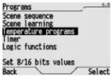
From the Home page, Systems/Rooms Programs Temperature programs.
On the window that appears, use the and buttons to select the function type profile (heating or conditioning) that you need to change and press Select to confirm.
The two heating and air conditioning profiles are managed separately by the control panel. When the season changes, it is therefore sufficient to simply change the function type on the control panel (see the Modifying the thermal regulation section).
The thermostats and timed-thermostats set as slave devices on the system comply to the function type and mode set on the control panel.
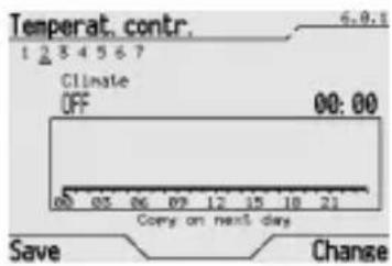
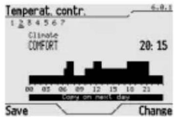
This window shows the profile for the current day, which is underlined. All the information displayed on the screen is illustrated in detail in the section 'Viewing time profiles'.
If you wish to move on to another day, press the button and use the and buttons until the day you wish to modify is highlighted. Press Change to confirm.
Use the and buttons to change from days to hours to Copy on next day, and vice-versa.
Use the and buttons to move the cursor to the hours section; this is regulated 15 minutes at a time and the time is shown in the top right section of the square.
ADVANCED FUNCTIONS
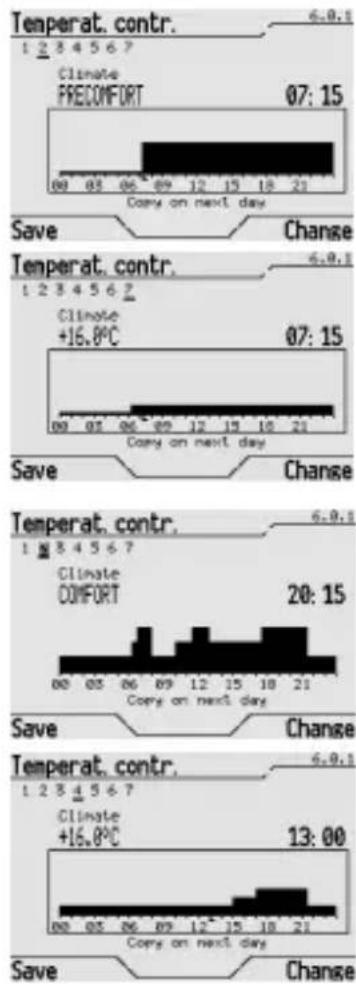
When you reach the time when the change in operation mode should occur, select Change several times until you see the desired mode or set point value highlighted in the left top corner above the square. Mode cyclically changes between OFF, ECONOMY, PRECOMFORT, COMFORT and AUTO, while proposed set points are those in the Temperature ^ C list (see the 8 and 16 bit settings section) and are displayed on the left.
The set mode or set point remain activated until the next change is made, if set, or until the end of the day if there are no other variations. The operation mode or set point is also displayed on the screen in graphic form.
WARNING: in operating mode configuration, the panel sets the mode in the slave timed-thermostats and thermostats and not the temperature (with the same mode, therefore, timed-thermostats and thermostats could manage different room temperatures). In the time range set as AUTO, the control panel will send the slave timed-thermostats the AUTO mode command. The timed-thermostats will hence follow the daily temperature profile memorised in their own database and will also set the function mode for the thermostats in their zone. Contrarily, in set point configuration, the panel sets the same reference temperature in slave timed-thermostats and thermostats, to which they apply a local variation.
To copy the time profile to the next day, press and when Copy on next day is highlighted select Change to copy the same. To copy this profile to all days of the week, select Copy on next day repeatedly until you return to the day you started from. The copied profile can be modified at will following the instructions provided above.
When you have finished programming, select Save to save the changes and return to the Programs menu.
NOTE: when a time profile is enabled with the ENABLE PROG. command, the mode and set point set when the profile was enabled are immediately sent to the bus.
To set the thermal regulation function type, please refer to the Modifying thermal regulation section.
Programming the timers
The control panel can be used to associate weekly (timer) function profiles to various objects (lights, scenes, shutters etc.) to automate repeated actions. For instance it is possible to open or close an awning at a set time to protect the room from the sun, or activate the "wake-up" scene every morning at a set time.
Up to 12 timers can be programmed with 2 value commands (for example ON/OFF, Up/Down etc) and 6 timers that can be 2 values or multilevel with the possibility of selecting commands or values in 8 and 16 bit lists (see the 8 and 16 bit value settings section). It is also possible to use the timers and the scene sequences to create "presence simulations" which can help to reduce burglary risks. All timers can be created, modified, renamed and cancelled as required. The deactivation of a timer does not cancel the associated time profile.
NOTE: when a timer is activated, the communication object associated with the timer is sent to the bus for the first time when the set time profile changes for the first time.
CREATING A NEW TIMER
To create a new timer, please proceed as follows:
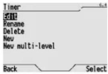
From the Home page, Systems/Rooms Programs Timer.
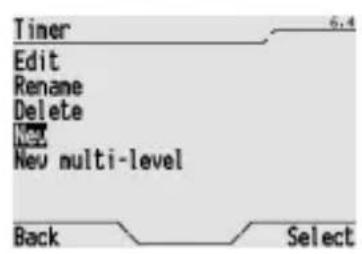
Create the new timer by selecting New for a 2 value timer or New multi-level for a timer with 2 or more levels.
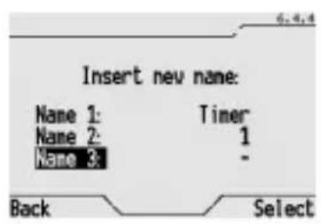
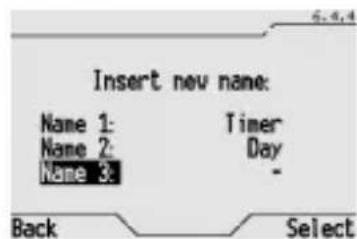
Enter the name of the new timer on the window that appears on the screen. The name is created by selecting 3 different terms from the preset dictionaries (for the terms in the dictionaries, please refer to the Dictionaries section). This name will appear on the screen in the menu and should clearly identify what the timer actually does.
Use the and buttons to move from one dictionary to another, and use the and buttons to scroll terms in the dictionary.
Press Select to confirm the name.
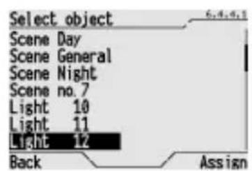
Select the object name of the new timer on the window that appears on the screen and select Assign to confirm.
The time profile will appear on the screen. For further details on how to modify the time profile, please refer to the Modifying a timer section.
ADVANCED FUNCTIONS
MODIFYING A TIMER
To modify the time profile on a timer, that is setting when and what the object related to the timer should do, please proceed as follows:

From the Home page, System/Rooms > Programs > Timer.
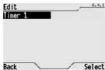
Select Edit to enter the modification procedure.
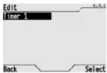
The window that opens lists all the timers. Use the and buttons to select the timer you wish to change, and press Select to confirm.
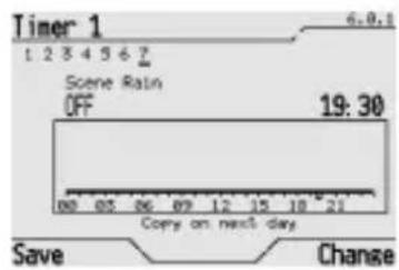
This window shows the profile for the current day, which is underlined. All the information displayed on the screen is illustrated in detail in the section Viewing time profiles. If you wish to move on to another day, press the button and use the and buttons until the day you wish to modify is highlighted. Press Change to confirm. Use the and buttons to change from days to hours to Copy on next day, and vice-versa.
Use the and buttons to move the cursor to the hours section; this is regulated 15 minutes at a time and the time is shown in the top right section of the square.
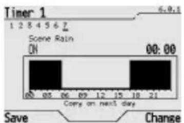
When you reach the time when the change in the object status or value, for multilevel timers, should occur, select Change several times until you see the desired status or value highlighted in the left top corner above the square. The status changes cyclically listing the options available for the object (for instance ON/OFF, UP/DOWN etc.). The set status remains activated until the next change is made, if set, or until the end of the day if there are no other variations.
The profile is also displayed graphically.
ADVANCED FUNCTIONS
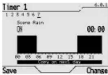
To copy the time profile to the next day, press and when Copy on next day is highlighted select Change to copy the same. To copy this profile to all days of the week, select Copy on next day repeatedly until you return to the day you started from.
The copied profile can be modified at will following the instructions provided above.
When you have finished programming, select Save to save the changes and return to the Programs menu.
To activate a timer, please refer to the Activating a timer section.
RENAMING A TIMER
To rename a timer, please proceed as follows:
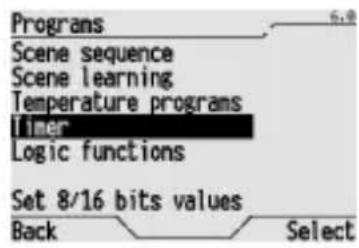
From the Home page, Systems/Rooms Programs Timer.
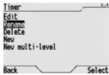
Select Rename and press Select to confirm.
The window that opens lists all the created timers. Use the and buttons to select the timer you wish to rename, and press Select to confirm.
The old name which can be cancelled or modified is displayed on the screen, using 3 different terms from the preset dictionaries (for the terms in the dictionaries, please refer to the Dictionaries section).
Use the and buttons to move from one dictionary to another, and use the and buttons to scroll terms in the dictionary.
Press Select to confirm the name.
ADVANCED FUNCTIONS
CANCELLING A TIMER
WARNING: When a timer is no longer required, it is not always necessary to cancel it, sometimes you can simply deactivate it as illustrated in Activating a timer section. This means you do not lose the settings of the time profile.
To cancel a timer, please proceed as follows:

From the Home page, Systems/Rooms Programs Timer.
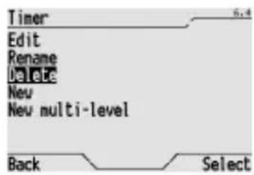
Select Delete and press Select to confirm.
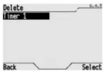
The window that opens lists all the timers. Use the and buttons to select the timer you wish to delete, and press Select to confirm.
The popup message "Object deleted" confirms it has been cancelled.
Programming logic functions
The control panel can also be used to associate logic functions to various objects. By using the logic functions it is possible to create conditioned actuations, that is actuations that depend on the status of 1, 2, 3 or 4 inputs. For instance you can logically connect two lights so that they are never on at the same time, or set the awnings to close where there is too much wind. It is possible to create up to 16 logic functions.
CREATING A LOGIC FUNCTION
To create a new logic function, please proceed as follows:
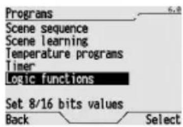
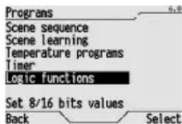
From the Home page, Systems/Rooms Programs Logic functions.
Select New to create a new function.
ADVANCED FUNCTIONS
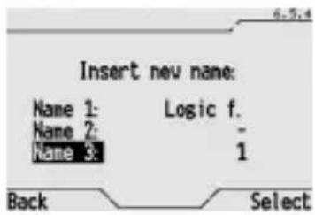

Enter the name of the new logic function on the screen. The name is created by selecting 3 different terms from the preset dictionaries (for the terms in the dictionaries, please refer to the Dictionaries section). This name will appear on the screen in the menu and should clearly identify what the logic function actually does.
Use the and buttons to move from one dictionary to another, and use the and buttons to scroll terms in the dictionary.
Press Select to confirm the name.
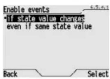
When the window opens, it is possible to set the mode in which the events should be enabled, according to whether the logic result is TRUE or FALSE). Use the and buttons to select the item:
- "if state value changes" the commands associated to the TRUE and FALSE events will only be performed when the result of the logic function changes (from FALSE to TRUE or from TRUE to FALSE);
- "even if same state value" the commands associated to the TRUE and FALSE events will be performed each time the bus receives a new input value from the logic function, even if the result (TRUE or FALSE) does not change.
Press Select to confirm.
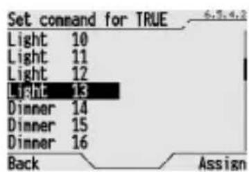
When the window opens, select the object on which the command should be performed if the result of the logic operation is TRUE and select Assign to confirm.
When the window opens, select the command that should be performed on the previously selected object if the result of the logic operation is TRUE, using the and buttons and choose Select to confirm. The commands available all relate to the specific object (for instance ON/OFF for a light, UP/DOWN/STOP for a shutter) or the values belonging to the list of the selected object.
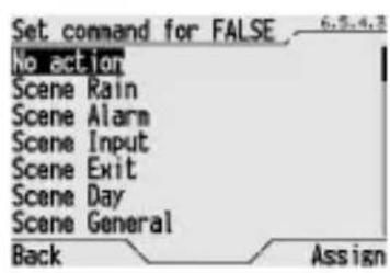
When the window opens, select the object on which the command should be performed if the result of the logic operation is FALSE and select Assign to confirm. The objects selected for the TRUE and FALSE results can be different.
When the window opens, select the command that should be performed on the previously selected object (if the result of the logic operation is FALSE), using the and buttons and choose Select to confirm. The commands available all relate to the specific object (for instance ON/OFF for a light, UP/DOWN/STOP for a shutter) or the values belonging to the list of the selected object. If the "No action" option is selected for a TRUE event or FALSE event, it is not necessary to select a command.
Audible alarm on logic functions
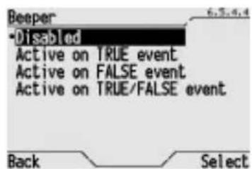
It is possible to associate an audible alarm to a logic function generated by the control and display panel buzzer. When the page opens it is possible to select:
- Disabled, that never enables the audible alarm.
- Active on TRUE event, which activates the audible alarm for a max of 5 minutes when the event is true.
Active on FALSE event, which activates the audible alarm for a max of 5 minutes when the event is false.
Active on TRUE/FALSE event, which activates the audible alarm for a max of 5 minutes whether the event is true or false.
The audible alarm is signalled on the Home page with icon [s]To disable the audible alarm, use the and arrows to move to this icon and press the or button. The logic functions page opens where you can check which function generated the alarm and cancel the alarm memory as described in the Enable disable a logic function section.
ADVANCED FUNCTIONS
NOTE: it is possible to define a logic function with 1 input only, and associate the "No action" option for a true event or a false event. An audible alarm can still be associated with this logic function. This way, an audible alarm can be generated for an input status.
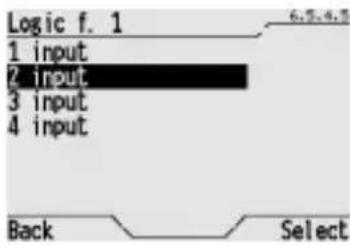
In this window select the number of inputs required to perform the desired function and press Select to confirm.
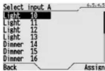
The window that opens lists all the available objects. Use the and buttons to select the object which corresponds to the first input (input A) and press Assign to confirm.
Repeat this procedure for all the other inputs (the objects already used will automatically be excluded from the list).
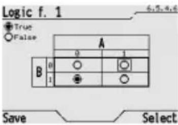
At the end the window will display the possible combinations among the selected inputs. When the function is created, the result of each combination of inputs is FALSE.
It is now possible to customise the logic function and assign a TRUE or FALSE result to each possible combination of the input statuses.
To make the result of a combination of inputs TRUE, use the , , and buttons to move to the field that represents the combination and change the logic result of the combination by pressing Select.
An empty circle indicates that the result is FALSE, a full circle indicates that the result is TRUE.
When the whole table shows all the logic results that you wish to associate to the various combinations of the input statuses, press Save to save the results.
To activate a logic function, please refer to the "Activating a logic function" section.
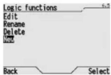
MODIFYING A LOGIC FUNCTION
To modify a logic function, for instance to add inputs, modify the commands or the function layout, please proceed as follows:
From the Home page, Systems/Rooms > Programs > Logic functions.
ADVANCED FUNCTIONS
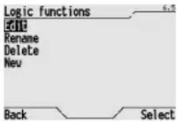
Select Edit to modify a logic function and press Select to confirm.
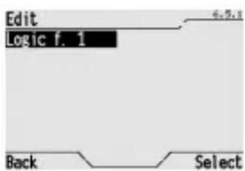
The window that opens lists all the logic functions. Select the function you want to modify and press Select to confirm.
The various programming windows described in the Creating a logic function section are proposed in sequence on the screen. The currently set value is indicated in each window, which can be confirmed or modified at will.
RENAMING A LOGIC FUNCTION
To rename a logic function, please proceed as follows:

From the Home page, Systems/Rooms > Programs > Logic functions.
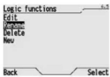
Select Rename to rename a logic function and press Select to confirm.

The window that opens lists all the logic functions. Select the function you want to rename and press Select to confirm.
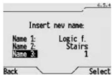
The old name which can be cancelled or modified is displayed on the screen, using 3 different terms from the preset dictionaries (for the terms in the dictionaries, please refer to the Dictionaries section).
Use the and buttons to move from one dictionary to another, and use the and buttons to scroll terms in the dictionary.
Press Select to confirm the name.
CANCELLING A LOGIC FUNCTION
To cancel a logic function, please proceed as follows:
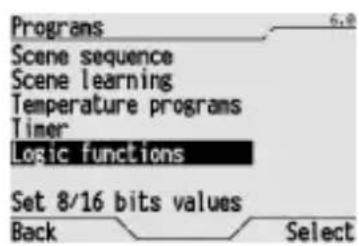
From the Home page, Systems/Rooms > Programs > Logic functions.
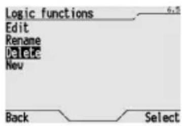
Select Delete to delete a logic function and press Select to confirm.
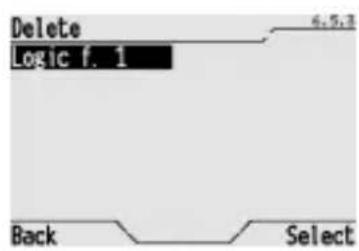
The window that opens lists all the logic functions. Select the function you want to delete and press Select to confirm.
The popup message "Object deleted" confirms it has been cancelled.
Dictionaries
DEFAULT WORD LIST
The control panel has five term dictionaries that are used when you need to name rooms, systems, functions, scenes etc. The maximum length of the words in each dictionary is specified and each dictionary contains a group of default vocabulary, as seen in the chart below.
| DICTIONARY | MAX CHARACTERS | DEFAULT WORD LIST |
| Dictionary 1 | 10 | <null>, Actuator, Dimmer, Relay, Light, Lamp, Shelter, Curtain, Louvres, Window, Function, Control Command, State, Switch, Rocker, Contact, Sensor, Detector, Alarm, Block, Priority, Scene, Input, Output, Enable, Disable, Heating, Cooling, Time, Delay, On, Off, Economy, Precomfort, Comfort, Auto, Valve, Irrig., Activat., Deactiv., General, Total, Partial, Zone, Room, Climate, Module, Value, Intensity, Temp., Brightness, Logic f., Voltage, Current, Power, Mode, Setpoint, Object, Timedtherm Thermostat, BurglarSys, Timer, Clock, Unit, Setting, Ringbell. |
| Dictionary 2 | 8 | <null>, Actuat., Dimmer, Relay, Light, Lamp, Shelter, Curtain, Louvres, Window, Function, Control Command, State, Switch, Rocker, Contact, Sensor, Detector, Alarm, Block, Prior., Scene, Input, Output, Enable, Disable, Heating, Cooling, Time, Delay, On, Off, Economy, Precomf., Comfort, Auto, Valve, Sequence, Irrig., Activation, Deactivation, General, Total, Partial, Zone, Room, Water, Gas, Wind, Rain, Smoke, Twilight, Plug, Presence, Move, Door, Pos., Pos. %, Battery, Master, Central, Left, Right, Above, Under, Up, Down, Slope, Descent, Exterior, Interior, Entrance, Exit, Anter., Bathroom, Balcony, Boiler, Cellar, Kitchen, Garage, Garden, Laundry, Mansard, Floor, Sit room, Living, GreenH., Studio, Tavern, Terrace, Office, Parents, Children, Guest, Day, Night, Big, Little, Nord, Sud, West, East, 1, 2, 3, 4, 5, 6, 7, 8, 9, 10, 11, 12, 13, 14, 15, 16, 17, 18, On/Off, Up/Down, Hea/Cool, Logic, Timer, Stairs. |
| Dictionary 3 | 1 | 1, 2, 3, 4, 5, 6, 7, 8, 9, 0, A, B, C, D, E, F, G, H, I, J, K, L, M, N, 0, % |
| Rooms | 13 | Hide, Anteroom, Hall, Bathroom, Balcony, Boiler, Room, Cellar, Passage, Kitchen, Outdoor, Garage, Garden, Guard, Entrance, Indoor, Laundry, Serv. room, Mansard, Lodge, Reception, Storage, Sit room, Living, GreenH., Liv ROOM, Studio, Tavern, Terrace, Office, Veranda, Room 1, Room 2, Room 3, Room 4, Underground, Low ground, Floor 1, Floor 2. |
| Systems | 13 | Hide, Access, Auxiliary, Automatism, Loads, Meteo Unit, Switchboard, Cooling, Meter, Dimmer, Emergency, Fan Coil, Inputs, Lighting, Irrigation, Lights, Measures, Detectors, Heating, Sensors, Shutters, Curtains, Climate, Thermostat, Output, Contr. Plug. |
ADVANCED FUNCTIONS
ADDING A WORD
Users can add new words of their choice to the existing dictionaries, respecting the maximum number of characters per word of each dictionary (see previous table).
The maximum number of new words that can be added to the individual dictionaries is:
Dictionary 1:70
Dictionary 2:10
Dictionary 3:10
Rooms: 20
Systems: 30
NOTE: When a dictionary reaches the maximum number of new words allowed, the Add to wordlist menu item is no longer displayed for that dictionary.
To add a new word to a dictionary, please proceed as follows:
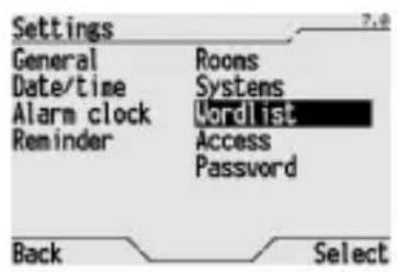
From the Home page, Systems/Rooms Settings Wordlist.
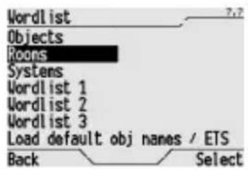
The dictionaries available are listed. Select the dictionary you wish to add a new word to and press Select to confirm.
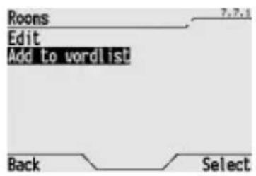
In the window that appears, select Add to wordlist and press Select to confirm.
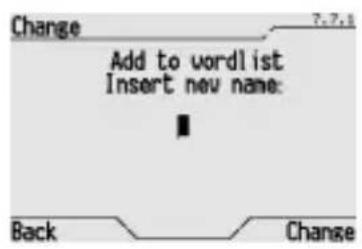
Now enter the new word. For further information on how to enter letters and numbers, please refer to the Entering text section.
Press Change to confirm the addition of the new word.
MODIFYING A WORD
To modify a new word added to a dictionary, please proceed as follows:
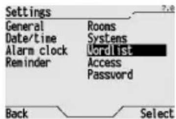
From the Home page, Systems/Rooms > Settings > Wordlist.
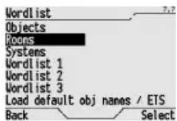
The dictionaries available are listed. Select the dictionary that contains the word you wish to modify and press Select to confirm.
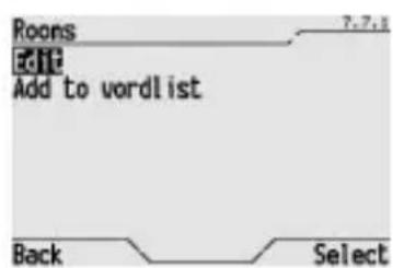
In the window that appears, select Edit and press Select to confirm.
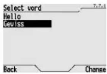
Use the and buttons to select the word you wish to modify from the list, and press Change to confirm.
WARNING: only the words you have added to the dictionary will be listed, it is not possible to modify default vocabulary.
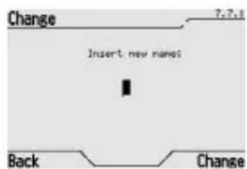
Change the word. For further information on how to enter letters and numbers, please refer to the Entering text section.
Press Change to confirm the modified word.
NOTE: words cannot be cancelled but if the maximum number of words is exceeded for a certain dictionary, an existent added word must be modified.
INSTALLATION

WARNING: the installation of the device must be exclusively done by qualified personnel, following the regulations in force and the guidelines for KNX/EIB installations.
Warnings for KNX/EIB installations
- The length of the bus line between the EIB control panel and display and the power supply unit must not exceed 350 metres.
- The length of the bus line between the EIB control panel and display and the most distant KNX/EIB device must not exceed 700 metres.
- If possible do not create ring circuits so as to prevent undesirable signals and overloads.
- Keep a distance of at least 4mm between the individually insulated cables of the bus line and those of the electric line.
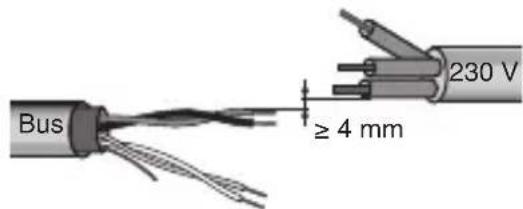
- Do not damage the electrical continuity conductor of the shielding.
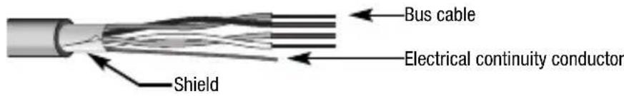
WARNING: the unused bus signal cables and the electric continuity cable must never touch powered elements or the grounding cable!
Electrical connections
WARNING: disconnect the network voltage before connecting the device to the power network!

Electrical connections diagram
INSTALLATION
- Connect the bus cable's red wire to the terminal's red connector (+) and the black wire to the black connector (-). Up to 4 bus lines (wires of the same colour in the same connector) can be connected to the bus terminal.
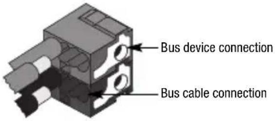
- Insulate the screen, the electrical continuity conductor and the remaining white and yellow wires of the bus cable (should a bus cable with 4 conductors be used), which are not needed.
- Insert the bus clamp into the relative device terminal.
The fastener guides determine the direction it should be inserted.
- Close the bus clamp housing with the cover supplied.
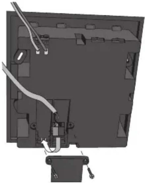
- Connect the mains power (230V) to the control panel using the two terminals marked L and N.
Completing installation
- Fasten the control panel to the flush-mount unit GW 24 237 using the 4 screws supplied.
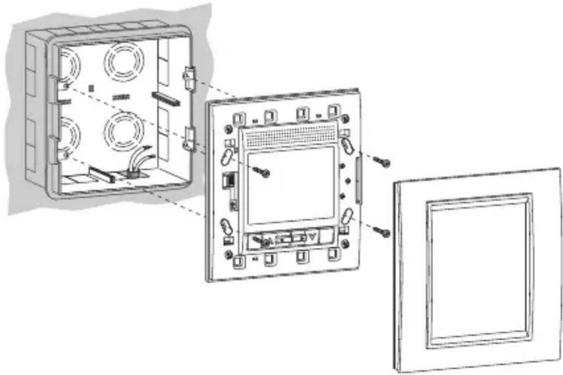
- Use a little pressure to apply the cover. A click indicates that it is securely fastened.
USB Port
Under the cover plate, to the left of the display, you will find the USB (1) mini port and the potentiometer to regulate the contrast on the display screen (2).
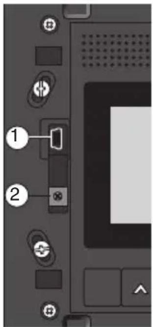
It is possible to connect the control panel to a PC using the USB port and, using the relative software it is possible to perform the functions listed below:
- Create a backup copy of the control panel settings (timer programmes, thermal regulation system settings, scene sequences, words added to the dictionaries etc.).
- Reload the previously saved settings onto the control panel.
- Copy the settings onto another control panel. It is only possible to copy the settings to another control panel if the communication objects have been configured in the same order on the bus as the original control panel.
For further information on the programming software functions, or to download the software, please visit the website www.gewiss.com and go to the EIB Control Panel and display page (GW12789TB, GW12789VT, GW12789VA).
CONFIGURATION
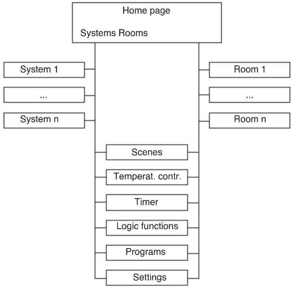
Menu tree
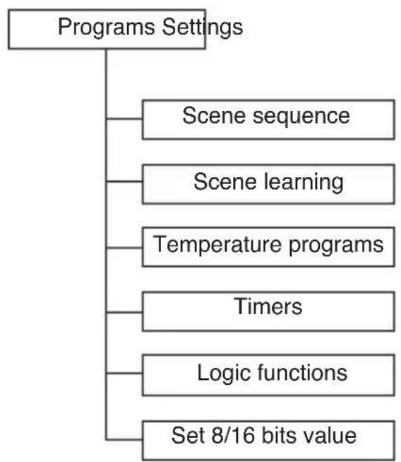
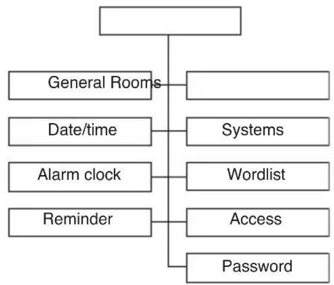
CONFIGURATION
General settings
The language used for the menus, the temperature scale and other elements on the control panel are part of the general settings and can be customised by the user.
The general default settings on the control panel are as follows:
| Language | Italian |
| Temperature reading | Degrees centigrade |
| Backlight | 100% |
| Beeper | Disabled |
| Homepage Timeout | Disabled |
To change the default settings, please proceed as follows:
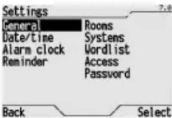
From the Home page, Systems/Rooms > Settings > General.
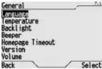
The list of parameters which can be modified is displayed.
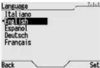
To change the language used in the menu, select Language and then the language you wish to use from the list (the current language used has a dot beside it). Press Set to confirm.
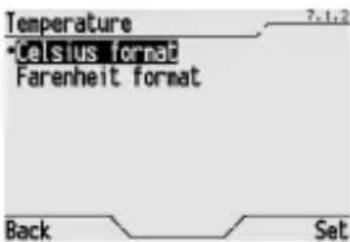
To change the temperature scale used, select Temperature and then the Celsius format or Fahrenheit format (the current format used has a dot beside it). Press Set to confirm.
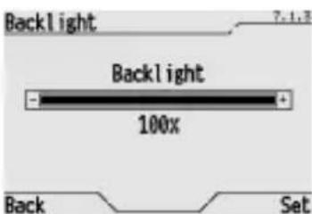
To change the luminosity level on the display screen, select Backlight and change the percentage value using the and buttons. Press Set to confirm the new setting.
If necessary, you can also change the contrast on the screen using the relative potentiometer. Please refer to the USB port section for information on where to find the contrast potentiometer
CONFIGURATION
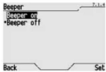
To enable or disable the beeper when the buttons are pressed select Beeper and then Beeper on or Beeper off (the current setting used has a dot beside it). Press Set to confirm.
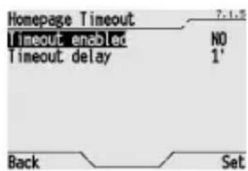
To enable or disable the time out (automatic return to the Home page after a specific period of time has passed since a button was last pressed) select Homepage Timeout. Use the and buttons in the page that opens to move from Timeout enabled to Timeout delay, and vice versa, and the and buttons to change the set value. The timeout duration can vary from 30 seconds to 15 minutes. Press Set to confirm.
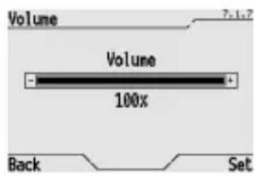
To change the volume of the sound signals on the control panel, select Volume and change the percentage value using the and buttons. Press Set to confirm the new volume.
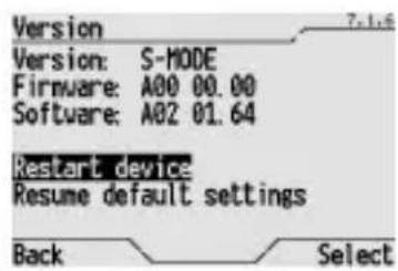
To find out the firmware and software versions used by the control panel, select Version. Select Back to exit the page.
Setting the time and date
Set the time and the date on the control panel as illustrated in the Regulating the time and Regulating the date sections to make sure the daily and weekly profiles on the thermal regulation and timers all function properly.
CONFIGURATION
Assigning names to communication objects
A name can be assigned to each communication object via ETS. This operation is performed at the same time the panel is installed: when the panel is in factory settings, names are assigned to objects. In any case, the name assigned during ETS configuration can always be replaced with another name with a local operation. The name entered locally takes priority over names downloaded via ETS. Subsequent ETS configurations do not cancel locally assigned object names: to make the new name downloaded via ETS visible, see the Assigning names downloaded from ETS section.
NOTE: If an empty name is selected in the ETS download, the panel automatically assigns default names.
Renaming objects and scenes
It is possible to change the name using the words in the 3 dictionaries, 1, 2 and 3, or create a new name by adding a word to the relative dictionaries. For further information on the dictionaries, please refer to the Dictionaries section.
To change the name automatically assigned via ETS to an object or a scene, please proceed as follows:

From the Home page, Systems/Rooms > Settings > Wordlist > Objects.
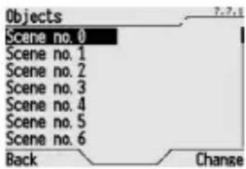
Use the buttons to select the object you wish to rename, and press Change to confirm.
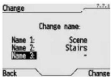
The old name which can be cancelled or modified is displayed on the screen, using 3 different terms from the preset dictionaries (for the terms in the dictionaries, please refer to the Dictionaries section).
Use the and buttons to move from one dictionary to another, and use the and buttons to scroll terms in the dictionary.
Press Change to confirm the name.
ATTRIBUTION OF THE NAMES DOWNLOADED FROM ETS.
If the names downloaded from ETS have not been modified locally, they will be assigned automatically to the objects during each download.
To assign the name downloaded from ETS or the one assigned by default to replace a name assigned locally, please proceed as follows:
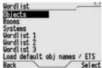
From the Home page, Systems/Rooms > Settings > Wordlist > Objects.
CONFIGURATION
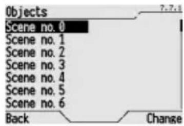
The various objects are listed. Select the object you wish to rename, and press Change to confirm.
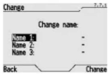
The name assigned locally is displayed on the screen. Scroll the words in the 3 dictionaries and assign " - " to Name 1, Name 2 and Name 3. Press Change to confirm. The object will be assigned the name downloaded from ETS (or the default name if no name was selected via ETS).
To replace all the names memorised locally with those downloaded via ETS (or the default name if no name was selected via ETS), please proceed as follows:
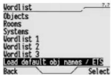
From the Home page, Systems/Rooms Settings Wordlist.
Select Load default obj names / ETS object names and press Select to confirm.
Names of the rooms
The control panel has the Room dictionary stored in its memory and this contains the most common words that identify the various types of rooms. If the required name is not included in the default dictionary, it is possible to add it as explained in the Dictionary section.
Names of the systems
The control panel has the Systems dictionary stored in its memory and this contains the most common words that identify the various types of systems. If the required name is not included in the default dictionary, it is possible to add it as explained in the Dictionary section.
CONFIGURATION
Assigning objects to rooms
To assign various objects to specific rooms, please proceed as follows:
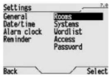
From the Home page, Systems/Rooms Settings Rooms.

Select the room you wish to assign the objects to from the list and press Select to confirm.
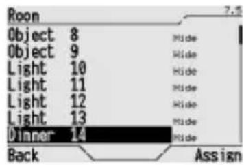
Select the objects that you want to assign to the selected room and press Assign to confirm. When an object is assigned, the name of the room it is assigned to appears at its side. Hide means the object has not been assigned to any room.
If you wish to exclude an object from a room, select Hide in the room list and then assign the object to be excluded to this nonexistent room.
Assigning objects to systems
After setting the panel with ETS, each object is automatically assigned to the corresponding logic system based on the function assigned via ETS to the block the object belongs to, as shown in the following table.
| Function associated with the object block System | |
| Dimmer; command 2 relay outputs; command 1 relay output + override Lighting | |
| Shutters Shutters | |
| Base burglar alarm, partial burglar alarm arming Burglar alarm | |
| Master thermal regulation; display thermal regulation Climate control | |
| Independent objects (scene) Scenes | |
| Independent objects (override or output objects) Outputs | |
| Independent objects (input objects) Inputs |
It is in any case possible to assign objects to any system following the procedure below:
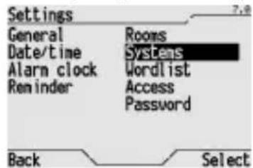
From the Home page, Systems/Rooms Settings Systems.
CONFIGURATION
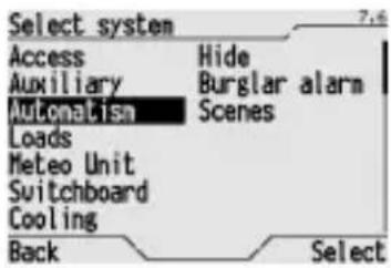
Select the system you wish to assign the objects to from the list and press Select to confirm.
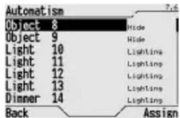
Select the objects that you want to assign to the selected system and press Assign to confirm. When an object is assigned, the name of the system it is assigned to appears at its side. Hide means the object has not been assigned to any room.
If you wish to exclude an object from a system, select Hide in the system list and then assign the object to be excluded to this nonexistent room.
View
To change the view mode of the control panel Home page, that is to view only the item to access the systems, or only the item to access room, or both view modes, please proceed as follows:
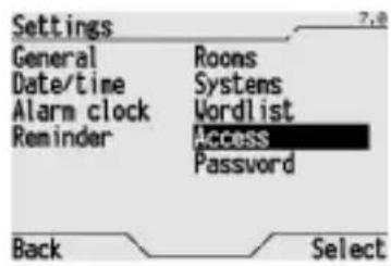
From the Home page, Systems/Rooms Settings Access.
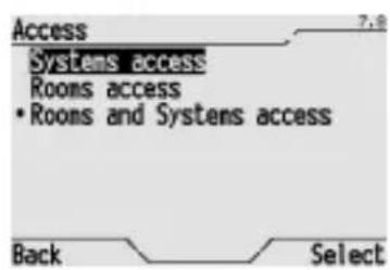
Select from Systems access, Rooms access or Rooms and Systems access and press Select to confirm (the current option is indicated with a dot).
Behaviour on the failure and reinstatement of the bus power supply
When there is no bus voltage, the control panel will remain on, but it is not possible to perform commands addressed to devices connected to the bus. The device is in full operating mode after around 30 seconds from reinstatement of the bus power supply. Based on the ETS configuration, the panel may or may not require status or input values to be updated for each block. The update may require an additional 30 seconds in the worst case.
If there is no mains power connected to the control panel, it is no possible to perform any procedures. The time and date are maintained by the buffer power system (battery) whilst the settings are saved to a non-volatile memory. The control panel can be used again after 30 seconds from reinstatement of the power supply
If there is no power supply, and the buffer battery is charged, the date and time are maintained for 72 hours. When this time has elapsed, it is necessary to set the time and date again.
Cleaning the control panel
Use a dry cloth to clean the control panel.
Changing the battery
WARNING: disconnect the network voltage before replacing the buffer battery!
To replace the buffer battery:
- remove the finish plate.
- unscrew the four screws and remove flush-mount unit cover;
- disconnect the power supply and the bus power supply;
- remove the bottom of the device by unscrewing the 4 front fastener screws;
- remove the old battery using a screwdriver;
- insert a new battery (rechargeable ML1220 3 V battery), making sure the poles are facing the right way;
- reclose, reconnect and replace the covers following the above instructions in the reverse order.

WARNING:
- only installation operators are allowed to change the batteries;
- never throw the battery into a fire.

The battery is a special waste product and therefore it must be disposed of according to the laws in force and taken to a special collection centre.
Reset
RESETTING THE CONTROL PANEL
Select Restart device (from the Home page, Systems/Rooms Settings General Version) to reset all settings on the control panel. All the settings will remain stored in the memory and the control panel will start to function again after a maximum of 15 seconds.
RESUME DEFAULT SETTINGS
Select Resume default settings (from the Home page, Systems/Rooms Settings General Version) to reset all settings on the control panel. The Resume default settings can not be reversed.

WARNING: you will lose all the settings when you use this option (words added to the dictionaries, locally set wordlists, timer programmes, scenes, scene sequences and logic functions, thermal regulation profiles, burglar alarm, event reminder, wakeup system settings etc.)!
TECHNICAL SPECIFICATIONS
Communication KNX/EIB Bus
Power supply 230V ac
KNX/EIB Bus, 29 V dc SELV
rechargeable battery type ML1220 3 V to update
date and time in the event of black out
Bus cable KNX/EIB TP1
Bus current consumption 1.5mA
Power consumption 2 W
Control elements 1 mini programming key
4 navigation buttons
2 function buttons
1 potentiometer to adjust display contrast
Display elements 1 2.8" backlit monochrome display
1 red programming LED
Detection elements 1 temperature sensor, measurement interval 0 ÷ +40^ C
with 0.1^ resolution
Access protection 1 max. 5 character alphanumeric password
Ambit of use Indoors, dry places
Operating temperature 0 ÷ +40^ C
Storage temperature -20 ÷ +70 °C
Relative humidity Max 93% (no condensation)
Bus connection Slot in terminal, 2 pin 1 mm
Electrical connections Screw terminals, max cable width: 2.5mm
2
Protection rating
IP20
Dimensions (L x H x W)
150 × 158 × 58 (17 from the edge of the wall) mm
Reference standards Low Voltage Directive 2006/95/EC
Electromagnetic compatibility directive 2004/108/EC EN50090, EN60950
Certification
KNX/EIB
SOMMAIRE
SOMMAIRE 136
AVENTISSEMENTS GENERAUX 138
Contenu de la confection 138
DESCRIPTION GENERALE 139
Enbref 139
VALEURS 16 BIT FLOATING POINT
Communication Bus KNX/EIB
Alimentation 230 V ca
bus KNX/EIB, 29 V cc SELV
Cable bus KNX/EIB TP1
VALORES 16 BIT FLOATING POINT
bus KNX/EIB, 29 V cc SELV
Cable bus KNX/EIB TP1
WERTE 16 BIT FLOATING POINT
According to article 9 paragraph 2 of the European Directive 2004/108/EC and to article R2 paragraph 6 of the Decision 768/2008/EC, the responsible for placing the apparatus on the Community market is:
GEWISS S.p.A Via A. Volta, 1-24069 Cenate Sotto (BG) Italy Tel: +39 035 946 111 Fax: +39 035 945 270 E-mail: qualitymarks@gewiss.com


+39 035 946 111
8.30-12.30/14.00-18.00
lunedi ÷ venerdi - monday ÷ friday

+39 035 946 260

sat@gewiss.com
www.gewiss.com

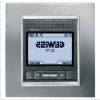
- SAFETY 79
- BASIC FUNCTIONS 80
- CONTENTS
- ADVANCED FUNCTIONS 99
- INSTALLATION 122
- CONFIGURATION 125
- IN SERVICE 132
- TECHNICAL SPECIFICATIONS 133
- GENERAL INFORMATION
- Pack content
- Summary
- Dimmer management
- Shutter/blind control:
- Actuator control
- relay actuator control
- Independent objects for:
- Burglar alarm system control (block 1)
- Burglar alarm system control (block 2)
- Date and time control (block 11)
- Thermal regulation control (block 12)
- Thermal regulation control (block 13)
- Operating principle
- Commands and display
- COMMANDS
- HOME PAGE
- ICONS
- CURSOR
- VIEWING DEVICE STATUS
- VIEWING PERCENT VALUES
- VIEWING TIME PROFILES (THERMAL REGULATION AND TIMER)
- BACKLIGHTING
- ENTERING TEXT
- SECURITY
- Password
- SETTING/MODIFYING THE PASSWORD
- Regulating the time
- Regulating the date
- BASIC FUNCTIONS
- Wakeup alarm
- CREATING OR CHANGING THE WAKEUP ALARM
- DISABLING THE WAKEUP ALARM
- REINSTATING THE WAKEUP ALARM
- Event reminder
- CREATING AN EVENT REMINDER
- DISABLING THE ACOUSTIC SIGNAL
- VIEWING AND MODIFYING AN EVENT REMINDER
- CANCELLING AN EVENT REMINDER
- Switching a light ON and OFF
- Adjusting and switching a dimmer light ON and OFF
- DIMMER LIGHT WITH INCREASE-DECREASE COMMAND
- DIMMER LIGHT WITH PERCENT VALUE COMMAND
- Opening, closing and regulating shutters and blinds
- SHUTTER WITH UP-DOWN COMMAND
- SHUTTER WITH PERCENT VALUE COMMAND
- Priority controls and blocks
- FORCING A LIGHT
- FORCING A SHUTTER OR BLIND
- BLOCKING A SHUTTER OR BLIND
- Inputs
- Outputs
- SELECTION MODE AND DATA ENTRY
- Activation of a scene or a scene sequence
- Modifying the thermal regulation
- Activating and deactivating a timer
- Activating and deactivating a logic function
- Burglar alarm system
- COMPLETE ARMING OF THE BURGLAR ALARM SYSTEM
- PARTIAL ARMING OF THE BURGLAR ALARM SYSTEM
- COMPLETE DISARMING OF THE BURGLAR ALARM SYSTEM
- ADVANCED FUNCTIONS
- Scene
- ASSIGNING A SCENE TO THE SCENE SYSTEM
- CANCELLING A SCENE FROM THE SCENE SYSTEM
- LEARNING A SCENE
- Setting 8 and 16 bit values
- DEFAULT VALUES
- EDITING 8 AND 16 BIT VALUES
- TIME
- TEMPERATURE
- BIT VALUES WITHOUT SIGN
- Programming a scene sequence
- CREATING A NEW SCENE SEQUENCE
- MODIFYING A SCENE SEQUENCE
- MODIFYING THE NUMBER OF REPETITIONS OF A SCENE SEQUENCE
- RENAMING A SCENE SEQUENCE
- CANCELLING A SCENE SEQUENCE
- Programming the thermal regulation system
- Programming the timers
- CREATING A NEW TIMER
- MODIFYING A TIMER
- RENAMING A TIMER
- CANCELLING A TIMER
- Programming logic functions
- CREATING A LOGIC FUNCTION
- Audible alarm on logic functions
- MODIFYING A LOGIC FUNCTION
- RENAMING A LOGIC FUNCTION
- CANCELLING A LOGIC FUNCTION
- Dictionaries
- DEFAULT WORD LIST
- ADDING A WORD
- MODIFYING A WORD
- INSTALLATION
- Warnings for KNX/EIB installations
- Electrical connections
- Completing installation
- USB Port
- CONFIGURATION
- General settings
- Setting the time and date
- Assigning names to communication objects
- Renaming objects and scenes
- ATTRIBUTION OF THE NAMES DOWNLOADED FROM ETS.
- Names of the rooms
- Names of the systems
- Assigning objects to rooms
- Assigning objects to systems
- View
- Behaviour on the failure and reinstatement of the bus power supply
- Cleaning the control panel
- Changing the battery
- WARNING: disconnect the network voltage before replacing the buffer battery!
- WARNING:
- Reset
- RESETTING THE CONTROL PANEL
- RESUME DEFAULT SETTINGS
- TECHNICAL SPECIFICATIONS
- SOMMAIRE
- SOMMAIRE 136
- AVENTISSEMENTS GENERAUX 138
- DESCRIPTION GENERALE 139
- VALEURS 16 BIT FLOATING POINT
- VALORES 16 BIT FLOATING POINT
- WERTE 16 BIT FLOATING POINT
Brand : Gewiss
Model : GW12789VT
Category : Alarm Clock