
GW10861 - Motion detector Gewiss - Free user manual and instructions
Find the device manual for free GW10861 Gewiss in PDF.
| Product Type | Passive infrared (PIR) motion detector |
| Brand | Gewiss |
| Model | GW10861 (GW 10/12/14 861) |
| Power supply | 3 AAA alkaline batteries 1.5 V |
| Battery life | Approximately 2.5 years (with indicators disabled) |
| Radio range | 50 m in open field |
| Detection range | 15 m, 81° opening, 18 zones on 4 levels |
| Coverage type | Volumetric |
| Transmission frequency | LPD (Low Power Device) |
| Alarm integration | Selectable: 2 or 4 pulses in 8 seconds |
| Post-alarm delay | 5 minutes (inhibition) |
| Walk-test mode | 10 minutes with flashing LED |
| Anti-tamper protection | Detector and plate tamper (magnetic contact) |
| Operating temperature | -10 °C to +45 °C |
| Dimensions (ONE plate) | 118 x 90 x 40 mm (L x H x D) |
| Dimensions (LUX plate) | 123 x 90 x 40 mm (L x H x D) |
| Protection rating | IP3X |
| Panel compatibility | GW 20 470, GW 20 481, GW 10 931 |
| Main functions | Infrared presence detection, coded radio transmission, detachable LED indicators |
| Maintenance | Periodic check of operation and batteries |
| Safety | Complies with directives 89/336/EEC and 93/68/EEC |
| Spare parts | AAA alkaline batteries, plate magnet kit |
Frequently Asked Questions - GW10861 Gewiss
User questions about GW10861 Gewiss
0 question about this device. Answer the ones you know or ask your own.
Ask a new question about this device
Download the instructions for your Motion detector in PDF format for free! Find your manual GW10861 - Gewiss and take your electronic device back in hand. On this page are published all the documents necessary for the use of your device. GW10861 by Gewiss.
USER MANUAL GW10861 Gewiss
MANUALE D'USO ANTINTRUSIONE
USER MANUAL:BURGLAR ALARM SYSTEM
Wall-mounted infrared ray volumetric presence detector
NOTICE D'UTILISATION ANTI-INTRUSION
ON: 4 impulsi in 8 seconds
DIP switch 4: ESCLUSIONE ALLARME ASPORTAZIONE RIVELATORE
Wall-mounted infrared ray volumetric presence detector
WARNING
FOR THE INSTALLER:
Carefully follow all operating regulations applicable to the installing of electrical and security system, further to the specifications supplied by the manufacturer in the instruction manual which comes with the products.
Provide the operators with all the instructions for use and the limits of the installed system, specifying that there are specific standards and different levels of safety performance that must be adjusted to the relative user requirements.
Make sure the operator acknowledges the warnings provided in this document.
FOR THE OPERATOR
Periodically and carefully check that the system is functional and the enabling and disenabling procedures are performed correctly.
Perform period maintenance on the system using specialised personnel who have the qualifications foreseen by the laws in force.
Ask the installer to check the adequacy of the system if any operating conditions change (e.g. variations in the extension of the areas to be protected, change in the access procedures etc...).
This device has been designed, built and tested with maximum care, adopting control procedures which all conform to the regulations in force. Full compliance of the functional characteristics is exclusively achieved in the case where its use is limited to the functions it was designed for, and that is:
Movement detector for wireless burglar alarm systems using GW 20 470 and GW 20 481 control units.
No other use or implementation is contemplated and it is therefore impossible to guarantee it will function correctly.
The production processes are carefully supervised to prevent defects and malfunctions; nevertheless the components used are subject to extremely low percentages of faults, as in the case of all electronic or mechanical part.
WARNING
Due to the destination of use of this device (protection of persons and things) we invite the user to adjust the levels of protection provided by the system to the actual risk levels in loco (assessing the possibility that this system can operate in a degraded manner due to malfunctions or faults etc) bearing in mind that there are precise regulations foreseen for the planning and installation of systems destined to this type of application.
The attention of the operator (system user) is recalled to the need to perform regular periodic maintenance on the system, and at least comply with what foreseen by the regulations in force, and also check, at intervals which are appropriate to the risk levels, that the system functions correctly, testing the signals on the control unit, the sensors, acoustic alarms, telephone combiners and all other connected devices.
On completing the periodic controls, the operator must promptly notify the installer of the results.
The planning, installation and maintenance of the systems incorporated in this product are reserved to personnel who are duly trained and qualified to operate in a secure manner in compliance with accident prevention regulations.
It is essential that they are installed in compliance with the regulations in force.
The internal parts of some devices are connected to the mains and therefore there is a risk of electrocution in the case where maintenance operations are performed without disconnecting both the primary and emergency power supplies.
Some products use rechargeable or normal batteries for emergency power supplies. If they are connected incorrectly it could damage the product, damage things and endanger the situation of the operator (explosions and fires).
The device is also compatible with the new burglar alarm control unit GW 10 931; for the configuration, refer to the control unit programming manual.
Stamp of the installer company:
CONTENTS
USER INSTRUCTIONS page
- General information 26
- Operating layout of the wireless system managed by GW 20481 control units ..... 27
- Installation 28
- Plaque removal alarm magnet 30
- Electrical connections and selections 31
-Operating options 34 - Configuration programming 35
- Range of coverage drawings 36
-Operating examples 37
Assembly operations 41
FUNCTIONAL FEATURES / TECHNICAL DATA 42
General information
The passive infrared sensor GW 10/12/14 861 - GW 10/12/14 866 is an independent device which is capable of detecting the presence of infrared energy generated by the movement of a person within the area controlled by the sensor.
The alarm, tamper and surveillance alarms statuses enable the transmission, the low battery status is automatically queued to the first useful transmission.
The radio signal is coded and only compatible with the GW 20470 and GW 20481 control units; it is powered by three 1.5V alkaline batteries, that guarantee an autonomy of years of activity, (see the specifications on page 21), the operative range is 50 metres in open field.
To identify the remote device, a digital code is transmitted using the frequency foreseen for low power devices (LPD). The code is generated when the device is installed, a valid random code using a 34 billion combination system is transmitted; a reception collision-proof procedure is activated to increase the level of security on the system.
The sensor incorporates the following functions: A sophisticated alarm generation circuit with coded radio transmission, LED display, an integration system (with option of two or four impulses in 8 seconds) to eliminate any alarms caused by punctiform and sudden overheating.
GW 10/12/14 861 - GW 10/12/14 866 is fitted with a 5 minute inhibition timer, between one alarm and another, to protect the battery charge used in the case of continuous movement in the protected area.
The internal battery is constantly monitored to detect its charge status and any malfunction signal will be queued and transmitted with the next useful transmission.
The incorporated indicator LEDs (which can be excluded) signal the operating status of the sensor.
It is recommended to follow the basic installation instructions for infrared detectors provided in this manual.
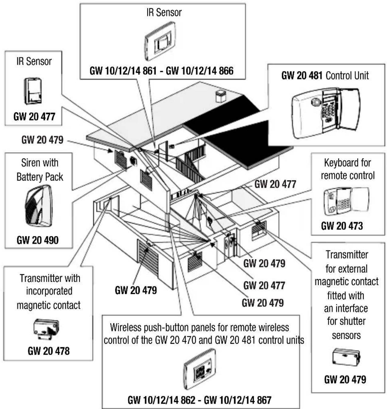
Operating layout of the wireless system managed by GW 20481 control units.
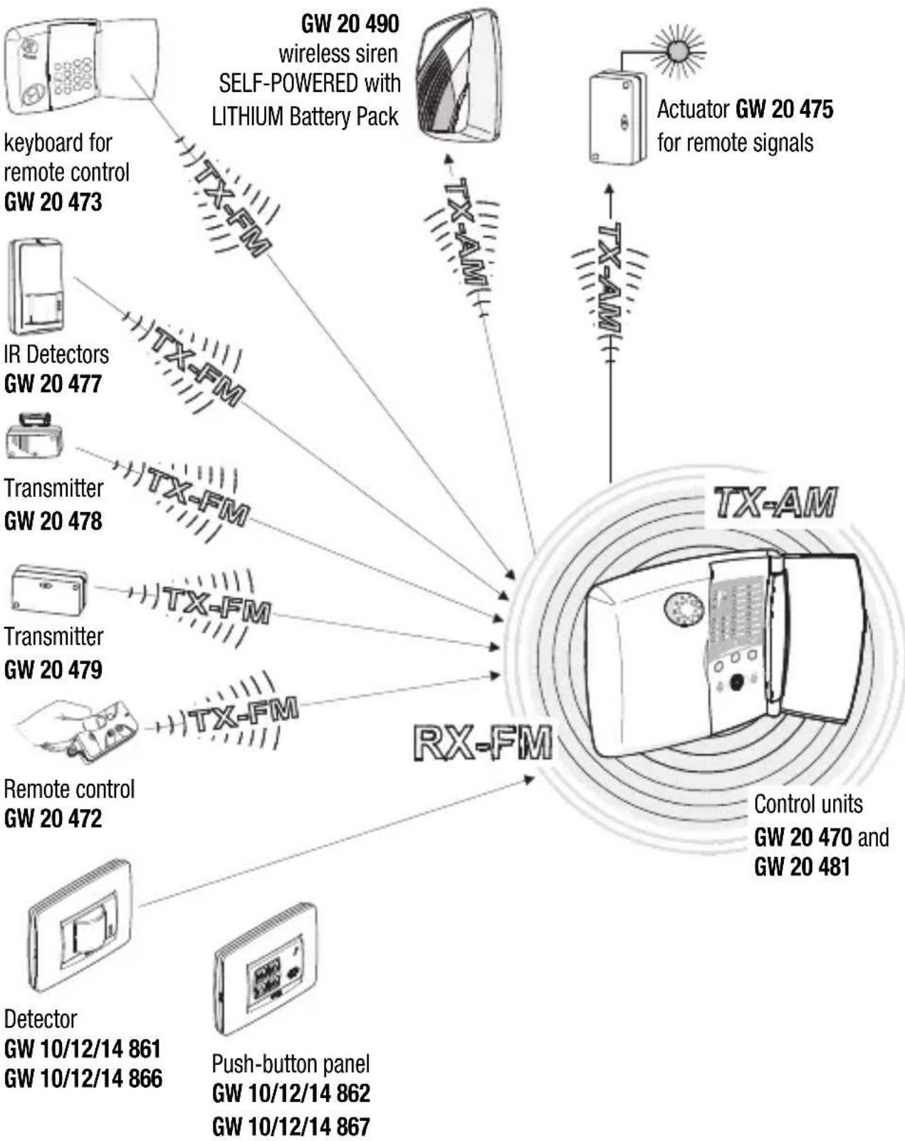
Control units
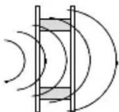
The installation of the sensor must comply with a number of rules to avoid a decrease in performance due to placement errors, in fact it is vital to accurately define the operative area of the receiver system within which the sensor is installed, the actual range of the sensors and the correct installation paying particular attention to the type of materials used to build the premises.
The drawings below show correct and incorrect installation positions, objects that can decrease RF signals and the obstruction caused by some building materials.
Installation
Critical low wireless signal situations:
| Devices that transmit or receive compatible digital codes towards and from GW 20 470 and GW 20481 control units | Cause of the disturbed signal | Quality of the transmitted and received signals |
| • GW 20 490 self-powered sirens • Actuator GW 20 475 for remote signals • GW 10/12/14 861 GW 10/12/14 866 IR detectors • GW 20 478 transmitter • GW 20 479 transmitter • GW 20 473 keyboard for remote control • Push-button panels: GW 10/12/14 862 GW 10/12/14 867 • GW 20 472 remote control | • Mirrors • Metal doors • Metal grids (such as for instance AIR VENTs and REINFORCED CONCRETE WALLS, FLOORS OR CEILINGS) | RX-FM GW 20 470 Control Unit green yellow red OK |
Attenuation of main building materials:
90% - 100%
of full capacity
walls in plywood or hollow panelling
65% - 95%
of full capacity

brick or perforated blocks
10% - 70%
of full capacity
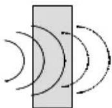
reinforced concrete or metal sheets and plastering
Plaque removal alarm magnet
To guarantee good system protection, the product generates a tamper-proof signal if the front plaque is removed.
The presence of the plate is checked by means of a tamper-proof magnet.
To make it function, you must assemble the magnet on the plaque using the kit supplied with the product. The kit contains:
-1 magnet;
- 1 double-sided adhesive to fix the magnet to the plaque;
-1 fixing template;
Steps
1.Fix the template to the back of the plaque, ensuring the insertion position is correct (for the LUX plaque, you must also check it is correctly orientated in relation to the GEWISS mark on the front frame);
2.Insert and fix the double-sided adhesive to the plaque, using the template cut-out as a reference;
3. Fix the magnet to the double-sided adhesive (be sure to centre it in relation to the arrows next to the cut-out)
4.Remove the fixing template;
5.Assemble the plaque on the product, respecting the correct position;
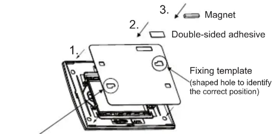
Second shaped hole, only on LUX plaques
If the magnet is not installed correctly, the sensor will send not only the presence signal but also the magnet open one, thereby generating an alarm in the control unit.
Electrical connections and selections
FRONT VIEW
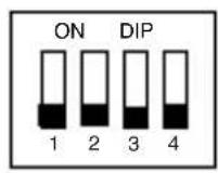
Operating options
DIP switch
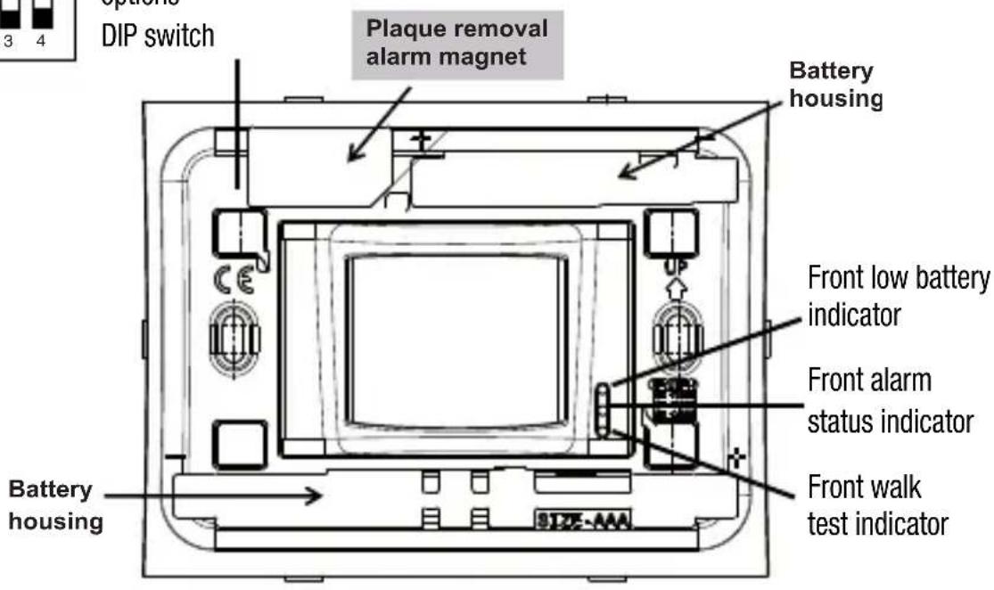
BACK VIEW
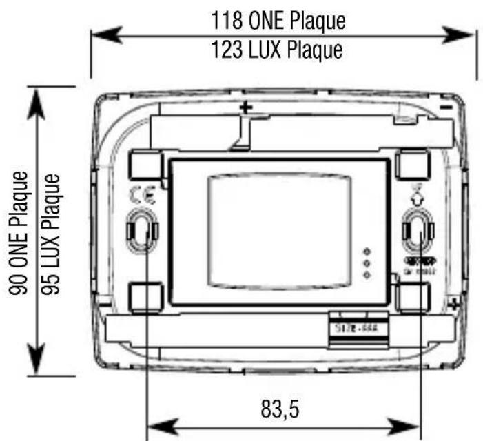
DIMENSIONS
Electrical connections and selections
OPERATING OPTIONS
The detector's operating options are set using the DIP switches:
DIP switch 1: WALK-TEST EXCLUSION
OFF: walk-test activated (default)
ON: walk-test excluded
DIP switch 2: LED EXCLUSION
OFF: LED switch-on activated (default)
ON: LED switch-on excluded
DIP switch 3: NUMBER OF ALARM IMPULSES SELECTION
OFF: 2 impulses in 8 seconds (default)
ON: 4 impulses in 8 seconds
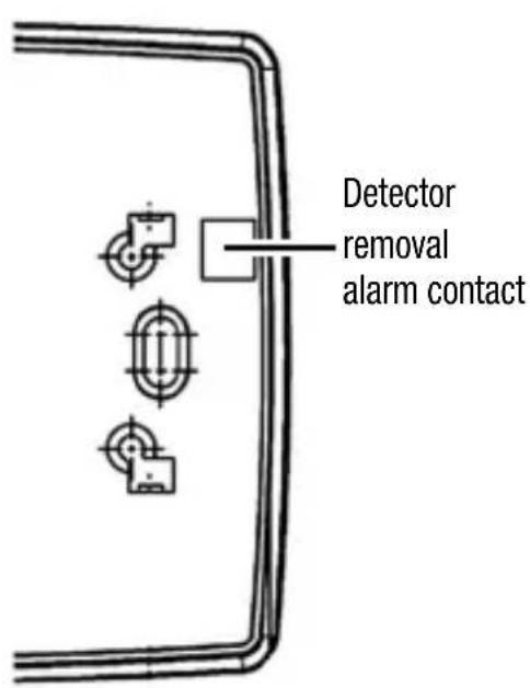
DIP switch 4: DETECTOR REMOVAL ALARM EXCLUSION
OFF: alarm removal activated (default)
ON: alarm removal excluded
WARNING: to increase the battery life it is recommended to disable the signal indicators: the autonomy is reduced by 10% with the walk-test indicator inserted.
Electrical connections and selections
WALK-TEST
The walk-test mode is used for testing the detector and checking the zone of coverage. If the walk-test function is activated (DIP switch 1 OFF), after the initialization delay (when the appliance is first switched on), the detector automatically enters walk-test mode and remains in it for 10 minutes, after which the sensor automatically passes into operating mode.
When a presence is detected, the sensor signals walk-test mode by making all three LEDs blink. In walk-test mode the transmission inhibition time is reduced to 30 seconds. The transmission is signalled by making all the LEDs blink 3 times.
The automatic exit from walk-test mode after 10 minutes allows the installation to be speeded up since it is not necessary to reopen the sensor to exclude this function.
In case of need it is always possible to end walk-test mode immediately by setting DIP switch 1 to ON.
The LEDs are not switched on in the case of a flat battery (with the exception of the red LED followed by the yellow LED during alarm transmissions).
LED EXCLUSION
Exclusion of the LEDs allows switch-on to be disabled so as to increase the autonomy of the sensor's batteries by up to 10% .
If DIP switch 2 is ON, the signal LEDs are switched off in operating mode.
If DIP switch 2 is OFF, switching on the LEDs is enabled, but the green LED for detecting presences limits itself to switching on every 5 seconds, even if several impulses are detected (counted for the alarm signal in any case).
In walk-test mode the LEDs are switched on independently of this selection; after 10 minutes the sensor enters operating mode and the LEDs are kept switched off.
NOTE: the green LED is only switched on during the sensor inhibition time (5 minutes after each transmission); when the inhibition time has elapsed, with the sensor operational, the green LED no longer signals the impulses detected until the next alarm transmission and consequent new inhibition.
This way of operating, while permitting the correct operation of the sensor to be checked visually, prevents possible intruders from obtaining information on the operating status of the sensor and the area of coverage before an alarm is signalled.
Operating Options
NUMBER OF ALARM IMPULSES SELECTION
The selection of DIP switch 3 allows the definition of the number of presence impulses (two or four) that must be detected by the sensor (in an interval of 8 seconds) before an alarm is signalled. The choice must be made depending on the level of sensitivity it is required to give the burglar alarm system; greater sensitivity is obtained with two impulses (DIP switch 3 OFF) but also greater consumption and a consequent reduction of the autonomy of the batteries.
DETECTOR REMOVAL ALARM EXCLUSION
Selecting DIP switch 4 allows the activation or exclusion of the alarm linked to the removal of the detector following the opening of the alarm contact located on the back of the appliance itself.
OPERATING WITH A FLAT BATTERY
The detector signals flat battery when the batteries have reached the end of their operational life. The flat battery condition is communicated to the control unit and displayed by making the detector's yellow LED blink after each transmission. In flat battery conditions the green LED is kept switched off independently of the LED switch-on selection.
INITIALIZATION PHASE
Following the first switch-on of the detector, the appliance requires approximately 1 minute to stabilize itself and enter the operational operating mode.
The initialization phase is signalled by the continuous switch-on of the red LED.
When operating in operational conditions the detector sends an alarm transmission when the set number of impulses (two or four) are detected within a time interval of 8 seconds. To save on battery consumption the detector inhibits itself automatically for 5 minutes after each alarm transmission, after which the sensor is operational again and ready to signal possible further alarms. An alarm transmission is represented by the red LED blinking; in the case of a flat battery during the transmission the yellow LED is switched on immediately after having made the transmission itself while the green walk-test LED is deactivated to preserve the life of the batteries as long as possible.
Configuration programming
A) Remove the detector front plaque and assemble the magnet as shown on the previous pages
B) Insert the batteries into the plastic housing, being careful to respect the polarities marked on the detector.
C) Activate detector code acquisition mode on the GW 20 470 / GW 20 481 burglar alarm control units.
D) Position the plate near the sensitive area of the magnet (the red LED blinks once to indicate transmission made) in order to store the detector code in the control unit.
E) Set the detector's parameters on the control unit (belonging to the day/night group, entry/exit route, supervision, etc.).
F) Deactivate acquisition mode on the GW 20 470 / GW 20 481 control units.
G) Install the detector in the permitted positions (to this end it is useful to refer to the previous drawings). Replace the plaque and check the operation of the device with test transmissions.
WARNING: failure to take care in reclosing the container with the consequent Tamper circuit fault (detector removal alarm contact and plaque removal alarm magnet) leads to the generation of a tamper alarm at each transmission.
The tamper code is also appended to all other transmissions of the sensor: it is therefore possible, for example, that the alarm trips during the day due not to the movement registered by the sensor, ignored with the control unit switched off, but due to the tamper signal appended to the intrusion transmission just made.
Range of coverage drawings
STANDARD LENS
Lens coverage drawing with white light protection.
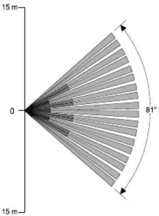
TOP VIEW
SIDE VIEW
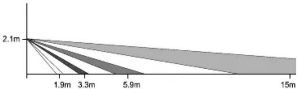
Range: 15 metres
Coverage: movement, 81^ open field
Band layout: 18 zones covering 4 floors
Operating examples
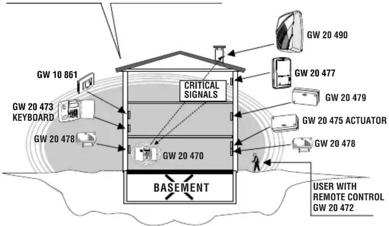
TX-RX RANGE OF THE GW 20 470 CONTROL UNIT
EXAMPLE 1:
Here the control unit is installed on the ground floor, in an off-centre positions, in a three floor building.
In this case the various architectonic infrastructures and the lack of "hostile" obstructions allow good transmission signals from most of the sensors and the keyboard towards the control unit, good transmission levels from the control unit towards the actuator but decrease both the self-powered siren command transmission signals and a reception signal from one of the GW 20 477 movement sensors.
Operating examples
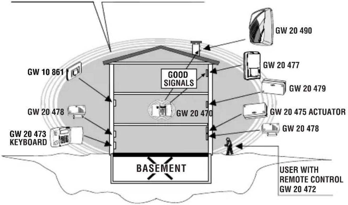
TX-RX RANGE OF THE GW 20 470 CONTROL UNIT
SOLUTION 1
One option is to move the control unit to a central position on the first floor.
This solution maintains the previous quality of the signals from the sensors and the actuator, and now permits good transmission levels from the control unit towards the self-powered siren and good reception from the GW 20 477 movement sensors, which were previously critical.
To make things easier for the user, the position of the keyboard on the ground floor is also moved without creating any signal problems.
Operating examples
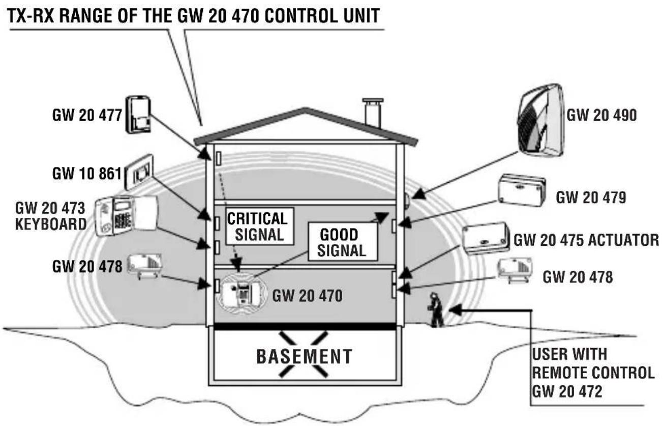
SOLUTION 2
It is not possible to move the control unit, but it is possible to change the positions of both the siren and the GW 20 477 sensor.
The solution retains the previous quality of the signals from the sensors and actuator and now permits good transmission from the control unit to the self-powered siren, but the critical signal in transmission of the GW 20 477 volumetric sensor remains.
Operating examples
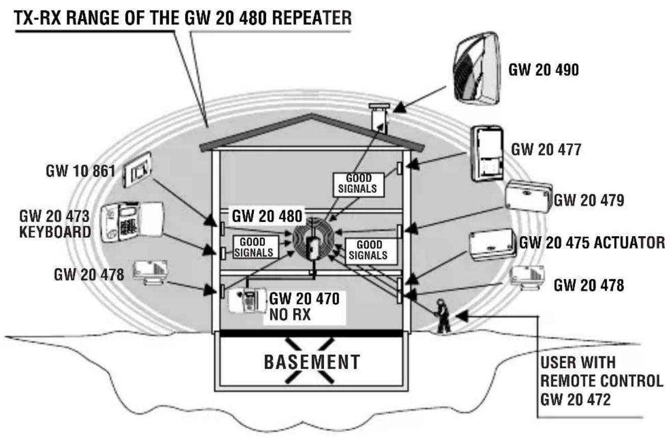
SOLUTION 3
This option uses a GW 20 480 type TX and RX repeater to be installed in the best possible position and connected by cable to the control unit.
In this case the GW 20480 repeater extends the control unit TX and RX signals, it automatically excludes the functions of the control unit RX circuit and becomes the convergence point for all the transmission and reception signals.
Adopting this solution it is possible to return to the original installation layout of the various devices as they all now transmit and receive good signals.
USER INSTRUCTIONS
Assembly operations
Opening and closing the case and inserting the batteries:
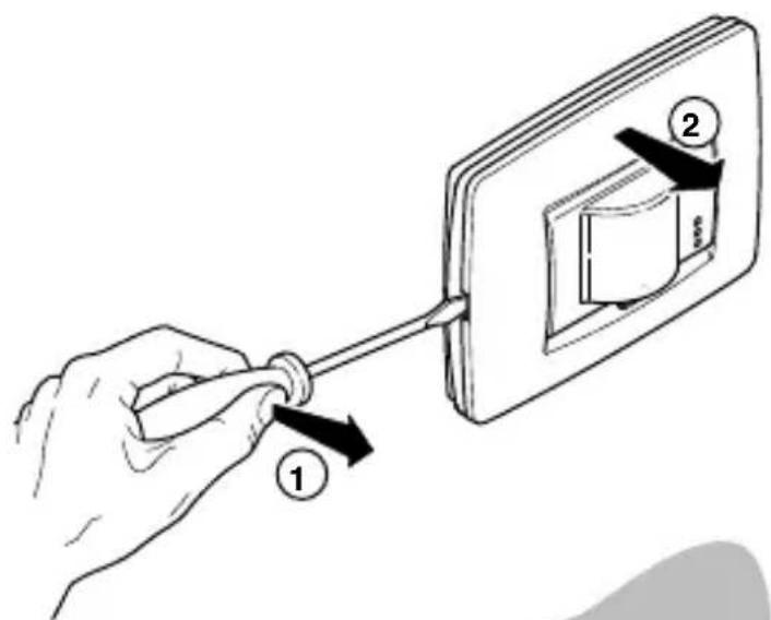
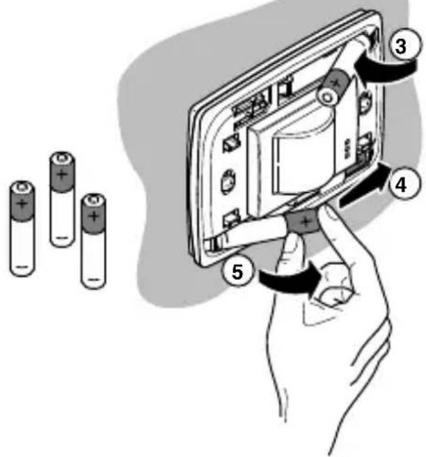
Insert 3 AAA alkaline batteries in the relative battery holder making sure the poles are in the right direction.
This appliance requires a battery to function properly. If the battery is replaced, make sure the old battery is disposed of according to the waste regulations foreseen by your local authorities.
FUNCTIONAL FEATURES / TECHNICAL DATA
Model: GW 10/12/14 861 - GW 10/12/14 866
Protection grade: IP3X
Power supply: n^ 3 AAA 1,5 V alkaline batteries.
Min/Max voltage 3V/4,5V
Low battery Voltage 3,7 V
Absorptions 9V: 16 A when idle, 20mA at TX peak.
Front LED indicators: Walk-test, alarm and low battery.
LEDs excluded: DIP switches for WALK-TEST, flat battery and alarm.
Alarm integration: Using the DIP switched selectable between
2 or 4 impulses in 8 seconds.
Capacity, coverage, sensitive areas: See the diagrams for the lens provided.
Timer: Constant movement inhibition, 5 minutes quiet after an alarm, with the WALK-TEST DIP switch activated, the transmission inhibition time is reduced to 30 seconds.
Sensor inhibition: About one minute delay when first switched on.
Tamper: Protection against removal of the detector from the wall
and removal of the plaque.
TX Frequency: Digital transmission on a LPD frequency.
Range: 50 metres in free-field conditions.
Autonomy: 2,5 years
NOTE: With indicators enabled the autonomy is reduced by at
least 10% , the flat battery signal is generated at 2/3
of the sensor's autonomy.
Working temperature: from -10^ to +45^ - 93% Ru.
ONE Plaque dimensions: L118 x H90 x P40 mm
LUX Plaque dimensions: L123 x H90 x P40 mm
Equipment: screws, expansion bolts, two-component adhesive for
fixing and kit tamper-proof magnet.
The GW 10/12/14 861 - GW 10/12/14 866 sensor is an accessory for compatible devices with EC markings; it complies to ETSI-300 220 Directive, to 89/336/CEE Standards relative to electromagnetic compatibility and to the 93/68/CEE Standard regarding low voltage safety.
FRANÇAIS
El dispositivo es compatible también con lareshareshareshareshareshareshareshareshareshareshareshareshareshareshareshareshareshareshareshareshareshareshareshareshareshareshareshareshareshareshareshareshareshareshareshareshareshareshareshareshareshareshareshareshareshareshareshareshareshareshareshahashashashashashashashashashashashashashashashashashashashashashashashashashashashashashashashashashashashashashashashashashashashashashashashashashashashashashashashashashashashashashashashashashashashashashashashashashashashashashashashashashashashashashashashasheshaheshaheshaheshaheshaheshaheshaheshaheshaheshaheshaheshaheshaheshaheshaheshaheshaheshaheshaheshaheshaheshaheshaheshaheshaheshaheshaheshaheshaheshaheshaheshaheshaheshaheshaheshaheshaheshaheshaheshaheshaheshaheshaheshaheshaheshaheshaheshaheshahshaheshaheshaheshahshaheshahshaheshahshahshahshahshahshahshahshahshahshahshahshahshahshahshahshahshahshahshahshahshahshahshahshahshahshahshahshahshahshahshahshahshahshahshahshahshahshahshahshahshahshahshahshahshahshahshahshahshahshahshah
ON: walk test excluding
DIP switch 2: EXCLUSION LED
OFF: encendido LED activado (default)
ON: encendido LED除外
DIP switch 3: SELECTION NUMERO IMPULSOS ALARMA
OFF: 2 impulsos en 8 segundos (default)
| Geräte, dieCompatible Digitalcodes an die Zentralen senden oder von diesen empfängen GW 20 470 und GW 20 481 | Ursachen der Signalstörung | Qualität der gesendeten und empfangenen Signale |
| · Eigenversorgte Sirene GW 20 490 · GW 20 475 Antrieb für Fernsignalisierungen · IR-Melder GW 10/12/14 861 GW 10/12/14 866 · Sender GW 20 478 · Sender GW 20 479 · Tastatur GW 20 473 für Fernsteuerung · Tastaturen: GW 10/12/14 862 GW 10/12/14 867 · Fernbedienung GW 20 472 | · Spiegel · Metalltore · Metallgitter (z.B. LUFTSCHÄCH-TE und MAUERN, FUSSBÖDEN, DECKEN aus STAHLBETON) | RX-FM Zentrale GW 20 470 grün grün gelb rot OK OK OK OK OK OK OK OK OK OK OK OK OK OK OK OK OK OK OK OK OK OK OK OK OK OK OK OK OK OK OK OK OK OK OK OK OK OK OK OK OK OK OK OK OK OK OK OK OK OK OK ok ok ok ok ok ok ok ok ok ok ok ok ok ok ok ok ok ok ok ok ok ok ok ok ok ok ok ok ok ok ok ok ok ok ok ok ok ok ok ok ok ok ok ok ok ok ok ok ok ok OK OK OK OK OK OK OK OK OK OK OK OK OK OK OK OK OK OK OK OK OK OK OK OK OK OK OK OK OK OK OK OK OK OK OK OK OK OK OK OK OK OK OK OK OK OK OK OK OK UK UK UK UK UK UK UK UK UK UK UK UK UK UK UK UK UK UK UK UK UK UK UK UK UK UK UK UK UK UK UK UK UK UK UK UK UK UK UK UK UK UK UK UK UK UK UK UK UK UK OK OK OK OK OK OK OK OK OK OK OK OK OK OK OK OK OK OK OK OK OK OK OK OK OK OK OK OK OK OK OK OK OK OK OK OK OK OK OK OK OK OK OK OK OK OK OK OK OK Ok OK OK OK OK OK OK OK OK OK OK OK OK OK OK OK OK OK OK OK OK OK OK OK OK OK OK OK OK OK OK OK OK OK OK OK OK OK OK OK OK OK OK OK OK OK OK OK OK OK K OK OK OK OK OK OK OK OK OK OK OK OK OK OK OK OK OK OK OK OK OK OK OK OK OK OK OK OK OK OK OK OK OK OK OK OK OK OK OK OK OK OK OK OK OK OK OK OK OK DK DK DK DK DK DK DK DK DK DK DK DK DK DK DK DK DK DK DK DK DK DK DK DK DK DK DK DK DK DK DK DK DK DK DK DK DK DK DK DK DK DK DK DK DK DK DK DK DK DK OK OK OK OK OK OK OK OK OK OK OK OK OK OK OK OK OK OK OK OK OK OK OK OK OK OK OK OK OK OK OK OK OK OK OK OK OK OK OK OK OK OK OK OK OK OK OK OK OK AK AK AK AK AK AK AK AK AK AK AK AK AK AK AK AK AK AK AK AK AK AK AK AK AK AK AK AK AK AK AK AK AK AK AK AK AK AK AK AK AK AK AK AK AK AK AK AK AK AK OK OK OK OK OK OK OK OK OK OK OK OK OK OK OK OK OK OK OK OK OK OK OK OK OK OK OK OK OK OK OK OK OK OK OK OK OK OK OK OK OK OK OK OK OK OK OK OK OK IK IK IK IK IK IK IK IK IK IK IK IK IK IK IK IK IK IK IK IK IK IK IK IK IK IK IK IK IK IK IK IK IK IK IK IK IK IK IK IK IK IK IK IK IK IK IK IK IK IK OK OK OK OK OK OK OK OK OK OK OK OK OK OK OK OK OK OK OK OK OK OK OK OK OK OK OK OK OK OK OK OK OK OK OK OK OK OK OK OK OK OK OK OK OK OK OK OK OK EK EK EK EK EK EK EK EK EK EK EK EK EK EK EK EK EK EK EK EK EK EK EK EK EK EK EK EK EK EK EK EK EK EK EK EK EK EK EK EK EK EK EK EK EK EK EK EK EK EK OK OK OK OK OK OK OK OK OK OK OK OK OK OK OK OK OK OK OK OK OK OK OK OK OK OK OK OK OK OK OK OK OK OK OK OK OK OK OK OK OK OK OK OK OK OK OK OK OK 20000000000000000000000000000000000000000000000000000000000000000000000000000000000000000000000000000 OK OK OK OK OK OK OK OK OK OK OK OK OK OK OK OK OK OK OK OK OK OK OK OK OK OK OK OK OK OK OK OK OK OK OK OK OK OK OK OK OK OK OK OK OK OK OK OK OK JISCAI JISCAI JISCAI JISCAI JISCAI JISCAI JISCAI JISCAI JISCAI JISCAI JISCAI JISCAI JISCAI JISCAI JISCAI JISCAI JISCAI JISCAI JISCAI JISCAI JISCAIA JISCAIA JISCAIA JISCAIA JISCAIA JISCAIA JISCAIA JISCAIA JISCAIA JISCAIA JISCAIA JISCAIA JISCAIA JISCAIA JISCAIA JISCAIA JISCAIA JISCAIA JISCAIA JISCAIA JISCAII JISCAII JISCAII JISCAII JISCAII JISCAII JISCAII JISCAII JISCAII JISCAII JISCAII JISCAII JISCAII JISCAII JISCAII JISCAII JISCAII JISCAII JISCAII JISCAII JISCAIA JISCAIA JISCAIA JISCAIA JISCAIA JISCAIA JISCAIA JISCAIA JISCAIA JISCAIA JISCAIA JISCAIA JISCAIA JISCAIA JISCAIA JISCAIA JISCAIA JISCAIA JISCAIA JISCAIAN JISCAIAN JISCAIAN JISCAIAN JISCAIAN JISCAIAN JISCAIAN JISCAIAN JISCAIAN JISCAIAN JISCAIAN JISCAIAN JISCAIAN JISCAIAN JISCAIAN JISCAIAN JISCAIAN JISCAIAN JISCAIAN JISCAIAN JISCAIA JISCAIA JISCAIA JISCAIA JISCAIA JISCAIA JISCAIA JISCAIA JISCAIA JISCAIA JISCAIA JISCAIA JISCAIA JISCAIA JISCAIA JISCAIA JISCAIA JISCAIA JISCAIA JISCAI JISCAIA JISCAIA JISCAIA JISCAIA JISCAIA JISCAIA JISCAIA JISCAIA JISCAIA JISCAIA JISCAIA JISCAIA JISCAIA JISCAIA JISCAIA JISCAIA JISCAIA JISCAIA JISCAIAN JISCAIA JISCAIA JISCAIA JISCAIA JISCAIA JISCAIA JISCAIA JISCAIA JISCAIA JISCAIA JISCAIA JISCAIA JISCAIA JISCAIA JISCAIA JISCAIA JISCAIA JISCAIA JISCAIAN JISCAII JISCAII JISCAII JISCAII JISCAII JISCAII JISCAII JISCAII JISCAII JISCAII JISCAII JISCAII JISCAII JISCAII JISCAII JISCAII JISCAII JISCAII JISCAII JISCAI JISCAII JISCAII JISCAII JISCAII JISCAII JISCAII JISCAII JISCAII JISCAII JISCAII JISCAII JISCAII JISCAII JISCAII JISCAII JISCAII JISCAII JISCAII JISCAII JISCAIAN JISCAII JISCAII JISCAII JISCAII JISCAII JISCAII JISCAII JISCAII JISCAII JISCAII JISCAII JISCAII JISCAII JISCAII JISCAII JISCAII JISCAII JISCAII JISCAIAN JISCAI JISCAII JISCAII JISCAII JISCAII JISCAII JISCAII JISCAII JISCAII JISCAII JISCAII JISCAII JISCAII JISCAII JISCAII JISCAII JISCAII JISCAII JISCAII JISCAI JISCAI JISCAII JISCAII JISCAII JISCAII JISCAII JISCAII JISCAII JISCAII JISCAII JISCAII JISCAII JISCAII JISCAII JISCAII JISCAII JISCAII JISCAII JISCAII JISCAIAN JISCAIAN JISCAIAN JISCAIAN JISCAIAN JISCAIAN JISCAIAN JISCAIAN JISCAIAN JISCAIAN JISCAIAN JISCAIAN JISCAIAN JISCAIAN JISCAIAN JISCAIAN JISCAIAN JISCAIAN JISCAIAN JISCAII JISCAII JISCAII JISCAIAN JISCAIAN JISCAIAN JISCAIAN JISCAIAN JISCAIAN JISCAIAN JISCAIAN JISCAIAN JISCAIAN JISCAIAN JISCAIAN JISCAIAN JISCAIAN JISCAIAN JISCAIAN JISCAII JISCAII JISCAIAN JISCAIAN JISCAIAN JISCAIAN JISCAIAN JISCAIAN JISCAIAN JISCAIAN JISCAIAN JISCAIAN JISCAIAN JISCAIAN JISCAIAN JISCAIAN JISCAIAN JISCAIAN JISCAIAN JISCAII JISCAII JISCAIAN JISCAII JISCAIAN JISCAIAN JISCAIAN JISCAIAN JISCAIAN JISCAIAN JISCAIAN JISCAIAN JISCAIAN JISCAIAN JISCAIAN JISCAIAN JISCAIAN JISCAIAN JISCAIAN JISCAIAN JISCAIAN JISCAIAN JISCAII JISCAIAN JISCAIAN JISCAIAN JISCAIAN JISCAIAN JISCAIAN JISCAIAN JISCAIAN JISCAIAN JISCAIAN JISCAIAN JISCAIAN JISCAIAN JISCAIAN JISCAIAN JISCAIAN JISCAIAN JISCAII JISCAIAN JISCAII JISCAIAN JISCAIAN JISCAIAN JISCAIAN JISCAIAN JISCAIAN JISCAIAN JISCAIAN JISCAIAN JISCAIAN JISCAIAN JISCAIAN JISCAIAN JISCAIAN JISCAIAN JISCAIAN JISCAII JISCAIAN JISCAIAN JISCAII JISCAIAN JISCAIAN JISCAIAN JISCAIAN JISCAIAN JISCAIAN JISCAIAN JISCAIAN JISCAIAN JISCAIAN JISCAIAN JISCAIAN JISCAIAN JISCAIAN JISCAIAN JISCAIAN JISCAII JISCAII JISCAII JISCAII JISCAIAN JISCAIAN JISCAIAN JISCAIAN JISCAIAN JISCAIAN JISCAIAN JISCAIAN JISCAIAN JISCAIAN JISCAIAN JISCAIAN JISCAIAN JISCAIAN JISCAIAN JISCAII JISCAIAN JISCAIAN JISCAIAN JISCAII JISCAIAN JISCAIAN JISCAIAN JISCAIAN JISCAIAN JISCAIAN JISCAIAN JISCAIAN JISCAIAN JISCAIAN JISCAIAN JISCAIAN JISCAIAN JISCAIAN JISCAIAN JISCAII JISCAIAN JISCAIAN JISCAII JISCAII JISCAIAN JISCAIAN JISCAIAN JISCAIAN JISCAIAN JISCAIAN JISCAIAN JISCAIAN JISCAIAN JISCAIAN JISCAIAN JISCAIAN JISCAIAN JISCAIAN JISCAIAN JISCAII JISCAIAN JISCAII JISCAIAN JISCAII JISCAIAN JISCAIAN JISCAIAN JISCAIAN JISCAIAN JISCAIAN JISCAIAN JISCAIAN JISCAIAN JISCAIAN JISCAIAN JISCAIAN JISCAIAN JISCAIAN JISCAIAN JISCAII JISCAIAN JISCAII JISCAII JISCAIAN JISCAIAN JISCAIAN JISCAIAN JISCAIAN JISCAIAN JISCAIAN JISCAIAN JISCAIAN JISCAIAN JISCAIAN JISCAIAN JISCAIAN JISCAIAN JISCAIAN JISCAIAN JISCAII JISCAIAN JISCAII JISCAII JISCAII JISCAIAN JISCAIAN JISCAIAN JISCAIAN JISCAIAN JISCAIAN JISCAIAN JISCAIAN JISCAIAN JISCAIAN JISCAIAN JISCAIAN JISCAIAN JISCAIAN JISCAIAN JISCAII JISCAII JISCAIAN JISCAIAN JISCAII JISCAIAN JISCAIAN JISCAIAN JISCAIAN JISCAIAN JISCAIAN JISCAIAN JISCAIAN JISCAIAN JISCAIAN JISCAIAN JISCAIAN JISCAIAN JISCAIAN JISCAIAN JISCAII JISCAII JISCAIAN JISCAII JISCAII JISCAIAN JISCAIAN JISCAIAN JISCAIAN JISCAIAN JISCAIAN JISCAIAN JISCAIAN JISCAIAN JISCAIAN JISCAIAN JISCAIAN JISCAIAN JISCAIAN JISCAIAN JISCAII JISCAII JISCAII JISCAIAN JISCAII JISCAIAN JISCAIAN JISCAIAN JISCAIAN JISCAIAN JISCAIAN JISCAIAN JISCAIAN JISCAIAN JISCAIAN JISCAIAN JISCAIAN JISCAIAN JISCAIAN JISCAIAN JISCAII JISCAII JISCAII JISCAII JISCAII JISCAIAN JISCAIAN JISCAIAN JISCAIAN JISCAIAN JISCAIAN JISCAIAN JISCAIAN JISCAIAN JISCAIAN JISCAIAN JISCAIAN JISCAIAN JISCAIAN JISCAII JISCAII JISCAIAN JISCAIAN JISCAIAN JISCAII JISCAIAN JISCAIAN JISCAIAN JISCAIAN JISCAIAN JISCAIAN JISCAIAN JISCAIAN JISCAIAN JISCAIAN JISCAIAN JISCAIAN JISCAIAN JISCAIAN JISCAII JISCAII JISCAIAN JISCAIAN JISCAII JISCAII JISCAIAN JISCAIAN JISCAIAN JISCAIAN JISCAIAN JISCAIAN JISCAIAN JISCAIAN JISCAIAN JISCAIAN JISCAIAN JISCAIAN JISCAIAN JISCAIAN JISCAII JISCAII JISCAIAN JISCAII JISCAIAN JISCAII JISCAIAN JISCAIAN JISCAIAN JISCAIAN JISCAIAN JISCAIAN |
Hereby, GEWISS declares that this device is in compliance with the essential requirements and other relevant provisions of Directive 1999/5/EC.
The declaration of conformity may be requested at the following address:
GEWISS S.p.A Via A. Volta 1, 24069 Cenate Sotto (BG) Italia Tel: +39 035 946 111 Fax: +39 035 945 270 E-mail: qualitymarks@gewiss.com
According to article 9 paragraph 2 of the European Directive 2004/108/EC, GEWISS S.p.A is also responsible for placing the apparatus on the Community market.


+39 035 946 111
8.30-12.30/14.00-18.00
lunedi ÷ venerdi - monday ÷ friday

+39 035 946 260

sat@gewiss.com
www.gewiss.com


- MANUALE D'USO ANTINTRUSIONE
- NOTICE D'UTILISATION ANTI-INTRUSION
- Wall-mounted infrared ray volumetric presence detector
- WARNING
- FOR THE INSTALLER:
- FOR THE OPERATOR
- Movement detector for wireless burglar alarm systems using GW 20 470 and GW 20 481 control units.
- CONTENTS
- USER INSTRUCTIONS page
- General information
- Operating layout of the wireless system managed by GW 20481 control units.
- Control units
- Installation
- Plaque removal alarm magnet
- Steps
- Electrical connections and selections
- OPERATING OPTIONS
- WALK-TEST
- LED EXCLUSION
- NUMBER OF ALARM IMPULSES SELECTION
- DETECTOR REMOVAL ALARM EXCLUSION
- OPERATING WITH A FLAT BATTERY
- INITIALIZATION PHASE
- Configuration programming
- Range of coverage drawings
- STANDARD LENS
- Operating examples
- EXAMPLE 1:
- SOLUTION 1
- SOLUTION 2
- SOLUTION 3
- USER INSTRUCTIONS
- Assembly operations
- FUNCTIONAL FEATURES / TECHNICAL DATA
- FRANÇAIS
Brand : Gewiss
Model : GW10861
Category : Motion detector