
GW20477 - Motion detector Gewiss - Free user manual and instructions
Find the device manual for free GW20477 Gewiss in PDF.


| Brand | Gewiss |
| Model | GW20477 |
| Product type | Motion detector |
| Power supply | 230 V AC, 50 Hz |
| Detection angle | 180° |
| Maximum range | 12 m |
| Sensitivity adjustment | Yes |
| Time delay adjustment | Yes (5 seconds to 30 minutes) |
| Operating temperature | -10 °C to +40 °C |
| Protection rating | IP44 |
| Dimensions (W x H x D) | 70 x 70 x 40 mm |
| Weight | 100 g |
| Material | ABS plastic |
| Color | White |
| Installation | Wall-mounted, indoor or outdoor |
| Maintenance | Clean with a soft, dry cloth |
| Safety | Disconnect power before any intervention |
| Warranty | 2 years |
Frequently Asked Questions - GW20477 Gewiss
User questions about GW20477 Gewiss
0 question about this device. Answer the ones you know or ask your own.
Ask a new question about this device
Download the instructions for your Motion detector in PDF format for free! Find your manual GW20477 - Gewiss and take your electronic device back in hand. On this page are published all the documents necessary for the use of your device. GW20477 by Gewiss.
USER MANUAL GW20477 Gewiss
natural_image
Line drawing of a rectangular electronic device with a lid and front panel (no text or symbols)GW 20 477
AVVERTENZE
PER L'INSTALLATORE:
line
| Distance | Value | | -------- | ----- | | 1.9m | 2.1m | | 3.3m | | | 5.9m | | | 15m | |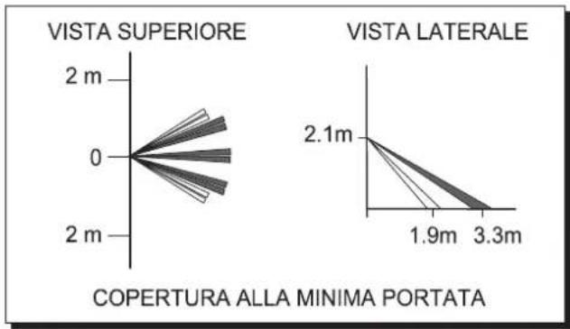
line
| View | Distance (m) | | ---------------- | ------------ | | VISTA SUPERIORE | 0 | | VISTA LATERALE | 2.1 | | COPERTURA ALLA MINIMA PORTATA | 1.9 | | COPERTURA ALLA MINIMA PORTATA | 3.3 |8. OPERATIVITA'
flowchart
graph TD
    A["TAX-AM"] --> B["Non Collegato"]
    B --> C["TAX-FM"]
    C --> D["TAX-FM"]
    D --> E["TAX-FM"]
    E --> F["TAX-FM"]
    F --> G["TAX-FM"]
    G --> H["TAX-FM"]
    H --> I["TAX-FM"]
    I --> J["TAX-FM"]
    J --> K["TAX-FM"]
    K --> L["TAX-FM"]
    L --> M["TAX-FM"]
    M --> N["TAX-FM"]
    N --> O["TAX-FM"]
    O --> P["TAX-FM"]
    P --> Q["TAX-FM"]
    Q --> R["TAX-FM"]
    R --> S["TAX-FM"]
    S --> T["TAX-FM"]
    T --> U["TAX-FM"]
    U --> V["TAX-FM"]
    V --> W["TAX-FM"]
    W --> X["TAX-FM"]
    X --> Y["TAX-FM"]
    Y --> Z["TAX-FM"]
    Z --> AA["TAX-FM"]
    AA --> AB["TAX-FM"]
    AB --> AC["TAX-FM"]
    AC --> AD["TAX-FM"]
    AD --> AE["TAX-FM"]
    AE --> AF["TAX-FM"]
    AF --> AG["TAX-FM"]
    AG --> AH["TAX-FM"]
    AH --> AI["TAX-FM"]
    AI --> AJ["TAX-FM"]
    AJ --> AK["TAX-FM"]
    AK --> AL["TAX-FM"]
    AL --> AM["TAX-FM"]
    AM --> AN["TAX-FM"]
    AN --> AO["TAX-FM"]
    AO --> AP["TAX-FM"]
    AP --> AQ["TAX-FM"]
    AQ --> AR["TAX-FM"]
    AR --> AS["TAX-FM"]
    AS --> AT["TAX-FM"]
    AT --> AU["TAX-FM"]
    AU --> AV["TAX-FM"]
    AV --> AW["TAX-FM"]
    AW --> AX["TAX-FM"]
    AX --> AY["TAX-FM"]
    AY --> AZ["TAX-FM"]
    AZ --> BA["TAX-FM"]
    BA --> BB["TAX-FM"]
    BB --> BC["TAX-FM"]
    BC --> BD["TAX-FM"]
    BD --> BE["TAX-FM"]
    BE --> BF["TAX-FM"]
    BF --> BG["TAX-FM"]
    BG --> BH["TAX-FM"]
    BH --> BI["TAX-FM"]
    BI --> BJ["TAX-FM"]
    BJ --> BK["TAX-FM"]
    BK --> BL["TAX-FM"]
    BL --> BM["TAX-FM"]
    BM --> BN["TAX-FM"]
    BN --> BO["TAX-FM"]
    BO --> BP["TAX-FM"]
    BP --> BQ["TAX-FM"]
    BQ --> BR["TAX-FM"]
    BR --> BS["TAX-FM"]
    BS --> BT["TAX-FM"]
    BT --> BU["TAX-FM"]
    BU --> BV["TAX-FM"]
    BV --> BW["TAX-FM"]
    BW --> BX["TAX-FM"]
    BX --> BY["TAX-FM"]
    BY --> BZ["TAX-FM"]
Carefully follow all operating regulations applicable to the installing of electrical and security system, further to the specifications supplied by the manufacturer in the instruction manual which comes with the products.
Provide the operators with all the instructions for use and the limits of the installed system, specifying that there are specific standards and different levels of safety performance that must be adjusted to the relative user requirements.
Make sure the operator acknowledges the warnings provided in this document.
FOR THE OPERATOR:
Periodically and carefully check that the system is functional and the enabling and disenabling procedures are performed correctly.
Perform period maintenance on the system using specialised personnel who have the qualifications foreseen by the laws in force. Ask the installer to check the adequacy of the system if any operating conditions change (e.g. variations in the extension of the areas to be protected, change in the access procedures etc...)
[EMPTY]
This device has been designed, built and tested with maximum care, adopting control procedures which all conform to the regulations in force. Full compliance of the functional characteristics is exclusively achieved in the case where its use is limited to the functions it was designed for, and that is:
Passive infrared detector for wireless burglar alarm systems using GW 20 470 and GW 20 481 control units
No other use or implementation is contemplated and it is therefore impossible to guarantee it will function correctly.
The production processes are carefully supervised to prevent defects and malfunctions; nevertheless the components used are subject to extremely low percentages of faults, as in the case of all electronic or mechanical part. Due to the destination of use of this device (protection of persons and things) we invite the user to adjust the levels of protection provided by the system to the actual risk levels in loco (assessing the possibility that this system can operate in a degraded manner due to malfunctions or faults etc) bearing in mind that there are precise regulations foreseen for the planning and installation of systems destined to this type of application.
The attention of the operator (system user) is recalled to the need to perform regular periodic maintenance on the system, and at least comply with what foreseen by the regulations in force, and also check, at intervals which are appropriate to the risk levels, that the system functions correctly, testing the signals on the control unit, the sensors, acoustic alarms, telephone combiners and all other connected devices. On completing the periodic controls, the operator must promptly notify the installer of the results.
The planning, installation and maintenance of the systems incorporated in this product are reserved to personnel who are duly trained and qualified to operate in a secure manner in compliance with accident prevention regulations. It is essential that they are installed in compliance with the regulations in force. The internal parts of some devices are connected to the mains and therefore there is a risk of electrocution in the case where maintenance operations are performed without disconnecting both the primary and emergency power supplies. Some products use rechargeable or normal batteries for emergency power supplies. If they are connected incorrectly it could damage the product, damage things and endanger the situation of the operator (explosions and fires).
Stamp of the installer company:
1. GENERAL INFORMATION
The passive infrared sensor GW 20 477 is an independent device which is capable of detecting the presence of infrared energy generated by the movement of a person within the area controlled by the sensor. The alarm, tamper and surveillance alarms statuses enable the transmission, the low battery status is automatically queued to the first useful transmission.
The radio signal is coded and only compatible with the GW 20 470 and GW 20 481 control units; it is powered by a standard supplied 3.6V 1.2Ah lithium battery (Lithium – Thionyl Chloride), that guarantees an autonomy of years of activity, see the specification table, the operative range is 100 metres in open field.
To identify the remote device, a digital code is transmitted using the frequency foreseen for low power devices (LPD). The code is generated when the device is installed, a valid random code using a 34 billion combination system is transmitted; a reception collision-proof procedure is activated to increase the level of security on the system.
The sensor incorporates the following functions: A sophisticated alarm generation circuit with coded radio transmission, LED display, an integration system (with option of two or four impulses in 5 seconds) to eliminate any alarms caused by puntiform and sudden overheating. GW 20 477 is fitted with a 5 minute inhibition timer, between one alarm and another, to protect the battery charge used in the case of continuous movement in the protected area. The internal battery is constantly monitored to detect its charge status and any malfunction signal will be queued and transmitted with the next useful transmission.
A time which can be programmed and excluded is activated to transmit surveillance to the reception device, and the incorporated indicator LEDs (which can be excluded) signal the operating status of the sensor.
It is recommended to follow the basic installation instructions for infrared detectors provided in this manual.
- CHARACTERISTICS
| Model: GW 20477 | Coding: | Factory set transmission code Valid code with 2 billion combinations. | |
| Protection rating: IP3X | TX for surveillance: | 30 minute interval between two surveillance transmissions which can not be modified. | |
| Level of Performance: CEI 79-2 Level I, CEI 79-16 Level B | |||
| Power supply: 3.6V 1.2Ah lithium battery (Lithium – Thionyl Chloride) | TX Frequency: | Digital transmission on a LPD frequency. | |
| Range: | 100 metres in free-field conditions. | ||
| Min. voltage: 2,6V | Autonomy: | 3 years with a ER14250 battery. | |
| Low battery voltage: 3V (reinstatement 3.1V) | NOTA: | With indicators enabled the autonomy is reduced by at least 15%, the flat battery signal is generated at 2/3 of the sensor's autonomy. | |
| Absorptions @ 3,6V: 16 μA when idle, 11 mA at TX peak. | |||
| Front LED indicators: Walk-test, alarm and low battery. | Running temperature: from -10°C to +45°C - 93% Ru. | ||
| Dip switch for: | Tamper enabling/exclusion, WALK-TEST, indicator pilot lights, alarm impulse integration. | Size, weight: L 64 x H 110 x P 48 mm,P 95 if installed with joint. | |
| Alarm integration: | Select 2 or 4 impulses in an 8 second time window. | 100 grams without battery. | |
| Capacity, coverage, sensitive areas: | See the diagrams for the lens provided. | Equipment: | Screws and dowels, battery,instruction manual.Standard supplied jointed bracket. |
| Timer: | 5 minute pause after an alarm, in WALK-TEST 30s pause between two successive alarms during function tests.Max WALK-TEST time 10 minutes. | ||
| Sensor inhibition: | 1 minute delay when first switched on. | The GW 20477 sensor is an accessory for compatible devices with EC markings; it complies to ETSI-300 220 Directive, to 89/336/CEE Standards relative to electromagnetic compatibility and to the 93/68/CEE Standard regarding low voltage safety. | |
| Tamper: | Protection against opening and removal of the case. | ||
3. INSTALLATION
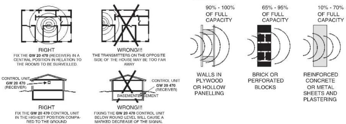
The installation of the sensor must comply with a number of rules to avoid a decrease in performance due to placement errors, in fact it is vital to accurately define the operative area of the receiver system within which the sensor is installed, the actual range of the sensors and the correct installation paying particular attention to the type of materials used to build the premises. The drawings below show correct and incorrect installation positions, objects that can decrease RF signals and the obstruction caused by some building materials.
Installation situations. Decrease of the radio signal caused by certain types of building materials.
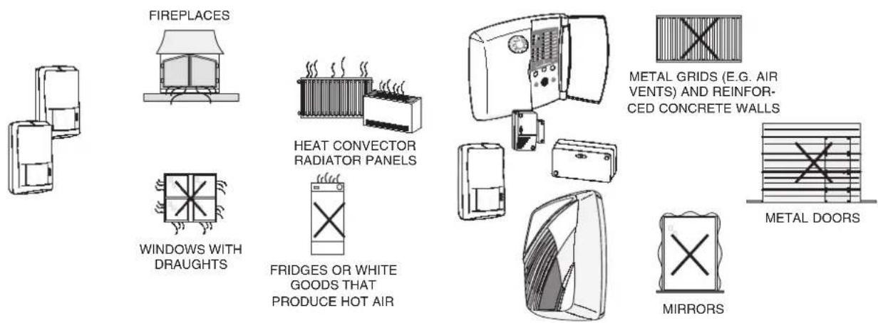
Disturbed operating situations for the sensor. Objects that can modify/decrease the range capacity.
WARNING: If the casing is not closed properly, there will be a malfunction in the Tamper circuit which will activate a tamper alarm during each surveillance transmission.
The tamper code is queued to each sensor transmission, it is therefore possible, for instance, that the alarm will be activated during the day, not due to a movement recorded by the sensor, ignored when the control unit is disarmed, but due to the tamper signal queued to the burglar alarm transmission made.
View of the sensor electronic card.

WARNING: to increase the battery life it is recommended to disable the signal indicators: the autonomy is reduced by 15% with the walk-test indicator inserted.
5. FIRST POWER-UP PROCEDURE
Great care must be taken when powering up the GW 20 477 transmitter for the first time, please follow the procedure below step by step:
1) Remove the insulating protection tab from the battery, as seen in the Fig. above.
2) Press and release the TAMPER button 3-4 times.
3) Reset any low battery signals in the control unit or the compatible reception device.
WARNING: when new batteries are used, or batteries that have not been used for a long time, they may generate a low battery error message during power-up. This is caused by the chemical composition of the Lithium Thionyl Chloride batteries and can be resolved by following the instructions above.
If the battery is to be exposed to low temperatures, it is recommended to store the battery at room temperature before loading it.
6. TAMPER PROTECTION ON THE BASE
Moving the microswitch lever to install the sensor in a corner:
1 = Remove the microswitch activator lever by unhooking it from the rotation pin as indicated in A in the top right drawing.
2 = Remove the plastic closing dowel from the corner of the sensor as shown in B.
3 = Rotate the lever to 180^ and insert the tip of the side fixing slot fastening it firmly to pin C.
NOTE = The tab that acts on the removal protection microswitch must not be enabled when the joint is assembled, it is therefore necessary to switch selector 1 "REMOVAL PROTECTION EXCLUSION" to ON (see connection drawing).

7. RANGE OF COVERAGE DRAWINGS
Standard lens
Range coverage drawing of the supplied lens with white light protection.
Range: 15 metres
Coverage: movement, 81° open field 15 m
Band layout: 18 zones covering 4 floors

radar
| Angle (°) | Value | | --------- | ----- | | 0 | 81 |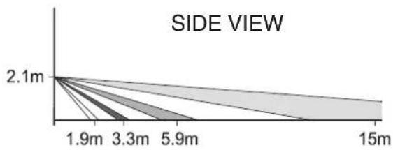
line
| Side View | Value | | --------- | ----- | | 2.1m | 2.1 | | 1.9m | 1.9 | | 3.3m | 3.3 | | 5.9m | 5.9 | | 15m | 15 |
other
| View Side | Range Coverage (m) | | --------- | ------------------ | | Top View | 2.1 | | Minimum | 1.9 | | Range | 3.3 |8. OPERATING MODES
The GW 20 477 detector LEDs indicate the following operating modes:
Green LED = This is activated by pulse frequency signals when movement is detected by the PIR detector. The detections occur in the sensitivity area according to the type of lens used.
When operating, the display is updated every 5 seconds which allows for a rough test of the operating range of the lens being used; for more accurate range tests please refer to the WALK-TEST instructions.
NOTE: The green LED will not switch on when the battery is low.
Red LED = this is activated by pulse frequency signals when transmissions are in progress due to alarm, tamper and surveillance alarms, the low battery status is automatically queued to the first useful transmission.
A fixed light is seen during the stabilising time of 60s during first power-up.
Yellow LED = this is activated by pulse frequency signals when a low battery transmission is sent (red LED).
WALK-TEST = this procedure is useful when accurate testing of the detector activity range is required; the three LED are activated by pulse frequency signals for viewing and alarm transmission during the detector test.
Only the red LED is activated by pulse frequency signals when transmitting tamper status alarms during the WALK-TEST.
To instantly enable/disable the WALK-TEST press the Tamper button after moving the relative switch. The WALK-TEST automatically ends after 10 minutes. The alarm status transmission can be sent at a maximum of every 30 seconds.
9. CODE LEARNING BY THE DETECTOR
A. Open the detector's plastic casing.
B. Check it is powered correctly by removing the battery protection tab.
C. Enter the programme menu on the control unit and go the wireless device learning section.
D. Cause a transmission by pressing and releasing for instance the Tamper button, once the detector code has been memorized proceed to the menu to assign the relative attributes to the device in question.
E. Install the detector in permitted positions, to this purpose please refer to the drawings in the INSTALLATION chapter, and check it to ensure it works correctly with some test transmissions or the WALK-TEST.
F. Close the detector casing checking that the Tamper button is in the correct position.
10. REPLACEMENT AND DISPOSAL OF THE BATTERY
The GW 20 477 detector uses a 3.6V 1.2Ah Lithium battery - ER14250 or LS1425 (1/2AA), and must only be replaced with a new one of the same model.
When loading the battery follow the instructions below carefully:
1) Remove the dead battery.
2) Press and release the TAMPER button 3-4 times to discharge any condensers which may still be charged.
3) Load the new battery.
4) Press and release the TAMPER button 3-4 times.
5) Reset any low battery signals in the control unit or the compatible reception device.
The old batteries must be disposed of according to the laws in force using the specific collection bins.
The disposal of the detector must be implemented in compliance with the laws in force in the country where the system is installed.
The material used in the battery is highly polluting and toxic when dispersed in the environment.
- LAYOUT OF SYSTEM MANAGED BY A GW 20470 CONTROL UNIT

flowchart
graph TD
    A["TX-AM"] --> B["GW 20 473 KEYBOARD for remote control with GW 20 474 KEY"]
    A --> C["GW 20 477 IR TRANSMITTER"]
    A --> D["GW 20 478 TRANSMITTER"]
    A --> E["GW 20 479 TRANSMITTER"]
    A --> F["GW 20 472 REMOTE CONTROL"]
    A --> G["GW 20 483 SMOKE DETECTOR"]
    A --> H["Actuator GW 20 475 for remote signals"]
    A --> I["Max 6 outputs to connect the indicator LEDs"]
    A --> J["GW 1X 861 - GW 1X 866 MOVEMENT DETECTORS"]
    A --> K["GW 1X 862 - GW 1X 867 PUSH-BUTTON PANELS"]
    A --> L["TX-FM"]
    A --> M["TX-FM"]
    A --> N["TX-FM"]
    A --> O["TX-FM"]
    A --> P["TX-FM"]
    A --> Q["TX-FM"]
    A --> R["TX-FM"]
    A --> S["TX-FM"]
    A --> T["TX-FM"]
    A --> U["TX-FM"]
    A --> V["TX-FM"]
    A --> W["TX-FM"]
    A --> X["TX-FM"]
    A --> Y["TX-FM"]
    A --> Z["TX-FM"]
    A --> AA["TX-FM"]
    A --> AB["TX-FM"]
    A --> AC["TX-FM"]
    A --> AD["TX-FM"]
    A --> AE["TX-FM"]
    A --> AF["TX-FM"]
    A --> AG["TX-FM"]
    A --> AH["TX-FM"]
    A --> AI["TX-FM"]
    A --> AJ["TX-FM"]
    A --> AK["TX-FM"]
    A --> AL["TX-FM"]
    A --> AM["TX-FM"]
    A --> AN["TX-FM"]
    A --> AO["TX-FM"]
    A --> AP["TX-FM"]
    A --> AQ["TX-FM"]
    A --> AR["TX-FM"]
    A --> AS["TX-FM"]
    A --> AT["TX-FM"]
    A --> AU["TX-FM"]
    A --> AV["TX-FM"]
    A --> AW["TX-FM"]
    A --> AX["TX-FM"]
    A --> AY["TX-FM"]
    A --> AZ["TX-FM"]
    A --> BA["TX-FM"]
    A --> BB["TX-FM"]
    A --> BC["TX-FM"]
    A --> BD["TX-FM"]
    A --> BE["TX-FM"]
    A --> BF["TX-FM"]
    A --> BG["TX-FM"]
    A --> BH["TX-FM"]
    A --> BI["TX-FM"]
    A --> BJ["TX-FM"]
    A --> BK["TX-FM"]
    A --> BL["TX-FM"]
    A --> BM["TX-FM"]
    A --> BN["TX-FM"]
    A --> BO["TX-FM"]
    A --> BP["TX-FM"]
    A --> BQ["TX-FM"]
The layout shows, as an example, the use of the optional GW 20 480 repeater to transmit the siren command TX signal from a better position in the case where the control unit transmits a critical signal due to architectonic barriers or significant obstructing disturbances.
12. OPERATING EXAMPLES

EXAMPLE 1
Here the control unit is installed on the ground floor, in an off-centre positions, in a three floor building. In this case the various architectonic infrastructures and the lack of "hostile" obstructions allow good transmission signals from most of the sensors and the keyboard towards the control unit, good transmission levels from the control unit towards the actuator but decrease both the self-powered siren command transmission signals and a reception signal from one of the GW 20 477 movement sensors. GW 20 475 system status display module

SOLUTION 1
One option is to move the control unit to a central position on the first floor.
This solution maintains the previous quality of the signals from the sensors and the actuator, and now permits good transmission levels from the control unit towards the self-powered siren and good reception from the GW 20 477 movement sensors, which were previously critical. To make things easier for the user, the position of the keyboard on the ground floor is also moved without creating any signal problems.

SOLUTION 2
It is not possible to move the control unit, but it is possible to change the positions of both the siren and the GW 20 477 sensor.
This solution maintains the previous quality of the signals from the sensors and the actuator and now permits good transmission levels from the control unit towards the self-powered siren, whilst the transmission signal from the GW 20 477 movement sensor remains critical. GW 20 475 system status display module.

flowchart
graph TD
    A[" signals Range of the GW 20 480 REPEATER "] --> B[" GW 20 477 "]
    A --> C[" GW 20 473 KEYBOARD "]
    A --> D[" GW 20 478 "]
    A --> E[" GW 20 480 NOT RX "]
    A --> F[" GOOD SIGNALS "]
    A --> G[" GOOD SIGNALS "]
    A --> H[" GOOD SIGNALS "]
    A --> I[" GOOD SIGNALS "]
    A --> J[" GOOD SIGNALS "]
    A --> K[" GOOD SIGNALS "]
    A --> L[" GOOD SIGNALS "]
    A --> M[" GOOD SIGNALS "]
    A --> N[" GOOD SIGNALS "]
    A --> O[" GOOD SIGNALS "]
    A --> P[" GOOD SIGNALS "]
    A --> Q[" GOOD SIGNALS "]
    A --> R[" GOOD SIGNALS "]
    A --> S[" GOOD SIGNALS "]
    A --> T[" GOOD SIGNALS "]
    A --> U[" GOOD SIGNALS "]
    A --> V[" GOOD SIGNALS "]
    A --> W[" GOOD SIGNALS "]
    A --> X[" GOOD SIGNALS "]
    A --> Y[" GOOD SIGNALS "]
    A --> Z[" GOOD SIGNALS "]
    A --> AA[" GOOD SIGNALS "]
    A --> AB[" GOOD SIGNALS "]
    A --> AC[" GOOD SIGNALS "]
    A --> AD[" GOOD SIGNALS "]
    A --> AE[" GOOD SIGNALS "]
    A --> AF[" GOOD SIGNALS "]
    A --> AG[" GOOD SIGNALS "]
    A --> AH[" GOOD SIGNALS "]
    A --> AI[" GOOD SIGNALS "]
    A --> AJ[" GOOD SIGNALS "]
    A --> AK[" GOOD SIGNALS "]
    A --> AL[" GOOD SIGNALS "]
    A --> AM[" GOOD SIGNALS "]
    A --> AN[" GOOD SIGNALS "]
    A --> AO[" GOOD SIGNALS "]
    A --> AP[" GOOD SIGNALS "]
    A --> AQ[" GOOD SIGNALS "]
    A --> AR[" GOOD SIGNALS "]
    A --> AS[" GOOD SIGNALS "]
    A --> AT[" GOOD SIGNALS "]
    A --> AU[" GOOD SIGNALS "]
    A --> AV[" GOOD SIGNALS "]
    A --> AW[" GOOD SIGNALS "]
    A --> AX[" GOOD SIGNALS "]
    A --> AY[" GOOD SIGNALS "]
    A --> AZ[" GOOD SIGNALS "]
    A --> BA[" GOOD SIGNALS "]
    A --> BB[" GOOD SIGNALS "]
    A --> BC[" GOOD SIGNALS "]
    A --> BD[" GOOD SIGNALS "]
    A --> BE[" GOOD SIGNALS "]
    A --> BF[" GOOD SIGNALS "]
    A --> BG[" GOOD SIGNALS "]
    A --> BH[" GOOD SIGNALS "]
    A --> BI[" GOOD SIGNALS "]
    A --> BJ[" GOOD SIGNALS "]
    A --> BK[" GOOD SIGNALS "]
    A --> BL[" GOOD SIGNALS "]
    A --> BM[" GOOD SIGNALS "]
    A --> BN[" GOOD SIGNALS "]
    A --> BO[" GOOD SIGNALS "]
    A --> BP[" GOOD SIGNALS "]
    A --> BQ[" GOOD SIGNALS "]
    A --> BR[" GOOD SIGNALS "]
    A --> BS[" GOOD SIGNALS "]
    A --> BT[" GOOD SIGNALS "]
    A --> BU[" GOOD SIGNALS "]
    A --> BV[" GOOD SIGNALS "]
    A --> BW[" GOOD SIGNALS "]
    A --> BX[" GOOD SIGNALS "]
    A --> BY[" GOOD SIGNALS "]
    A --> BZ[" GOOD SIGNALS "]
    A --> CA[" GOOD SIGNALS "]
    A --> CB[" GOOD SIGNALS "]
    A --> CC[" GOOD SIGNALS "]
    A --> CD[" GOOD SIGNALS "]
    A --> CE[" GOOD SIGNALS "]
    A --> CF[" GOOD SIGNALS "]
    A --> CG[" GOOD SIGNALS "]
    A --> CH[" GOOD SIGNALS "]
    A --> CI[" GOOD SIGNALS "]
    A --> CJ[" GOOD SIGNALS "]
    A --> CK[" GOOD SIGNALS "]
    A --> CL[" GOOD SIGNALS "]
    A --> CM[" GOOD SIGNALS "]
    A --> CN[" GOOD SIGNALS "]
    A --> CO[" GOOD SIGNALS "]
    A --> CP[" GOOD SIGNALS "]
    A --> CQ[" GOOD SIGNALS "]
    A --> CR[" GOOD SIGNALS "]
    A --> CS[" GOOD SIGNALS "]
    A --> CT[" GOOD SIGNALS "]
    A --> CU[" GOOD SIGNALS "]
    A --> CV[" GOOD SIGNALS "]
    A --> CW[" GOOD SIGNALS "]
    A --> CX[" GOOD SIGNALS "]
    A --> CY[" GOOD SIGNALS "]
    A --> CZ[" GOOD SIGNALS "]
SOLUTION 3
This option uses a GW 20 480 type TX and RX repeater to be installed in the best possible position and connected by cable to the control unit.
In this case the GW 20 480 repeater extends the control unit TX and RX signals, it automatically excludes the functions of the control unit RX circuit and becomes the convergence point for all the transmission and reception signals. Adopting this solution it is possible to return to the original installation layout of the various devices as they all now transmit and receive good signals.
AVERTISSEMENTS
POUR L'INSTALLATEUR:
Moving the microswitch lever to install the sensor in a corner:
line
| Distance | Value | | -------- | ----- | | 2.1m | | | 1.9m | | | 3.3m | | | 5.9m | | | 15m | |
line
| Distance (m) | Value | | ------------ | ----- | | 0 | 2.1 | | 1.9 | 1.9 | | 3.3 | 3.3 |8. FONCTIONNEMENT
line
| Distance (m) | Capacity (m) | | ------------ | ------------ | | 0 | 2.1 | | 1.9 | 3.3 |8. OPERATIVIDAD


- AVVERTENZE
- PER L'INSTALLATORE:
- OPERATIVITA'
- FOR THE OPERATOR:
- Passive infrared detector for wireless burglar alarm systems using GW 20 470 and GW 20 481 control units
- GENERAL INFORMATION
- INSTALLATION
- FIRST POWER-UP PROCEDURE
- TAMPER PROTECTION ON THE BASE
- RANGE OF COVERAGE DRAWINGS
- Standard lens
- OPERATING MODES
- CODE LEARNING BY THE DETECTOR
- REPLACEMENT AND DISPOSAL OF THE BATTERY
- OPERATING EXAMPLES
- EXAMPLE 1
- SOLUTION 1
- SOLUTION 2
- SOLUTION 3
- AVERTISSEMENTS
- POUR L'INSTALLATEUR:
- FONCTIONNEMENT
- OPERATIVIDAD
Brand : Gewiss
Model : GW20477
Category : Motion detector