
iCSPTP2T02 - Flat screen mount Chief - Free user manual and instructions
Find the device manual for free iCSPTP2T02 Chief in PDF.

| Product Type | Flat panel wall mount |
| Brand | Chief |
| Model | iCSPTP2T02 |
| Maximum Load Capacity | 18 kg (40 lb) |
| VESA Compatibility | 75x75, 100x100, 100x200, 200x100 mm |
| Materials | Steel |
| Wall Fixing | On wood stud (screws provided) |
| Adjustments | Tilt, swivel, roll (via knob and hex screw) |
| Installation Type | Fixed, with height adjustment option (3 positions) |
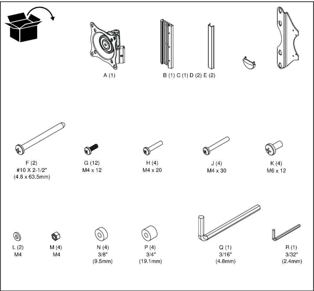
| Package Contents | Wall plate, head block, sheath, tip, brackets (E), spacers (N, P), screws (G, H, J, K), washers (L), nuts (M), hex keys (Q, R) |
| Orientation | Landscape or portrait depending on adjustment |
| Cleaning | Soft dry cloth, avoid abrasive products |
| Safety | Do not exceed load capacity; ensure structure supports 5 times total weight |
| Repairability | Spare parts available from manufacturer; screw tightening adjustable |
Frequently Asked Questions - iCSPTP2T02 Chief
User questions about iCSPTP2T02 Chief
0 question about this device. Answer the ones you know or ask your own.
Ask a new question about this device
Download the instructions for your Flat screen mount in PDF format for free! Find your manual iCSPTP2T02 - Chief and take your electronic device back in hand. On this page are published all the documents necessary for the use of your device. iCSPTP2T02 by Chief.
USER MANUAL iCSPTP2T02 Chief
natural_image
Technical line drawing of a mechanical component with mounting flanges and central spiral feature (no text or symbols)DISCLAIMER
CSAV, Inc., and its affiliated corporations and subsidiaries (collectively, "CSAV"), intend to make this manual accurate and complete. However, CSAV makes no claim that the information contained herein covers all details, conditions or variations, nor does it provide for every possible contingency in connection with the installation or use of this product. The information contained in this document is subject to change without notice or obligation of any kind. CSAV makes no representation of warranty, expressed or implied, regarding the information contained herein. CSAV assumes no responsibility for accuracy, completeness or sufficiency of the information contained in this document.

IMPORTANT WARNINGS AND CAUTIONS!
WARNING: A WARNING alerts you to the possibility of serious injury or death if you do not follow the instructions.

CAUTION: A CAUTION alerts you to the possibility of damage or destruction of equipment if you do not follow the corresponding instructions.

WARNING: Failure to read, thoroughly understand, and follow all instructions can result in serious personal injury, damage to equipment, or voiding of factory warranty! It is the installer's responsibility to make sure all components are properly assembled and installed using the instructions provided.

WARNING: Failure to provide adequate structural strength for this component can result in serious personal injury or damage to equipment! It is the installer's responsibility to make sure the structure to which this component is attached can support five times the combined weight of all equipment. Reinforce the structure as required before installing the component.

WARNING: Exceeding the weight capacity can result in serious personal injury or damage to equipment! It is the installer's responsibility to make sure the combined weight of all components attached to the iCSPTP2 does not exceed 40 lbs (18kg).

PARTS
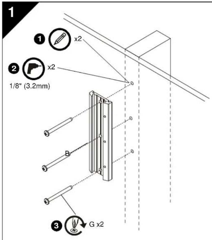
INSTALL WALL PLATE TO WALL
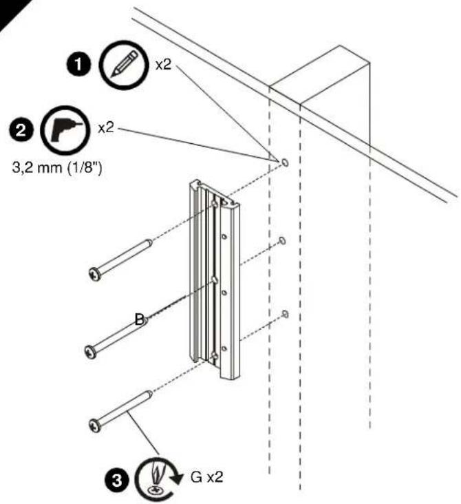
Wood Stud Installation

WARNING: Failure to provide adequate structural strength for this component can result in serious personal injury or damage to equipment! It is the installer's responsibility to make sure the structure to which this component is attached can support five times the combined weight of all equipment. Reinforce the structure as required before installing the component.
- Level wall plate (B) and mark locations of pilot holes.
- Drill 1/8" (3.2mm) diameter pilot holes into wood stud.
- Install screws (G) through wall plate (B) into wood stud.
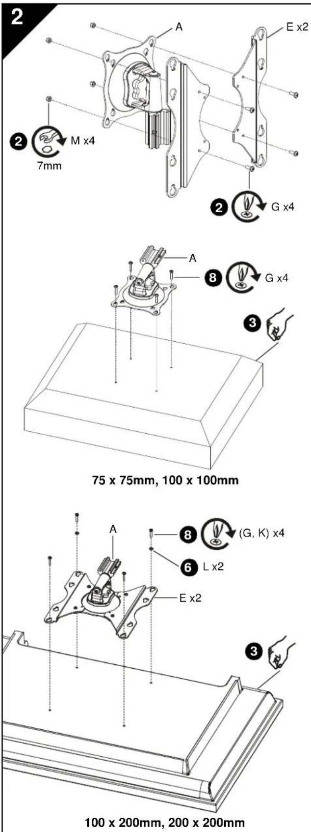
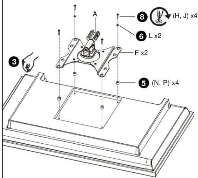
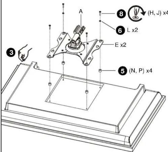
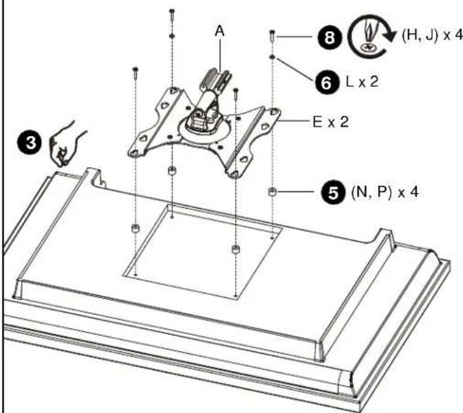
INSTALL HEAD ASSEMBLY TO DISPLAY

WARNING: Exceeding the weight capacity can result in serious personal injury or damage to equipment! It is the installer's responsibility to make sure the combined weight of all components attached to the iCSPTP2 does not exceed 40 lbs (18 kg).
-
Proceed as follows:
-
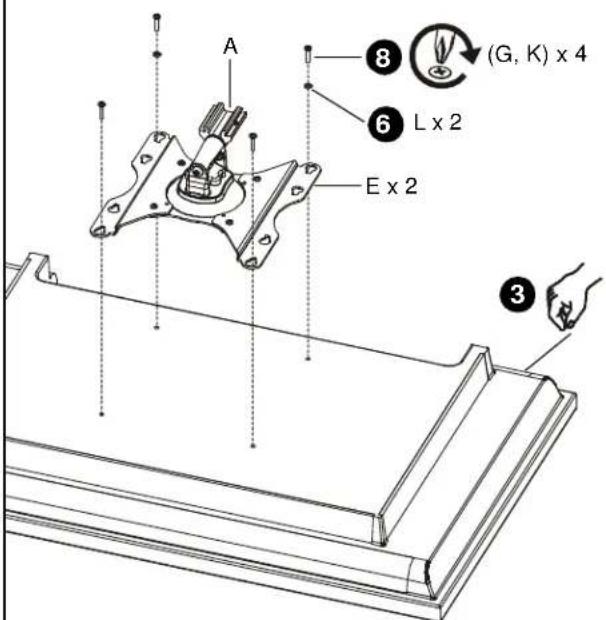
If display has a 100 x 200mm or 200 x 200mm mounting hole pattern, then proceed to Step 2 below and see figure at bottom left.
-
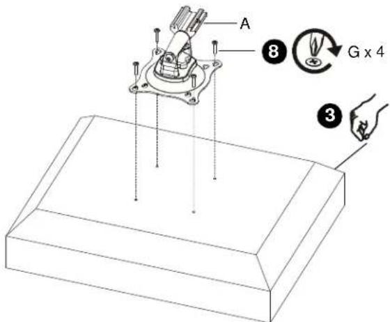
If display has a 75 x 75mm or 100 x 100mm mounting hole pattern, then proceed to Step 3 below. (See figure at middle left)
-
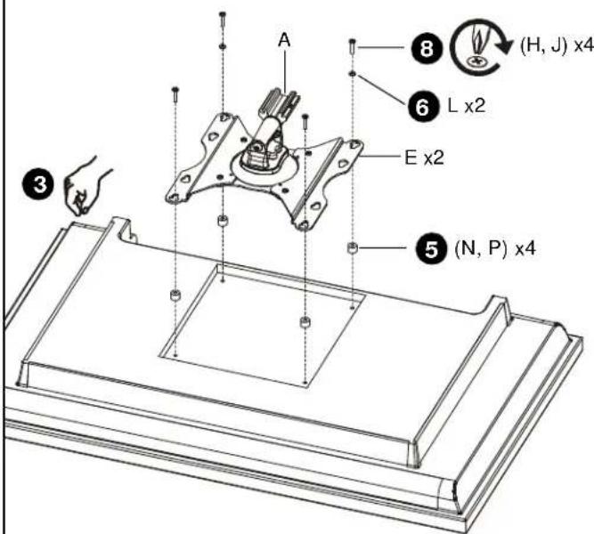
Install screws (G) through brackets (E) and head assembly (A) into nuts (M). (See figure at top left)
- Carefully place display face down on protective surface.
- Proceed as follows:
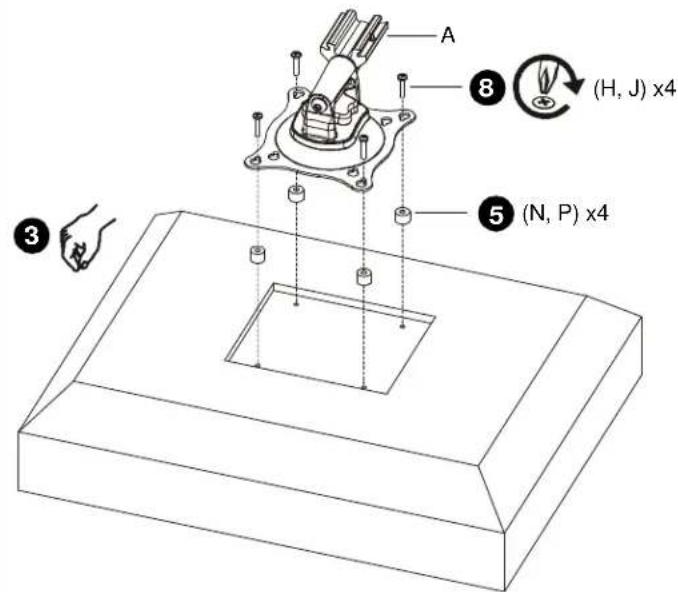
• If mounting holes are recessed into back surface of display, then proceed to Step 5 below.
• If mounting holes are flush with back surface of display, then proceed to Step 6 below.
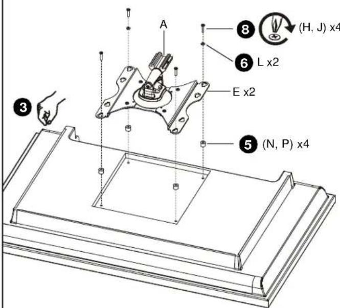
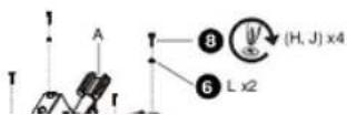
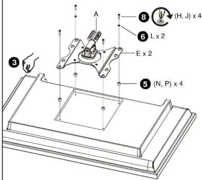
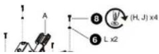
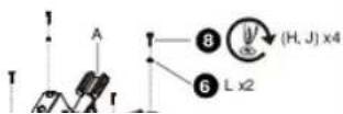
- Place four spacers (N or P, as applicable) over each mounting hole on back of display. Select shortest spacer which will provide adequate fill. All spacers must be same length.
-
Select screw length:
-
For flush mounting holes use screws (G) or (K), as applicable.
- If using spacers (N), then use screws (H).
-
If using spacers (P), then use screws (J).
-
Orient head assembly (A) so that teardrop mounting holes are aligned with holes in display or holes in spacers (N, P), as applicable.
2
75 x 75mm, 100 x 100mm
100 x 200mm, 200 x 200mm
INSTALL HEAD ASSEMBLY TO DISPLAY (Continued)

CAUTION: Using screws of improper size may damage your display! Proper screws will easily and completely thread into display mounting holes.
- Install selected screws through washers (L, if applicable), teardrop mounting holes, and spacers (N or P, if applicable) into display.
- If installing 4mm diameter screws (G, H, or J) through brackets (E), then also use washers (L) for lower pair of teardrop mounting holes.
- Tighten all four screws. Do not overtighten!
3
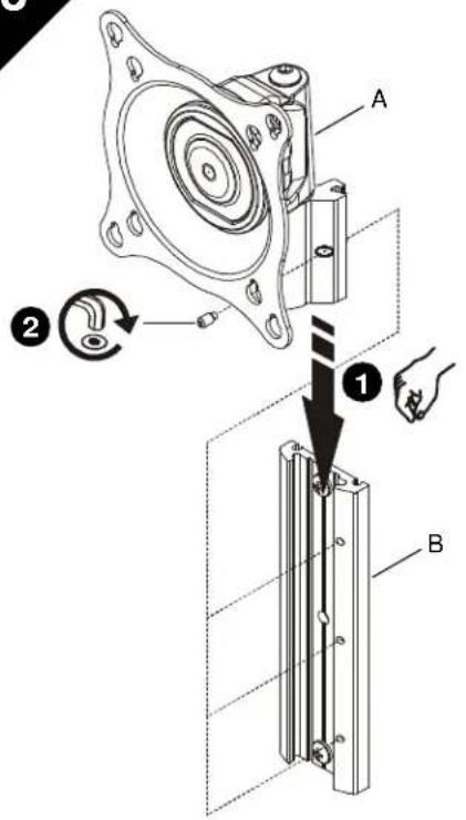
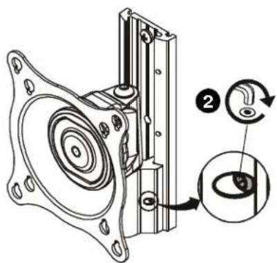
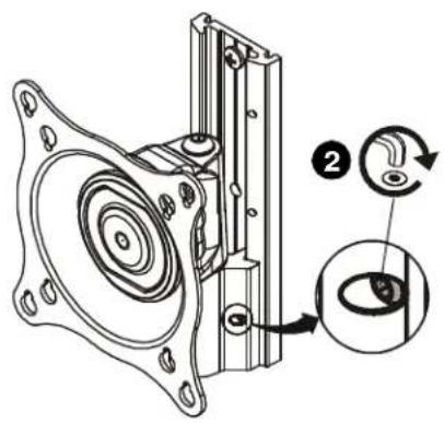
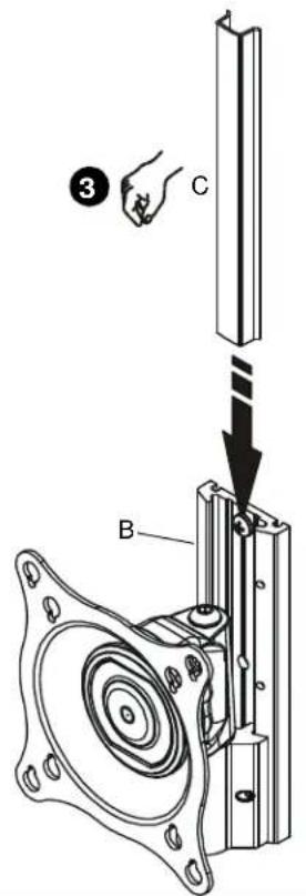
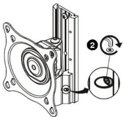
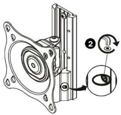
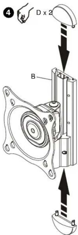
INSTALL HEAD ASSEMBLY TO WALL PLATE
- Align head assembly (A) with wall plate (B) and slide into position.
NOTE: Display not shown for clarity.

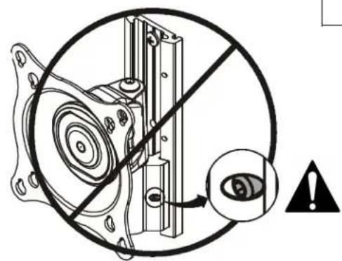
WARNING: Failure to align hex head screw with hole in wall plate (B) may allow head assembly (A) to fall, resulting in serious personal injury or damage to equipment! Hex head screw should fully recede into head assembly hole after tightening.
- Using hex key (R), tighten hex head screw in head assembly (A) ensuring that screw engages one of three holes in wall plate (B).
NOTE: Three holes are provided in wall plate (B) to provide height adjustment.
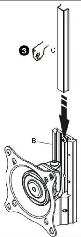
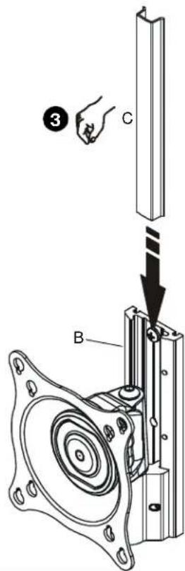
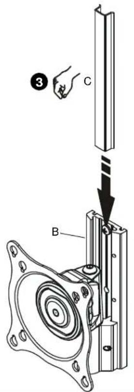
-
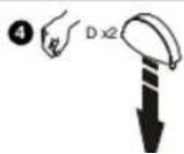
Align cover (C) with grooves in wall plate (B) and slide into position.
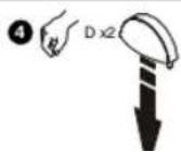
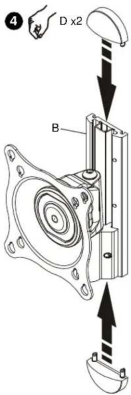
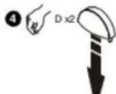
-
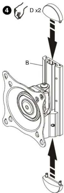
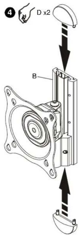
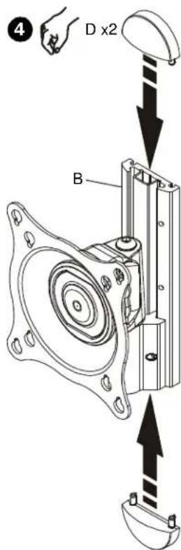
Align caps (D) with holes in wall plate (B) and slide into position.


4
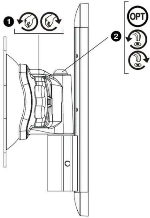
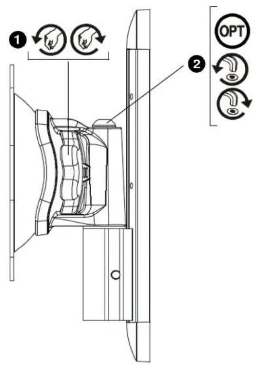
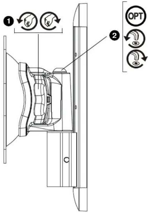
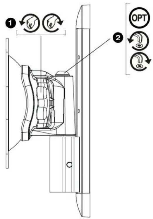
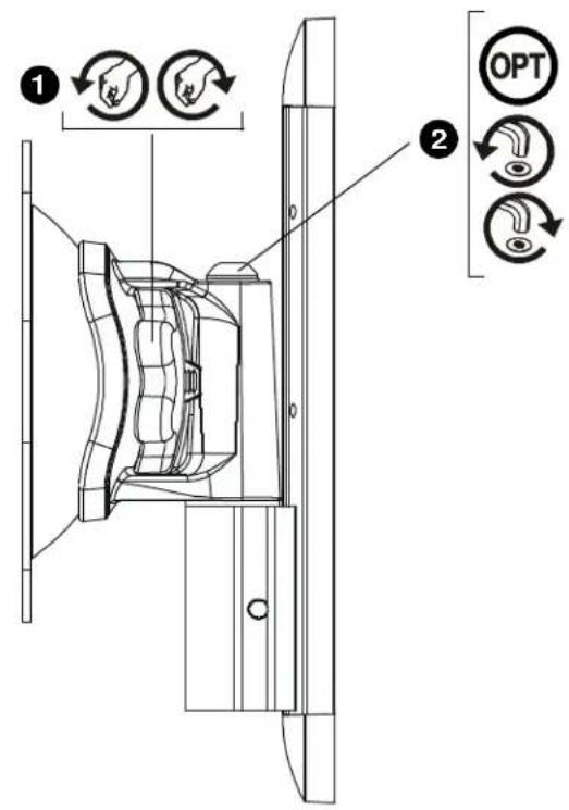
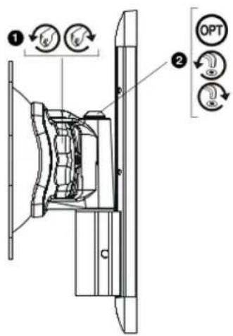
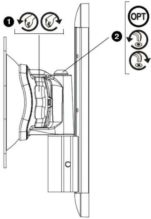
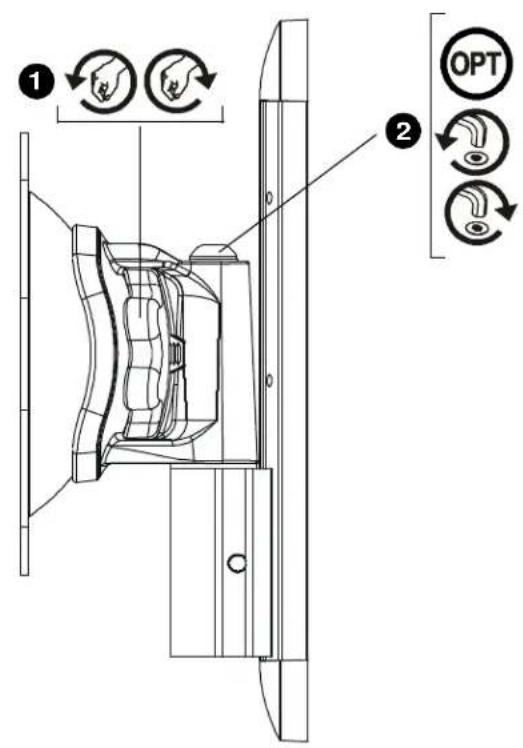
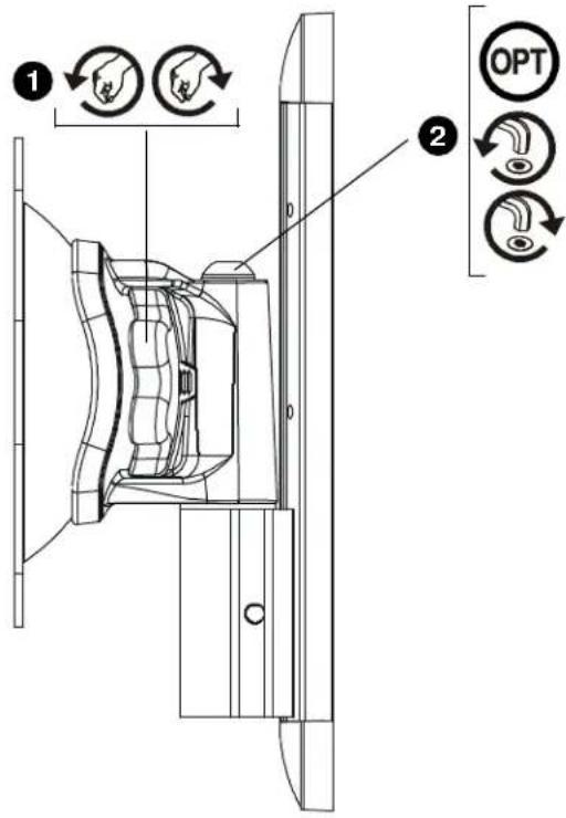
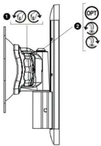
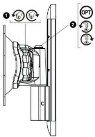
ADJUSTMENT

WARNING: Excessive loosening or tightening of adjustment mechanism can result in serious personal injury or damage to equipment!
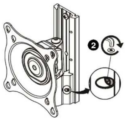
- To adjust pitch/swivel/roll, slightly loosen adjustment knob (counterclockwise when looking at back of display), move display to desired angle, and retighten adjustment knob.
- OPTIONAL: Additional swivel adjustment may be made by slightly loosening or tightening adjustment screw using hex key (Q). Adjust screws ONLY as required to achieve desired tension.
1
75 x 75 mm, 100 x 100 mm
100 x 200 mm, 200 x 200 mm


4
AJUSTE

75 x 75 mm, 100 x 100 mm

100 x 200 mm, 200 x 200 mm
EINBAU DER KOPFBAUGRUPPE AM DISPLAY (Forts.)

EINBAU DER KOPFBAUGRUPPE AN WANDPLATTE

4
EINSTELLUNG

INSTALAR A PLACA NA PAREDE
75 x 75 mm, 100 x 100 mm
100 x 200 mm, 200 x 200 mm
INSTALAR A UNIDADE DA CABEÇA NA PLACA DE PAREDE


4
AJUSTE

INSTALLAZIONE DELLA PIASTRA A PARETE SULLA PARETE
75 x 75 mm, 100 x 100 mm
100 x 200 mm, 200 x 200 mm
INSTALLAZIONE DEL BLOCCO TESTA SUL DISPLAY (segue)

INSTALLAZIONE DEL BLOCCO TESTA SULLA PIASTRA A PARETE

4

REGOLAZIONE

WANDPLAAT AAN WAND BEVESTIGEN
75 x 75 mm, 100 x 100 mm

100 x 200 mm, 200 x 200 mm
KOPCONSTRUCTIE AAN WANDPLAAT BEVESTIGEN
4
AFSTELLEN

75 x 75 mm, 100 x 100 mm

100 x 200 mm, 200 x 200 mm
INSTALLER LE BLOC-TÊTES SUR L'AFFICHAGE (Suite)

INSTALLER LE BLOC-TÊTES SUR LA PLAQUE MURALE


4

RÉGLAGE

natural_image
Mechanical assembly diagram showing gears and shafts without any text or symbols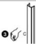
4
РЕГУЛИРОВКА

MONTERING AF VÆGPLADE PÅ VÆG
75 x 75 mm, 100 x 100 mm

100 x 200 mm, 200 x 200 mm
MONTERING AF HOVEDENHED TIL SKÆRM (Fortsat)

MONTERING AF HOVEDENHED PÅ VÆGPLADE
4
JUSTERING

MONTERA VÄGGPLATTAN PÅ VÄGGEN
75 x 75 mm, 100 x 100 mm
100 x 200 mm, 200 x 200 mm
MONTERA HUVUDENHETEN PÅ VÄGGPLATTAN


4
JUSTERING

75 x 75 mm, 100 x 100 mm
100 x 200 mm, 200 x 200 mm
KANNATINPÄÄN ASENTAMINEN NÄYTTÖÖN

75 x 75 mm, 100 x 100 mm
100 x 200 mm, 200 x 200 mm
KANNATINPÄÄN ASENTAMINEN NÄYTTÖÖN (Jatkoa)

KANNAKEPÄÄN ASENTAMINEN SEINÄLEVYYN


4
ASENNON SÄÄTÄMINEN

MONTOWANIE ZESPOŁU GŁOWICY DO WYŚWIETLACZA

75 x 75 mm, 100 x 100 mm
MONTOWANIE ZESPOŁU GŁOWICY DO WYŚWIETLACZA (cd.)

MONTOWANIE ZESPOŁU GŁOWICY DO PŁYTY ŚCIENNEJ
natural_image
Mechanical assembly diagram showing gear and shaft components (no text or labels)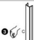
4
REGULACJA

ΠΡΟΣΑΡΜΟΓΗ

KAFA DÜZENEĞİNİ EKRANA MONTE ETME

KAFA DÜZENEĞİNİ EKRANA MONTE ETME (Devam)

KAFA DÜZENEĞİNİ DUVAR PLAKASINA MONTE ETME

natural_image
Mechanical assembly diagram showing a gear and shaft assembly (no text or labels)
4
AYARLAMA

A FEJ FELSZERELÉSE A KIJELZÖRE

BEÁLLÍTÁS

Installation Instructions iCSPTP2

Manufactured by CHIEF®
iC Mounting Solutions
USA · 8401 Eagle Creek Parkway, Suite 700 · Savage, Minnesota 55378 · 800.572.1373
Europe/Middle East/Africa · +31 (0)40 2668620
www.icmounts.com
©2007 Chief Manufacturing Inc. The iC Logo and StowAway are trademarks of Chief Manufacturing Inc. All rights reserved
Patents and patents pending. Chief Manufacturing Inc. Savage, MN 55378, USA
12/07
8805-000189 RevB