iCSPSA2T02 - Flat screen mount Chief - Free user manual and instructions
Find the device manual for free iCSPSA2T02 Chief in PDF.

| Brand | Chief |
| Model | iCSPSA2T02 |
| Product Type | Flat panel mount |
| Maximum Supported Weight | 18 kg (40 lbs) |
| Material | Steel |
| Compatible VESA Standard | 75×75 mm, 100×100 mm, 100×200 mm, 200×200 mm |
| Height Adjustment | Yes, via 3 positions on the wall plate |
| Mounting Type | Wall mounting on wood stud or concrete |
| Tilt | Not specified |
| Rotation | Not specified |
| Package Contents | Arm (A), wall plate (B), cover (C), tip (D), fixing brackets (F), spacers (N, P), screws (J, K), washers (L), hex key (T) |
| Maintenance | Clean with a soft, dry cloth |
| Safety Precautions | Do not exceed maximum load; use appropriate screws; tighten without excess |
| Support | Multilingual manual available for free download |
Frequently Asked Questions - iCSPSA2T02 Chief
User questions about iCSPSA2T02 Chief
0 question about this device. Answer the ones you know or ask your own.
Ask a new question about this device
Download the instructions for your Flat screen mount in PDF format for free! Find your manual iCSPSA2T02 - Chief and take your electronic device back in hand. On this page are published all the documents necessary for the use of your device. iCSPSA2T02 by Chief.
USER MANUAL iCSPSA2T02 Chief
Milestone AV Technologies, and its affiliated corporations and subsidiaries (collectively, "Milestone"), intend to make this manual accurate and complete. However, Milestone makes no claim that the information contained herein covers all details, conditions or variations, nor does it provide for every possible contingency in connection with the installation or use of this product. The information contained in this document is subject to change without notice or obligation of any kind. Milestone makes no representation of warranty, expressed or implied, regarding the information contained herein. Milestone assumes no responsibility for accuracy, completeness or sufficiency of the information contained in this document.
Chief® and Centris™ are trademarks of Milestone AV Technologies. All rights reserved.

IMPORTANT WARNINGS AND CAUTIONS!

WARNING: A WARNING alerts you to the possibility of serious injury or death if you do not follow the instructions.

CAUTION: A CAUTION alerts you to the possibility of damage or destruction of equipment if you do not follow the corresponding instructions.

WARNING: Failure to read, thoroughly understand, and follow all instructions can result in serious personal injury, damage to equipment, or voiding of factory warranty! It is the installer's responsibility to make sure all components are properly assembled and installed using the instructions provided.

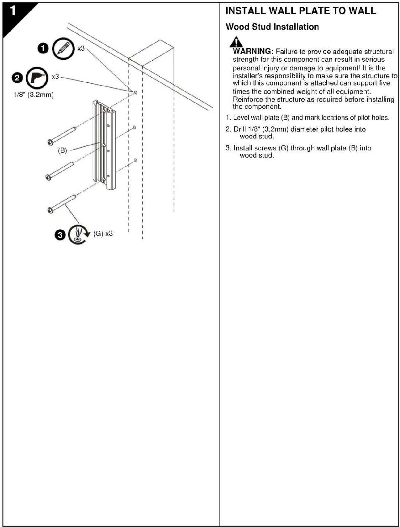
WARNING: Failure to provide adequate structural strength for this component can result in serious personal injury or damage to equipment! It is the installer's responsibility to make sure the structure to which this component is attached can support five times the combined weight of all equipment. Reinforce the structure as required before installing the component. The wall to which the mount is being attached may have a maximum drywall thickness of 5/8'' (15.9mm).

WARNING: Exceeding the weight capacity can result in serious personal injury or damage to equipment! It is the installer's responsibility to make sure the combined weight of all components attached to the iCSPSA2 does not exceed 40 lbs (18kg). Use with products heavier than the maximum weight indicated may result in collapse of the mount and its accessories causing possible injury.

AVISOS Y PRECAUCIONES IMPORANTES!

Installation Instructions
#
BAXHBIE INPEDYNPEXDEHIN IN PEPDOCTEPEXEHN
A
PNEQYIPXEDEHME. npraaqdt B rotohoctb Bac K BOBMAKHOCTeep3bHO PAHU cMePTn,ecnBHe CHeDyTe 3a HcHtpykAHI
4
BHIMAHWE: npmbodnB a roTOBbCTB Bac K BO3MOXOCHN nOBePekDnE mI p4a2yHeHb OoOpydoBaHb, eCm Bn He chcyeTe 3aooTETBtYIOuMm INHCTpKUHm.
A
NPDEYPKEEHNEO.OTK3AHTATB,YY06NIOFOHCTbNO HONRTB,NCTE2OB3TBA B0MAVNHCTpykMMAOKET NPAEIEK T KOEPAHOM TYEOCHMO NPOPEKDEHNO NPOPEKDEHNO OBOOPDyABHANIKI,UMOBO6OeDHNO 4a0pHHoRAPAHNTI 1TO-OTBE7CBHEHOCTb MOCTAHKKHA 9QDCOTEBPPVTCA, YTO BO KOMNHOENTHb DDTGIMOBp3AM 0c0paHn yYCTAHAAHn PHNOCbOBAHne NPDEOZABHNNHxNCTpykN

VIGTIG ADVARSLER OG FORHOLDSREGLER!

Installation Instructions
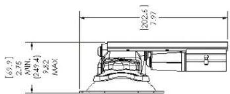
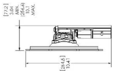
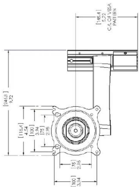
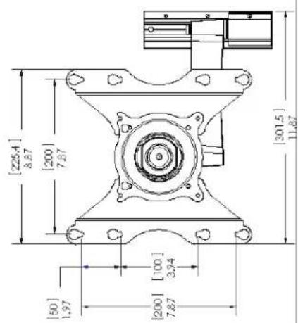
DIMENSIONS
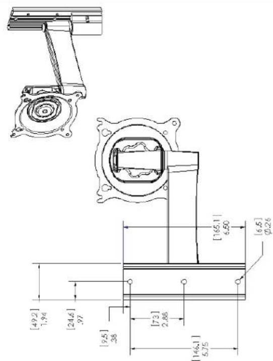
FLAT PANEL MOUNTING PATTERN INFORMATION VESA:75x75mm,100x100mm, 200x100mm,200x200mm

2
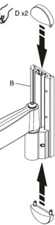
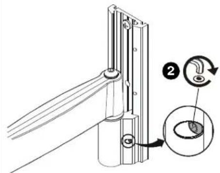
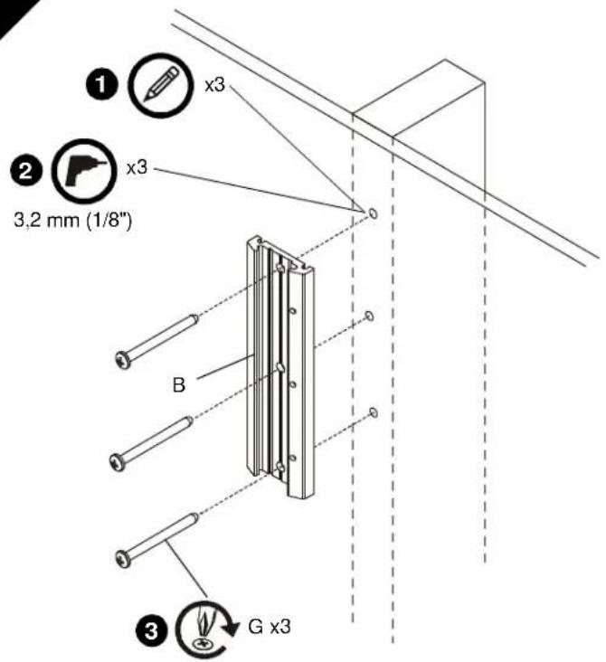
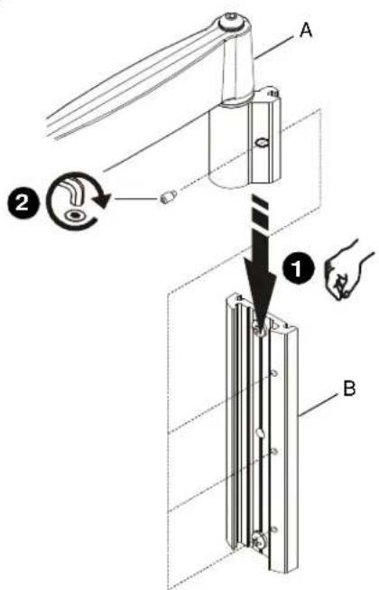
INSTALL ARM ASSEMBLY TO WALL PLATE
IMPORTANT! If installing a display with recessed mounting holes, then proceed to "INSTALL DISPLAY TO ARM ASSEMBLY" before installing arm assembly to wall plate.
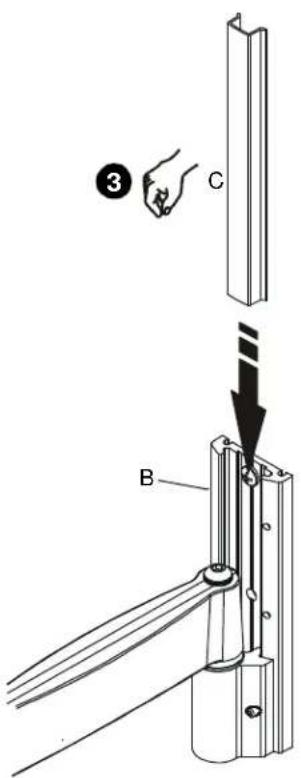
- Align arm assembly (A) with wall plate (B) and slide into position.
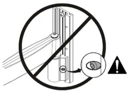
WARNING: Failure to align hex head screw with hole in wall plate (B) may allow arm assembly (A) to fall, resulting in serious personal injury or damage to equipment! Hex head screw should fully recede into arm assembly hole after tightening. - Using hex key (T), tighten hex head screw in arm assembly (A) ensuring that screw engages one of three holes in wall plate (B).
NOTE: Three holes are provided in wall plate (B) to provide height adjustment.
- Align cover (C) with grooves in wall plate (B) and slide into position.
- Align caps (D) with holes in wall plate (B) and slide into position.
3
4
3B

Recessed Mounting Holes
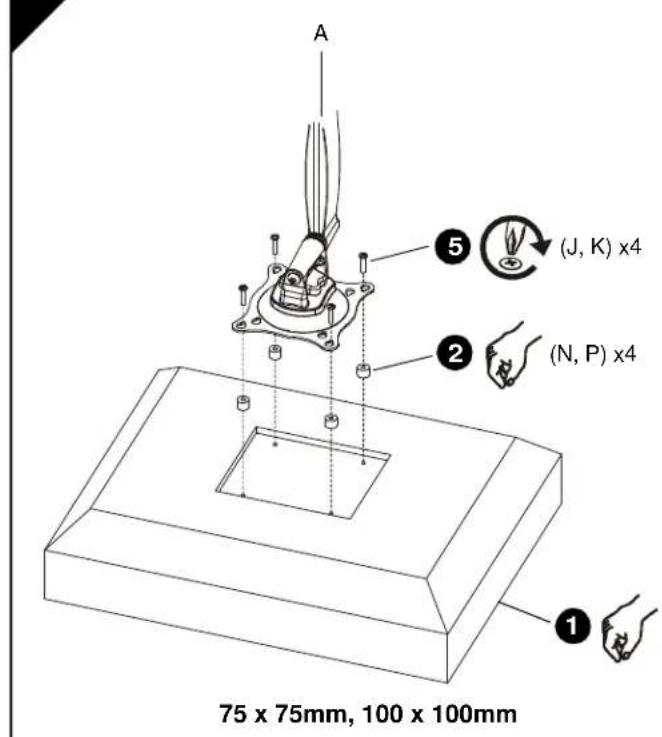
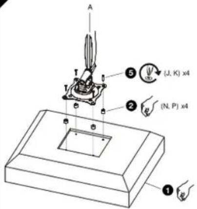
IMPORTANT! This procedure only applicable when 4mm diameter mounting holes are recessed into back surface of display.

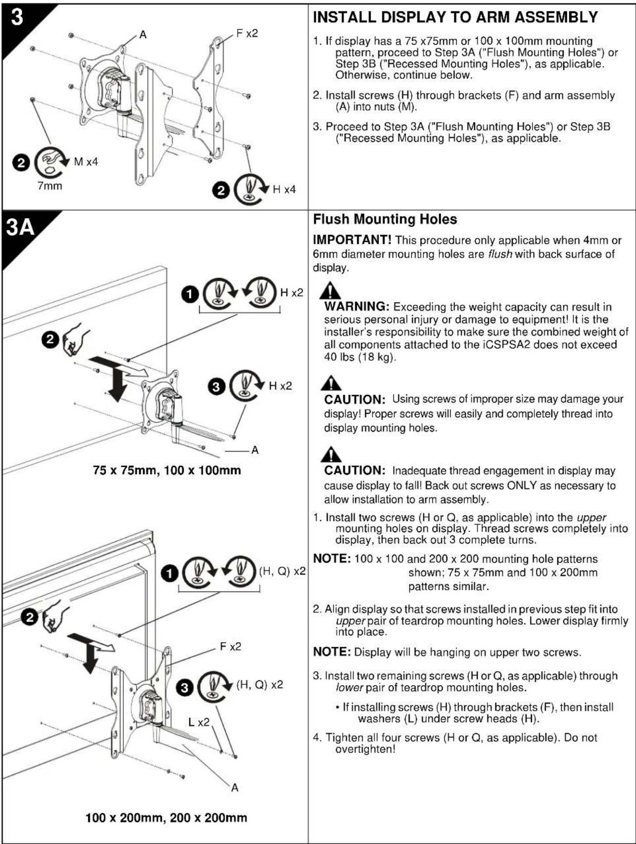
WARNING: Exceeding the weight capacity can result in serious personal injury or damage to equipment! It is the installer's responsibility to make sure the combined weight of all components attached to the iCSPSA2 does not exceed 40 lbs (18 kg).
- Carefully place display face down on protective surface.
- Place four spacers (N or P, as applicable) over each mounting hole on back of display. Select shortest spacer which will provide adequate fill. All spacers must be same length.
NOTE: 100 × 100 and 200 × 200 mounting hole patterns shown; 75 × 75mm and 100 × 200mm patterns similar.
- Select screw length:
If using spacers (N), then use screws (J).
If using spacers (P), then use screws (K).
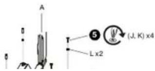
NOTE: If installing screws (J, K) through brackets (F), then also use washers (L) for lower pair of teardrop mounting holes.
- Orient arm assembly (A) so that teardrop mounting holes are aligned with holes in spacers (N or P, as applicable).

CAUTION: Using screws of improper size may damage your display! Proper screws will easily and completely thread into display mounting holes.
- Install screws (J or K, as applicable) through washers (L, if applicable), teardrop mounting holes, and spacers (N or P, as applicable), into display. Tighten all four screws. Do not overtighten!
- Continue with "INSTALL ARM ASSEMBLY TO WALL PLATE."
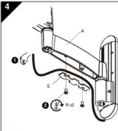
| 4 1 2 3 | CABLE MANAGEMENT CAUTION: Ensure that adequate cable slack exists for movement of display, and that cables will not be pinched by installation of cover (E) or screws (R). 1. Carefully insert cables into cavity located in lower portion of arm assembly (A). 2. Install cover (E) with two screws (R). |
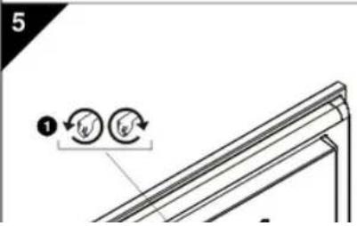
| 5 1 2 3 | ADJUSTMENT WARNING: Excessive loosening or tightening of adjustment mechanism can result in serious personal injury or damage to equipment! 1. To adjust pitch/swivel/roll, slightly loosen adjustment knob (counterclockwise when looking at back of display), move display to desired angle, and retighten adjustment knob. 2. To adjust extension, slightly loosen or tighten adjustment screws using hex key (S). Adjust screws ONLY as required to achieve desired tension. |
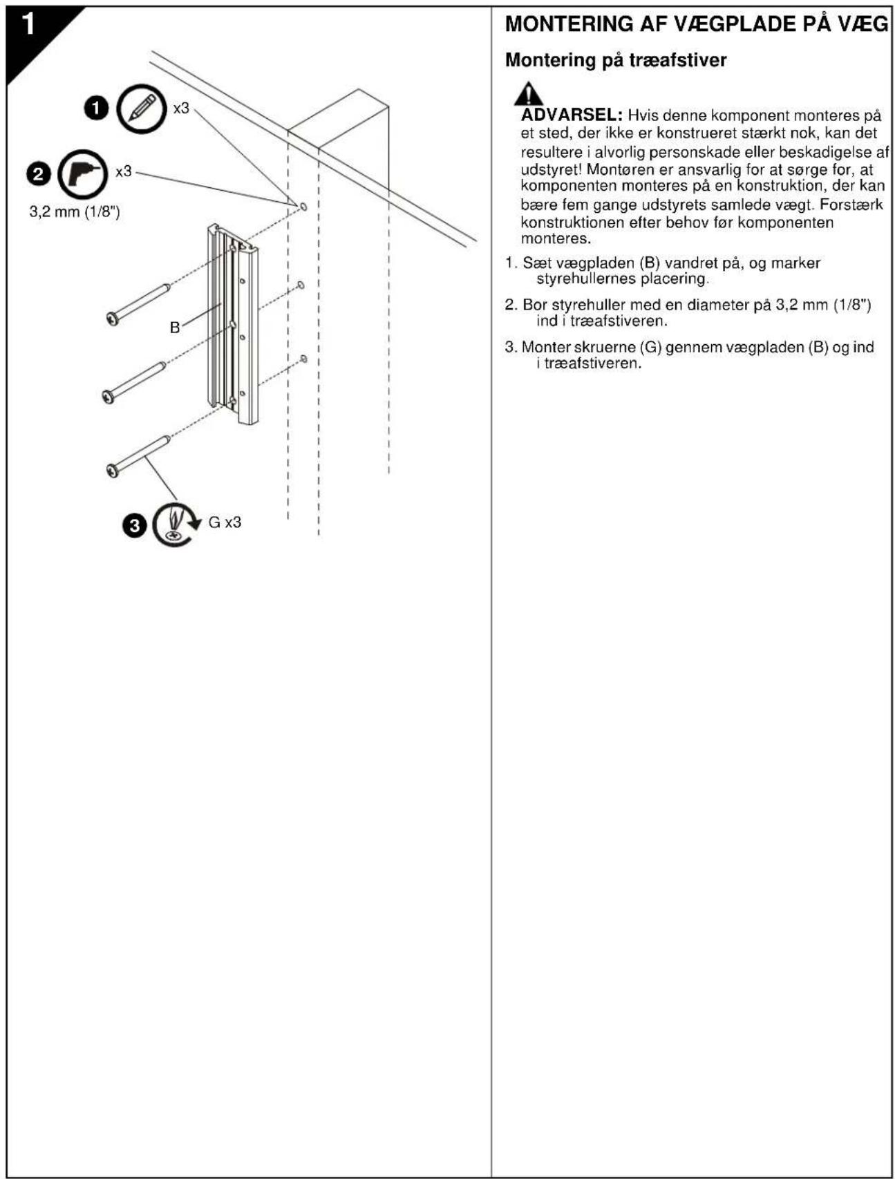
1
INSTALACION DE LA PLACA DE MONTAJE EN PARED
WANDPLAAT AAN WAND BEVESTIGEN
ARMCONSTRUCTIE AAN WANDPLAAT BEVESTIGEN
BHMAHME: Pn HmnoBtBAMn BnKTOB HnOeDQaRbRaP3MaPeB 0oMxHOoNpOBeXepEeBc
dncnneBnBnTu npBaBnHoRoP3MaPeN noNoNcoCTb
BnBBHnAeBnBnBnBnBnBnBnBnBnBnBnBnBnBnBnBnBnBnBnBnBnBnBnBnBnBnBnBnBnBnBnBnBnBnBnBnBnBnBnBnBnBnBnBnBnBnBnBnBnBnB
3B
75×75MM,100×100MM
3ayn6nHHbIe KpenexKbIe OTBepCTH
BAKHO!Ira npoeaepya npnHEMHa TOLbKO e cRNI KxepKHeB OTEpCTN DAMETPOM 4 MM 32y56NH B aDIO NOAeEOHCTb CnPIJI.

N PDEYIPKDEHME: PpeBHeMeDpyCtTMMEOBBOA HAPyRMOKOTNEOBHcEpeBHE TPOBMAI NPOePBeDHEO6OpDpaBAn1!FIOU, Ocyue CTANHOuCyteYAOHBQ,O83aHO npocpndHTA 3T E,YTObIcMycMAPARMaCCaEXKOMONHHToA, YCTAHOBENHHK HA/CSPSA2,He ppeBaHa 18 K4 (40fYTHO)。
- AxxypathoNoONokjTnAaIeNnIeNIIeBcEeBcSTcPOHOH N3A H3AaIeTHyOIOBExPHXObT.
- POMECTHTB CHTME DACTAHMOHHBE TBYHNO (NVIHN, B ABAACMOSOT OTCNTUAPIN) HA TCHETPE KEPENEXHXBTOBCTHERA HADHEKSTHEKHO DNIOHNE BbOaPcTaCmEeKOPOTNKEYIOKIOIOIOIOIOIOIOIOIOIOIOIOIOIOIOIOIOIOIOIOIOIOIOIOIOIOIOIOIOIOIOIOIOIOIOIOIOIOIOIOIOIOIOIOIOIOIOIOIOIOIOIOIOIOIOIOIOIOIOIOIOIOIOIOIOIOIOIOIOIOIOIOIOIOIOIOIOIOIOIOIOIOIOIOIOOO
PIMMEAHHE: Nocaaahua5nohaipeneo
OTepctn 100x100 MMx
200x200MM,ua3nOHeH
75 × 75 mm × 100 × 200 mm
1
- Bb6paBbHHTb HJHOJIOJIbIc
Ecnwnonbsyntcr atynn (N)
ONONB308aTbBHTb(J)
Ecnna nanaayyotat ytnnyn (P) nanaoybae binynt (K).
PIMMEYAHNE: EcmBnhtb(J,K) nponyckxotcr Hpe30okb(F), Taekoe konon3aobaa 1u66 (L) dna hukne npae KANNEVNDKpENKHXOHTAepCTH
- PAcONONOMATH KPOHUIETB H C506E(A)TAK, UTOHIN KANTOHN MOKHOONMOYOTAO
ПОКЛадka KABELIEN

BHUMAHIE:Y6dTeTcB,HTO HMMER
DCTAOHb3a3nACnnHbKb8eBnNoaONoou
DaNHO CaoBDo HOaHTaRtA, a TaKeTO KbAE
HeSydtnopeKBeHbHaKaHApKO (E)KnHnHTAM
(R).
- AxxpyaH yOxoxoKabeHH a nonocn, pacnonokoeHH b HxHH qacTt pBna(A).
2.YCTAHOBITE HAKNADY (E) N3AHPENITE eDyMRA BHTAMTA (R).
PERYINPOBKA

PENYPNPKDEHNE:4pe3mePHoeocnabneHne HN3A2RkXpeynrpoaHNOMeKANMAMOEe NOAeCepEeHBe TpaMnNnNoBpEXHeO6OpDyBaHn
2
MONTERING AF ARMENHED PÅ VæGPLADE
USA·8401 Eagle Creek Parkway, Suite 700·Savage, Minnesota 55378·800.572.1373
EMEA·+31(0)402668620
www.icmounts.com
©2009 Milestone AV Technologies. The iC Logo and StowAway are trademarks of Chief Manufacturing, a products division of Milestone AV Technologies, a Duchossois Group Company. All rights reserved Patents and patents pending. Milestone AV Technologies, Savage, MN 55378, USA
07/09
8800-002034 Rev00