EASYMIG 160 - Welding station GYS - Free user manual and instructions
Find the device manual for free EASYMIG 160 GYS in PDF.
User questions about EASYMIG 160 GYS
0 question about this device. Answer the ones you know or ask your own.
Ask a new question about this device
Download the instructions for your Welding station in PDF format for free! Find your manual EASYMIG 160 - GYS and take your electronic device back in hand. On this page are published all the documents necessary for the use of your device. EASYMIG 160 by GYS.
USER MANUAL EASYMIG 160 GYS
INSTALLATION - FONCTIONNEMENT PRODUIT
ANOMALIES, CAUSES, REMEDES
Read and understand the following safety recommendations before using or servicing the unit. Any change or servicing that is not specified in the instruction manual must not be undertaken.
The manufacturer is not liable for any injury or damage due to non-compliance with the instructions featured in this manual. In the event of problems or uncertainty, please consult a qualified person to handle the inspection properly.
ENVIRONMENT
This equipment must only be used for welding operations in accordance with the limits indicated on the descriptive panel and/or in the user manual. The operator must respect the safety precautions that apply to this type of welding. In case of inadequate or unsafe use, the manufacturer cannot be held liable for damage or injury.
This equipment must be used and stored in a place protected from dust, acid or any other corrosive agent. Operate the machine in an open, or well-ventilated area.
Operating temperature:
Use between -10 and +40^ (+14 and +104^)
Store between -20 and +55^ (-4 and 131^ ).
Air humidity:
Lower or equal to 50% at 40^ (104^)
Lower or equal to 90% at 20^ (68^)
Altitude:
Up to 1000 meters above sea level (3280 feet).
PROTECTION OF THE INDIVIDUALS
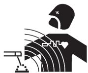
Arc welding can be dangerous and can cause serious and even fatal injuries.
Welding exposes the user to dangerous heat, arc rays, electromagnetic fields, noise, gas fumes, and electrical shocks. People wearing pacemakers are advised to consult with their doctor before using this device.
To protect oneself as well as the other, ensure the following safety precautions are taken:

In order to protect you from burns and radiations, wear clothing without cuffs. These clothes must be insulated, dry, fireproof and in good condition, and cover the whole body.

Wear protective gloves which guarantee electrical and thermal insulation.

Use sufficient welding protective gear for the whole body: hood, gloves, jacket, trousers... (varies depending on the application/operation). Protect the eyes during cleaning operations. Do not operate whilst wearing contact lenses. It may be necessary to install fireproof welding curtains to protect the area against arc rays, weld spatters and sparks.
Inform the people around the working area to never look at the arc nor the molten metal, and to wear protective clothes.

Ensure ear protection is worn by the operator if the work exceeds the authorised noise limit (the same applies to any person in the welding area).
Stay away from moving parts (e.g. engine, fan...) with hands, hair, clothes etc...
Never remove the safety covers from the cooling unit when the machine is plugged in - The manufacturer is not responsible for any accident or injury that happens as a result of not following these safety precautions.
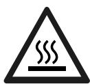
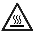
The pieces that have just been welded are hot and may cause burns when manipulated. During maintenance work on the torch or the electrode holder, you should make sure it's cold enough and wait at least 10 minutes before any intervention. The cooling unit must be on when using a water cooled torch in order to ensure that the liquid does not cause any burns.
ALWAYS ensure the working area is left as safe and secure as possible to prevent damage or accidents.
WELDING FUMES AND GAS

The fumes, gases and dust produced during welding are hazardous. It is mandatory to ensure adequate ventilation and/or extraction to keep fumes and gases away from the work area. An air fed helmet is recommended in cases of insufficient air supply in the workplace.
Check that the air intake is in compliance with safety standards
Care must be taken when welding in small areas, and the operator will need supervision from a safe distance. Welding certain pieces of metal containing lead, cadmium, zinc, mercury or beryllium can be extremely toxic. The user will also need to degrease the workpiece before welding.
Gas cylinders must be stored in an open or ventilated area. The cylinders must be in a vertical position secured to a support or trolley. Do not weld in areas where grease or paint are stored.
FIRE AND EXPLOSIONS RISKS

Protect the entire welding area. Compressed gas containers and other inflammable material must be moved to a minimum safe distance of 11 meters.
A fire extinguisher must be readily available.
Be careful of spatter and sparks, even through cracks. It can be the source of a fire or an explosion.
Keep people, flammable objects and containers under pressure at a safe distance.
Welding of sealed containers or closed pipes should not be undertaken, and if opened, the operator must remove any inflammable or explosive materials (oil, petrol, gas...).
Grinding operations should not be directed towards the device itself, the power supply or any flammable materials.
GAS BOTTLE

Gas leaking from the cylinder can lead to suffocation if present in high concentrations around the work area.
Transport must be done safely: Cylinders closed and product off. Always keep cylinders in an upright position securely chained to a fixed support or trolley.
Close the bottle after any welding operation. Be wary of temperature changes or exposure to sunlight.
Cylinders should be located away from areas where they may be struck or subjected to physical damage.
Always keep gas bottles at a safe distance from arc welding or cutting operations, and any source of heat, sparks or flames.
Be careful when opening the valve on the gas bottle, it is necessary to remove the tip of the valve and make sure the gas meets your welding requirements.
ELECTRIC SAFETY

The machine must be connected to an earthed electrical supply. Use the recommended fuse size. An electrical discharge can directly or indirectly cause serious or deadly accidents.
Do not touch any live part of the machine (inside or outside) when it is plugged in (Torches, earth cable, cables, electrodes) because they are connected to the welding circuit.
Before opening the device, it is imperative to disconnect it from the mains and wait 2 minutes, so that all the capacitors are discharged. Do not touch the torch or electrode holder and earth clamp at the same time.
Damaged cables and torches must be changed by a qualified and skilled professional. Make sure that the cable cross section is adequate with the usage (extensions and welding cables). Always wear dry clothes in good condition, in order to be insulated from the electrical circuit. Wear insulating shoes, regardless of the environment in which you work in.
EMC CLASSIFICATION

These Class A devices are not intended to be used on a residential site where the electric current is supplied by the public network, with a low voltage power supply. There may be potential difficulties in ensuring electromagnetic compatibility on these sites, because of the interferences, as well as radio frequencies.
This equipment does not comply with IEC 61000-3-12 and is intended to be connected to private low-voltage systems interfacing with the public supply only at the medium- or high-voltage level. On a public low-voltage power grid, it is the responsibility of the installer or user of the device to ensure, by checking with the operator of the distribution network, which device can be connected.

This equipment complies with the IEC 61000-3-11 standard.
ELECTROMAGNETIC INTERFERENCES

The electric currents flowing through a conductor cause electrical and magnetic fields (EMF). The welding current generates an EMF field around the welding circuit and the welding equipment.
The EMF fields may disrupt some medical implants, such as pacemakers. Protection measures should be taken for people wearing medical implants. For example, access restrictions for passers-by or an individual risk evaluation for the welders.
All welders should take the following precautions in order to minimise exposure to the electromagnetic fields (EMF) generated by the welding circuit:
- position the welding cables together – if possible, attach them;
- keep your head and torso as far as possible from the welding circuit;
- never enroll the cables around your body;
- never position your body between the welding cables. Hold both welding cables on the same side of your body;
- connect the earth clamp as close as possible to the area being welded;
- do not work too close to, do not lean and do not sit on the welding machine
- do not weld when you're carrying the welding machine or its wire feeder.

People wearing pacemakers are advised to consult their doctor before using this device.
Exposure to electromagnetic fields while welding may have other health effects which are not yet known.
RECOMMANDATIONS TO ASSES THE AREA AND WELDING INSTALLATION
Overview
The user is responsible for installing and using the arc welding equipment in accordance with the manufacturer's instructions. If electromagnetic disturbances are detected, it is the responsibility of the user of the arc welding equipment to resolve the situation with the manufacturer's technical assistance. In some cases, this remedial action may be as simple as earthing the welding circuit. In other cases, it may be necessary to construct an electromagnetic shield around the welding power source and around the entire piece by fitting input filters. In all cases, electromagnetic interferences must be reduced until they are no longer bothersome.
Welding area assessment
Before installing the machine, the user must evaluate the possible electromagnetic problems that may arise in the area where the installation is planned.
In particular, it should consider the following:
a) the presence of other power cables (power supply cables, telephone cables, command cable, etc...) above, below and on the sides of the arc welding machine.
b) television transmitters and receivers;
c) computers and other hardware;
d) critical safety equipment such as industrial machine protections;
e) the health and safety of the people in the area such as people with pacemakers or hearing aids;
f) calibration and measuring equipment
g) the isolation of the equipment from other machinery.
The user will have to make sure that the devices and equipments that are in the same room are compatible with each other. This may require extra precautions;
h) make sure of the exact hour when the welding and/or other operations will take place.
The surface of the area to be considered around the device depends on the the building's structure and other activities that take place there. The area taken in consideration can be larger than the limits determined by the companies.
Welding area assessment
Besides the welding area, the assessment of the arc welding systems installation itself can be used to identify and resolve cases of disturbances. The assessment of emissions must include in situ measurements as specified in Article 10 of CISPR 11. In situ measurements can also be used to confirm the effectiveness of mitigation measures.
RECOMMENDATION ON METHODS OF ELECTROMAGNETIC EMISSIONS REDUCTION
a. National power grid : The arc welding machine must be connected to the national power grid in accordance with the manufacturer's recommendation. If interferences occur, it may be necessary to take additional preventive measures such as the filtering of the power supply network. Consideration should be given to shielding the power supply cable in a metal conduit. It is necessary to ensure the shielding's electrical continuity along the cable's entire length. The shielding should be connected to the welding current's source to ensure good electrical contact between the conduct and the casing of the welding current source.
b. Maintenance of the arc welding equipment : The arc welding machine should be be submitted to a routine maintenance check according to the manufacturer's recommendations. All accesses, service doors and covers should be closed and properly locked when the arc welding equipment is on. The arc welding equipment must not be modified in any way, except for the changes and settings outlined in the manufacturer's instructions. The spark gap of the arc start and arc stabilization devices must be adjusted and maintained according to the manufacturer's recommendations.
c. Welding cables : Cables must be as short as possible, close to each other and close to the ground, if not on the ground.
d. Electrical bonding : consideration should be given to bonding all metal objects in the surrounding area. However, metal objects connected to the workpiece increase the risk of electric shock if the operator touches both these metal elements and the electrode. It is necessary to insulate the operator from such metal objects.
e. Earthing of the welded part : When the part is not earthed - due to electrical safety reasons or because of its size and its location (which is the case with ship hulls or metallic building structures), the earthing of the part can, in some cases but not systematically, reduce emissions It is preferable to avoid the earthing of parts that could increase the risk of injury to the users or damage other electrical equipment. If necessary, it is appropriate that the earthing of the part is done directly, but in some countries that do not allow such a direct connection, it is appropriate that the connection is made with a capacitor selected according to national regulations.
f. Protection and plating : The selective protection and plating of other cables and devices in the area can reduce perturbation issues. The protection of the entire welding area can be considered for specific situations.
TRANSPORT AND TRANSIT OF THE WELDING MACHINE

This welding power source comes equipped with a top strap so that it can be carried by hand. Be careful not to underestimate its weight. The strap is not intended to be used to suspend or hang the device.
Do not use the cables or torch to move the welding power source. It should be moved in an upright position. Do not carry or transport the power source overhead of people or objects. It is advisable to remove the wire-feed spool before lifting or transporting the welding power source.
EQUIPMENT INSTALLATION
- Put the machine on the floor (maximum incline of 10^ ).
- Ensure the work area has sufficient ventilation for welding, and that there is easy access to the control panel.
- The machine must not be used in an area with conductive metal dusts.
- The machine must be placed in a sheltered area away from rain or direct sunlight.
- The machine protection level is IP21, which means :
- Protection against access to dangerous parts from solid bodies of a ≥ 12.5mm diameter and,
- Protection against vertically falling drops.
The power cables, extensions and welding cables must be fully uncoiled to prevent overheating.

The manufacturer does not incur any responsibility regarding damages to both objects and persons that result from an incorrect and/or dangerous use of the machine.

Stray welding currents/voltages may destroy earth conductors, damage electrical equipment or cause components to warm up which may cause a fire.
- All welding connections must be firmly secured, check regularly!
- Check that the metal piece fixation is strong and without any electrical problems !
- Attach or hang all the electrically conductive elements, such as the trolley in order to insulate them.
- Do not place any electrical equipment such as drills on top of the welding machine without insulating them !
- Always place welding torches or electrodes holders on an insulated surface when they're not in use !
MAINTENANCE / RECOMMENDATIONS

- Maintenance should only be carried out by a qualified person. Annual maintenance is recommended.
- Ensure the machine is unplugged from the mains, and wait for two minutes before carrying out maintenance work. DANGER High Voltage and Currents inside the machine.
- Remove the casing 2 or 3 times a year to remove any excess dust. Take this opportunity to have the electrical connections checked by a qualified person, with an insulated tool.
- Regularly check the condition of the power supply cable. If the power cable is damaged, it must be replaced by the manufacturer, its after sales service or an equally qualified person.
- Ensure the ventilation holes of the device are not blocked to allow adequate air circulation.
- Do not use this equipment to thaw pipes, to charge batteries, or to start any engine.
INSTALLATION - USING THE PRODUCT
Only experienced personnel, authorised by the manufacturer, may carry out the machine's set-up. During set-up, ensure that the power source is unplugged from the mains. It is recommended to use the welding cables supplied with the unit in order to obtain the optimum product settings.
DESCRIPTION
Thank you for choosing this machine. To get the best use from your machine, please read the following carefully : The EASYMIG range are semi-automatic MIG/MAG, MMA and flux cored wire welding stations. They are manual settings machine, with the help of the table printed on the product. They are recommended for welding steel, stainless steel and aluminium.
POWER SUPPLY
This machine is fitted with a 16A socket type CEE7/7 which must be connected to a single-phase 230V (50 - 60 Hz) power supply fitted with three wires and one earthed neutral. The absorbed current (I1eff) is indicated on the device at maximum usage. Check that the power supply and its protection (fuse and/or circuit breaker) are compatible with the current needed for use. In some countries, it might be necessary to change the plug to allow maximum performance. The device must be installed so that the mains socket is accessible.
MACHINE DESCRIPTION (FIG I)
1- Adjustment of welding settings (wire speed, welding voltage and inductance).
2- Switch MIG/ MMA
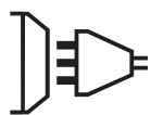
3- European standard torch connection.
4- Connectors
5- Polarity reversal cable
6- Power Cable (2 m)
7- Power switch
Reel adaptor 100/200mm (EASYMIG 160)
8 Reel adaptor 200/300mm (EASYMIG 180-4XL)
9- Digital displays
USING EXTENSION LEADS
All extension leads must be of a size and cross-section appropriate for the equipment's voltage.
Use an extension lead that complies with national safety regulations.
| Input voltage | Extension-lead length (<45 m) |
| 230 V - 1~ | 1.5 mm² |
SEMI-AUTOMATIC WELDING FOR STEEL / STAINLESS STEEL (MAG MODE)
Set the voltage output and the wire speed according to the thickness of the weld piece, following the instructions/recommendations printed on the side of the machine.
The EASYMIG can weld Steel wire 0.6/0.8mm, and Stainless Steel of 0.8mm.
The machine is fitted with 0.8mm Steel or Stainless Steel rollers. The contact tube, the groove of the roller and the sleeve of the torch are all compatible with 0.8mm wire. Should you wish to weld 0,6 wire, use a torch of maximum 3m long. The contact tip must be changed (fig IV-D) as well as the wire feeder's roller that must be replaced by an optional reference (042339) with a 0.6 diameter groove. In this case, the position in such a way to observe 0.6. For use with Steel, the gas requirement is argon + CO2. (Ar+CO2). The proportion of CO2 required will vary depending on the use. For Stainless Steel, use the combination of 2% CO2 For specific gas requirements, please contact your gas distributor. The gas flow in steel is between 8 and 12 Litres/minute depending on the environment. Maximum gas pressure : 0.5 MPa (5 bars).
SEMI-AUTOMATIC WELDING FOR ALUMINIUM (MIG MODE)
Set the voltage output and the wire speed according to the thickness of the weld piece, following the instructions/recommendations printed on the side of the machine.
The EASYMIG can be equipped to weld with aluminium wire 0,8 or 1,0 (fig II-B).
For use with aluminium, the gas requirement is pure argon (Ar). For the specific gas requirements please contact your distributor. The gas flow in Aluminium is between 20 and 30 Litres/minute depending on the environment, and the experience of the welder. Maximum gas pressure : 0.5 MPa (5 bars).
Below are the differences between welding with Steel and Aluminium :
- Specific rollers are needed for welding with Aluminium.
- Adjust the pressure of the drive rolls to prevent the wire being crushed.
- Only use a capillary tube for welding with Steel or Stainless Steel.
- Use a special Aluminium Torch with a teflon sheath to reduce friction.
DO NOT cut the sheath close to the joint, it is used to guide the wire from the the rollers. - Contact Tube : Use a special aluminium contact tube specific to the diameter of wire being used.
GASLESS WIRE WELDING
Set the voltage output and the wire speed according to the thickness of the weld piece, following the instructions/recommendations printed on the side of the machine.
The EASYMIG can weld gasless wire up to 0.9mm , if the polarity is reversed respecting a maximum pressure of 5Nm. For parameters of use, please refer to the instructions indicated on page 75. Welding gasless wire with a standard nozzle can lead to overheating and deterioration of the torch. It is recommended to use a "No Gas" nozzle (ref. 041868), or remove the genuine nozzle (Fig. III).
ELECTRODE WELDING
- The reverse polarity cable must be disconnected in MMA (stick welding) mode in order to connect the electrode holder and earth clamp. Connect the electrode holder and earth clamp as indicated on the electrode packaging.
- Respect the basic rules of welding.
- This device has 1 feature specific to Inverter machines :
- Anti-Sticking: Enables easy removal of the electrode from the metal. The anti-sticking feature, after its start, requires approximately a 3 seconds delay before resuming normal welding operations.
SETTINGS PANEL (FIG V)
| 1 | ·Green light «ON»: when the machine is switched on the light turns on. ·In case of power failure, the green light goes off but the device remains powered while the power cable is unplugged. | ON |
| 2 | Orange light: ·Over-temperature: in such a case you shall wait a few minutes, the light will turn off and the machine will start again. ·Over-current on primary circuit: in such a case you shall switch off the machine (with the main switch) and switch on. | |
| 3 | ·Left button: - MIG / MAG Welding : Adjust the wire feeder speed up to maximum speed. -MMA welding : Adjust the welding current. | 6 7 5 9 10 4 8 11 12 13 14 15 16 17 18 19 20 21 22 23 24 25 26 27 28 29 30 31 32 33 34 35 36 37 38 39 40 41 42 43 44 45 46 47 48 49 50 51 52 53 54 55 56 57 58 59 60 61 62 63 64 65 66 67 68 69 70 71 72 73 74 75 76 77 78 79 80 81 82 83 84 85 86 87 88 89 90 91 92 93 94 95 96 97 98 99 100 101 102 103 104 105 106 107 108 109 110 111 112 113 114 115 116 117 118 119 120 121 122 123 124 125 126 127 128 129 130 131 132 133 134 135 136 137 138 139 140 141 142 143 144 145 146 147 148 149 150 151 152 153 154 155 156 157 158 159 160 161 162 163 164 165 166 167 168 169 170 171 172 173 174 175 176 177 178 179 180 181 182 183 184 185 186 187 188 189 190 191 192 193 194 195 196 197 198 199 200 201 202 203 204 205 206 207 208 209 210 211 212 213 214 215 216 217 218 219 220 221 222 223 224 225 226 227 228 229 230 231 232 233 234 235 236 237 238 239 240 241 242 243 244 245 246 247 248 249 250 251 252 253 254 255 256 257 258 259 260 261 262 263 264 265 266 267 268 269 270 271 272 273 274 275 276 277 278 279 280 281 282 283 284 285 286 287 288 289 290 291 292 293 294 295 296 297 298 299 300 301 302 303 304 305 306 307 308 309 310 311 312 313 314 315 316 317 318 319 320 321 322 323 324 325 326 327 328 329 330 331 332 333 334 335 336 337 338 339 340 341 342 343 344 345 346 347 348 349 350 351 352 353 354 355 356 357 358 359 360 361 362 363 364 365 366 367 368 369 370 371 372 373 374 375 376 377 378 379 380 381 382 383 384 385 386 387 388 389 390 391 392 393 394 395 396 397 398 399 400 401 402 403 404 405 406 407 408 409 410 411 412 413 414 415 416 417 418 419 420 421 422 423 424 425 426 427 428 429 430 431 432 433 434 435 436 437 438 439 440 441 442 443 444 445 446 447 448 449 450 451 452 453 454 455 456 457 458 459 460 461 462 463 464 465 466 467 468 469 470 471 472 473 474 475 476 477 478 479 480 481 482 483 484 485 486 487 488 489 490 491 492 493 494 495 496 497 498 499 500 501 502 503 504 505 506 507 508 509 510 511 512 513 514 515 516 517 518 519 520 521 522 523 524 525 526 527 528 529 530 531 532 533 534 535 536 537 538 539 540 541 542 543 544 545 546 547 548 549 550 551 552 553 554 555 556 557 558 559 560 561 562 563 564 565 566 567 568 569 570 571 572 573 574 575 576 577 578 579 580 581 582 583 584 585 586 587 588 589 590 591 592 593 594 595 596 597 598 599 600 601 602 603 604 605 606 607 608 609 610 611 612 613 614 615 616 617 618 619 620 621 622 623 624 625 626 627 628 629 630 631 632 633 634 635 636 637 638 639 640 641 642 643 644 645 646 647 648 649 650 651 652 653 654 655 656 657 658 659 660 661 662 663 664 665 666 667 668 669 670 671 672 673 674 675 676 677 678 679 680 681 682 683 684 685 686 687 688 689 690 691 692 693 694 695 696 697 698 699 700 701 702 703 704 705 706 707 708 709 710 711 712 713 714 715 716 717 718 719 720 721 722 723 724 725 726 727 728 729 730 731 732 733 734 735 736 737 738 739 740 741 742 743 744 745 746 747 748 749 750 751 752 753 754 755 756 757 758 759 760 761 762 763 764 765 766 767 768 769 770 771 772 773 774 775 776 777 778 779 780 781 782 783 784 785 786 787 788 789 790 791 792 793 794 795 796 797 798 799 800 801 802 803 804 805 806 807 808 809 810 811 812 813 814 815 816 817 818 819 820 821 822 823 824 825 826 827 828 829 830 831 832 833 834 835 836 837 838 839 840 841 842 843 844 845 846 847 848 849 850 851 852 853 854 855 856 857 858 859 860 861 862 863 864 865 866 867 868 869 870 871 872 873 874 875 876 877 878 879 880 881 882 883 884 885 886 887 888 889 890 891 892 893 894 895 896 897 898 899 900 901 902 903 904 905 906 907 908 909 910 911 912 913 914 915 916 917 918 919 920 921 922 923 924 925 926 927 928 929 930 931 932 933 934 935 936 937 938 939 940 941 942 943 944 945 946 947 948 949 950 951 952 953 954 955 956 957 958 959 960 961 962 963 964 965 966 967 968 969 970 971 972 973 974 975 976 977 978 979 980 981 982 983 984 985 986 987 988 989 990 |
| Advices The wire speed adjustment is often determined « with the assistance of sound «: the arc must be stable and have a low crackling. If the speed is too low, the arc is not continuous. If the speed is too high, the arc crackles and the wire pushes back the torch. The inductance adjustment is done according to the welder's preferences: The lower the inductance, the more the arc will be hard and guiding. The higher the inductance and the softer the arc with little splatter. | ||
PROCESS OF REELS AND TORCHES ASSEMBLY (FIG IV)
- Remove the contact tube and its support (fig D), and the nozzle (fig E) from the torch.
Fig A :
- Position the wire reel on the reel support :
- Adjust the reel brake (1) to avoid reel movement tangling the wire when welding stops. Be careful not to tighten too much.
For a 200mm wire reel tighten the reel to the maximum. The adaptor (4) is only to be used for a 200mm reel.
Fig B:
The drive rollers included have 2 grooves (0,8 and 0,9). For 0.8mm steel wire, use the V shaped groove. For flux cored wire, remove and reverse the roller to use the 0.9mm groove.
For 0.8mm aluminium wire, remove and replace the roll with a model specifically designed for aluminium with a U shaped groove (not included).
Fig C:
To select the adjustment of the drive rollers.
- Loosen the drive roller knob (3) as far as possible and insert the wire, tighten the knob again slightly.
- Start the motor by pressing the trigger of the torch.
- Tighten the knob whilst pressing the trigger until the wire starts to move.
Nb : When welding with Aluminium, use the minimum possible pressure to avoid crushing the wire
- Leave about 5cm of wire out of the torch, then put the contact tube (fig. D), and the nozzle (fig. E) adapted to the wire to be used at the extremity.
GAS COUPLING
-
Connect a pressure regulator to the gas bottle. Connect the welding machine (fig. F) using the pipes supplied, and place the two clamps to avoid leakages.
-
Set the gas flow by adjusting the dial located on the pressure regulator.
NB : to help facilitate the adjustment of the gas flow, operate the drive rollers by pressing the trigger of the torch (ensure that the drive roller is completely loose so the wire is not fed through).
This procedure does not apply to «Gasless» welding mode.
RECOMMENDED COMBINATIONS
| (mm) | Current (A) | Ø Wire (mm) | Ø Nozzle (mm) | Flow rate L/min | |
| MIG | 0.8-2 | 20-100 | 0.8 | 12 | 10-12 |
| 2-4 | 100-200 | 1.0 | 12-15 | 12-15 | |
| MAG | 0.6-1.5 | 15-80 | 0.6 | 12 | 8-10 |
| 1.5-3 | 80-150 | 0.8 | 12-15 | 10-12 | |
| 3-8 | 150-300 | 1.0/1.2 | 15-16 | 12-15 |
RISK OF INJURY DUE TO MOVING PARTS

The wire feeders contain moving parts that may catch hand, hair, clothes or tools which can lead to injuries! Take extra care.
- Do not lay a hand to swivel or moving components or parts to the drive!
-
Ensure that the housing covers or protective covers remain closed during operation!
-
Do not wear gloves when threading the filler wire and changing the filler wire spool.
ADVICE & THERMAL PROTECTION
This device is equipped with a ventilator regulated by the inside temperature. When the machine's thermal protection is activated, it will not deliver any current. Orange light (Fig-V-2) will turn on until the temperature of the machine has returned to normal.
- Do not block/cover the ventilation holes, ensure free flow of air.
- Whilst in thermal protection mode leave the machine plugged into the mains after welding to allow it to cool.
General observations :
- Always respect the basic rules of welding.
- Always work in an adequately ventilated area.
- Do not work on a damp surface.
TROUBLESHOOTING
| SYMPTOMS | POSSIBLE CAUSES | REMEDIES |
| The welding wire speed is not constant. | Debris is blocking up the opening. | Clean out the contact batch or change it and replace the anti-adherence product. Ref.041806. |
| The wire skids in the rollers. | • Control the roller pressure or replace it. • Wire diameter non-compatible with roller • Covering wire guide in the torch non-compatible. | |
| The wire-feeder motor doesn’t operate. | Reel or roller brake too tight. | Release the brake and rollers. |
| Electrical supply problem. | Check that the power switch is in the "On" position. | |
| Bad wire feeding. | Covering wire guide dirty or damaged. | Clean or replace |
| The drive roller is too loose | Tighten the drive roller knob | |
| Reel brake too tight | Release the brake | |
| No welding current | Bad connection to the main supply. | Check the mains connection and look if the plug is fed by 230 V (1PH) power socket. |
| Bad earth connection. | Check the earth cable (connection and clamp condition). | |
| Torch trigger inoperative. | Check the torch trigger / replace torch | |
| The wire jams (after the rollers) | Guide wire sheath crushed. | Check the sheath and torch body. |
| Wire jammed in the torch | Clean or replace. | |
| No capillary tube. | Check the presence of capillary tube. | |
| Wire speed too fast | Reduce the wire speed | |
| The welding bead is porous | The gas flow rate is not sufficient. | Adjust flow range 15 to 20 L / min. |
| Clean the working metal. | ||
| Gas bottle empty. | Replace it. | |
| Gas quality unsatisfactory. | Replace it. | |
| Air flow or wind influence. | Prevent drafts, protect welding area. | |
| Gas nozzle dirty. | Clean or replace the gas nozzle. | |
| Poor quality wire. | Use suitable WIRE for MIG-MAG welding. | |
| Surface to weld in bad condition. (rust, etc...) | Clean the metal before welding. | |
| Very important flashing particules. | Arc voltage too low or too high. | See welding settings. |
| Bad earth connection. | Adjust the earth cable for a better connection. | |
| Insufficient gas flow. | Adjust the gas flow. | |
| No gas flow at the end of the torch. | Bad gas connection. | Check the gas connection at the welding machine. Check the gas regulator and the solenoid valves. |
WARRANTY
The warranty covers faulty workmanship for 2 years from the date of purchase (parts and labour).
The warranty does not cover:
- Transit damage.
- Normal wear of parts (eg.: cables, clamps, etc.).
- Damages due to misuse (power supply error, dropping of equipment, disassembling).
- Environment related failures (pollution, rust, dust).
In case of failure, return the unit to your distributor together with:
- The proof of purchase (receipt etc ...)
- A description of the fault reported.

OKPYXKAHOUJIAR CPEDA
3To 60bOBAHn D0JIKHO 6bITb NcIIOB3OBAHO NCKIIIOHTeBHO DJIa CBAPoHybIX pa60T, OrpaHnUBaRc bYka3aHnM 3aBOIDcOy Ta6IuHKn H/INn INCTpyKcun. Heo6XoIMMo CO6JIIODaT bInepeKTNBbl NO mepam 6e3OnacHocTn. B clyuae HeHaJnxKaIero nnn OnaCHOrO NcIIOB3OBAHn IPOUN3BOIDTeB He HeCET OTBETCTBeHHOCtN.
Annapat dOJxhen 6bIb yCTaHOBlen B nOMEeHn 6e3 nbIn, KcNtObl, Bo3rpaembx rA3OB, nn Dpyrnx Koppo3n HbIX BeuectB. TaKne JyCIOBn IOnXhbl 6bIb coJIIOHeHbI dJe erO xpaHEnHry. Y6eINTEcb B npncytCTBn BEHTnlaunn npn NcNOJb30BaHm annapapata.
Tempepatypnbie ppejbl:
IcnoJIb3OBAHnE: oT -10 do +40°C (oT +14 do +104°F).
XpaHHeH: oT -20 do +55°C (oT -4 do 131°F).
BlaJxHocTb Bo3dyxa:
50% nii nHXke npn 40^ (104^)
90% nii nixe npn 20^ (68^)
BbICota NaI yPObHem MOpA:
1000M BbICToBHaD yPoBHeM MOp8 (3280 cyTob).
INHINBIVDyAJIbHA 3AUNTA IN 3AUNTA OKPYXKAIOUX
DyroBa CbapKa MoKet 6bIb OaCHO N Bb3BaTb TAgKeIbIe I daKe CMePeTbHbIe paHeHn.
Cbapouhble pa60tbl noDBepraHOT nolb3OBateIg Bo3dECTBnIO onaCHORIO hCTOuHnka TeNla, CBETOBORIO n3JlyueHnry dYrN, 3JIeKtpOMarHnTHbIX nOJIe (OCo6oe BHNMaHHe IIncAm, IMeIoUIm 3JIeKTPOKApDIOCTMMyJrTOp), CNJIbHOMy 7UMy, BblJeHnM ra3a, a TAKKe MOrYT cTaTB npuHHo NopaxeHnry 3JIeKTPnueCKm TOKOM.
YTo 6bl npabnIbHO 3aunITnb ce6n 3aunITnb OkpykaIoUx, co6nOdaJte cneDyIoune npabuna 6e3oNaChocnt:

YTo6bI 3aunTb Ce6r OTOXOROB N O6nyehn npn pa6ote c annapatom, HadeBaTe cyxuipo6ouyio 3aunTHyIO Odekdy (B XopoWeem COCTOAHIN) n3 orHeynopHoi TkaHn, 6e3 OTBOPOTOB, KOtopa IOKpbIBaET IONHOCTbIO BCE TeNo.

Pa6oTaIe B 3aUHTbIX pyKabuIax, o6ecneUHbIoUne 3JeKtro- I TepMOH3OJIaIIO.

IcnoJIb3yIte cpeCTBa 3aIITbI dIe CBapKn I/IIIN IJIeM dIe CBapKn COOTBeTCTBYIOEro yPoBHe 3aIITbI (B 3aBVCIMOCtNtncOJIb3OBAHnI).3aIITeTgla3aIprnOepaunxOuNCtKn.HoSeHneKoHTaKTHbIXJINH3BOCnPeeTaetc. B HeKOTOpbIX ClyuaX He06XODIMO OKpyXnTb 3OHy ORHeYIpOBHIMU 7TOPaMI,
yTO6bI 3aunITb 30Hy CBAPKn OT lyuei, 6pbI3r n HakaJIeHHoro 7Jlaka. IpeDynpTe OkpykaIOxH He cMOptb Ha nyu o6pa6aTbIBaEMbIe deTaII n HaJeBaTb 3aunTHyo pa6Ouyo odexdy.

Hocnte HauhNKn npotnB yMa, cInn CBapOHybI npoceC DoCTnraet 3ByKOBOrO ypOBHry BblSe D03BOJIeHHOrO (3TO XE OTHOCNTcK KO BCem LlcaM, HaxoJyUIMcR B 3OHe CBapKn).
Держпente pykn, BOLOCbl, Odжду NOdaJIbIe OT NOdBnKHbIX qaCTe (DbngaTeIb, BeHTNJIaTOp...). HNKoIgIa He ChIMaIte 3aUHTbI KOpNc C CnCTeMbl OxlaJckDeHna, KOrDa IcTOUHNK IOd HapprKeHneM. PpOu3BODITeIb He Hecet OTBETCTBeHHOCTN B Clyuae HeCuaCTHOrO Clyuay.
ToIbKO uTo CBapeHHbIe DeTaNr ropAun N MOryT Bbl3BaTb OXoRn npN KOHTaKTe C HIMN. Bo BpeMraTexO6cnykuaHnra RopeJIkn nn 3JeKtpoJodepKaTeIeY6eIntEcB, yTO OHN DoCTaTOUHO OxJaDInLcB INoOxJdnte KaK MnHmym 10 MNHy T nepeh Naalom pa6Ot. PnIN cNoIb3OBAHn n OpeJIkn c XnIDKOCTbIM OXnaJdeHnem CNCTema OXnaJdeHnra DOnkHa 6bItb BKIOueHa, yTO6bI He o6KeYbcr XnIDKOCTbIO.
Oueh baxho 0e3oanacntb pa6oyu 3ohy nepei tem, kak ee noknhyt, yTo6bl 3aunTnTb IIOde N mUyecCTBO.
CBAPOHbIe IdbIM nTg3
BbIbTe BnHMaTeJIbHbI: CBapKa B He6oJIbXnx NOMEuEHNx Tpe6yeT Ha6JIHOeHnHa 6e3OaHOM paCtOHaHm. KpOme toro, CBAPKa HekOTopbIX MeTALIOB, COePkaUx CBnHeU, KaDMn, UINK, pTyTB nII IN dAxe 6epNJIn, MoKeT 6bITb Upe3BbUaHNo BpeHNO. CneDyET OChNTb OT Jknpa DeTAlN nepe CBAPKOi.
ГаэовыббгдгьхьххраньсьВOTКрьтбИxINxopoшОпpoBeTpNBaEmbIXnomeшенyx.ОндлжьбьВВерТикальHOM ПОLOЖЕНИЗAKРENJIЕнБИНСТОКЕИЛТЕХKE.
Hn B Koem Cnyuae He Bapntb 6bn3n Kupa nn Kpaackn.
PNUCKIPOXKAPA INB3PbIBA

POnHocTbIO 3aunntte 30Hy CBapKn. Bo3rOpaemble MaTePnaIbI doJXhbl 6bITb YdaJIeHbI KaK MHNmym Ha 11 MeTpOB. PpOTnBOIpoxkapHoe 6OpuyoBaHne DoJXHO HaxoDITbcra B6JInn IpOBeJeHnra CBapOchbIX pa6Ot.
OcToPoxKHO C 6pbI3ramn ropJrero MaTePnana IIN NCKp, daJe chepe3 uen. OHN MOrT NOBLeuB 3a co6oN noXap IIN B3pbIB. YdaJInte IIOeH, Bo3ropaemblte ppeMeTb I BCE emKOCTn IOd daBHeHEm Ha 6e3OnaChoe paCCToHHe.
Hn B KOem cnyaee He Bapnte B KOHTeHepax IIN 3akpbIbIX Tpy6ax. B cnyae, ecIn OHI OTKpbITbI, To neped CBAPKO INx HUJHO OCBO6OuNTb OT BCEX B3pbIbHaTbIX IIN BO3rOpaEmbIX BeIeCTB (MaCNo, TOJIINBO, OCTaTOHbI grea3bl ...).
Bo Bpem Oepaunn IInIfoBaHnne HnnpabTte INCTpyMeHT B CTOPOHy NCTOCHNka CBapOHoro Toka nn Bo3ropaembIX MaTePnaJIOB.
T430BbIE BAJIIOHbl

a30M , BbIXOaIIM n3 ra3OBbIX 6aJIIOHOB, MOxHOb 3aDOXHyTbcR B Cnyuae erO KOHcHTpaUIN B IOMeUeHN CBapKIN (xopoio npoBeTpBaaiTe).
TpaHcnpOpBbKa DOLJXHa 6bITb 6e3OanChOH : npn 3aKpbIbIX ra3OBbIX 6aJIIOHOB n BvIKNoUeHHOM nCTOCHNe. BaJIIOHbI DOJIxHbI 6bITb B VePTNkaJIbHOM NIOLOXKeHNn N 3aKpeJIleHbI Ha NODCTaBKe, UTO6bI OrpaHUnITb PnCK naDeHn.
3aKpbIbaiTe 6aJIIOH B IpepeBbIe MExdy DByM y CNoJIb3OBAHnAMy. ByIbTe BHIMaTeJIbHbI K N3MeHeHIO TempepaTpybI n Ipe6bIBaHIO Ha coJIHcE.
Baanon He doJxhen cOnpnaCaTbCn PJIaMeHem, 3neKtpnuecko Dyro, rOpelko, 3axmOM Maccbl nIc CIO6bIM dpyrM INCTOHNKOM Tepna nIi CBeueHn.
JepKnte ero noaJIbwe ot 3JeKtpnuecknx n CBapOuHbIX cIeNei n, CJIeIOBaTeNbHO, HIKoTgA He BapNTe 6aJIIOH NOI daBLeHneM. BydbTe BHNMaTeMbHi: npN OTkpbltnn BeHTnla 6aJIIOHa y6epNTe rIoBOy OT BeHTnla n y6eINTEcB, YTO IcNoJIb3yEmbI ra3 COOTBETCTByET MeToDy CBapKn.
3JIeKTPnueCKa B3OnACHOCTb

IcnoJIb3yemaj 3eKtpnuecka CeT bdoJxHa o63aTeNbHO 6bTb 3a3EmHNo. Co6IIOaJte KaJIb6p npedeoxpaHntela Yka3aHHb Ha aannapate. 3eKtpnueckn pa3prd MOKeT BblBaTb npMble IIN KocBHeHbIe paHeHn, n daXe CMeptb.
Hnkorga He doTpaBnBaIteb do cacte NOD HaprJxHeM KAK BHTPN, TAK IN ChapyKIN ICTOHNKA, KOrda OH NOd HaprJxHeM (ropeKN, 3axmbl, Ka6enl, 3neKTPOdb), T.K. OHI NODKJIIOUeHb K CBAPoHOn CEIN.
Ipeen TeM, KaK OTKpbITb NCTOCHNK, eRO HxKHO OTKJIIOUHTb OT CeTn INoDOXdA Tb 2 MInHyTbI DnI TORo, YTO6bl BCE KOHdeHcaTopbI pa3pndJINCb.
HnKOrda He DToParnBaIteCb ODNOBpeMeHNO Do ropeKn IJIN 3eKtpoOdePkaTeJI N Do 3aXIMa MaCbl.
Ecn Kabei, RopEnKn NOBpeXdeHbI, Nonpocnte KBaInNfUnpoBaHHbx IN yNoIHOmOeHHbx CneuaJIncTOB IN 3aMeHNTb. Pa3Mepbl CeueHnka6eJe IOnJhBi COOTBeTCTBOBaTb PnIMeHHeHIO. Bcerda Hocnte cyxuy Odekdy B XopoWem CoCToAHIN dIy I30JIaUN OT CBAPouHNO CEHN. HocTe n3OInpyUsoYIO oSyBb He3aBNCIMO OT ToI cpeBb, rIe Bbl pa6oTaete.
KJIACCHIKAÇNIA 3JEKTPOMAGHHTHOJ COBMECTMIOCTN

3TO 6ObOpUdOBaHnne Klacca A He NODXoDIT IINCNoJIb3OBAHnB XJINbIX KBapTaJax, rIe 3JeKTPnueckn TOK NOdaTcR 6OuEcTeBHeHHo CnCTeMoN PNTaHn Hn3KOrO HAnpJxKeHn. B TaKnx KBapTaJax MOrYT Bo3HnKHyTb TpyDnOCTn OBeCpeHnna 3JeKTPomarHHTHyIO COBMeCTnMOCTb I3-3a KOHdyKTnBbIX INHdyKTNBbIX NOMEx Ha paAnouactote.
3TOT annapat He cootbetCTbyet dapekTbe CEI 61000-3-12 n npedna3haueH nla pa6oTbO t OaCThbx 3Neektpocetei, NOBdeHHbIX K o6eCTBeHHbIM 3NeektpocetTm TolbKO cpeHero N BbICOKO r HapJxehn. CneuaJIcT, yctahOBuBwI aannapaT, INN pONb3OBAteIb, DOJXhbl y6eHTbcr, 6paTNBWncb npn HADObHocTN K opraHn3aun, OTBeauOe3 3a EKcnPlyatauCnTeMbI PNTAHn, B TOM, YTO OH MOKeT K He IPODKluOHtbcR.

3TOT annapat COOTBeTCTByET HopMe CEI 61000-3-11.
MAGHNTbIe NOJIa
3NeKtpnueckn TOK, npoxoJusn chpe3 IIO60 npoBODHk BbI3bIaet IOKaJIIN3OBAHHbIe 3NeKtpomarHHThIe IOnI (EMF). CbapouHbTOK Bbl3bIaET 3NeKtpomarHHTHOe NOJe BOKpyr CBapOCHN OeIN N CBapOCHORO 6OpudBaHn.
3NeKtpomarHnTHbIe noJIy EMF Moryt co3daTb nomexn dJe HeKOToPbIX MeINuHcNx IMnJaHTaTOB, HApnpMep 3NeKtpokapDIOCTmmyJrTopOB. Mepbl 6e3oNaCHOCTn DOJXhbl 6bITb PrnHrTb IJr IIODe, HOCAUx MeINuHcKne IMnJaHTaTbI. HanpMep: orpaHnueHne DoCTyndI pyoxOxnx, nIi OceHKa INDUNDaYalbHoro pNCKa dJIra CBAPsika.
YTo6bI CBeCTN K MInHMMy BO3DeiCTBHe 3JIeKTpOMaHnTHbIX POne iCBapOuHbIX Zpei, CBapUKN DoJxHbI CTeIOBaTb CTeDyHOzIM Yka3aHnM:
- CBAPOCHIe Ka6eIIN DoJXHbI HxOxDtBcR BMeCTe; eCIN BO3MOKHO CoEiHNHTe IX XOMYTOM;
BaIe TUYOBuIe I RIOBa DOnKbI HxOINTbcra KaK MoXHO DaJIbIe OTe CBapOChNo cenN; - He 6MaTbIaIe CBaOpHbIe Ka6eIi BOKpyr BaIero TeJa;
BaIe TeNo He DoJIxHo 6bITb paCnoJoxKeHO mExdy CBapOuHbIMn Ka6eJIaMn. Oba CBapOuHbIX Ka6eJIa DoJIxHbI 6bITb paCnoJoxKeHbI IO ONDy CTOpOHy OT BaUero TeHa; - 3akpeinTe Ka6eJIb 3a3emIeHnHa CbapNbaeMoI DeTaJI N Ka MoxHO 6IuXe C 3OHe CbapKn;
He pa6oTaTe pAOM, He cnDInTe H He o6IoKaunBaIteCb Ha nCTOuHnK CBapOuHOro ToKa; - He BapNTe, KOrDa Bbl IpeHocHTe NCTOChNK CBapOuHoro TOKa IIN YCTpOJCTBO NIOaN NPOBOJOKN.

Iiua, nCnoB3yIOUe 3JeKTPoKAPDIOCTMMyJATOpbl, DOnXHbI npOKOHcyJIbTnPOBaTbcra y Bpaa nepeD pa6Toi C daHHbIM o6OpYDoBaHneM.
Bo3deICTBnE 3JleKtpomarHHTHO nOJI B IpoUeCE CBapKn MoXeT IMeTb N DpyrHe, eIe He I3BeCTHbIe HayKe, PocJeIcTBnI dIy 3DOpOBbI.
PEKOMEHNDAUIN IJIA OULEHKN 3OHBi CBAPKN I CBAPOHON YCTAHOBKN
06une noLOXeHnA
Iolb3OBaTeIb OTBeuAeT 3a yCTaHOKBy I nCIOJIb3OBAHne UCTaHOBKn pyUHOy DnyBOO CBAPKN, CJIeDy Yka3AHnM npON3BOIDTeJI.
Pn O6HApUKeHHN 3JNeKTpOMarHHTbIX N3JIyEHHN IOnb3OBaTeJIb aannapata pyHNO DYROBOCBAPKN DOJXeH pa3peWHTb IpO6JEmy C
NOMoUbIO TexHnueCKo NODepKKn IpnON3BOIDTeJI. B HeKOtOpbIX Clyuayx 3TO KORPeKTHpyUooee DeiCTBNE MOKeT 6bITb DOCTaTOH0
npOCTbIM, HAnPIMep 3a3emLeHne CBAPOUHO uen. B dpyrNX CnyuaX BO3MOXHO NOTpe6byTCs CO3dAHne 3JNeKTpOMarHHTHO 3KpaHa
BOKpyr IVCTOChnKa CBAPOUHOro TOKA IN BCE CBAPINBaEMoI DeTaII NpyTEM MOHTPOBaHHra BXOHBIX PhINbTPOB. B IIO6OM cUYae
3JNeKTpOMarHHTbIe IN3JIyEHHN DOJIXHbI 6bITb YMeHbSeHbI TaK, UTO6bl OH N6JIbSe He CO3DaBAln NOMex.
OuêHka 30HbI CBapKIn
Ipeed yctaHOBko O6OpydoBaHnry DyrOBoi CBApKn Nol3oBaTeN BoJxHeN OueHNb BO3MOXHbE 3eKTPOMarHHTbIe npo6JIembl, KOtOpbIe MOry B03HnKHyTb B OkpyKaIOUeI cpe. CJeDyIOUne MOMeHTb I DoJHXbI 6bITpInHrTbI BO BHMaHHe:
a) Haniuhe Na, noi nn pRdom c o6opudobHnem dIyroBo CBapKn, npnx Ka6eJe nItaHn, ynpabHeN, cnHaJI3aunn TelefoHa;
b) npneMHnki n nepeaTchnk paJno n TeJeBnEHHia;
c) KOMBIOTEPOB IN dpynIX yCTpoiCTB ynpaBJIeHIN;
d) 6opuydoBaHne IaI 6e3oNaChOCTn, Haprimep, 3aunTa npomblJeHHoro 6opuydoBaHna;
e) 3dopobbe HaxoJxnxCno-6n3OCTn IIOde, HapnpMep, nCNoIb3yUoXN KApDIOCTmUyTAOpbl N yCTpOJICTBa O T rIyXOTbl;
f) INCTpymeHT, INCNoIb3yEmblДЯ KaIIN6pOBKn IINn I3MepeHnIA;
g) nomexoyctoynBOCTb dpyrOTo 6OpydoBaHn, HaxoJaIeOc np6bn30ctn.
Iolb3oBaTeB DOnJKeH y6eHtBcR B TOM, YTO BCE aAnpaTbI B NOMEuEHN COBMeCTmbl dpyr C dpyrom. 3TO MOxET nOTpe6oBaTb Co6JIouDeHn DOonJHnTeBhIx Mep 3aunTbI:
h) onpeelenenHoe Bpem dH, KOrda Cbapka IIN npyrgne pa60tb MoxHO 6yET BbInONHHTb.
Pa3mepb paaccmatpmbaem030hcbapkn 3abncrt OT ctpkyktpb3daHnI npytnx pa6oT, KOtOpbE B HEM npOBOJrTc. PaCCMaTPBbEma 30Ha MoKET pOCTnpaTbcra 3a npedeJIb pa3MeueHn yCTaHOBKn.
OuEHa cBapouHoi yCTaHOBKn
IOMIMO OueHKN 30HbI, OueHKa aannapatoB pyHOn dyroBOB CBAPKN MOKeT NOMOy ONpeJeINTB IN peuINTB ClyuaN 3JIeKTPomarHHTbIX NOMex. OueHKa n3JnyeHn DOLJHNa yUHTbIBaTB N3MepeHn B YcIOBnX 3KcPJIyatauN, KAK 3TO yKa3aHO B CtaTbe 10 CISPR 11. N3MepeHn B ycIOBnX 3KcPJIyatauN MOrYT TAKKe I03BOJInTB NODTBePepdINTB 3ΦΦeKTHBHOCTb Mep NO CMYrHeHIO BO3DeIcTBn.
PEKOMEHAZUNI PO METOJNKE CHNXEHNIA 3JIEKTPOMAHHTHOrO N3JIYUHNA
a.ObseCTBeHHaCnCTema nHTAHN: annapat pyHOn dyROBo CBapKn HxKHO NOckIIOHTb K oBSeCTBeHHo Cetn PNTAHN, cIeDypeKOMeHdaunm pOn3BOJntEJI.B Cnyuae BO3HNKHOBEHn NOMEx BO3MOXHO 6yDet Heo6xoJIMO npInrT b DOnOHNTbeHbIe PnpdyPepiTeNbHbIe Mepbl, Takne KaK fNtpaunia OoSceTBHeHNo CnCTembl nHTAHN. Bo3MOXHO 3aUnITb shHypr nHTAHN annapata c NOMOsbIO 3kPaHn3npyUoJe onlETkn, IIN60 NooxKIM pncnOc6JIeHnEM (B cnyae eCIn annapat pyHOn dyROBo
CBAPKN NOCTOHHo HaxoHITcH Ha ONpeDJIeHHom pa6oHem MecTe). Heo6xOJIMO o6ecneHTb 3JeKTPnueCKyU HenpepbHBnocTb 3KpaHn3IpyIOse IOnIETKn IO BceI DInHe. Heo6xOJIMO nOdoCoEINHTb 3KpaHn3IpyIOuSyIO nOIIETKY K NCTOCHNky CBapOHoro TOka DnA O6ecneHnX XopoIeRo 3JeKTPnueCKOrO KOtAKTa Mekdy UHNpOM N KOpNycOM NCTOCHNka CBapOHoro TOka.
b. Texo6cnyxnbHne annapata pyuHoi dyuroBo CBAPK: annapaT pyuHoi DYROBO CBAPKN HUXHO Heo6xoDIMO nepnoOnueckn 06cIyXNBtB corlachO peKOMeHdaunm npOn3BOJnteJI. Heo6xoDIMO, yTO6bl BCE doCTynbl, IIOKn OTKNbIBaHOUIeCg cactn Kopnyca 6bln 3akpytbl n npabNlbHO 3akpenIeHbl, KOrDa annapaT pyuHoi DYROBO CBAPKN rOTOB K pa6ote nn HaxoDITcB pa6oohem coSTOHN. Heo6xoDIMO, yTO6bl annapaT pyuHoi DYROBO CBAPKN He 6bl nepeDeJAN KaKIM 6bl TO HN 6blIO o6pa3OM, 3a NCKIIouHeHem HAcTpoE, Yka3aHHbIX B pYKOBDCTBe npOn3BOJnteJI. B UacTHOCn, CJeDuET OTpeRyIInpOBAbT n ObcLyXNBATb NCKPOBOn IpomexyTok dYrN uCTPOINCTB NOxKnra n CTa6NJIN3aUNn DyrN B COOTBETCTBN C peKOMeHDAaUNM npOn3BOJNTeJI.
c. CbapoHbIe Ka6eHn : Ka6eHn DoJxHbI 6bITb KaK MoXHo KopoYe I NOMEuEhbl Dpyr praOM C dpYROM B6JIu3N OT POna nn Ha noLy.
d. 3KBHnOteHcuaNbHbIe CoeHHeHn: Heo6xOIMo o6ecneHTb CoeHNHeHne Bcex MeaJIInuecknx npedMeTOB OkpyKaIOSei 30hbl. Tem He MeHee, MeaJIInueckne npedMeTb, CoeHNHeHHbIe CO CBAPINBaEMoI DeTaIbHO, yBeINuBAHOT PNCK dIy NOlb3ObaTeIa Ydapa 3JeKTPnueckm TOKOM, ecIn OH OJHOBpeMeHHO KOCHETcA 3TINX MeaJIInuecknx npedMeTOB n 3JeKTPoJa. OnepaToPdoJIxKe H 6bITb I3OJInpOBaH OH TaKINx MeaJIInuecknx npedMeTOB.
e. 3a3emJHne CBAPBaEMoB Detaln: B clyuae, ecln CBAPBaemag DeTALb He 3a3emJeHa PO COO6paXeHnM 3JeKTPueckoB 6e0nacnoctn nll B cnly CBOx pa3mepOB n CBOero pacnoLoKeHnA, Ka, Hanpimep, B clyuae KOPnyca Cyndha nll MeTaJIIOKHOCTpykUIm npomblJeHHoro o6bekta, TO coEINHeHne DeTALn C 3Emei, MoXet B HEKOToPbIX CUYaX, HO He CNCTeMaTHueCKn, COKpaTntb Bbl6pcbI. Heo6xoJIMo n36eRaTb 3a3emJeHne DeTalei, KOToPbIe MOrIn 6bl yBeJIuHTb Dnla Nolb3OBAteIe PnCKn paHeHn IJI Xe NOpeDnTb dpyrIe 3JeKtpoyCTahOBKn. Ppi NaDo6HoCTn, CNeDuET HAnpMyIO NODcoEHNHTb DeTAlb K 3Emle, HO B HeKOToPbIX CTpaHax, KOTOpBie He pa3peWAIOT pIymoE IOcEOHHeHne, ERO HuxHO CDeLaTb C NOMOUsIO NDOxOJaIeRO KOHDeHCATopa, BBi6paHHoro B 3aBNCIMOCTN OT HaCIOHAJIbHO r 3aKOHODaTeJIbCTBa.
f. 3aunTa n 3kpanHn3npuOaag OnIeTka: BbI6OpOHa 3aunTa n 3kpanHn3npUOaag OnIeTka dpyrnx Ka6ene n o6OpydoBaHna, HaxoJxxCsB a6IIN3LeXaUe m pa6oHem yuaCTke, nOMoKet orpaHnHTb npo6JIeMbI, CBraHHbI c nomexAmN. 3aunTa BCECBapOchno 30Hb MoKET paccMaTPnbATcB a HeKOToPbIX ocO6bIX clyuAIX.
TPAHCPIOPTNPOBKA IN TPAH3NT ICTOCHNKA CBAPOHOTO TOKA

Cbapouhbl nctouhnik nntanra ochauepehem dna obleuerhen pyuho nepeHocKn. BybTe BnImaTeIbHbl: He HeDOOeHNBaIte Bec aannapaT. Pemehb He MOKET 6bITb NCIOJb3OBaH dla CTponOBKn.
He noIb3yIeTcB ka6eIamn nn IropeJIko nI nepeHoc a nCTouHnka CBapOuHoro ToKa. Ero moJHO nepeHocHT bToIbKO B BeptnKaJIbHOM noLOXKeHH. He nepeHocITb nCTouHnK naIIOdbm nn InpEaMeTaMn. JeLaTeJIbHO cHrTb 606Hy npOBolOKn nepeD TeM, KaK noDnHMaTb nn InepeHocITb nCTouHnK CBapOuHoro ToKa.
YCTAHOBKA ANIAPATA
- Поставытей NGTOUHIN CBAPOuHORO TOKa Hа NOJ, MaKcIMaJIbHbI NakJIOH KOtOporo 10°.
- ПпсдусмтгпЕ ДОСТАTOЧNO 60ЛьшоЕ посстразнCTBO ДЯ XОРОШERO поветриВаня ИСТОЧИКа CBAPОЧНOrTo TOKA И DOCTУпа К упраblеню.
- He nCnoJIb3OBAtB CpeDe coDepKaaSeM TaJIInuecKU Obl-tpOBoDNHnK.
- IVCTOuHnK CBAPoUHOrO ToKa DoJIxKeH 6bITb YkPbI T O pOJIuNbHOrO DoJxN He CToRb Ha COJIHcE.
- 06opuyoBaHne nMeet 3aunTy IP21, yTo o3NaueT:
- 3aunty OT nonanahnB onachbIe 30HbI TBepbIX TeI dnaMetpOM >12,5 MM I
- 3aunTy OT BepTnKaJIbHbIX KaIeJIb BOdI
IHy npntaHn, ydInHHteB n CBapOchBie Ka6eN DoJxHb 6bTb NOnHocTbO paKpyeHb BO n36exaHne neperpeBa.

Ipn3BODITeH He Hecet OTBETCTBEHHOCTN OTHOCTeJIbHO yuepe6a, HaHeceHHOro IINi am NIn npEmdTaM, 3-3a HnpabINbHOrO n OnaCHO INcNoJIb3OBaHnA 3TOrO o6OpydoBaHnA.

Блуждаюше CBAPочны TOKIMORYt pa3pyuNTb 3a3eMЯJOUIne npOBOda, NOBpeDnTb O6OpydoBaHne n 3JIeKtpuyeCKNe npI6Opby I BbI3BaTb HArpeBaHne KOMIIeKTyIOUxN, YTO MOKeT pINBecTn K IOJapy.
- BCE cbapoohhle coeHHeHn JOnXKnbl KpeNko DePkaTbcr. IpoBepaTe nX peRyIpaHO!
- Y6eɪntecb B TOM, yTO KpeɪŋleHne DeTaJIn pɒoʊHoe i 6e3 πpɒbʌm əJneKtpɪkɪn!
- CoeHnIte BmecTe IINI NIOBecBe BCE 3JIeMeHTb CBapOCHoro NCTOChNka, nPoBOJaIe 3JIeKTpUcE TBO, TaKHe, KaK IaCCN, TeJExKKa I IOBemHbIe 3JIeMeHTb, UTo6bI n3OJIinpOBaTb Ix!
- He klaadnte Ha cbapouhbl nctouhkn, Ha Telejcky nlln Ha noDbemhblte TaKne np6opbl, KaK dpelen, TOnHbIe MaunHKn nT.d., eCNI OHn He n3OJInpoBaHbl1
- Bcerda knaDnTe cBapOchIbe ropeKIn nIn 3JIeKToPOJdePkaTeJi Ha n3OJInpOBaHHyIO NobepXHOCTb, KOrDa Bbl nx He nCNoIb3yeTe!
ОБCLУЖКВАНЕ / COBETbl

- TexHnuecko 06cnyxnbAHne DoJXHO npOn3BODntbCra TObko KBaINΦnIcnpoBaHHbIM CneuaJIncTOM. Cobetyetc npOBDoNTb exeRdoHoe texo6cnyxnbAHne.
- OTKIIOUHTe NITAHHe, BbIePHyB BUNKy I3 po3ETK, IN POIoXJNTe 2 MHNyTbI nepei TeM, KaK pNCTyINrB K texo6cnyJBnBAHHo. BByTpI aIInapaTa BbICOKne I onaChbIe HAnpJxKeHne I TOK.
- PerylaepHO OTKpbIbaiTe annapat n npOdyBaIte ero, yTo6bl OCHNTb OT nbJIn. Heo6xOIMo TAKKe npOBepaTb BCE 3JIeKtpuueckne coeINHeHn C nOMOsbIO n3OJInpoBAHHOrO nHCTpyMeHTa. IpOBepKa DOJXHa OCyUeCTBIAIbTc KBAJIINΦNUPoBAHHbIM cNEuaJIInCTOM.
- Perylarpno npobepre Te coctoHne shhpy nitaHn. EcIn uHyp nitaHn noBpeJdeH, OH doJKeH 6bItb 3aMeHn npOn3BOiTeIeM, erO cepBnCHO cnjX60n nn KBaIIuNpOpOBaHHbIM cneuaJIInCTOM BO n36exHaHne onaCHOtN.
- Octablayte OTBepctna IcTochnka CBapOchno ToKa CbO6OnhIM nI pyoxxJdeHnBa3dyxa.
- He nCnoJIb3OBAt b daHHbI aannapat dIy pa3MOp03Kn Tpy6, 3aIaIKN 6aTapei/akKMyJrTOPOB nn 3aNycca dBnIATEneI.
WAARSCHUWINGEN - VEILIGHEIDSINSTRUCTIES
ALGEMENE INSTRUCTIES

BESCHRIJVING VAN HET APPARAAT (FIG I)
GEADVISEERDE COMBINATIONS
| (mm) | Stroom (A) | Ø Draad (mm) | Nozzle (mm) | Gastoevoer (L/min) | |
| MIG | 0.8-2 | 20-100 | 0.8 | 12 | 10-12 |
| 2-4 | 100-200 | 1.0 | 12-15 | 12-15 | |
| MAG | 0.6-1.5 | 15-80 | 0.6 | 12 | 8-10 |
| 1.5-3 | 80-150 | 0.8 | 12-15 | 10-12 | |
| 3-8 | 150-300 | 1.0/1.2 | 15-16 | 12-15 |
RISICO OP VERWONDINGEN VEROORZAAKT DOOR BEWEGENDE ONDERDELEN

PROBÉMY, PRÍCINY, RESENI