TIG 160 DC LIFT - Welding station GYS - Free user manual and instructions
Find the device manual for free TIG 160 DC LIFT GYS in PDF.
User questions about TIG 160 DC LIFT GYS
0 question about this device. Answer the ones you know or ask your own.
Ask a new question about this device
Download the instructions for your Welding station in PDF format for free! Find your manual TIG 160 DC LIFT - GYS and take your electronic device back in hand. On this page are published all the documents necessary for the use of your device. TIG 160 DC LIFT by GYS.
USER MANUAL TIG 160 DC LIFT GYS
INSTALLATION - FONCTIONNEMENT PRODUIT
INTERFACE HOMME MACHINE (II)
SOUDAGE TIG LIFT (MODE TIG)
CONDITIONS DE GARANTIE
Read and understand the following safety recommendations before using or servicing the unit. Any change or servicing that is not specified in the instruction manual must not be undertaken.
The manufacturer is not liable for any injury or damage caused due to non-compliance with the instructions featured in this manual .
In the event of problems or uncertainties, please consult a qualified person to handle the installation properly.
ENVIRONMENT
This equipment must only be used for welding operations in accordance with the limits indicated on the descriptive panel and/or in the user manual. The operator must respect the safety precautions that apply to this type of welding. In case of inadequate or unsafe use, the manufacturer cannot be held liable for damage or injury.
This equipment must be used and stored in a place protected from dust, acid or any other corrosive agent. Operate the machine in an open, or well-ventilated area.
Operating temperature:
Use between -10 and +40^ (+14 and +104°F).
Store between -20 and +55^ (-4 and 131^ ).
Air humidity:
Lower or equal to 50% at 40^ (104^)
Lower or equal to 90% at 20^ (68^)
Altitude:
Up to 1000 meters above sea level (3280 feet).
INDIVIDUAL PROTECTIONS AND OTHERS
Arc welding can be dangerous and can cause serious and even fatal injuries.
Welding exposes the user to dangerous heat, arc rays, electromagnetic fields, noise, gas fumes, and electrical shocks.
People wearing pacemakers are advised to consult with their doctor before using this device.
To protect oneself as well as the other, ensure the following safety precautions are taken:

In order to protect you from burns and radiations, wear clothing without cuffs. These clothes must be insulated, dry, fireproof and in good condition, and cover the whole body.

Wear protective gloves which guarantee electrical and thermal insulation.

Use sufficient welding protective gear for the whole body: hood, gloves, jacket, trousers... (varies depending on the application/operation). Protect the eyes during cleaning operations. Do not operate whilst wearing contact lenses.
It may be necessary to install fireproof welding curtains to protect the area against arc rays, weld spatters and sparks.
Inform the people around the working area to never look at the arc nor the molten metal, and to wear protective clothes.

Ensure ear protection is worn by the operator if the work exceeds the authorised noise limit (the same applies to any person in the welding area).
Stay away from moving parts (e.g. engine, fan...) with hands, hair, clothes etc...
Never remove the safety covers from the cooling unit when the machine is plugged in - The manufacturer is not responsible for any accident or injury that happens as a result of not following these safety precautions.
The pieces that have just been welded are hot and may cause burns when manipulated. During maintenance work on the torch or the electrode holder, you should make sure it's cold enough and wait at least 10 minutes before any intervention. The cooling unit must be on when using a water cooled torch in order to ensure that the liquid does not cause any burns.
ALWAYS ensure the working area is left as safe and secure as possible to prevent damage or accidents.
WELDING FUMES AND GAS

The fumes, gases and dust produced during welding are hazardous. It is mandatory to ensure adequate ventilation and/or extraction to keep fumes and gases away from the work area. An air fed helmet is recommended in cases of insufficient air supply in the workplace. Check that the air intake is in compliance with safety standards.
Care must be taken when welding in small areas, and the operator will need supervision from a safe distance. Welding certain pieces of metal containing lead, cadmium, zinc, mercury or beryllium can be extremely toxic. The user will also need to degrease the workpiece before welding.
Gas cylinders must be stored in an open or ventilated area. The cylinders must be in a vertical position secured to a support or trolley.
Do not weld in areas where grease or paint are stored.
FIRE AND EXPLOSIONS RISKS
Protect the entire welding area. Compressed gas containers and other inflammable material must be moved to a minimum safe distance of 11 meters. A fire extinguisher must be readily available.
Be careful of spatter and sparks, even through cracks. It can be the source of a fire or an explosion.
Keep people, flammable objects and containers under pressure at a safe distance.
Welding of sealed containers or closed pipes should not be undertaken, and if opened, the operator must remove any inflammable or explosive materials (oil, petrol, gas...).
Grinding operations should not be directed towards the device itself, the power supply or any flammable materials.
GAS BOTTLE

Gas leaking from the cylinder can lead to suffocation if present in high concentrations around the work area.
Transport must be done safely: Cylinders closed and product off. Always keep cylinders in an upright position securely chained to a fixed support or trolley.
Close the bottle after any welding operation. Be wary of temperature changes or exposure to sunlight. Cylinders should be located away from areas where they may be struck or subjected to physical damage. Always keep gas bottles at a safe distance from arc welding or cutting operations, and any source of heat, sparks or flames.
Be careful when opening the valve on the gas bottle, it is necessary to remove the tip of the valve and make sure the gas meets your welding requirements.
ELECTRIC SAFETY
The machine must be connected to an earthed electrical supply. Use the recommended fuse size. An electrical discharge can directly or indirectly cause serious or deadly accidents.
Do not touch any live part of the machine (inside or outside) when it is plugged in (Torches, earth cable, cables, electrodes) because they are connected to the welding circuit.
Before opening the device, it is imperative to disconnect it from the mains and wait 2 minutes, so that all the capacitors are discharged.
Do not touch the torch or electrode holder and earth clamp at the same time.
Damaged cables and torches must be changed by a qualified and skilled professional. Make sure that the cable cross section is adequate with the usage (extensions and welding cables). Always wear dry clothes in good condition, in order to be insulated from the electrical circuit. Wear insulating shoes, regardless of the environment in which you work in.
EMC CLASSIFICATION

These Class A devices are not intended to be used on a residential site where the electric current is supplied by the public network, with a low voltage power supply. There may be potential difficulties in ensuring electromagnetic compatibility on these sites, because of the interferences, as well as radio frequencies.
This equipment does not comply with IEC 61000-3-12 and is intended to be connected to private low-voltage systems interfacing with the public supply only at the medium- or high-voltage level. On a public low-voltage power grid, it is the responsibility of the installer or user of the device to ensure, by checking with the operator of the distribution network, which device can be connected.
ELECTROMAGNETIC INTERFERENCES
The electric currents flowing through a conductor cause electrical and magnetic fields (EMF). The welding current generates an EMF field around the welding circuit and the welding equipment.
The EMF fields may disrupt some medical implants, such as pacemakers. Protection measures should be taken for people wearing medical implants. For example, access restrictions for passers-by or an individual risk evaluation for the welders.
All welders should take the following precautions in order to minimise exposure to the electromagnetic fields (EMF) generated by the welding circuit:
- position the welding cables together – if possible, attach them;
- keep your head and torso as far as possible from the welding circuit;
- never enroll the cables around your body;
- never position your body between the welding cables. Hold both welding cables on the same side of your body;
- connect the earth clamp as close as possible to the area being welded;
- do not work too close to, do not lean and do not sit on the welding machine
- do not weld when you're carrying the welding machine or its wire feeder.

People wearing pacemakers are advised to consult their doctor before using this device.
Exposure to electromagnetic fields while welding may have other health effects which are not yet known.
RECOMMENDATIONS TO ASSESS THE WELDING AREA AND WELDING INSTALLATION
Overview
The user is responsible for installing and using the arc welding equipment in accordance with the manufacturer's instructions. If electromagnetic disturbances are detected, it is the responsibility of the user of the arc welding equipment to resolve the situation with the manufacturer's technical assistance. In some cases, this remedial action may be as simple as earthing the welding circuit. In other cases, it may be necessary to construct an electromagnetic shield around the welding power source and around the entire piece by fitting input filters. In all cases, electromagnetic interferences must be reduced until they are no longer bothersome.
Welding area assessment
Before installing the machine, the user must evaluate the possible electromagnetic problems that may arise in the area where the installation is planned.
In particular, it should consider the following:
a) the presence of other power cables (power supply cables, telephone cables, command cable, etc...) above, below and on the sides of the arc welding machine.
b) television transmitters and receivers ;
c) computers and other hardware;
d) critical safety equipment such as industrial machine protections;
e) the health and safety of the people in the area such as people with pacemakers or hearing aids;
f) calibration and measuring equipment
g)The isolation of the equipment from other machinery.
The user will have to make sure that the devices and equipments that are in the same room are compatible with each other. This may require extra precautions;
h) make sure of the exact hour when the welding and/or other operations will take place.
The surface of the area to be considered around the device depends on the building's structure and other activities that take place there. The area taken in consideration can be larger than the limits determined by the companies.
Welding area assessment
Besides the welding area, the assessment of the arc welding systems installation itself can be used to identify and resolve cases of disturbances. The assessment of emissions must include in situ measurements as specified in Article 10 of CISPR 11. In situ measurements can also be used to confirm the effectiveness of mitigation measures.
RECOMMENDATION ON METHODS OF ELECTROMAGNETIC EMISSIONS REDUCTION
a. National power grid: The arc welding machine must be connected to the national power grid in accordance with the manufacturer's recommendation. If interferences occur, it may be necessary to take additional preventive measures such as the filtering of the power supply network. Consideration should be given to shielding the power supply cable in a metal conduit. It is necessary to ensure the shielding's electrical continuity along the cable's entire length. The shielding should be connected to the welding current's source to ensure good electrical contact between the conduct and the casing of the welding current source.
b. Maintenance of the arc welding equipment: The arc welding machine should be be submitted to a routine maintenance check according to the manufacturer's recommendations. All accesses, service doors and covers should be closed and properly locked when the arc welding equipment is on.. The arc welding equipment must not be modified in any way, except for the changes and settings outlined in the manufacturer's instructions. The spark gap of the arc start and arc stabilization devices must be adjusted and maintained according to the manufacturer's recommendations.
c. Welding cables: Cables must be as short as possible, close to each other and close to the ground, if not on the ground.
d. Electrical bonding : consideration should be given to bonding all metal objects in the surrounding area. However, metal objects connected to the workpiece increase the risk of electric shock if the operator touches both these metal elements and the electrode. It is necessary to insulate the operator from such metal objects.
e. Earthing of the welded part : When the part is not earthed - due to electrical safety reasons or because of its size and its location (which is the case with ship hulls or metallic building structures), the earthing of the part can, in some cases but not systematically, reduce emissions It is preferable to avoid the earthing of parts that could increase the risk of injury to the users or damage other electrical equipment. If necessary, it is appropriate that the earthing of the part is done directly, but in some countries that do not allow such a direct connection, it is appropriate that the connection is made with a capacitor selected according to national regulations.
f. Protection and plating : The selective protection and plating of other cables and devices in the area can reduce perturbation issues. The protection of the entire welding area can be considered for specific situations.
TRANSPORT AND TRANSIT OF THE WELDING MACHINE

The machine is fitted with handle to facilitate transportation. Be careful not to underestimate the machine's weight. The handle cannot be used for slinging.
Do not use the cables or torch to move the machine. The welding equipment must be moved in an upright position.
Never lift the machine while there is a gas cylinder on the support shelf. A clear path is available when moving the item. Do not place/carry the unit over people or objects.
EQUIPMENT INSTALLATION
- Put the machine on the floor (maximum incline of 10^ .)
- Ensure the work area has sufficient ventilation for welding, and that there is easy access to the control panel.
- The machine must not be used in an area with conductive metal dusts.
- The machine must be placed in a sheltered area away from rain or direct sunlight.
- The machine protection level is IP21, which means :
- Protection against access to dangerous parts from solid bodies of a ≥ 12.5mm diameter and,
- Protection against vertically falling drops.
The power cables, extensions and welding cables must be fully uncoiled to prevent overheating.

The manufacturer does not incur any responsibility regarding damages to both objects and persons that result from an incorrect and/or dangerous use of the machine.
MAINTENANCE / RECOMMENDATIONS


- Maintenance should only be carried out by a qualified person. Annual maintenance is recommended.
- Ensure the machine is unplugged from the mains, and wait for two minutes before carrying out maintenance work. DANGER High Voltage and Currents inside the machine.
- Remove the casing 2 or 3 times a year to remove any excess dust. Take this opportunity to have the electrical connections checked by a qualified person, with an insulated tool.
- Regularly check the condition of the power supply cable. If the power cable is damaged, it must be replaced by the manufacturer, its after sales service or an equally qualified person.
- Ensure the ventilation holes of the device are not blocked to allow adequate air circulation.
- Do not use this equipment to thaw pipes, to charge batteries, or to start any engine.
INSTALLATION - PRODUCT OPERATION
It is recommended to use the welding cables supplied with the unit in order to obtain the optimum product settings.
DESCRIPTION
The PROTIG 160 DC LIFT is a portable Inverter welder, for electrode welding (MMA) and TIG Lift in DC. It allows welding with rutile, basic, stainless steel and cast iron electrodes. It works on a single phase 230V power supply. In TIG, it will weld most of metals except aluminium and alloys. It is protected for a use on electric generators (230V / + - 15%) .
EQUIPMENT DESCRIPTION (I)
1-Gas connection for torch 5- Keyboard
2- Positive polarity plug 6- Power supply cable (2.2 m)
3- Negative polarity plug 7- Gas inlet
4- Trigger connection
INTERFACE (HMI)
1- Display 5- Button selection-validation
2- Mode indicator « electrode welding » (MMA) 6- Thermal protection indicator
3- Mode indicator « non consumable electrode welding» (TIG) 7- Button on-stand by
4- Select button « + or - »
POWER SUPPLY - STARTING UP
- This device is delivered with a 16A plug type EEC7/7. It must be connected on a 230V (50-60Hz) socket WITH earth. The absorbed effective current (I1eff) is 16A, for maximal using conditions. Check the power supply and its protection (fuse and/or circuit-breaker) are compatible with the required current during use. In some countries, changing the plug can be necessary to allow a use at maximal conditions. Use a 20A plug for intensive use. The device must be placed so that the power supply is accessible.
To turn on the machine press ON / STAND BY. - The device will turn on in protection mode if the power supply voltage is over 265V.
To indicate this fault the screen displays. Normal operation will resume after thirty seconds when the voltage has returned to within its normal range.
CONNECTION ON A GENERATOR
The machine can work with generators as long as the auxiliary power matches these requirements :
- The voltage must be AC, always set as specified, and the peak voltage below 400V,
- The frequency must be between 50 and 60Hz .
It is imperative to check these requirements as several generators generate high voltage peaks that can damage these machines.
ELECTRODE WELDING (MMA MODE)
- Connect the earth and electrode-holder cables. Respect the polarity indicated on the electrodes' packaging.
- Apply the usual welding rules.
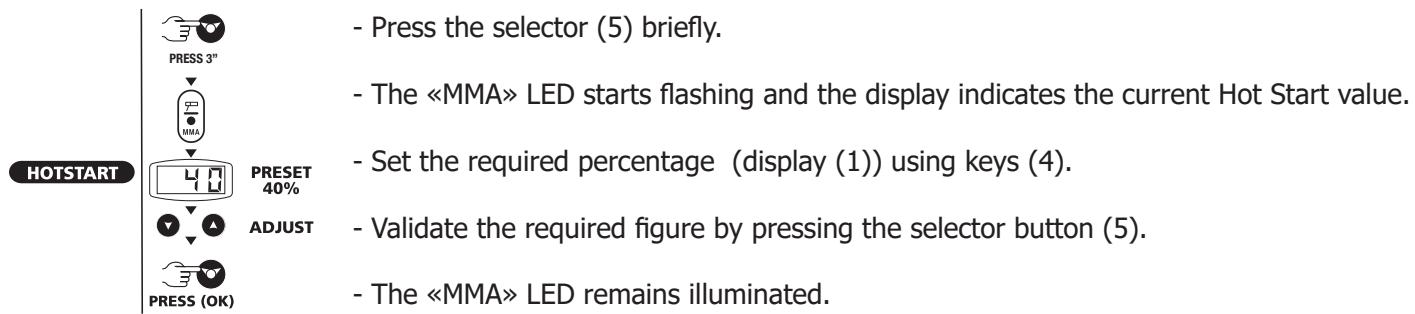
- Your machine is equipped with 3 specific functions :
Hot Start (adjustable mode, see below) increases the current at the beginning of the welding.
Arc Force increases the current in order to avoid sticking when the electrode enters the weld pool.
Anti Sticking allows you to easily remove your electrode without damaging it in case of sticking.
Selection of MMA Mode and intensity setting :
- Select the MMA position (2) with the selector (5) until the MMA indicator illuminates.
- Adjust the desired current (display (1)) using the key (4).
Hot Start adjustment
Hot Start is adjustable from 0 to 60% within the limit of 160A.
Advice: low Hot Start: for thin metal sheets – high Hot Start for metals that are difficult to weld (dirty or oxidized parts).
To adjust the Hot Start follow these steps:
TIG WELDING (TIG LIFT MODE)
The DC TIG welding requires a protective gas (argon).
Follow the steps below:
- Connect the earth clamp to the positive socket (+) .
- Connect the torch to the negative socket (-), the DINSE connector and the gas connector.
- Connect the gas pipe from the rear of the welder to the flowmeter of the gas cylinder
- Select TIG mode (3) using the selector button (5), press until the TIG indicator illuminates..
- Adjust the desired current (display(1)) using the keys (4), according to the thickness of the metal workpiece (30A / mm).
- Set the gas flow on flowmeter.
- To start
a- Touch the electrode on the welding workpiece.

b- Raise the electrode to between 2 - 5 mm from the workpiece.
- When finished : Release the trigger, downslope, post-gas.
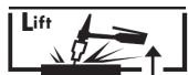
Adjustment of downslope
Function activation:
This function allows the user to adjust the time required at the end of welding for the gradual decline in the welding current until the arc stops. This function helps to avoid cracks and craters at end of welding.
To activate it, proceed as follows:
1- Press the selector button (5) for 3 seconds.
2- The TIG indicator starts flashing and the display indicates the current downslope time
3- Set the automatic arc downslope you wish from 0 to 10 sec (display(1)) using key (4).
4- Validate your choice pressing button (5). The TIG indicator remains illuminated.
Recommended combinations / Electrode grinding
| ↓ ↑ | Current (A) | Ø Electrode (mm) | Ø Nozzle (mm) | Flow rate (Argon L/mn) |
| 0.3 - 3 mm | 5 - 75 | 1 | 6,5 | 6 - 7 |
| 2.4 - 6 mm | 60 - 150 | 1.6 | 8 | 6 - 7 |
| 4 - 8 mm | 100 - 200 | 2 | 9.5 | 7 - 8 |
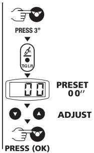
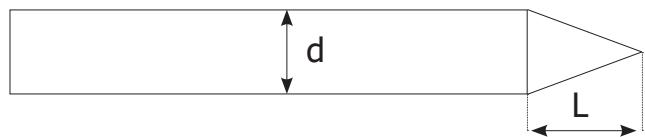
To optimise the welding process, it is recommended to grind the electrode prior to welding as described in the diagram below:
L = 3 × d for a low current
L = d for a strong current
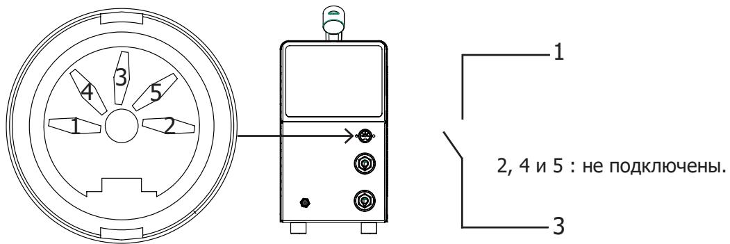
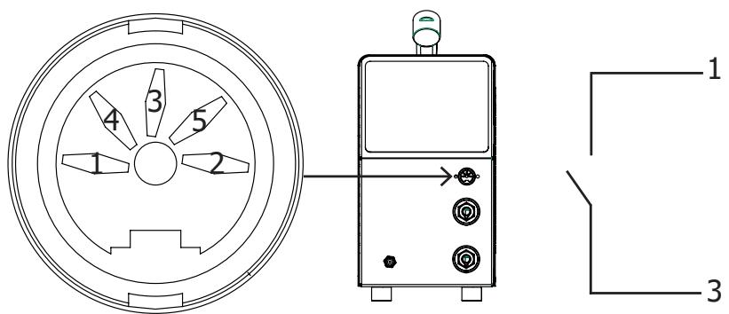
DIN connector - Torch command
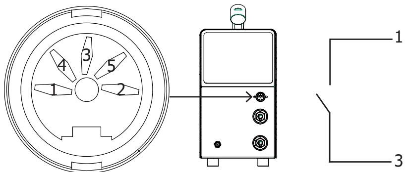
2, 4 & 5 : not connected
TROUBLESHOOTING
| Anomalies | Causes | Remedies | |
| MMA-TG | The device does not deliver any current and the yellow indicator lamp of thermal defect (6) lights up. | The welder thermal protection has turned on. | Wait for the end of the cooling time, around 2 minutes. The indicator lamp (6) turns off. |
| The display is on but the device does not deliver any current. | The cable of the earth clamp or electrode holder is not connected to the welder. | Check the connections. | |
| If, when the unit is on and you put your hand on the welding unit's body, you feel tingling sensation. | The welding unit is not correctly connected to the earth. | Check the plug and the earth of your electrical network. | |
| The display is on but the device does not deliver any current. | The cable of the earth clamp or electrode holder is not connected to the welder. | Check the connections. | |
| When starting up, the display indicates - - - . | The voltage is not included in the range (230 V +/-15%) | Have the electrical installation checked. | |
| TIG | Instable arc | Default coming from the tungsten electrode | Use a tungsten electrode with the adequate size |
| Use a well prepared tungsten electrode | |||
| Too important gas flow rate | Reduce gas flow rate | ||
| The tungsten electrode gets oxidised and tern at the end of welding. | Welding zone | Protect welding zone against air flows | |
| Default coming from post-gas or the gas has been stopped preamably. | Check and tighten all gas connections. Wait until the electrode cools down before stopping the gas. | ||
| The electrode melts | Polarity error | Check that the earth clamp is really connected to + | |
WARRANTY
The warranty covers faulty workmanship for 2 years from the date of purchase (parts and labour).
The warranty does not cover:
- Transit damage.
- Normal wear of parts (eg. : cables, clamps, etc..).
- Damages due to misuse (power supply error, dropping of equipment, disassembling).
- Environment related failures (pollution, rust, dust).
In case of failure, return the unit to your distributor together with:
- The proof of purchase (receipt etc ...)
- A description of the fault reported.
Hot start & Arc force regulables:
I3MeHeHnI pEmoHT, He yka3aHHbIe B 3ToI nHCTpyKcUN, He DoJXhbl 6bITb IpeDpnnHrTbI.
Ipn3BODInTeJIb He HecET OTBeTCTBHeHOctn 3a TpaBMbl N MaTePnaJIbHbIe IOBpeXdEHHra CBr3aHHbIe C HECOTBTCTBYIOUIM DaHHo INCHCTpyKcN INCNoJIb3OBAHnEM annapapaTa.
B cnlyuae npo6JIeMbI nII comHeHn, o6paTntecb K KBaIIuΦnUpOBaHHOMy CneuaJIncTy dIy npaBnIbHOrO IcNoJIb3OBAHnY yCTaHOBKn.
OKPYKHAOLJAR CPEDA
3To 06OpuydoBaHne doJxHo 6bIt hncOJIb3oBaHO nckJIIOUHTeJIbHO IJI CBaOpUHbIX pa6OT, orpaHnUBAraCy yka3aHnIIM3aBOIDcKoT Ta6JIuCKN H/INn INCTpyKcII. Heo6XoDIMO CO6JIIOdaT bIupeKTNBbl IO MEPAM 6e3OnacHOCTN. B cIyueae HeaAeKBaTHoro nn OnaCHO rCNOJb3OBAHn IPOIN3BOdTeJIb HE HeCEt OTBETCTBEHHOCtN.
AnnapaTdoJKeH6bITb yCTaHOBLeH B NOMEeHnN 6e3 PbIIN, KNCIObTI, BO3rOpaEMbIX ra3OB, INI dpynx Kopp03nHbIX BeueCTB. TaKne JxycIOBnD oJXhbl 6bITb co6JIIODeHbl dIy erO xpaHeHn. Y6eIInTeCb B npncytCTBm BcHTnJIaunn ppi nCNOJIb3OBAHn annapata.
Tempepatrphe ppeJIbI:
1000M BbICOTbI HaD ypoBHeM Mopra (3280 cyTOB).
INHINBNUdYAlbHAp 3AUHTA N 3AUHTA OKPYXeHn
DyroBaB CaBpKa MoKet 6bIb ONaCHO N BbI3BaTb TJaKeIbIe I daXe CmeptJIbHbIe paHeHn.
Cbapouhble pa60tI NOdBepraIOT NOLB3OBATeJIa BO3dEICTBIO ONaCHORIO nCTOUYHka TeNla, CBeTOBOrO n3JIyUeHnA yTn, 3JIeKTPOMarHTNbIX POJIe (OCo6OE BHNMaHne LInzam, IMeIoUIm 3JIeKTPOKApDIOCTMByJrTop), CINbHOMy UyMy, BvIDJeHnAm ra3a, a TAKKe MOrY CTaTB pPruHOnI NOPaKeHnEA 3JIeKTPnueCKmTOKOM.
YTo 6bI npabnIbHO 3aunITnb Ce6r n 3aunITnb OkpykaOuixx, co6JIouaTe cneDyUoune npabnla 6e3onacchoctn:

YTo6bI 3aunTntb Ce6r OTOxKOrB nOblUyehn npn pa6oTe c annapaTOM, HadeBaIe cyxu pa6oyuO 3aunTHyIO OdekJy (B XopoWem COCToAHn) n3 OrHeynopHoi TkaHn, 6e3 OTbOpOTB, KOtopa NOKpbIBaET PONHOCTbIO BCE TENo.

Pa60taIte B 3aunTHbIX pykabucax, o6ecneuBaIOUe 3JeKtpo- I TepMON3OJaUIO.

NcnoB3yIte cpeDCTBa 3aunTbI DnA CBAPKn N/nnn IJem DnA CBAPKn COOTBeTCTBYIOeero ypOBHn 3aunTbI (B 3aBNCIMOCtN OT NcnoJIb3OBAHn). 3aunTIte rna3a npn Onpaunx Ounchk. HoWeHne KOHTaKTHbIX LnH3 BocnPeeaaetcra.
B HeKoTOpbIX Clyuayx Heo6xoJIMO OkpyKInTb 30Hy OrHeynOpHbIMN 7ToPamN, YTO6bl 3aIHTb 3OHy CBapKn OT Lyuei, 6pbI3r i NaKeJIeHHoro IJaKa.
Ipeynpeinte okpykaioxnx He cmoTpeb Ha nyu n o6pa6aTbIbAemble deTaIIn HaeBaTb 3aunTHyIO pa6ooyo odexky.

Hocnte HayuHnKn npOTNB uMa, ecIn CBapOHyb npoceC DocTHrae 3BYKOBOrO ypOBHr Bblwe Do3BOJIeHHORO (3TO JxE OTHOCITcKo BCem IuCaM, HxOJaIUMcB 30He CBapKn).
Hnkorga He ChmMaTe 3aunTHbI KOpNc C cnCTeMb OXlaJxDeHn, KOrda NCTOuHk NOd HapjKeHneM.
Ipon3BODInTeJI He HecET OTBeTCTBeHHOCTN B Clyuae HecuaeTHoro Clyuay.
ToIbKO uTO CBapeHHbIe DeTaNr ropRn mOryt Bbl3BaTb OXoRn npn KOHTaKTe C HmN. Bo BpeM TeXo6cIyXKBaHnra RopeiKn nIN 3NeKTPOdoepXaTeJRA6eDITeC, yTO OHN DOCTaTOUHO OxJaININCb N IOdoXdnte Ka K MInHMym 10 MNHyT nepei Haayanom pa6OT. Pn iCNoJIb3OBaHnri RopeiKn c XnIDKOCTHBIM OxJaXdHeHem CNCTema OxJaXdHeHn DOnkHa 6bItb BKlIOyeHa, yTO6bI He oBKeYbcr XnIDKOCTbIO.
OueHb BaxHo 0630napntb pa6ouyu 30Hy nepeD TeM, KaK ee poknHyTb, YTO6bl 3aunHTNb IIODeI IN MMyuiceCTBO.
CBAPOHbIe IbIM IΓA3
BbIeJIeMbIe npCsbAPKe IbIM, ra3 n PbIb OaChbl dJe 3OpOBBy. BeHTnJIauny DoJXHa 6bITb DOCTaTOHOr, mOKeT nOTpe6oBaTbcra DOnOJIHInTeJbHna NJaCa y Bo3dYxa. PpN HeNoCTaTOUHO BHTnJIaun MoxHo BOCNoJIb3OBAtbcMAckO CBAPuKka-pecnnpaTOPOM.
PpOBepbTe, UTo6bI BcAcBHaHne BO3dYxa 6bIIO 3ΦΦeKTHnBbIM B COOTBETCTBnC HOpMaMn 6e30NaCHOCTn.
БудTe BHNMaTeJIbHbI: CBapka B He6OJIbXn XnomeUeHnX Tpe6yeT Ha6JIIODeHnHa 6e3OnaChOM paCtOAHn. Kpome ToR, CBapka HeKOTOpbIX MeTAnIOB, CoDEPkaUx NCINHeU, KaDMn, ZInK, pTyTb NII dAxe 6epnlln, MoKeT 6bITb Upe3BbUaHNO BpeHNo. CLeNyET OuchTntb OT Jnpa DeTaTI nepe CBapKOi.
YCTAHOBKA IN PPNHUNI DEICTBNA
Для поученя ONТИмальных Habtpoek n3delenpekOMeHnyetcЯСпОЛьЗOBaTb CBapOчные Ka6elen, NOCTABLAЯEMble B KOMПLEKTEC yCTpoICTBOM.
ОпИСАНе ANПAPATOB
PROTIG 160 DC LIFT yBnIeTcMaIor6aBapHTbIM CBAPoHbIM INHBepTOpOM CO BCTPOeHHbIM BEHTNJrTOpOM dJIa CBAPK NJIeKTPoDc M o6Ma3KO (MMA) n TyroPnA8kMm 3JIeKTPoDc (TIG Lift) Ha NOCTOAHOM Toke (DC). Oh pa6oTaet Ha 3JIeKTPnueckom PnTahnn, OJHOa3Hom B 230B. PnCsbAPKe MMA aannapat No3BOJare T bAPuTB IIObIM BvIDOM 3JIeKTPoDa: C pUInIOBoi OB6Ma3KO (JIeKTPoDbI DJIa CBAPK Na NepemEHOM Toke), C OCHOBHO OB6Ma3KO (JIeKTPoDbI DJIa CBAPK Na NocToAHNOM Toke), 3JIeKTPoDAmN DJIa CBAPK UyTuHa, 3JIeKTPoDAmN DJIa CBAPK HEPXABeHOSei CTaII N dp. B PexKIme Tig, OH BapNT 6Obl7uYIO uactb MeTALIOB 3a NCKLIouHeHEm aIIOHMHNIA I erO cPiABOB. OH MoXET pa6oTaTb OT 3JIeKTPoreHepaTopa (230B+-15%).
Описанne OБOPУДOBАнna (I)
1-KoHHeKToBpI dIra3aHa ropeJIke
2-「He3doIoJoxKnteJbHOnIpoJrphOCTn
3-「He3do OtpuataeJbHoi nojapHOCTN
4-KoHHeKTop TpIrgepa
5- Panaelb ynpablenia
6- 山Hyp nHTaHn (2.2 m)
7- PoiKJIIOUeHne ra3a
HHTEPΦEIC YEJIOBEK/MAUINHA (IHM) (II)
- Bb6paTb I03nHMO MMA (2) c nOoBIO KHOIKN (5), Haxab Ha He noka He 3aRopntbc JAmnoUka MMA
- OTPeryIInpoBaTb JKeIaEmyU INHTeHcNBHOCTb (INHdNkaTOp (1)) c nOMOuBIO KHOJOK (4).
Perylnpyemble Hot start:
CBAPKA TIG LIFT (PEXKIM TIG) (APROHOДУГОВА CBAPKA)
Cbapka TIG DC (npn noctoHHom Toke) Tpe6yeT nCnoIb3ObaHna 3aunTHoro ra3a (AproH).
KoHHeKToP KypkoBOrO ynpaBLeHnA
HENCINPABHOCTb, PIPNUH, YCTPAHEHNE
WAARSCHUWING - VEILIGHEIDSINSTRUCTIES
ALGEMENE INSTRUCTIES

INSTALLATIE VAN HET APPARAAT
Toorts contro connector
SALDATURA AD ELETTRODO RIVESTITO (MODALITÀ MMA)
SALDATURA TIG LIFT (MODALITA TIG)
*The duty cycles are measured according to standard EN60974-1 à 40°C and on a 10 min cycle.
While under intensive use (> to duty cycle) the thermal protection can turn on, in that case, the arc switches off and the indicator switches on.
Keep the machine's power supply on to enable cooling until thermal protection cancellation.
The welding power source describes an external drooping characteristic.