USER MANUAL 400M² 18V STERWINS

PRODUKTINFORMATIONEN

PREISINFORMATIONEN

VERFÜGBARKEITEN

TRACK &TRACE
- Safety regulations
- Layout and items supplied
- Intended use
- Technical data
- Starting up
- Operation
- Cleaning, maintenance and ordering spare parts
- Storage
-
Transport
-
Disposal and recycling
-
Indicators on the charging station and troubleshooting
- Indicators on the robot lawn mower and troubleshooting
- Charger indicator

Danger! - Read the operating instructions to reduce the risk of injury.
Warning: never allow children, persons with reduced physical, sensory or mental capabilities or lack of experience and knowledge or people unfamiliar with these instructions to use the machine, local regulations may restrict the age of the operator.
Warning: not to allow children to be in the vicinity or play with the machine when it is operating.
Warning signs must be put around the work area of the product if it operates in public areas. The signs must have the text that follows:
Warning!
Automatic lawn mower! Keep away from the machine! Supervise children!
GB
Danger!
When using the equipment, a few safety precautions must be observed to avoid injuries and damage. Please read the complete operating instructions and safety regulations with due care. Keep this manual in a safe place, so that the information is available at all times. If you give the equipment to any other person, hand over these operating instructions and safety regulations as well. We cannot accept any liability for damage or accidents which arise due to a failure to follow these instructions and the safety instructions.
1. Safety regulations
The corresponding safety information can be found in the enclosed booklet.
Warning!
Read all the safety information, instructions, illustrations and technical data provided on or with this power tool. Failure to adhere to the following instructions may result in electric shock, fire and/or serious injury.
Keep all the safety information and instructions in a safe place for future use.
Explanation of the symbols used (see Fig. 14)
A. WARNING - Read the operating instructions before you start using the machine.
B. WARNING - Keep a safe distance away from the machine when it is in operation.
C. WARNING - Always actuate the locking mechanism before carrying out any work on the machine or before lifting the machine. CAUTI-ON - Do not touch rotating blades
D. WARNING - Do not ride on the machine. CAUTION - Do not touch rotating blades
E. Protection class II (double-insulated)
F. Store the battery only in dry rooms with an ambient temperature of +10^ to +40^ . Place only charged batteries in storage (charged at least 40% ).
G. Protection class III
H. Slow fuse 2 A
I. For use in dry rooms only.
J. WARNING: To charge the battery, use only the removable power supply unit NT24/1 A / PS24/1 A delivered with this tool.
K. Guaranteed sound power level
Important!
Always pull out the power plug and disconnect the perimeter wire from the charging station during a storm.
2. Layout and items supplied
2.1 Layout (Fig. 1/2)
- Robot lawn mower
- Control panel
- STOP button / release button for the display cover
- Cutting height adjustment facility
- Rain sensor
- Carry-handle
- Main switch
- Rear wheel
- Battery compartment cover
- Blades
- Blade plate
- Front wheel
- Power supply unit (cable)
- Fastening peg
- Fastening screw
- Cable connector
- Spare blades
- Perimeter wire
- Charging station
- Charging pin
- LED indicator
- Hexagon key
- Display cover
- USB connection
- Ruler (for detaching)
2.2 Items supplied and unpacking
Please check that the article is complete as specified in the scope of delivery. If parts are missing, please contact our service center or the sales outlet where you made your purchase at the latest within 5 working days after purchasing the product and upon presentation of a valid bill of purchase. Also, refer to the warranty table in the service information at the end of the operating instructions.
- Open the packaging and take out the equipment with care.
- Remove the packaging material and any packaging and/or transportation braces (if available).
- Check to see if all items are supplied.
- Inspect the equipment and accessories for transport damage.
If possible, please keep the packaging until the end of the guarantee period.
GB
Danger!
The equipment and packaging material are not toys. Do not let children play with plastic bags, foils or small parts. There is a danger of swallowing or suffocating!
Scope of delivery, assembly material and accessories (some not included):
Details of the scope of delivery can be found in the enclosed related information sheet.
- Robot lawn mower
Power supply unit (cable)
- Charging station
Fastening screws (4 pcs)
- Spare blades
Fastening pegs
- Perimeter wire
- Cable connectors
- Hexagon key
- Rechargeable battery
- Charger
Ruler (for detaching)
Original operating instructions
Safety information
Required aids (not supplied)
- Hammer
- Pair of pliers
Wire stripper
Spirit level (optional)
3. Intended use
The robot lawn mower is intended for private use, i.e. for use in home and garden environments and only for mowing lawns.
The equipment is allowed to be used only for its prescribed purpose. Any other use is deemed to be a case of misuse. The user/operator and not the manufacturer will be liable for any damage or injuries of any kind resulting from such misuse.
Please note that our equipment has not been designed for use in commercial, trade or industrial applications. Our warranty will be voided if the equipment is used in commercial, trade or industrial businesses or for equivalent purposes.
4. Technical data
Voltage 18V
Motor speed 3500 min
Protection . IPX4
Protection class . III
Weight 8.55 kg
Cutting width 18 cm
Number of blades 3
Max. gradient 35%
Sound power level L_WA 59.3 dB(A)
Uncertainty K 2.52 dB (A)
Cutting height
adjustment 20-60 mm; infinitely adjustable
Permissible length of perimeter wire ..max. 250 m
Perimeter wire cable antenna
Operating frequency band 0-148.5 KHz
Maximum transmission power ....67.05 dBuA/m
Power supply unit
Input voltage: 100-240 V ~ 50/60 Hz
Output voltage: 24 V DC
Output current: 1.5 A
Protection class: .II /回
Sound values were measured in accordance with the standards EN ISO 3744:1995 and ISO 11094: 1991.
Warning!
This equipment generates an electromagnetic field during operation. Under certain circumstances this field may actively or passively impede medical implants. To reduce the risk of serious or fatal injuries, we recommend persons with medical implants to consult their doctor and the manufacturer of the medical implant prior to using the equipment.
5. Starting up
Read the operating instructions fully before you start work on the installation of the robot lawn mower. The quality of the installation work affects how effectively the robot lawn mower works later on.
GB
5.1 How it works
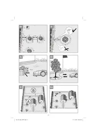
The robot lawn mower chooses its direction on a random basis. The robot lawn mower works its way over every area which is enclosed within the perimeter wire (18), so that the entire garden gets mowed. Whenever the robot lawn mower detects a correctly installed perimeter wire (18), the robot lawn mower turns about and drives in a different direction within the area. All zones that you wish to protect within the lawn area – e.g. garden ponds, trees, furniture or flower beds – must be cordoned off by the perimeter wire (18). The perimeter wire (18) must form a closed circuit. If the robot lawn mower bumps into an obstacle within the mowing area, it reverses and then continues mowing in a different direction (Fig. 3).
5.2 Sensors
Lifting sensor:
The robot lawn mower is equipped with a number of safety sensors.
If the robot lawn mower is raised at the back by more than 30^ from the ground or if a front wheel (12) loses contact with the ground, the robot lawn mower and the rotation of the blades (10) will be stopped immediately.
- Tilting sensor:
If the robot lawn mower tilts severely in any direction, the robot lawn mower and the rotation of the blades (10) are stopped immediately.
- Obstruction sensor:
The robotic lawnmower detects obstacles in its path. If the robotic lawnmower collides with an obstacle, the robotic lawnmower stops immediately and reverses away from the obstacle.
- Rain sensor:
The robot lawn mower is equipped with a rain sensor (5) to prevent the robot lawn mower from operating in the rain. The robot lawn mower returns to the charging station (19) when it detects rain and is completely recharged there. Once the rain sensor (5) is dry again, the robot lawn mower will stay in the charging station (19) for another two hours. Only then will it begin working again, provided it is still in an active time window. If the rain sensor (5) has been activated (this is recommended in order to exert less stress on the lawn), you will see a bright cloud in the display (50). If the sensor triggers, a dark cloud with rain drops will appear. Do not short-circuit the two metal sensors with metal or any other conductive material. This will impede the correct operation of the robot lawn mower.
5.3 Preparations
First, draw a sketch of your lawn. Include obstacles in your sketch and draw up a plan for how you intend to protect them. This will make it easier to find a good position for the charging station (19) and to lay the perimeter wire (18) around bushes, flower beds, etc. (Fig. 4). If the grass is taller than 60mm it has to be shortened first to avoid exposing the robot lawn mower to excessive load and adversely affecting its operating efficiency. Use a conventional lawn mower or trimmer to do this. It is recommended to cut the lawn below 30mm , using standard lawn mower, where the perimeter wire will be placed so that the wire is properly laying on the ground.
Remove all loose objects from the lawn which could get damaged by the robot lawn mower or damage the robot lawn mower itself. Have the following tools ready: A hammer, tongs, a wire stripper and a spirit level (optional).
Fitting the battery
A battery (A) from the Power-X-Change series is needed to operate the robot lawn mower. Important: Depending on the model of your robot lawn mower, it might not come complete with the battery (A). Open the battery compartment cover (9). Press the pushlock button of the battery (A) and push the battery (A) into the mount provided. Close the battery compartment cover (9) and make sure that it latches in place correctly (Fig. 10). To remove the battery (A), open the battery cover (9). Press the pushlock button of the battery (A) and pull out the battery (A).
5.4 Charging station
5.4.1 Position of the charging station
Determine the best position for the charging station first (19). An outdoor socket outlet is required which supplies a permanent supply of electricity so that the robot lawn mower works at all times. The charging station (19) must be placed on a flat area at the level of the turf. Make sure that the area is flat and dry. Select a position which is in the shade, because it is best if the rechargeable battery is charged up in a cool area. Also note that the perimeter wire has to be laid in a straight line for least 2m in front of the charging station (19) (Fig. 5a). Curves immediately in front of the charging station (19) could cause problems when docking for charging.
5.4.2 Localization of the charging station
When the rechargeable battery is almost empty, the robot lawn mower returns to the charging
GB
station (19) by following the perimeter wire (18) in a counterclockwise direction until it reaches the charging station (19). Make sure, therefore, that the charging station (19) faces in the right direction when you position it. (Fig. 5b)
5.4.3 Connecting the charging station to the power supply unit
- Before you connect the charging station (19) to the power supply, check that the mains power supply is 100 - 240V at 50 / 60Hz .
- Connect the power supply unit (13) directly to a socket outlet. Do not use the cable for any other use.
- Do not use the power supply unit if it is damaged (13). In the event of any damage to cables or the power supply unit (13), contact an authorized professional immediately for replacement.
- Do not charge up the robot lawn mower in a damp location. Do not charge up the robot lawn mower at temperatures above 40^ or below 5^ .
- Keep the robot lawn mower and the power supply unit (13) away from water, sources of heat and chemicals. Keep the cable of the power supply unit (13) away from sharp edges in order to prevent damage.
- Connect the power supply unit (13) to the charging station (19). (Fig. 5c) Do not install the charging station on an island, as the robot may not find its way back.
To charge up the rechargeable battery for the robot lawn mower straight away while you are still doing the installation work, first switch on the robot lawn mower with the main switch (7) and place the robot lawn mower in the charging station (19).
The robot lawn mower returns to the charging station (19) in each of the following situations:
- You send the robot lawn mower back manually.
The battery charge level drops below 30% .
The end of the daily work time has been reached.
The rain sensor has tripped.
- The robot lawn mower has become overheated.
- "Boundary cut" mode or „Spot mowing" mode was started outside the set work window and has been completed by the robot lawn mower. In these cases the robot lawn mower automa
tically runs along the perimeter wire (18) until it reaches the charging station (19).
When the robot lawn mower wants to return to the charging station (19), it will first look for the perimeter wire (18) and then move along the perimeter wire (18) in counter-clockwise direction. The LED indicator (21) on the charging station (19) lights up red while charging of the rechargeable battery is in progress.
When the LED indicator (21) on the charging station (19) turns to green, this indicates that the rechargeable battery is fully charged. Once it has been fully charged, the robot lawn mower resumes operation or remains in the charging station until the next work time window (19). If there is an obstacle on the perimeter wire (18) during the trip back to the charging station (19), the robot lawn mower will come to a stop in front of the obstacle after several attempts and will not be able to get back to the charging station (19). Remove all obstacles on the perimeter wire (18). If the temperature of the rechargeable battery exceeds 45^ , charging will stop in order to prevent damage to the rechargeable battery. Charging resumes automatically once the temperature has dropped again.
If the temperature of the controller of the robot lawn mower exceeds 65^ , the robot lawn mower will return to the charging station (19). Operation resumes in accordance with the settings once the temperature has dropped again.
If the rechargeable battery becomes empty before the robot lawn mower has returned to the charging station (19), it will not be possible for the robot lawn mower to start up again. Bring the robot lawn mower back to the charging station (19) and leave the main switch (7) switched on. The robot lawn mower will be charged up automatically.
5.5 Perimeter wire
IMPORTANT! Severed perimeter wires and consequential damages are not covered by the warranty!
5.5.1 Laying the perimeter wire
The perimeter wire (18) can be laid both on the ground and in the ground. The fastening pegs (14) can break when hammered in if the ground is hard or dry. Water the lawn before installing the perimeter wire if the ground is very dry.
Installation on the ground
Lay the perimeter wire (18) securely on the ground and fasten it with the supplied fastening pegs (14) if you do not intend to scarify
GB
or aerate the lawn any time later. You can still adjust the position of the perimeter wire again during the first few weeks of using the robot lawn mower. After a certain time, however, the perimeter wire will become overgrown with grass and no longer visible. Install the perimeter wire with a maximum distance of 1m between fastening pegs (14). Reduce the distance between the fastening pegs on uneven areas of the lawn. Avoid situations in which the wire is not actually on the ground. Make sure that the perimeter wire cannot be severed by the robot lawn mower.
Installation in the ground
Bury the perimeter wire in the ground at a depth of up to 5cm . This will prevent the perimeter wire (18) getting damaged during scarring or aeration, for example.
Important!
Keep a reserve of 1m of wire at the rear end of the charging station so that you can make corrections at a later time. Make sure to lay down the extra length outside of the lawn surface. Do not cross the wires.
5.5.2 Narrow points
If the lawn has a narrow point, your robot lawn mower will be able to operate there as long as the corridor has a width of at least 1.4m (80 cm between the perimeter wires) and a maximum length of 8 m. (Fig. 3).
5.5.3 Distance to the garden perimeter
When the robot lawn mower approaches a perimeter wire (18), the perimeter wire is detected by the sensors in the front of the robot lawn mower. Before the robot lawn mower turns about, however, it runs over the perimeter wire (18) by up to 30~cm . Please bear this in mind when planning your mowing area. (Fig. 6a)
5.5.4 Laying the wire in corners
Avoid laying the perimeter wire (18) at a right-angle (90^) in corners. To make sure that the robot lawn mower does not run too far beyond the perimeter wire (18), lay the perimeter wire (18) as shown in Fig. 6b.
5.5.5 Calculating the gradient of the lawn
The robot lawn mower can cope with gradients of up to 35% . You therefore need to avoid steeper gradients. The gradient can be determined on the basis of the height divided by the distance. (Fig. 6c)
Example: a / b = 35 cm/100 cm = 35%
5.5.6 Installation of the perimeter wire on gradients
The robot lawn mower can slip on gradients, especially if the grass is wet, and run over the perimeter wire (18) as a result. It is therefore recommendable to pay attention to the following points (Fig. 6d):
- In the area at the top of a slope, the perimeter wire (18) should not be installed on gradients over 35% . Make sure that a distance of 30~cm from obstacles and the edges of the lawn is maintained.
- In the area at the bottom of a slope, the perimeter wire (18) should not be installed on gradients over 17% . Make sure that a distance of 40~cm from obstacles and the edges of the lawn is maintained.
5.5.7 Driveways and paved paths
Cordon off raised pathways, areas surfaced with gravel or containing bark mulch, lower lying beds or other similar areas. Lay the perimeter wire (18) at a distance of at least 30~cm away. (Fig. 6e and 6g)
- Paths which are flush with the turf do not need to be cordoned off, because the robot lawn mower can simply run over them. You can also lay the perimeter wire (18) over paths. (Fig. 6f and 6g)
5.5.8 Perimeter islands
To protect obstacles in the mowing area, create perimeter islands. This will enable collisions with delicate objects, garden ponds, trees, furniture, flower beds, etc., to be avoided. (Fig. 6h and 6i)
- Roll out the perimeter wire (18) from the edges to the objects you want to protect.
- Secure the perimeter wire (18) with fastening pegs (14) in a clockwise direction around the object you want to protect. Be sure to keep a distance of 30cm with the perimeter wire from the object to be protected.
A distance of minimum 0,8m should be kept between the island and the external boundary wire.
- Completely enclose the perimeter islands and then run the perimeter wire (18) back to the point at which you left the edge of the lawn.
- Perimeter islands need to be at least 0.8m apart. Alternatively, combine the objects to make them into a joint perimeter island. (Fig. 6h)
The perimeter wires (18) to and from the pe
GB
rimeter island should be laid parallel and very close to one another. -Caution! Perimeter wires (18) must not cross over! -You should therefore fasten both the parallel perimeter wires (18) to the ground together using the same fastening peg (14). (Fig. 6i)
- The robot lawn mower will run over the two parallel perimeter wires (18) in the mowing area, but the robot lawn mower will stop where single perimeter wires (18) are laid.
5.5.9 Obstacles
- Obstacles with a height over 10cm (Fig. 6j)
Solid obstacles which are over 10~cm in height, e.g. trees, walls, fences, garden furniture, etc., are detected by the collision sensors. If the robot lawn mower collides with an obstacle, it will stop, switch off the mower unit, reverse and turn so that it can continue mowing in the other direction. Soft, unstable and valuable obstacles need to be protected by a perimeter wire island.
- Stones and low obstacles
Stones, rocks and low obstacles of less than 10cm in the mowing area need to be protected, because otherwise the robot lawn mower could run over them. If not, this could result in the robot lawn mower getting damaged or blocked.
Trees (Fig. 6k)
The robot lawn mower treats trees as obstacles. However, where any tree roots project above the ground to a height of less than 10 cm, the area in which they are located needs to be protected. This will prevent damage to the roots and to the robot lawn mower. Make sure that the minimum distance between the perimeter wire (18) and the obstacle is 30 cm.
5.5.10 Main area and secondary area (Fig. 6l)
A secondary area (B) designates a work area which is not directly connected to the main area (A), e.g. via a stretch of lawn or a path. To create a separate secondary area (B) lay the perimeter wire (18) from the main area (A) to the secondary area (B) and back again. The perimeter wire (18) to and from the secondary area (B) should be laid such that the return run is parallel and very close to the forward run. - Caution! Perimeter wires (18) must not cross over each other! - You should therefore fasten the parallel perimeter wires (18) to the ground jointly using the same fastening pegs (14).
To be able to mow the secondary area (B) you
must carry the robot lawn mower by hand into the secondary area (B). Start the required mowing program and select "Secondary area" in the submenu (see „Settings of the robot lawn mower"). When the robot lawn mower is in the secondary area (B) it will not try to follow the perimeter wire (18) towards the charging station (19) if the battery charge level is low. The robot will then need to be put back manually to the charging station for recharge
5.6 Connecting the charging station
Finish laying the complete perimeter wire (18) before you connect it to the charging station.
Keep an extra length of 1m of perimeter wire (18) at each end so that you can make further adjustments at a later time.
Using a wire stripper, remove a length of 10 to 15 mm of the insulation at the ends of the perimeter wire (18) for connecting to the charging station (19).
Pull out the power plug before you connect the perimeter wire (18) to the charging station (19).
The perimeter wire (18) laid to the front end of the charging station (19) must be run to the back via the cable holders on the underside of the charging station (19). Connect this perimeter wire (18) to the connection on the left (black). Then pass the rear perimeter wire (18) through the hole (stress-relief) in the connection area and connect it to the connection on the right (red) (Fig. 7a). The robot will then need to be put back manually to the charging station for recharge.
Important! Perimeter wires (18) must not cross over!
Then connect the power supply. The LED indicator (21) on the charging station (19) should light up green and stay on permanently. If the LED does not light up, check the connections first. If the LED lights up green but not permanently, read the "Indicators on the charging station and troubleshooting" table at the end of these operating instructions.
5.7 Switching on and checking the installation
As soon as the LED indicator (21) on the charging station (19) lights up green, the mowing area is ready for the robot lawn mower. Please check first that all the fastening pegs (14) on the perimeter wire (18) have been fully tapped in. Place the robot lawn mower about 3m to the rear of the charging station (19) in front of the perimeter wire (18).
GB
The robot lawn mower needs to be facing the perimeter wire (18) at an angle of 90^ (Fig. 7b). Switch on the main switch (7) (ON) (Fig. 8). Unlock the robot lawn mower by entering the PIN (see the section "Locking mechanism / PIN"). Press the "MODE" button (52). Then use the navigation buttons (55) to select the point "Back to station" and confirm with the "OK" button (56). Press the "START" button (53) and then close the display cover (23). The robot lawn mower will now follow the perimeter wire (18) in a counterclockwise direction. Observe the robot lawn mower during the complete trip along the perimeter wire (18) until it is back in the charging station (19). If the robot lawn mower has any problems at any points, correct the perimeter wire (18) if necessary and repeat the operation. The rechargeable battery of the robot lawn mower will now be fully charged. If any problems occur with docking, you may need to reposition the charging station (19) sideways until docking works without any problems.
To stop the robot lawn mower at any time, press the red STOP button (3). When you press the STOP button (3), the robot lawn mower will come to a stop and wait for further instructions.
5.8 Securing the charging station
Once the robot lawn mower is working properly and a suitable position for the charging station (19) has been found, the charging station (19) must be fixed in place using the fastening screws (15). Use the hexagon key (22) to secure the fastening screws (15) fully in the ground. (Fig. 7c)
5.9 Battery charge level indicator
Press the button for the battery charge level indicator. The battery charge level indicator indicates the charge state of the battery by means of 3 LEDs (Fig. 13b).
All 3 LEDs are lit:
The battery is fully charged.
2 or 1 LED(s) are lit:
The battery has an adequate remaining charge.
1 LED flashes:
The battery is empty, recharge the battery.
All LEDs blink:
The battery temperature is too low. Remove the battery from the equipment, keep it at room temperature for one day. If the fault reoccurs, this means that the rechargeable battery has undergone
exhaustive discharge and is defective. Remove the battery from the equipment. Never use or charge a defective battery.
Important!
When using a multi-Ah pack (e.g. 4-6Ah), always set the higher capacity. Thanks to the gentle charging and discharging of the robot lawn mower there is no need to use the lower capacity in order to extend the working life.
5.10 Charging the rechargeable battery with the charger
In normal operation the battery (A) of the robot lawn mower is charged via the charging station (19). For independent use of the battery (A) from the Power-X-Change series it can also be charged in the external Power-X-Charger. Important! - Depending on the model of your robot lawn mower, it might not come complete with the battery charger (Fig. 13a/Item B).
- Check that your mains voltage is the same as that marked on the rating plate of the battery charger. Insert the power plug of the charger (B) into the socket outlet. The green LED will then begin to flash.
- Insert the rechargeable battery (A) into the battery charger (B) (Fig. 13a).
- In the section entitled „Charger indicator“ you will find a table with an explanation of the LED indicator on the charger.
The rechargeable battery can become a little warm during the charging. This is normal.
If the battery pack fails to charge, check:
whether there is voltage at the socket outlet
- whether there is good contact at the charging contacts
If the battery pack still fails to charge, send
the charger
and the battery pack
to our customer service center.
To ensure that items are properly packaged and delivered when you send them to us, please contact our customer service or the point of sale at which the equipment was purchased.
When shipping or disposing of batteries and cordless tools, always ensure that they are packed individually in plastic bags to prevent short circuits and fires.
GB
To ensure that the battery pack provides long service, you should take care to recharge it promptly. You must recharge the battery pack when you notice that the performance of the device drops. Never allow the battery pack to become fully discharged. This will cause it to develop a defect.
6. Operation
6.1 Main switch
The robot lawn mower is equipped with a main switch (7). Use the main switch (7) to switch the robot lawn mower on (ON) and off (OFF) (Fig. 8). Once the robot lawn mower has been switched on, it is locked by a PIN.
6.2 Control panel
The robot lawn mower has already been programmed at the factory and default settings have been made for it. However, these can be changed if required. Even though the factory settings will be suitable for most gardens, you should still familiarize yourself with the available options nevertheless.
Explanation of the control panel with LCD (Fig. 9)
- LCD
- "SET" button
- "MODE" button
- "START" button
- "BACK" button
- Navigation buttons
- "OK" button
6.3 Cutting height adjustment facility
Important! Adjust the cutting height only when the robot lawn mower has been switched off. Do this by pressing the STOP button (3). The cutting height adjustment facility (4) allows the cutting height of the robot lawn mower to be set to infinitely adjustable settings between 20 and 60mm , which can be viewed on the scale.
If the grass is taller than 60~mm it has to be shortened to a maximum of 60~mm first to avoid exposing the robot lawn mower to excessive load and adversely affecting its operating efficiency. Use a conventional lawn mower or trimmer to do this.
After installation has been completed, the cutting height can be adjusted using the cutting height adjustment facility (4). Always start with a higher cutting height and reduce it in small steps until you reach the desired height.
6.4 Locking mechanism / PIN
The locking mechanism prevents the unauthorized use of the robot lawn mower without a valid code. You have to enter a personal four-digit security code for this.
Lock release
Before you start using the robot lawn mower, you have to enter the correct PIN (standard PIN: "0-0-0-0"). Enter the PIN with the help of the navigation buttons (55).
Standard PIN: New PIN:
0000
Changing the PIN
To change the PIN, proceed as follows.
- Unlock the control panel.
- First press the "SET" button (51) in order to make your settings.
- Use the navigation buttons (55) to navigate in the menu on the LCD (50) to the point "General information" and then ,PIN code".
- First enter the current PIN (standard PIN 0-0-0-0) with the help of the navigation buttons (55).
- Then use the navigation buttons (55) to enter your personal PIN.
- Confirm the settings you have just made.
- Repeat step 5. and step 6 in order to confirm the new PIN.
- Important! Make a note of the new PIN.
Requesting your PIN if you lose it
Have the receipt and the serial number of the robot lawn mower ready. You need them in order to get your PIN.
Version A:
- Press and hold the "SET" button (51) for 6 seconds in locked status.
- The PUK will now appear in the display (50).
- Contact the customer services team to obtain your PIN. Refer to the section „service information" for contact information's.
Contact information can be found in the „Service information" section
Version B:
- Connect an empty USB stick to the USB connection (24) as shown (Fig. 11).
- Switch on the main switch (7) (ON).
- The robot lawn mower will automatically save the PUK to your USB stick and will then end the operation with a beep.
GB
- Pull out the USB stick. Import the data from the USB stick to a computer. A text file (.txt) will have been created by the robot lawn mower. This file contains a PUK, a personal code. Please contact the customer services team to obtain your PIN.
6.5 Settings of the robot lawn mower
The main menu on the LCD (50) shows you the current date and time settings of the robot lawn mower, as well as the current charge level. At the same time the status of the rain sensor and of the wire signal and of the selected mowing program will appear in the toolbar. On the control panel you can use either the "SET" button (51) to make settings on the robot lawn mower or the "MODE" button (52) to start the robot lawn mower with various mowing programs. Use the navigation buttons (55) to go to the option where you want to make the settings. Press the "BACK" button (54) in order to exit the respective menu.
The "SET" button (51) can be used to make the basic settings on your robot lawn mower. Use the navigation buttons (55) to move to where you want to go and then use the "OK" button (56) to confirm or the "Back" button (54) to discard the settings you have made.
Schedule
Use the navigation buttons (55) to move to the day of the week for which you want to make the settings. In normal operating mode, the robot lawn mower will automatically begin to mow your lawn at the set time on the respective day. It is recommended to base the mowing time setting on 8 hours per day for 500m^2 as a guideline. The selected working time may need to be adapted to take account of the garden's size and complexity.
Zone
Where gardens have lots of angles, the robot lawn mower may have problems reaching every part of the lawn and mowing it completely. In this case you can select several starting points on the perimeter wire (18). This will enable the robot lawn mower to get to even those parts of your garden that are difficult to reach. The robot lawn mower will run the selected distance along the perimeter wire (18) and then start mowing in this part of the garden (Fig. 6m). Use the navigation buttons (55) to go to the point that you wish to change and enter the distance and frequency accordingly. The charging station (19) is automatically
defined as starting point 1. The two other starting points can be selected as you wish. For this you must measure the distance between the charging station (19) and the starting point in clockwise direction along the perimeter wire (18). With the frequency setting you decide how often the robot lawn mower starts its work from the charging station (19) or from the respective starting points.
Boundary cut
For a tidy lawn edge you can activate the "Edge mowing" setting. You can also set the lawn mowing frequency, i.e. the rhythm in which you want the edge of the lawn to be mowed at the beginning of the work window. In the standard setting the robot lawn mower will begin work on all 7 work days by first mowing along the entire perimeter wire.
Error log
From here you will be informed about the latest error messages concerning your robot lawn mower.
- Rain sensor
The rain sensor (5) can be programmed using this setting. The default factory setting for the sensor is "On". You can activate or deactivate the rain sensor (5) and set its delay time. The delay time defines how long the robot lawn mower continues to remain in the charging station (19) after the rain sensor (5) has dried.
Leaving the station
You can set how far and where the robot lawn mower travels when it reverses out of the charging station (19). First the robot lawn mower reverses the set distance before it turns into the area to be mowed or towards its starting point. Make sure that the set reversing distance does not cause the robot lawn mower to leave the area to be mowed.
General
- PIN code: You can replace the default PIN for the robot lawn mower with your own choice of PIN. To do so, proceed as described in the chapter "Locking mechanism / PIN". Important! Make a note of the new PIN.
- Date & time: Use the navigation buttons (55) to go to the point that you want to change and make the settings accordingly.
- Language: Use the navigation buttons (55) to activate the language that you want.
- Software version: The current version of the robot lawn mower software is noted here.
GB
Use the navigation buttons (55) to go to the mowing program that you want to start. You can always choose between "Main area" and "Secondary area". More details of the two areas can be found in the section "Before using for the first time" under "Perimeter wire".
Mowing
When you start the robot lawn mower to mow the lawn, the mower will switch to normal operating mode with the set time schedule.
Boundary cut
Place the robot lawn mower close to the perimeter wire (18) or start the mower while it is in the charging station (19). With its mower unit activated, the robot lawn mower will follow the perimeter wire (18) in counter-clockwise direction until it reaches the rear of the charging station (19). Provided no work window is active, the robot lawn mower will then return to the charging station (19).
- Spot mowing
It may happen that your robot lawn mower fails to mow some spots sufficiently. Place the robot lawn mower at the spot in question and start the mower. The robot lawn mower will begin to mow the lawn in a spiral pattern until it collides with an obstacle or the perimeter wire (18). Provided no work window is active, the robot lawn mower will then return to the charging station (19).
Back to station
Send your robot lawn mower back to the charging station (19). The robot lawn mower will look for the perimeter wire (18) and follow it counter-clockwise to the charging station (19). The secondary area option does not exist in this case.
6.6 Controlling the robot lawn mower
Starting procedure
- Press the "STOP" button (3) and open the display cover (23) fully.
- Unlock the control panel (2).
- Use the "MODE" button (52) to select the mowing program and the respective work area you want.
- Press the "START" button (53).
- Close the display cover (23).
The robot lawn mower will now operate in accordance with the mowing time setting. During work time the battery charge level will appear on the LCD (50). Whenever the battery charge level drops to 30% , the robot lawn mower will return
automatically to the charging station (19).
Canceling the mowing operation
- To bring the robot lawn mower to an immediate stop, press the STOP button (3).
- Open the display cover (23) fully.
- Unlock the control panel (2).
- Press the "MODE" button (52) and select "Back to station" in order to send the robot lawn mower along the perimeter wire (18) and back to the charging station (19).
- Press the "START" button (53).
- Close the display cover (23).
STOP status:
When you press the STOP button (3), the robot lawn mower will adopt a STOP status. This will be indicated in the LCD (50). The robot lawn mower will interrupt its mowing until this STOP status is canceled.
When the control panel (2) is unlocked, a window will appear and ask if you want to cancel the STOP status. If you confirm, the status will be canceled. If you don't confirm, the robot lawn mower will remain stopped. If the robot lawn mower is started or returned to the charging station (19), the STOP status will be canceled likewise. Close the display cover (23).
7. Cleaning, maintenance and ordering spare parts
Hazard!
The equipment must be disconnected from the power supply (pull out the power plug and switch off the equipment by the main switch (7) (OFF) (Fig. 8) prior to performing any cleaning and maintenance work. Also take the battery out of the robot lawn mower.
Caution! Wear work gloves!
7.1 Cleaning
- Keep all safety devices, air vents and the motor housing free of dirt and dust as far as possible. Wipe the equipment with a clean cloth or blow it down with compressed air at low pressure.
- Do not clean the robot lawn mower with running water, particularly with high-pressure water.
Clean the equipment regularly with a damp cloth and some soft soap. Do not use cleaning agents or solvents; these may be ag
GB
gressive to the plastic parts in the equipment. Ensure that no water can get into the interior of the equipment.
- For best results, clean the robot lawn mower with a brush or rag.
- Check the freedom of movement of the blades (10) and the blade plate (11)
- Use cleaning product for metal or very fine abrasive paper to clean the charging contacts on the robot lawn mower (1) and the charging station (19). Clean them in order ensure efficient charging.
7.2 Maintenance
- Worn or damaged blades (10) and their fastening screws must always be replaced as a set.
- Replace excessively worn or damaged parts immediately.
In order to ensure that you enjoy the equipment for many years to come, all screwed parts, as well as the wheels and axles, should be cleaned and lubricated.
- Keeping your robot lawn mower in good condition not only ensures a long lifespan and high performance, but also enables the equipment to thoroughly cut your grass with minimal effort.
- The blades (10) are subject to more wear and tear than any other component. Therefore, routinely check the condition of the blades (10) and make sure that they are tightly fastened. An excessively vibrating robot lawn mower can indicate that the blades (10) are damaged or have become deformed from striking an object. If the blades (10) are worn or damaged, they must be replaced immediately.
- Check the appearance of the cut lawn at regular intervals. The grass will not be cleanly cut if the blades are not sharp. This can result in the surface of the lawn drying out easily and turning brown. It is important therefore to change the blades regularly in order to obtain a clean and straight cut.
- Check the bottom of the robot lawn mower for dirt at regular intervals. Clean your robot lawn mower regularly. Remove heavy soiling immediately.
-
Heavy soiling of the robot lawn mower is possible in the first weeks of using it for the first time after a conventional law mower had previously been used. In these first few weeks you should check the bottom of your robot lawn mower more often.
-
Shorten the lawn only in small steps in order to prevent heavy soiling.
- There are no other parts inside the equipment which require maintenance.
The robot mower's blades should be replaced every 3 months. Always replace the blades in a complete set!
Clean the robot lawn mower regularly. The robot lawn mower should be cleaned every 2 weeks at the latest. This also depends however on the distance covered by the mower and on the weather conditions.
7.2.1 Replacing the blades
Only replace the blades with genuine blades, as this will ensure top performance and safety.
The robot lawn mower is equipped with three blades (10) fitted to a blade plate (11). These blades (10) have a service life of up to 3 months (if they do not strike any obstacles). Please replace all three blades (10) at the same time to ensure that there is no possibility of any impairment to the efficiency and balance of your equipment.
To change the blades (10), proceed as follows (Fig. 12) - Caution! - Wear work gloves:
- Use a screwdriver to block the rotation of the blade plate (11). Do this by inserting the screwdriver through the holes in the blade plate (11) and the protective ridge.
- Undo the fastening screws
- Remove the blades (10) and replace them with new ones. Always replace all three blades (10) as a set.
- Then retighten the fastening screw. Check that the new blades (10) are able to rotate freely.
Perform a general inspection of the robot lawn mower at regular intervals and remove any deposits which may have accumulated. At the start of each season, ensure that you check the condition of the blades (10). If repairs are necessary, please contact our customer service center. Use only genuine spare parts.
7.2.2 Software update
If you want to update the software, copy the new software to an empty USB stick (format the USB stick first if necessary). Make sure that the rechargeable battery is fully charged before you carry out the following steps.
- Place the robot lawn mower in the area to be mowed. The robot lawn mower must not be in the charging station during the software
GB
update.
- Connect a USB stick to the USB connection as shown in the illustration. (Fig. 11).
- Switch on the main switch (7) (ON).
- The robot lawn mower will now start updating the software and will display the current status.
- Pull out the USB stick and restart the robot lawn mower with the main switch (7).
For the new software, contact our customer service or visit our websitehttps://www.einhell-service.com/en_DE/page/sterwins-robot-lawnmower
7.2.3 Repairing the perimeter wire
If the perimeter wire (18) gets severed at any point, use the supplied cable connectors (16) to repair it. To do so, insert both ends of the severed perimeter wire (18) into the cable connector (16) and squeeze it together with the help of a pair of pliers. Connect the power plug to the socket outlet. Then check whether it is working properly by checking the LED indicator (21) on the charging station (19).
7.3 Ordering spare parts
Please provide the following information when ordering spare parts:
Type of unit
- Article number of the unit
ID number of the unit
- Spare part number of the required spare part For our latest prices and information please go to https://www.einhell-service.com/en_DE/page/sterwins-robot-lawn-mower
Replacement blades Art. No.: 34.140.20
Important:
For the exploded view and bill of material, please refer to our Einhell website.
Spare parts available of this Product is 10 Years, after the last date of purchase.
8. Storage
Fully charge up the rechargeable battery before putting it into storage over winter and switch off the robot lawn mower at the main switch (7) (OFF). Take the rechargeable battery out of the equipment. Disconnect the power supply unit (13)
from the power supply and the charging station (19).
The perimeter wire (18) can be left outdoors over winter. However, make sure that the connections are protected against corrosion. To do so, disconnect the connections of the perimeter wire (18) from the charging station (19).
Store the equipment and accessories out of children's reach in a dark and dry place at above freezing temperature. The ideal storage temperature is between 5 and 30^ . Store the equipment in its original packaging.
9. Transport
- Switch off the equipment at the main switch (7) (OFF). (Fig. 8).
- Fit the shipping protectors, if any.
- Protect the machine from damage and the strong vibrations that can occur particularly when transporting in vehicles.
- Secure the machine against slipping and tipping over.
- Carry the robot lawn mower by the carryhandle (6) with the blade plate (11) facing away from your body.
10. Disposal and recycling
The equipment is supplied in packaging to prevent it from being damaged in transit. The raw materials in this packaging can be reused or recycled. The equipment and its accessories are made of various types of material, such as metal and plastic. Never place defective equipment in your household refuse. The equipment should be taken to a suitable collection center for proper disposal. If you do not know the whereabouts of such a collection point, you should ask in your local council offices.
11. Indicators on the charging station and troubleshooting
| LED indicator (21) | Description | Solution |
| Off | - No power supply | - Check the power supply |
| Lit up green | - Ready for mowing
- Rechargeable battery is ful-ly charged
- Perimeter wire (18) connec-ted | - If the boundary wire connection to the charging station is correct, refer to the troubleshooting of the robotic lawn mower if there is any other problem. |
| Flashing green | - Perimeter wire (18) is se-vered | - Inspect the perimeter wire (18) for a break.
1. Check the connection at the back of the charging station, make sure both wire ends are properly naked and fully inserted inside each plugs.
2. Check for damaged boundary wire around the lawn (the wire doesn't need to be completely cut to stop the signal)
3. If step 1 and 2 are ok, disconnect the two ends of the boundary wire from the charging station. Connect a 5m length wire to the charging station and lay it down temporarily on the ground.
a) Confirm if the light is constant green, if yes (constant green) => it means that the signal is restored when using another wire. Perform deeper inspection to detect where the boundary wire is damaged or broken. If using some connectors, make sure, the wires are properly naked and fully inserted and that the connectors is properly clamped.
b) If light is still blinking => check the con- nection at the back of the charging station, make sure both wire ends are properly naked and fully inserted inside each plugs. If problem remains, contact your Aftersales service. |
| Lit up red | - Rechargeable battery is charging | - Wait until the rechargeable battery is fully charged. |
12. Indicators on the robot lawn mower and troubleshooting
Fault messages of the robot lawn mower in the LCD display (50)
| Fault | Possible cause | Remedy |
| No signal | - Perimeter wire is not properly connected
- No power supply
- The perimeter wire (18) is severed | Check whether the LED indicator (21) at the charging station (19) is lit up green
- Make sure that the perimeter wire (18) has been laid correctly and centrally under the charging station (19).
- Check the position of the charging station (19). |
| Outside border | - Perimeter wire is not properly connected
- The robot lawn mower is out-side the mowing area | - Make sure that the perimeter wire (18) has been laid correctly and centrally under the charging station (19)
- Check that the robot lawn mower is inside the mowing area. |
| Battery error | - There is a battery error on the robot lawn mower
- The rechargeable battery does not charge up
- The rechargeable battery has reached the end of its service life | - Make sure that the rechargeable battery has been correctly fitted
- Check whether the main switch (7) is ON while the robot lawn mower is in the charging station (19).
- Check the position of the charging station (19) Replace the rechargeable battery if necessary. As for all devices using a battery, the number of charging cycles is limited. Go back to your Stores Aftersales service to purchase a new battery pack. |
| Battery temperature error | The temperature of the rechargeable battery is too high/low or the controller is overheated
- If the battery temperature exceeds 65°C, the robot lawn mower will return to the charging station (19)
- If the battery temperature exceeds 45°C or drops below 0°C, charging will be stopped and the robot lawn mower will wait at the charging station (19) | - Set the work time in summer to the early hours of morning and avoid running the robot lawn mower during the hours of the day when it is hot.
- After the rechargeable battery or controller has cooled down to the permissible temperature range, the robot lawn mower automatically returns to programmed operation.
- During wintertime or when the outside temperature is below 5°C, take the robot to a warm and dry area. |
| Mower lifted | - The lifting sensor has been continually tripped for 10 seconds | Press the STOP button (3) to open the display cover (23). Restart the mowing operation via the control panel (2):
- If this fault occurs frequently, check the mowing area for obstacles taller than 10 cm and either remove them or cordon them off from the mowing area with perimeter wire (18). |
GB
Fault messages of the robot lawn mower in the LCD display (50)
| Fault | Possible cause | Remedy |
| Mower blocked | - The obstruction sensor has tripped several times within one minute
- The obstruction sensor has been constantly activated for 10 seconds
- The obstruction sensor has tripped three times on the way back to the charging station (19) | Press the STOP button (3) to open the display cover (23). Restart the mowing operation via the control panel (2):
- Check whether the robot lawn mower is blocked by an obstacle or jammed between trees, bushes, etc. Remove the obstacle or avoid this area.
- If this fault occurs frequently, check the way in which the perimeter wire (18) has been laid. Pay particular attention to tight angles, corridors, fences, rocks, etc., and adjust the layout of the perimeter wire (18) if necessary.
- Check whether the grass is too tall and the robot lawn mower gets blocked. If this is the case, mow the grass with a conventional law mower to below 60 mm.
- Check also that the grass on the side of the boundary wire is not obstructing the robot movement while driving along the boundary wire, if necessary, trim the edges of your lawn.
- If this fault occurs on the charging station, ensure that the charging connector on the charging station and on the robot are cleaned. |
| Too close to garage | - The robot lawn mower was sent back too close to the charging station (19). | Press the STOP button (3) in order to open the display cover (23). Re-start the mowing operation on the control panel (2):
- The robot lawn mower should be sent back to the charging station (19) at a minimum distance of 2 m. |
| Rolling over | - The robot lawn mower was constantly tilted for 10 seconds.
- The robot lawn mower has been tilted for a prolonged time in one direction. | Press the STOP button (3) to open the display cover (23). Restart the mowing operation via the control panel (2):
- Move the robot lawn mower to a level area and restart it.
- If the robot lawn mower has tilted because of a steep slope in the mowing area, adjust the perimeter wire (18) accordingly to avoid severe inclines. |
| Wheel slip | - The rear wheels (8) have lifted due to an obstacle.
- The rear wheels (8) can rotate freely due to an uneven lawn.
- The wheels are dirty or the ground is slippery. | Press the STOP button (3) to open the display cover (23). Restart the mowing operation via the control panel (2):
- Move the robot lawn mower to a level area and restart.
- Make sure the whee are cleaned, clean them with a brush if necessary.
- Repair the ground by filling the hole. |
GB
Fault messages of the robot lawn mower in the LCD display (50)
| Fault | Possible cause | Remedy |
| STOP button error | The display cover (23) is open but the STOP button (3) was not pressed. | Press the STOP button (3) to open the display cover (23). Restart the mowing operation via the control panel (2):
- Check whether the display cover (23) can be opened and closed freely with the STOP button (3).
- Check whether the STOP button (3) functions correctly. |
| PCB overtemp. | The temperature of the rechar-geable battery is too high/low or the controller is overheated
- If the battery temperature exceeds 65°C, the robot lawn mower will return to the charging station (19).
- If the battery temperature exceeds 45°C or drops below 0°C, charging will be stopped and the robot lawn mower will wait at the charging station (19). | - Set the work time in summer to the early hours of morning and avoid running the robot lawn mower during the hours of the day when it is hot.
- After the rechargeable battery or controller has cooled down to the permissible temperature range, the robot lawn mower will automatically return to the programmed operating mode |
| Rain | - The rain sensor (5) has tripped. | - Wait until the robot lawn mower has dried out.
- A detailed description of the sensor can be found in section 5.2. |
| Sensor fault | - The robot lawn mower was stopped due to a sensor er-ror | Switch off the main switch (7) (OFF) and then switch it back on (ON) again to restart the robot lawn mower. |
| Motor fault / motor overcurrent | - The robot lawn mower has come to a stop because of overcurrent in the motor or because of a motor fault | Switch off the main switch (7) (OFF) and then switch it back on again (ON) to restart the robot lawn mower.
- Check the height of the grass in the mowing area and, if necessary, mow the grass to below 60 mm using a conventio-nal lawn mower.
- Increase the cutting height. Always start with a higher cutting height and reduce it in small steps until you reach the desired height.
- Inspect the blade plates (11) and wheels for dirt and give these parts a thorough clean.
- Check the rear wheels and the blade plate (11) for blockages. If you are unable to remove the blockages, contact the res-pondible customer service center. |
| Breakdown | - The robot lawn mower was stopped due to an operating error | Switch off the main switch (7) (OFF) and then switch it back on again (ON) to restart the robot lawn mower. |
GB
Troubleshooting
| Fault | Possible cause | Remedy |
| The robot lawn mower comes to a stop in the mowing area. The robot lawn mower cannot be switched on: | - Battery voltage too low
- Fault in the power circuit or the electronic components | - Bring the robot lawn mower back to the charging station (19) for charging.
- Switch on the main switch (7) (ON).
- Contact your customer service center. |
| The robot lawn mower cannot move into the charging station. | - The charging station (19) is not installed correctly. | - Make sure that the LED indicator (21) on the charging station (19) is lit up green.
- Make sure that the perimeter wires (18) are connected at the charging station (19) and that the front perimeter wire (18) is laid in the middle underneath the charging station (19).
- Make sure that the charging station (19) is positioned correctly. |
| The robot lawn mower stops or travels out of control when near perimeter islands. | - The perimeter wire (18) has not been installed correctly around the perimeter islands. | - Adjust the position of the perimeter wire (18).
- Make sure that the perimeter wire (18) does not cross over itself. |
| The robot lawn mower is very loud. | - Damaged blades (10)
- A large amount of foreign bodies adhere to the blades (10)
- The robot lawn mower has started too close to obstacles
- Damaged blade drive or drive motor
- Other parts of the robot lawn mower are damaged | - Replace the blades (10). The 3 blades (10) must all be replaced together at the same time.
- The operating efficiency of the robot lawn mower is dependent on the sharpness of the blades (10). You should therefore ensure that the blades (10) are maintained in good condition.
- Switch off the robot lawn mower safely and wear work gloves while you clean the blades (10) in order to avoid getting cut.
- Arrange for the motor to be repaired or replaced by your customer service center. |
| The robot lawn mower stays in the charging station. The robot lawn mower keeps returning to the charging station | - Incorrect work time settings
- The rechargeable battery is empty
- The rain sensor has been triggered
- The battery temperature is high | - Check the work time settings.
- The robot lawn mower will begin and end its work in accordance with the set time window. Outside this time window the robot lawn mower stays in the charging station (19).
- Make sure that the rain sensor is cleaned and dry.
- Make sure the robot charging station is not exposed to direct sunshine. Install charging station cover if necessary (to be purchased separately). |
GB
Troubleshooting
| Fault | Possible cause | Remedy |
| The robot lawn mo-
wer comes to a halt
on the perimeter
wire and is unable
to get back to the
charging station. | - The battery is empty
- The length of the perimeter
wire (18) and therefore the
distance to the charging sta-
tion (19) is too great for the
battery being used. | - Remove all possible obstacles from the
perimeter wire (18). When you layout out
the perimeter wire (18), be sure to keep it
far enough away from any obstacles.
- Please use a battery with higher capacity.
- Important: When using a Multi-Ah battery
(e.g. 4-6 Ah), set the higher capacity.
Thanks to the gentle charging and di-
scharging of the robot lawn mower there is
no need to use the lower capacity in order
to extend the working life. |
IMPORTANT! Severed perimeter wires and consequential damages are not covered by the warranty!
13. Charger indicator
| Indicator status | Explanations and actions |
| Red LED | Green LED |
| Off | Flashing | Ready for use
The charger is connected to the mains and is ready for use; there is no battery pack in the charger |
| On | Off | Charging
The charger is charging the battery pack in quick charge mode. The charging times are shown directly on the charger.
Important! The actual charging times may vary slightly from the stated charging times depending on the existing battery charge. |
| Off | On | The battery is charged and ready for use. (READY TO GO)
The unit then changes over to gentle charging mode until the battery is fully charged.
To do this, leave the rechargeable battery on the charger for approx. 15 minutes longer.
Action:
Take the battery pack out of the charger. Disconnect the charger from the mains supply. |
| Flashing | Off | Adapted charging
The charger is in gentle charging mode.
For safety reasons the charging is performed less quickly and takes more time. The reasons can be:
- The rechargeable battery has not been used for a very long time.
- The battery temperature is outside the ideal range.
Action:
Wait for the charging to be completed; you can still continue to charge the battery pack. |
| Flashing | Flashing | Fault
Charging is no longer possible. The battery pack is defective.
Action:
Never charge a defective battery pack.
Take the battery pack out of the charger. |
| On | On | Temperature fault
The battery pack is too hot (e.g. due to direct sunshine) or too cold (below 0°C).
Action:
Remove the battery pack and keep it at room temperature (approx. 20°C) for one day. |
GB
Disposal
Power tools, rechargeable batteries, accessories and packaging should be sorted for environmental-friendly recycling.
Do not dispose of power tools and batteries/rechargeable batteries into household waste!
Only for EU countries:
According to the Directive 2012/19/EU on waste electrical and electronic equipment and its transposition into national law, power tools that are no longer usable, and, according to the Directive 2006/66/EC, defective or drained batteries must be collected separately and disposed of in an environmentally correct manner.
If disposed incorrectly, waste electrical and electronic equipment may have harmful effects on the environment and human health, due to the potential presence of hazardous substances.
Only for United Kingdom:
According to The Waste Electrical and Electronic Equipment Regulations 2013 (SI 2013/3113) (as amended) and the Waste Batteries and Accumulators Regulations 2009 (SI 2009/890) (as amended), products that are no longer usable must be collected separately and disposed of in an environmentally friendly manner.
The reprinting or reproduction by any other means, in whole or in part, of documentation and papers accompanying products is permitted only with the express consent of the Einhell Germany AG.
Subject to technical changes
GB
We have competent service partners in all countries named on the guarantee certificate whose contact details can also be found on the guarantee certificate. These partners will help you with all service requests such as repairs, spare and wearing part orders or the purchase of consumables.
Please note that the following parts of this product are subject to normal or natural wear and that the following parts are therefore also required for use as consumables.
| Category | Example |
| Wear parts* | Battery |
| Consumables* | Blades |
| Missing parts | |
- Not necessarily included in the scope of delivery!
In the effect of defects or faults, please register the problem on the internet at www.Einhell-Service.com. Please ensure that you provide a precise description of the problem and answer the following questions in all cases:
Did the equipment work at all or was it defective from the beginning?
Did you notice anything (symptom or defect) prior to the failure?
- What malfunction does the equipment have in your opinion (main symptom)?
Describe this malfunction.
GB
Warranty certificate
Dear Customer,
All of our products undergo strict quality checks to ensure that they reach you in perfect condition. In the unlikely event that this equipment develops a fault, please contact our service department at the address shown on this guarantee card. You can also contact us by telephone using the service number shown. Please note the following terms under which guarantee claims can be made:
- These guarantee terms apply solely to consumers, i.e. natural persons, who do not want to use this product in connection with either their commercial or other self-employed activities. These guarantee terms regulate additional guarantee services which the undermentioned manufacturer promises to buyers of its new products in addition to their statutory rights of guarantee. Your statutory rights of guarantee are not affected by this guarantee. Our guarantee is free of charge to you.
- The guarantee services cover only defects due to material or manufacturing faults on the new product which you have bought in the European Union from the undermentioned manufacturer and are limited to either the rectification of said defects or the replacement of the product, whichever we prefer. Please note that only equipment under the brand name "Professional" has been designed for use in commercial, trade or professional applications. For all other products the guarantee is invalidated if the equipment is used within the guarantee period in commercial, trade or industrial applications or for other equivalent activities.
-
Our guarantee does not cover:
-
Damage to the equipment caused by failure to comply with the installation/assembly instructions or by unprofessional installation; damage caused by failure to comply with the operating instructions (e.g. connection to the wrong mains voltage or current type); damage caused by failure to comply with the maintenance and safety regulations; damage caused by exposing the equipment to abnormal environmental conditions; damage resulting from poor care and maintenance.
- Damage to the equipment caused by misuse or incorrect applications (e.g. overloading the equipment or using non-approved attachments or accessories); damage caused by foreign bodies (e.g. sand, stones, dust, ....) getting inside the equipment. Damage in transit; damage caused by force or external influences (e.g. by dropping the equipment).
-
Damage to the equipment or parts of the equipment which is owed to use-related, normal or otherwise natural wear. For example, batteries and battery packs are manufactured with a cycle limit for design-related reasons. Wear is negatively influenced in particular by load demands and charging speeds as well as exposure to heat, cold, vibration and impact.
-
The guarantee is valid for a period of 3 years starting from the purchase date of the equipment (Warranty of battery is 2 years, unless the battery is registered on Einhell website, then also 3 years). Guarantee claims must be submitted before the end of the guarantee period and within two weeks of the defect being noticed. No guarantee claims will be accepted after the end of the guarantee period. The original guarantee period remains applicable to the equipment even if repairs are carried out or parts are replaced. In such cases, the work performed or parts fitted will not result in an extension of the guarantee period, and no new guarantee will become active for the work performed or for any replacement parts fitted. This also applies if on-site service is used.
-
To assert your guarantee claim, register the defective equipment at: www.Einhell-Service.com. You will need to provide proof of purchase of the new item of equipment. Equipment returned without such proof or without a rating plate are excluded from the guarantee services because of the lack of traceability. If the defect is covered by our guarantee, then either the item in question will be repaired immediately and returned to you or we will send you a new replacement.
- If you have taken the equipment with you to a different EU country than where you bought it, we will arrange for a local service partner to provide the guarantee services. If you take the equipment outside the EU, the guarantee will not apply.
Of course, we are also happy to offer a chargeable repair service for any defects which are not covered or no longer covered by the scope of this guarantee. To take advantage of this service, please send the equipment to our service address. We draw attention to the restrictions of this guarantee concerning wear parts, consumables and missing parts as presented in the service information included in this operating manual.
Warrantor/Service:
Einhell UK Ltd, Unit 10, 1st Floor, Champion's Business Park, Arrowe Brook Road, Upton, Wirral, CH49 0UQ
F
Sommaire
Chere cliente, cher client,
6.1 Interruption principal
(18) en el conector del cable (16) y unirlos con la。,a。,a。,a,a,a,a,a,a,a,a,a,a,a,a,a,a,a,a,a,a,a,a,a,a,a,a,a,a,a,a,a,a,a,a,a,a,a,a,a,a,a,a,a,a,a,a,a,a,a,a,a,a,a, a,a,a,a,a,a,a,a,a,a,a,a,a,a,a,a,a,a,a,a,a,a,a,a,a,a,a,a,a,a,a,a,a,a,a,a,a,a,a,a,a,a,a,a,a,a,a,a, a, a, a, a, a, a, a, a, a, a, a, a, a, a, a, a, a, a, a, a, a, a, a, a, a, a, a, a, a, a, a, a, a, a, a, a, a, a, a, a, a, a, a, a, a, a, a, a, a, a, 10.
Stimata clienta, stimate client,
Evnpomega yia to oepic
6.1 Interruptor principal