FTXP 4000W - Multisplit indoor unit DAIKIN - Free user manual and instructions
Find the device manual for free FTXP 4000W DAIKIN in PDF.
| Product type | Multisplit indoor unit |
| Brand | Daikin |
| Model | FTXP 4000W |
| Power class | 20 to 35 |
| Cooling operating range | Outdoor temperature: -10~46°C, indoor: 18~32°C, humidity ≤80% |
| Heating operating range | Outdoor temperature: -15~24°C, indoor: 10~30°C |
| Drying operating range | Outdoor temperature: -10~46°C, indoor: 18~32°C, humidity ≤80% |
| Refrigerant | Slightly flammable |
| Power supply | To be connected to outdoor unit (do not connect directly) |
| Sound level | < 70 dBA |
| Minimum installation distance | 1.8 m from floor |
| Refrigerant piping diameter | Liquid: Ø6.4 mm, Gas: Ø9.5 mm |
| Included accessories | Installation manual, user manual, safety instructions, filters (titanium apatite and silver), mounting screws, AAA batteries, user interface holder, mounting plate |
| Maintenance and cleaning | Clean the air filters regularly; remove the front panel to access the filters |
| Safety | Disconnect power before maintenance; use protective equipment; flammable refrigerant; do not store in a room with ignition sources |
| Spare parts and repairability | Contact the manufacturer or a qualified professional for part replacement; wiring diagram available |
| General information | Complete documentation available on Daikin website; warranty and support via dealer |
Frequently Asked Questions - FTXP 4000W DAIKIN
User questions about FTXP 4000W DAIKIN
0 question about this device. Answer the ones you know or ask your own.
Ask a new question about this device
Download the instructions for your Multisplit indoor unit in PDF format for free! Find your manual FTXP 4000W - DAIKIN and take your electronic device back in hand. On this page are published all the documents necessary for the use of your device. FTXP 4000W by DAIKIN.
USER MANUAL FTXP 4000W DAIKIN
Daikin room air conditioner
Installation manual
Daikin room air conditioner
Ostend, 21st of December 2018

19 Daikin Europe N.V. je pooleblaszen sa zesastate voledto tse stehno mapo.
20 Daikin Europe N.V. on voltutid koostama thonlsted Dokumentatsooni.
21 Daikin Europe N.V. e otrokmaika da cstavri Akta za technuchock konchrykuim.
22 Daikin Europe N.V. yra galicia sudaynti & technines Konstrukcijos faila.
23 Daikin Europe N.V. ir autorizets sastadit teknsiko dokumentaci.
24 Spolocnost Daikin Europe N.V. je oprnavne vityvorti subtor techniekj konstkueie.
25 Daikin Europe N.V. Teknik Yapi Dosyasini derlemeye yetlikdir.
13 Daikin Europe N.V. on valtutetuu laitaan Tekiseni asikirjan.
14 Spolegnost Daikin Europe N.V. ma opravěnike konmplíc souboru technékonkustek
15 Daikin Europe N.V. je ovlastn zu izradu Datotečo to tehnickoj konstrukji.
16 A Daikin Europe N.V. logosult a muzsaki konstuktovi dokumentác összéaliitássara.
17 Daikin Europe N.V. ma upowaznienie do zbiriania i agracovywnia dokumentaci konstrukcyjne.
18 Daikin Europe N.V. este autorizat su complexe Dolar ulhnic de constructuţe.
07* H Daikin Europe N.V. ivia eiooioomuyi ouovntaio tov Teyko okaokouc
08* A Daikin Europe N.V. estao autorize a copiar a documenta tione da fabrico.
09* Komanha Danik Eae Europe N.V. yonHOMOe OocTbAV, KomtneK TeKNHeXeOxdo kOyMeHTaAM.
10* Daikin Europe N.V. er autoriseret til ut adarbeje de tekniske konstruktionsdata.
11* Daikin Europe N.V. ar bemyndigade att samman stalle den teknsika konstruktionsfilen.
12* Daikin Europe N.V. har tilatseite at t amcpilere den Teknsike konstruktjsponsfilen.
01 Daikin Europe N.V. is authorised to compile the Technical Construction File.
02 Daikin Europe N.V. has met the Berechtigung die Technische Konstrukturaske zusammenzustellen.
03 Daikin Europe N.V. est autorese à complier le Dossier de Construction Technique.
04 Daikin Europe N.V. is bevoed on het Technisch Constructedossier samen te stellen.
05 Daikin Europe N.V. está autorizzato à compliar le Archivo de Construktion Técnica.
06** Daikin Europe N.V. é autorizzata à rédigere il Fiche Technico di Costruzione.
Table of contents
1 About the documentation 3
1.1 About this document 3
2 About the box 3
2.1 Indoor unit 3
2.1.1 To remove the accessories from the indoor unit.. 3
3 About the unit 4
3.1 System layout 4
3.2 Operation range 4
4 Preparation 4
4.1 Preparing the installation site 4
4.1.1 Installation site requirements of the indoor unit 4
4.2 Preparing refrigerant piping 4
4.2.1 Refrigerant piping requirements 4
4.2.2 Refrigerant piping insulation 4
5 Installation 5
5.1 Opening the indoor unit 5
5.1.1 To remove the front panel 5
5.1.2 To re-install the front panel 5
5.1.3 To remove the front grille 5
5.1.4 To re-install the front grille 5
5.1.5 To remove the electrical wiring box cover.. 5
5.1.6 To open the service cover.. 5
5.2 Installing the indoor unit 6
5.2.1 To install the mounting plate 6
5.2.2 To drill a wall hole 6
5.2.3 To remove the pipe port cover.. 6
5.2.4 To provide drainage 6
5.3 Connecting the refrigerant piping 8
5.3.1 Guidelines when connecting the refrigerant piping.... 8
5.3.2 To connect the refrigerant piping to the indoor unit .... 8
5.4 Connecting the electrical wiring.. 8
5.4.1 To connect the electrical wiring on the indoor unit.... 9
5.5 Finishing the indoor unit installation 9
5.5.1 To insulate the drain piping, refrigerant piping and interconnection cable 9
5.5.2 To pass the pipes through the wall hole 9
5.5.3 To fix the unit on the mounting plate 10
6 Configuration 10
6.1 To set a different address 10
7 Commissioning 11
7.1 Checklist before commissioning 11
7.2 To perform a test run 11
7.2.1 To perform a test run in winter season 11
8 Disposal 12
9 Technical data 13
9.1 Wiring diagram 13
1 About the documentation
1.1 About this document

INFORMATION
Make sure that the user has the printed documentation and ask him/her to keep it for future reference.
Target audience

INFORMATION
This appliance is intended to be used by expert or trained users in shops, in light industry, and on farms, or for commercial and household use by lay persons.
Documentation set
This document is part of a documentation set. The complete set consists of:
- General safety precautions:
- Safety instructions that you MUST read before installing
- Format: Paper (in the box of the indoor unit)
- Indoor unit installation manual:
- Installation instructions
- Format: Paper (in the box of the indoor unit)
- Installer reference guide:
- Preparation of the installation, good practices, reference data,...
- Format: Digital files on http://www.daikineurope.com/support-and-manuals/product-information/
Latest revisions of the supplied documentation may be available on the regional Daikin website or via your dealer.
The original documentation is written in English. All other languages are translations.
Technical engineering data
- A subset of the latest technical data is available on the regional Daikin website (publicly accessible).
- The full set of latest technical data is available on the Daikin extranet (authentication required).
2 About the box
2.1 Indoor unit

INFORMATION
The following figures are just examples and may NOT completely match your system layout.
2.1.1 To remove the accessories from the indoor unit
1 Remove the accessories located at the bottom of the package.
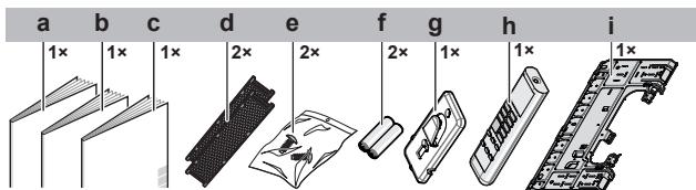
a Installation manual
b Operation manual
c General safety precautions
d Titanium apatite deodorizing and silver particle filter (only for FTXP)
e Indoor unit fixing screw (M4×12L). Refer to "5.5.3 To fix the unit on the mounting plate" on page 10.
f Dry battery AAA.LR03 (alkaline) for user interface
g User interface holder
h User interface
i Mounting plate
3 About the unit

WARNING: FLAMMABLE MATERIAL
The refrigerant inside this unit is mildly flammable.
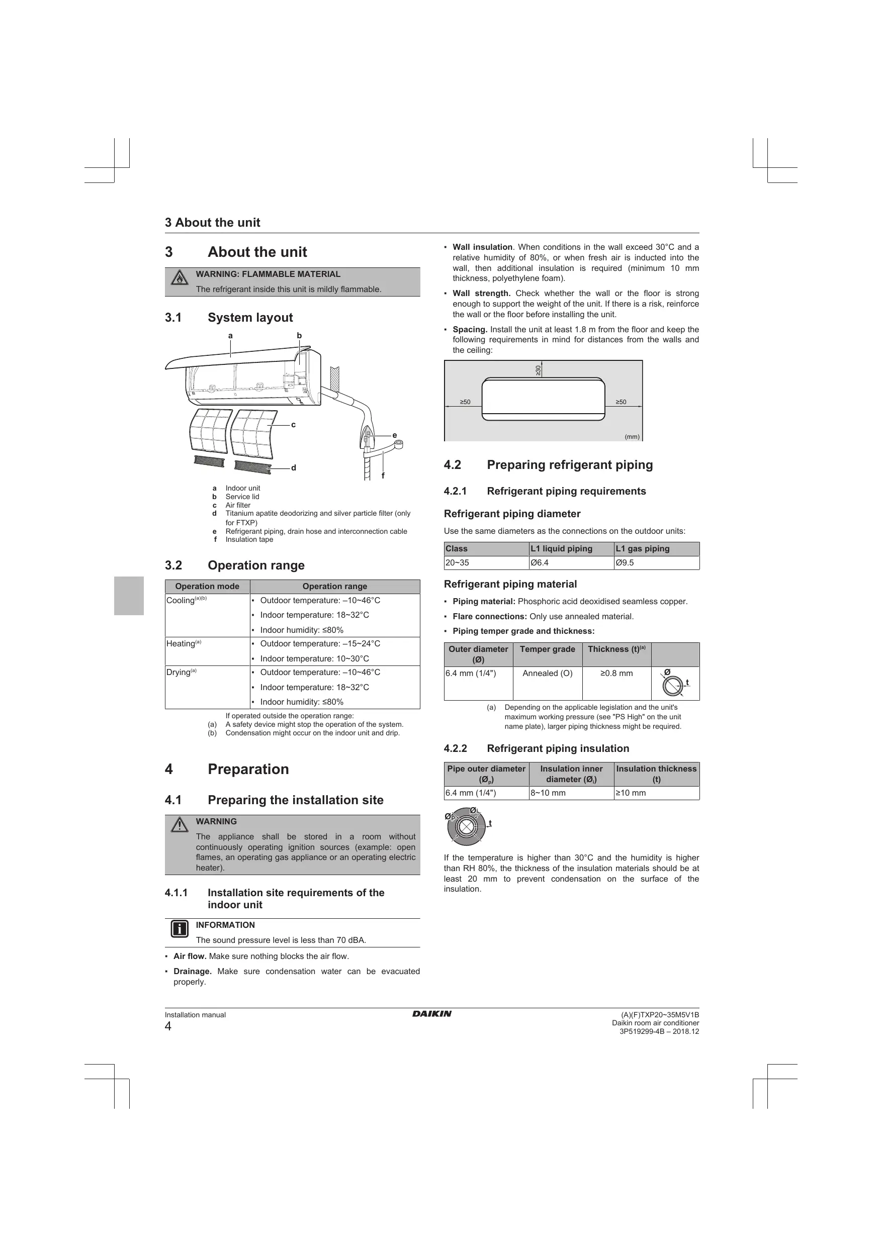
3.1 System layout
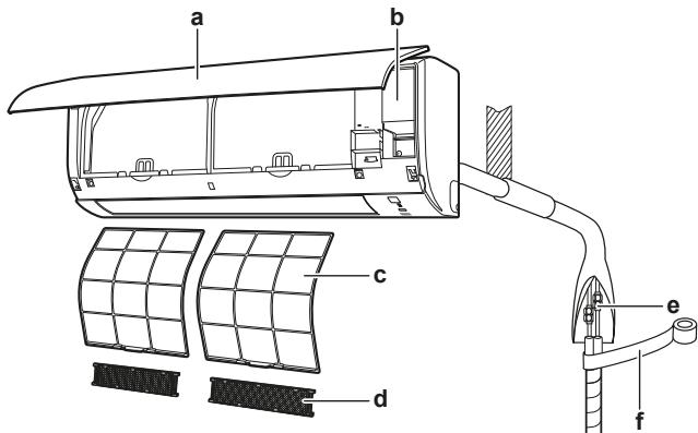
a Indoor unit
b Service lid
c Air filter
d Titanium apatite deodorizing and silver particle filter (only for FTXP)
e Refrigerant piping, drain hose and interconnection cable
f Insulation tape
3.2 Operation range
| Operation mode | Operation range |
| Cooling(a)(b) | ·Outdoor temperature: -10~46°C ·Indoor temperature: 18~32°C ·Indoor humidity: ≤80% |
| Heating(a) | ·Outdoor temperature: -15~24°C ·Indoor temperature: 10~30°C |
| Drying(a) | ·Outdoor temperature: -10~46°C ·Indoor temperature: 18~32°C ·Indoor humidity: ≤80% |
If operated outside the operation range:
(a) A safety device might stop the operation of the system.
(b) Condensation might occur on the indoor unit and drip.
4 Preparation
4.1 Preparing the installation site

WARNING
The appliance shall be stored in a room without continuously operating ignition sources (example: open flames, an operating gas appliance or an operating electric heater).
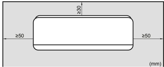
4.1.1 Installation site requirements of the indoor unit

INFORMATION
The sound pressure level is less than 70 dBA.
Air flow. Make sure nothing blocks the air flow.
- Drainage. Make sure condensation water can be evacuated properly.
- Wall insulation. When conditions in the wall exceed 30^ and a relative humidity of 80% , or when fresh air is inducted into the wall, then additional insulation is required (minimum 10 mm thickness, polyethylene foam).
- Wall strength. Check whether the wall or the floor is strong enough to support the weight of the unit. If there is a risk, reinforce the wall or the floor before installing the unit.
- Spacing. Install the unit at least 1.8m from the floor and keep the following requirements in mind for distances from the walls and the ceiling:
4.2 Preparing refrigerant piping
4.2.1 Refrigerant piping requirements
Refrigerant piping diameter
Use the same diameters as the connections on the outdoor units:
| Class | L1 liquid piping | L1 gas piping |
| 20~35 | Ø6.4 | Ø9.5 |
Refrigerant piping material
- Piping material: Phosphoric acid deoxidised seamless copper.
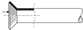
Flare connections: Only use annealed material. - Piping temper grade and thickness:
| Outer diameter (Ø) | Temper grade | Thickness (t)(a) | |
| 6.4 mm (1/4") | Annealed (O) | ≥0.8 mm | Ø t |
(a) Depending on the applicable legislation and the unit's maximum working pressure (see "PS High" on the unit name plate), larger piping thickness might be required.
4.2.2 Refrigerant piping insulation
| Pipe outer diameter (Øp) | Insulation inner diameter (Øi) | Insulation thickness (t) |
| 6.4 mm (1/4") | 8~10 mm | ≥10 mm |
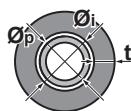
If the temperature is higher than 30^ and the humidity is higher than RH 80% , the thickness of the insulation materials should be at least 20~mm to prevent condensation on the surface of the insulation.
5 Installation
5.1 Opening the indoor unit
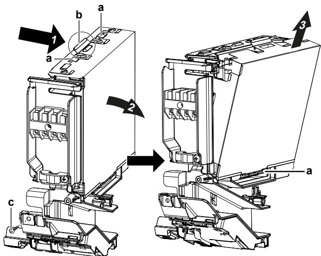
5.1.1 To remove the front panel
1 Hold the front panel by the panel tabs on both sides and open it.
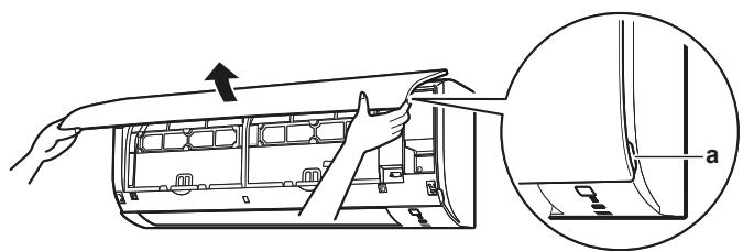
a Panel tabs
2 Remove the front panel by sliding it to the left or the right and pulling it toward you.
Result: The front panel shaft on 1 side will be disconnected.
3 Disconnect the front panel shaft on the other side in the same manner.
a Front panel shaft
5.1.2 To re-install the front panel
1 Attach the front panel. Align the shafts with the slots and push them all the way in.
2 Close the front panel slowly; press at both sides and at the centre.
5.1.3 To remove the front grille

CAUTION
Wear adequate personal protective equipment (protective gloves, safety glasses,...) when installing, maintaining or servicing the system.
1 Remove the front panel to remove the air filter.
2 Remove 2 screws from the front grille.
3 Push down the 3 upper hooks marked with a symbol with 3 circles.
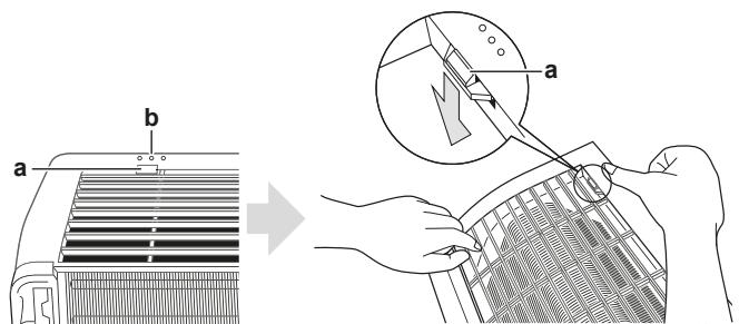
a Upper hook
b Symbol with 3 circles
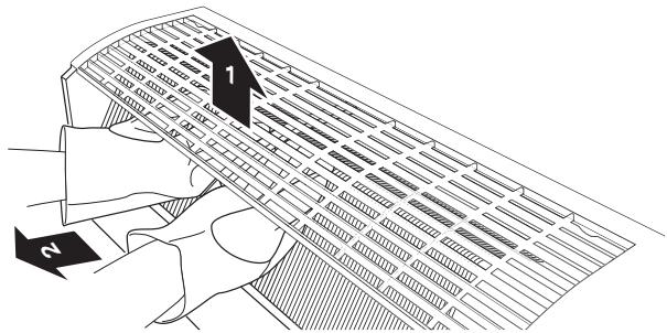
4 We recommend opening the flap before removing the front grille.
5 Place both hands under the centre of the front grille, push it up and then toward you.
5.1.4 To re-install the front grille
1 Install the front grille and firmly engage the 3 upper hooks.
2 Install 2 screws (class 20 35 ) back on the front grille.
3 Install the air filter and then mount the front panel.
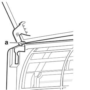
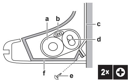
5.1.5 To remove the electrical wiring box cover
1 Remove the front grille.
2 Remove 1 screw from the electrical wiring box.
3 Open the electrical wiring box cover by pulling the protruding part on the top of the cover.
4 Unhook the tab on the bottom and remove the electrical wiring box cover.
a Tab
b Protruding part on the top of the cover
c Screw
5 To re-install the cover, first hook the bottom tab onto the electrical wiring box, and slide the cover into the 2 upper tabs.
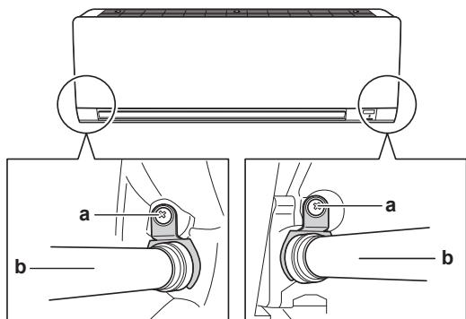
5.1.6 To open the service cover
1 Remove 1 screw from the service cover.
2 Pull out the service cover horizontally away from the unit.
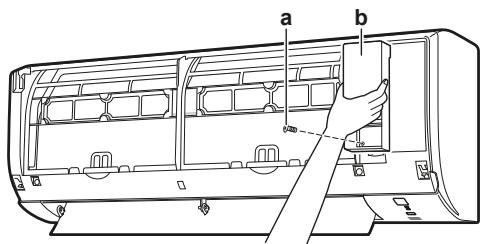
a Service cover screw
b Service cover
5.2 Installing the indoor unit
5.2.1 To install the mounting plate
1 Install the mounting plate temporarily.
2 Level the mounting plate.
3 Mark the centres of the drilling points on the wall using a tape measure. Position the end of tape measure at symbol "▶".
4 Finish the installation by securing the mounting plate on the wall using M4×25L screws (field supply).

INFORMATION
The removed pipe port cover can be kept in the mounting plate pocket.
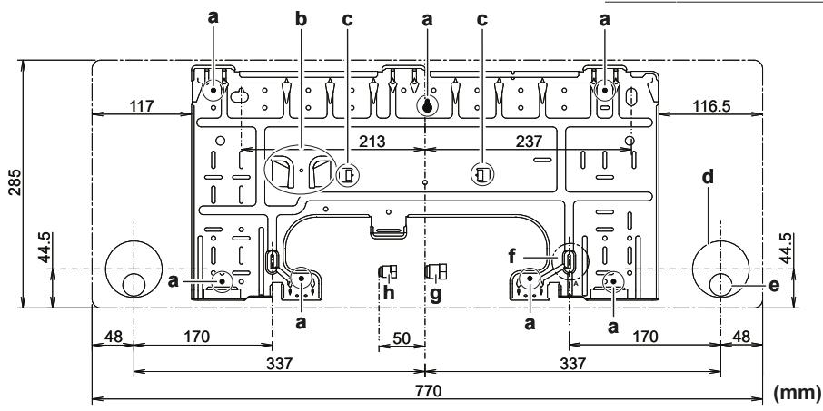
A Class 20~35
a Recommended mounting plate fixing spots
b Pocket for the pipe port cover
c Tabs for placing a spirit level
d Through-the-wall hole 65mm
e Drain hose position
f Position for the tape measure at symbol " > "
Gas pipe end
h Liquid pipe end
5.2.2 To drill a wall hole

CAUTION
For walls containing a metal frame or a metal board, use a wall embedded pipe and wall cover in the feed-through hole to prevent possible heat, electrical shock, or fire.

NOTICE
Be sure to seal the gaps around the pipes with sealing material (field supply), in order to prevent water leakage.
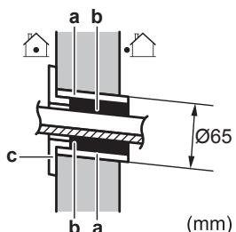
1 Bore a 65 mm large feed-through hole in the wall with a downward slope towards the outside.
2 Insert a wall embedded pipe into the hole.
3 Insert a wall cover into the wall pipe.
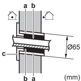
(mm)
a Wall embedded pipe
b Putty
c Wall hole cover
4 After completing wiring, refrigerant piping and drain piping, do NOT forget to seal the gap with putty.
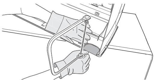
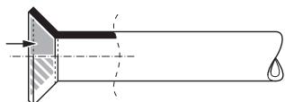
5.2.3 To remove the pipe port cover
To connect the piping on right-side, right-bottom, left-side or left-bottom, the pipe port cover MUST be removed.
1 Cut off the pipe port cover from inside the front grille using a coping saw.
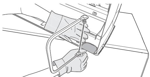
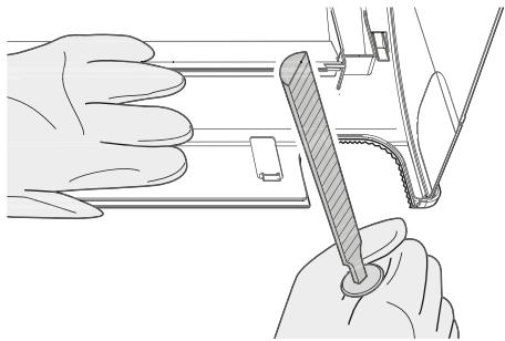
2 Remove any burrs along the cut section using a half round needle file.
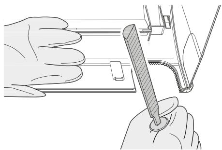

NOTICE
Do NOT use nippers to remove the pipe port cover, as this would damage the front grille.
5.2.4 To provide drainage
Make sure condensation water can be evacuated properly. This involves:
- General guidelines
- Connecting the drain piping to the indoor unit
- Checking for water leaks
General guidelines
- Pipe length. Keep drain piping as short as possible.
- Pipe size. If drain hose extension or embedded drain piping is required, use appropriate parts that match the hose front end.

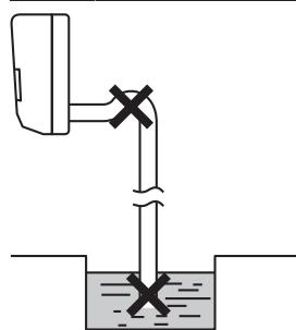
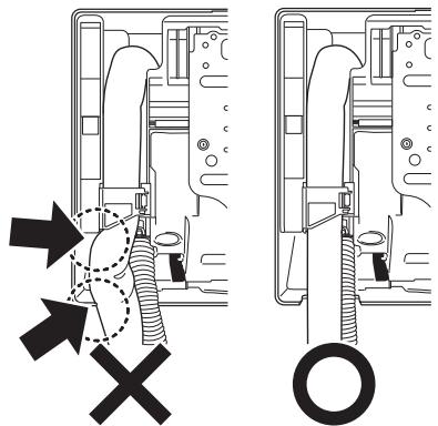
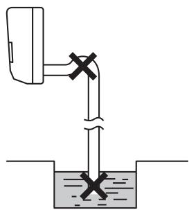
NOTICE
- Install the drain hose with a downward slope.
Traps are NOT permitted. - Do NOT put the end of the hose in water.
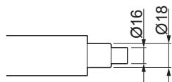
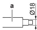
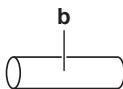
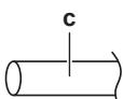
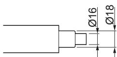
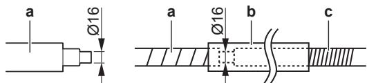
- Drain hose extension. To extend the drain hose, use a field supplied hose with inner 016 ~mm . Do NOT forget to use a heat insulation tube on the indoor section of the extension hose.
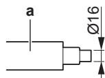
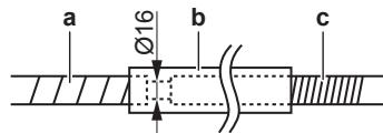
a Drain hose supplied with the indoor unit
b Heat insulation tube (field supply)
c Extension drain hose
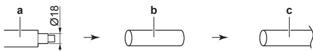
- Rigid polyvinyl chloride pipe. When connecting a rigid polyvinyl chloride pipe (nominal 13mm ) directly to the drain hose as with embedded piping work, use a field supplied drain socket (nominal 13mm ).


a Drain hose supplied with the indoor unit
b Drain socket with nominal 13mm (field supply)
c Rigid polyvinyl chloride pipe (field supply)
- Condensation. Take measures against condensation. Insulate the complete drain piping in the building.
1 Insert the drain hose in the drain pipe as shown in the following figure, so it will NOT be pulled out of the drain pipe.
To connect the piping on right side, right-back, or right-bottom

INFORMATION
The factory default is right-side piping. For left-side piping, remove the piping from the right side and install it on the left side.
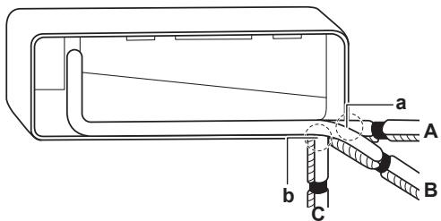
1 Attach the drain hose with adhesive vinyl tape to the bottom of the refrigerant pipes.
2 Wrap the drain hose and the refrigerant pipes together using insulation tape.
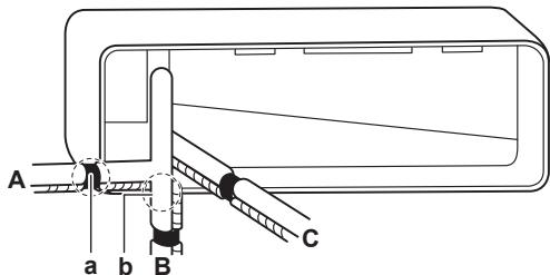
A Right-side piping
B Right-bottom piping
C Right-back piping
a Remove the pipe port cover here for right-side piping.
b Remove the pipe port cover here for right-bottom piping.
To connect the piping on left side, left-back, or left-bottom

INFORMATION
The factory default is right-side piping. For left-side piping, remove the piping from the right side and install it on the left side.
1 Remove the insulation fixing screw on the right side and remove the drain hose.
2 Remove the drain plug on the left side and attach it to the right side.

NOTICE
Do NOT apply lubricating oil (refrigerant oil) to the drain plug when inserting it. The drain plug may deteriorate and cause drain leakage from the plug.
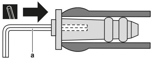
a 4 mm hexagonal wrench
3 Insert the drain hose on the left side and do not forget to tighten it with the fixing screw; otherwise water leakage may occur.
a Insulation fixing screw
b Drain hose
4 Attach the drain hose to the refrigerant pipes bottom side using adhesive vinyl tape.
A Left-side piping
B Left-back piping
C Left-bottom piping
a Remove the pipe port cover here for left-side piping.
b Remove the pipe port cover here for left-bottom piping.
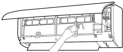
To check for water leaks
1 Remove the air filters.
2 Gradually pour approximately 1 l of water in the drain pan, and check for water leaks.
5.3 Connecting the refrigerant piping

DANGER: RISK OF BURNING
5.3.1 Guidelines when connecting the refrigerant piping
Take the following guidelines into account when connecting pipes:
- Coat the flare inner surface with ether oil or ester oil when connecting a flare nut. Tighten 3 or 4 turns by hand, before tightening firmly.
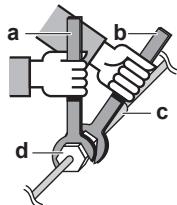
- ALWAYS use 2 wrenches together when loosening a flare nut.
- ALWAYS use a spanner and torque wrench together to tighten the flare nut when connecting the piping. This to prevent nut cracking and leaks.
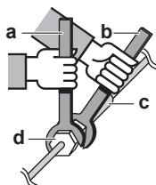
a Torque wrench
b Spanner
C Piping union
d Flare nut
| Piping size (mm) | Tightening torque (N·m) | Flare dimensions (A) (mm) | Flare shape (mm) |
| Ø6.4 | 15~17 | 8.7~9.1 | 90±2 45° R=0.4~0.8 |
| Ø9.5 | 33~39 | 12.8~13.2 | |
| Ø12.7 | 50~60 | 16.2~16.6 |
5.3.2 To connect the refrigerant piping to the indoor unit
- Pipe length. Keep refrigerant piping as short as possible.
- Flare connections. Connect refrigerant piping to the unit using flare connections.
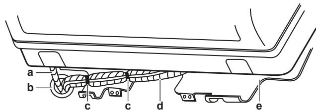
- Insulation. Insulate the refrigerant piping, interconnection cable and drain hose on the indoor unit as follows:
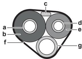
a Gas pipe
Gas pipe insulation
c Interconnection cable
d Liquid pipe
Liquid pipe insulation
f Finishing tape
g Drain hose

NOTICE
Make sure to insulate all refrigerant piping. Any exposed piping might cause condensation.
5.4 Connecting the electrical wiring

DANGER: RISK OF ELECTROCUTION

WARNING
ALWAYS use multicore cable for power supply cables.

WARNING
If the supply cord is damaged, it MUST be replaced by the manufacturer, its service agent or similarly qualified persons in order to avoid a hazard.

WARNING
Do NOT connect the power supply to the indoor unit. This could result in electrical shock or fire.

WARNING
- Do NOT use locally purchased electrical parts inside the product.
- Do NOT branch the power supply for the drain pump, etc. from the terminal block. This could result in electrical shock or fire.

WARNING
Keep the interconnection wiring away from copper pipes without thermal insulation as such pipes will be very hot.
5.4.1 To connect the electrical wiring on the indoor unit
Electrical work should be carried out in accordance with the installation manual and the national electrical wiring rules or code of practice.
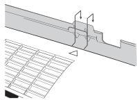
1 Set the indoor unit on the mounting plate hooks. Use the "△" marks as a guide.
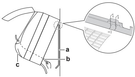
a Mounting plate (accessory)
b Interconnection cable
c Wire guide
2 Open the front panel, and then the service cover. Refer to "5.1 Opening the indoor unit" on page 5.
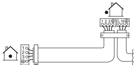
3 Pass the interconnection cable from the outdoor unit through the feed-through wall hole, through the back of the indoor unit and through the front side.
Note: In case the interconnection cable was stripped in advance, cover the ends with insulating tape.
4 Bend the end of the cable up.

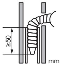
NOTICE
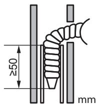
- Be sure to keep the power line and transmission line apart from each other. Transmission wiring and power supply wiring may cross, but may NOT run parallel.
- In order to avoid any electrical interference the distance between both wires should ALWAYS be at least 50~mm .

WARNING
Provide adequate measures to prevent that the unit can be used as a shelter by small animals. Small animals that make contact with electrical parts can cause malfunctions, smoke or fire.
5 Strip the wire ends approximately 15mm
6 Match wire colours with terminal numbers on the indoor unit terminal blocks and firmly screw the wires to the corresponding terminals.
7 Connect the earth wire to the corresponding terminal.
8 Firmly fix the wires with the terminal screws.
9 Pull the wires to make sure that they are securely attached, then retain the wires with the wire retainer.
10 Shape the wires so that the service cover fits securely, then close the service cover.
5.5 Finishing the indoor unit installation
5.5.1 To insulate the drain piping, refrigerant piping and interconnection cable
1 After the drain piping, refrigerant piping and the electrical wiring are finished. Wrap refrigerant pipes, interconnection cable and drain hose together using insulation tape. Overlap at least half the width of the tape with each turn.
a Drain hose
b Interconnection cable
c Mounting plate (accessory)
d Refrigerant pipes
e Indoor unit fixing screw M4×12L (accessory)
f Bottom frame
5.5.2 To pass the pipes through the wall hole
1 Shape the refrigerant pipes along the pipe path marking on the mounting plate.
a Drain hose
b Caulk this hole with putty or caulking material.
c Adhesive vinyl tape
d Insulation tape
e Mounting plate (accessory)

NOTICE
- Do NOT bend refrigerant pipes.
- Do NOT push the refrigerant pipes onto the bottom frame or the front grille.
2 Pass the drain hose and refrigerant pipes through the wall hole.
5.5.3 To fix the unit on the mounting plate
1 Set the indoor unit on the mounting plate hooks. Use the "△" marks as a guide.
2 Press the bottom frame of the unit with both hands to set it on the bottom hooks of the mounting plate. Make sure that the wires do NOT get squeezed anywhere.
Note: Take care that the interconnection cable does NOT get caught in the indoor unit.
3 Press the bottom edge of the indoor unit with both hands until it is firmly caught by the mounting plate hooks.
4 Secure the indoor unit to the mounting plate using 2 indoor unit fixing screws M4×12L (accessory).
6 Configuration
6.1 To set a different address
In case 2 indoor units are installed in 1 room, different addresses for 2 user interfaces can be set.
1 Remove the batteries from the user interface.
2 Cut the address jumper.
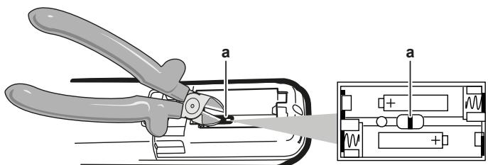
a Address jumper

NOTICE
Be careful NOT to damage any of the surrounding parts when cutting the address jumper.
3 Turn the power supply on.
Result: The flap of the indoor unit will open and close to set the reference position.

INFORMATION
- For FTXF units, the following setting MUST be completed within 5 minutes after the power supply is turned on.
- In case you could NOT complete the setting in time, turn the power supply off and wait at least 1 minute before turning the power supply back on.
4 Press simultaneously:
| Model | Buttons |
| FTXP and ATXP | ^TEMP, ^TEMP and OFF |
| FTXF | MODE, ^TEMP and ^TEMP |
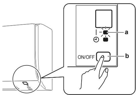
5 Press:
| Model | Button |
| FTXP and ATXP | ^TEMP |
| Model | Button |
| FTXF | MODE |
6 Select:
| Model | Symbol |
| FTXP and ATXP | R |
| FTXF | ?~ |
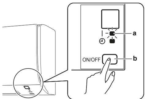
7 Press:
| Model | Button |
| FTXP and ATXP | FAN |
| FTXF |
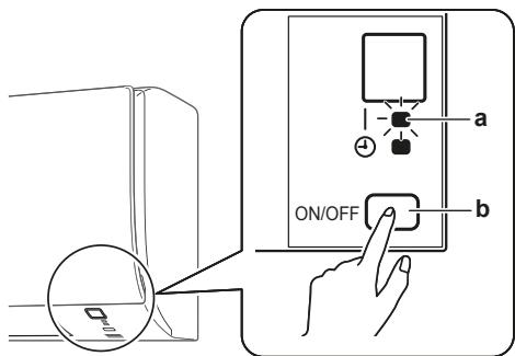
a Operation lamp
b Indoor unit ON/OFF switch
8 Press the indoor unit ON/OFF switch while the operation lamp is blinking.
| Jumper | Address |
| Factory setting | 1 |
| After cutting with nippers | 2 |

INFORMATION
If the setting could NOT be completed while the operation lamp was blinking, repeat the setting process from the beginning.
9 When the setting is complete, press:
| Model | Button |
| FTXP and ATXP | Keep FAN pressed for about 5 seconds. |
| FTXF |
Result: The user interface will return to the previous screen.
10 Press simultaneously:
| Model | Buttons |
| FTXP | ^TEMP, ^TEMP and OFF |
| FTXF | MODE, ^TEMP and ^TEMP |
11 Press:
| Model | Button |
| FTXP | ^TEMP |
| FTXF | MODE |
12 Select:
| Model | Symbol |
| FTXP | R |
| FTXF | ?° |
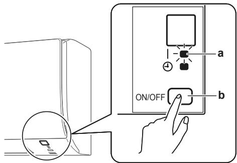
13 Press:
| Model | Button |
| FTXP | FAN |
| FTXF |
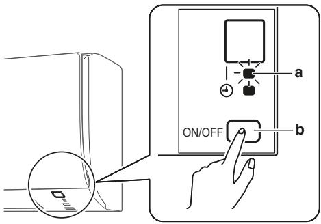
a Operation lamp
b Indoor unit ON/OFF switch
14 Press the indoor unit ON/OFF switch while the operation lamp is blinking.
| Jumper | Address |
| Factory setting | 1 |
| After cutting with nippers | 2 |

INFORMATION
If the setting could NOT be completed while the operation lamp was blinking, repeat the setting process from the beginning.
15 When the setting is complete, press:
| Model | Button |
| FTXP | Keep FAN pressed for about 5 seconds. |
| FTXF |
Result: The user interface will return to the previous screen.
7 Commissioning

NOTICE
NEVER operate the unit without thermistors and/or pressure sensors/switches. Burning of the compressor might result.
7.1 Checklist before commissioning
Do NOT operate the system before the following checks are OK:
| □ | You read the complete installation instructions, as described in the installer reference guide. |
| □ | The indoor units are properly mounted. |
| □ | The outdoor unit is properly mounted. |
| □ | Air inlet/outlet Check that the air inlet and outlet of the unit is NOT obstructed by paper sheets, cardboard, or any other material. |
| □ | There are NO missing phases or reversed phases. |
| □ | The refrigerant pipes (gas and liquid) are thermally insulated. |
| □ | Drainage Make sure drainage flows smoothly. Possible consequence: Condensate water might drip. |
| □ | The system is properly earthed and the earth terminals are tightened. |
| □ | The fuses or locally installed protection devices are installed according to this document, and have NOT been bypassed. |
| □ | The power supply voltage matches the voltage on the identification label of the unit. |
| □ | The specified wires are used for the interconnection cable. |
| □ | The indoor unit receives the signals of the user interface. |
| □ | There are NO loose connections or damaged electrical components in the switch box. |
| □ | The insulation resistance of the compressor is OK. |
| □ | There are NO damaged components or squeezed pipes on the inside of the indoor and outdoor units. |
| □ | There are NO refrigerant leaks. |
| □ | The correct pipe size is installed and the pipes are properly insulated. |
| □ | The stop valves (gas and liquid) on the outdoor unit are fully open. |
7.2 To perform a test run
Prerequisite: Power supply MUST be in the specified range.
Prerequisite: Test run may be performed in cooling or heating mode.
Prerequisite: Test run should be performed in accordance with the operation manual of the indoor unit to make sure that all functions and parts are working properly.
1 In cooling mode, select the lowest programmable temperature. In heating mode, select the highest programmable temperature. Test run can be disabled if necessary.
2 When the test run is finished, set the temperature to a normal level. In cooling mode: 26 28^ , in heating mode: 20 24^ .
3 The system stops operating 3 minutes after the unit is turned OFF.
7.2.1 To perform a test run in winter season
When operating the air conditioner in Cooling mode in winter, set it to test run operation using the following method.
For FTXP units
1 Press TEMP , , and OFF simultaneously.
2 Press TEMP
3 Select 7.
4 Press FAN
5 Press COOL to switch the system on.
Result: Test run operation will stop automatically after about 30 minutes.
6 To stop operation, press OFF.
For FTXF units
7 Press to switch the system on.
8 Press the centre of , and MODE simultaneously.
9 Press MODE twice.
Result: 7^ will appear on the display. Test run operation is selected. Test run operation will stop automatically after about 30 minutes.
10 To stop operation, press.

INFORMATION
Some of the functions CANNOT be used in the test run operation mode.
If a power failure occurs during operation, the system automatically restarts immediately after power is restored.
8 Disposal
Dismantling of the unit and treatment of the refrigerant, oil and other parts MUST comply with the applicable legislation.
9 Technical data
A subset of the latest technical data is available on the regional Daikin website (publicly accessible). The full set of latest technical data is available on the Daikin Business Portal (authentication required).
9.1 Wiring diagram
| Unified Wiring Diagram Legend | |||||
| For applied parts and numbering, refer to the wiring diagram on the unit. Part numbering is by Arabic numbers in ascending order for each part and is represented in the overview below by symbol “*” in the part code. | |||||
| CIRCUIT BREAKER | PROTECTIVE EARTH | ||||
| CONNECTION | PROTECTIVE EARTH (SCREW) | ||||
| CONNECTOR | RECTIFIER | ||||
| EARTH | RELAY CONNECTOR | ||||
| FIELD WIRING | SHORT-CIRCUIT CONNECTOR | ||||
| FUSE | TERMINAL | ||||
| INDOOR UNIT | TERMINAL STRIP | ||||
| OUTDOOR UNIT | WIRE CLAMP | ||||
| BLK: BLACK | GRN: GREEN | PNK: PINK | WHT: WHITE | ||
| BLU: BLUE | GRY: GREY | PRP, PPL: PURPLE | YLW: YELLOW | ||
| BRN: BROWN | ORG: ORANGE | RED: RED | |||
| PRINTED CIRCUIT BOARD | PS: SWITCHING POWER SUPPLY | ||||
| PUSHBUTTON ON/OFF, OPERATION SWITCH | PTC: THERMISTOR PTC | ||||
| BUZZER | Q: INSULATED GATE BIPOLAR TRANSistor (IGBT) | ||||
| CAPACITOR | |||||
| CONNECTION, CONNECTOR | Q*DI: EARTH LEAK CIRCUIT BREAKER | ||||
| Q*L: OVERLOAD PROTECTOR | |||||
| Q*M: THERMO SWITCH | |||||
| DIODE: R*: RESISTOR | |||||
| DIODE BRIDGE: THERMISTOR | |||||
| DIP SWITCH: RECEIVER | |||||
| HEATER: LIMIT SWITCH | |||||
| FUSE: FLOAT SWITCH | |||||
| S*NPH: PRESSURE SENSOR (HIGH) | |||||
| S*NPL: PRESSURE SENSOR (LOW) | |||||
| S*PH, HPS*: PRESSURE SWITCH (HIGH) | |||||
| S*PL: PRESSURE SWITCH (LOW) | |||||
| S*T: THERMOSTAT | |||||
| S*RH: HUMIDITY SENSOR | |||||
| S*W, SW*:OPERATION SWITCH | |||||
| S*A*, F1S: SURGE ARRESTOR | |||||
| SR*, WLU: SIGNAL RECEIVER | |||||
| SS*: SELECTOR SWITCH | |||||
| COIL: SHEET METAL: TERMINAL STRIP FIXED PLATE | |||||
| REACTOR: T*TRANSFORMER | |||||
| STEPPER MOTOR: TRANSMITTER | |||||
| COMPRESSOR MOTOR: VARISTOR | |||||
| FAN MOTOR: DIODE BRIDGE | |||||
| DRAIN PUMP MOTOR: WIRELESS REMOTE CONTROLLER | |||||
| SWING MOTOR: TERMINAL | |||||
| MAGNETIC RELAY: TERMINAL STRIP (BLOCK) | |||||
| NEUTRAL: ELECTRONIC EXPANSION VALVE COIL | |||||
| NUMBER OF PASSES THROUGH FERRITE CORE: REVERSING SOLENOID VALVE COIL | |||||
| PAM: PULSE-AMPLITUDE MODULATION: FERRITE CORE | |||||
| PCB*: PRINTED CIRCUIT BOARD: NOISE FILTER | |||||
| PM*: POWER MODULE: | |||||
Inhaltsverzeichnis
GEFAHR: STROMSCHLAGGEFAHR

WARNING
| Modell | Symbol |
| FTXP | R |
| FTXF | ?° |
13 Drucken:
| Modell | Taste |
| FTXP | FAN |
| FTXF |
WAARSCHUWING:ONTVLAMBAAR MATERIAL
| Model | Symbol |
| FTXP | R |
| FTXF | ?~ |
13 Druk:
| Model | Knop |
| FTXP | FAN |
| FTXF |
a Bedrijslampje
b ON/OFF-schakelaar binnenunit
1.1 PII npopopiecs yia to npov Eyypapo 69
2 PIInpoopiecs yia tn ouokeuocia 69
2.1 EoWtepikn povda 70
2.1.1 Ia va aapaieoTe Ta eapntmuata aTou Tnv eoWtepkn ova 70
5.2 MoHTax BByTpEHHero 6noka 95
5.2.1 YCTAHOBKA MOHTAXHONIJIACTINbI 95
5.2.2 UTo6bl npocBepnItb OTBepCTne B CTeHe 95
5.2.3 ChTb KpbuKy OTBepctna noT prboPBOoD... 96
5.2.4 OobctpoiCtvoDpehaxka 96
5.3 CoeINHeHne Tpyb TpyboPoBOda XnaDaareHTa 97
5.3.1 Yka3aHnI NO pOcEiHEnHIO Tpy6oPbOBoDOB xlaDaIeHTA 97
5.3.2 CoeDInHeHne Tpy6oPbOBoVa xnaIaReHtAc BHyTpEHHM arperaTOM 98
5.4 PoiokJIoueHne 3JIeKTPoPnPoBOKn 98
5.4.1 Пдкночене злесгрповдк вутpenHeMy 6noky 98
5.5 3abepseHne MOHTaKa BHyTppeHrero arperata 99
5.5.1 706bI 3aI3OIIPOBaT bIpeHaXHbIe Tpy6bl, Tpy6oPiPoBOd XlaJaIaReHTa I CoeINHITeJIbHbI Ka6eBb 99
5.5.2 чтобы пponуспь Трубы чере оТоверсте в стени. 99
5.5.3 YTO6bI 3aФИКСИРОВаТь 6ЛOK Ha MOHTAXHNo ПпаCTинe 99
6 KondupynpoBaHne 99
6.1 HacrpoKa dpynix aDpecoB 99
7 NyckoHaJaKa 101
7.1 PnpdyckobIe npOBepOHyIe onepaun 101
7.2 Iopraok BbIOpHHeHn Ipo6Horo 3ayncKa 101
7.2.1 Ipo6hBiy 3aynck 3moi 101
8 ytni3aun 101
9 TexHHueckne daHHbIe 102
9.1 Cxema 3JIeKTrpOnpoBODKn 102
1 IHHOpMaunO dOKymeHTaun
1.1 Информацьу O Habстаям дOKумente

INHOPMALIJA
1 POMeCTHTeJIiueBvU pAnHeIbHaMeCTo.COBMeCTNB CTePxHnC THe3dAMN, BCTaBbTe INX TuJa DO yNopa.
2 He TopoJcB, 3akpoIte IInueByIO nAHeJIb, HaxImaHa Hee no 6okam nOcepeDInHe.
2 BCTaBbTe BOTBepCTne 3aIeJIbIbAemyBOCTehy Tpy6y.
3 BCTaBbTe B Tpy6y HAcTeHHyIO KpbilIky.
a 3aIeJIbIbAeMaB BCTeHy TpyBa
b ⅢnataBka
c 3arJyka OTBepCTnB CTeHe
4 Ito OKOHaHnnpokJaKn Tpy6OpPObOa XlaaReHtA, npoBODK n CInBHO Tpy6OpPObOa O8r3ATEJIbHO 3anoJHnTe 3a3op UNaTJeBkoI.
5.2.3 UTo6bI ChrTb KpbIuKy OTBepCTnI IOd Tpy6oNpOBoD
YtobIpoCoeHnHTpbyoPoBOc npaba, cnpaba Cn3y, cneBa nnCbeBa Cn3y, HEOBXOIMO ChrBkpykky OTbepctna noD TpyoBoPOB.
1 Cpekte IIO63nKOM KpbIuKU OTBepCTNIO Tpy6oPBOOc BHyTpeHHe CTOpOnbI nepeDHe peWetKn.
2 Y6epnte co cpe3a 3ayceHbI NOJyKpyTbIM HAnJIbHnKOM.

ПОНМЕЧАНЕ
Bo n36exahanne nobpejxdenna nepedne peweTkn HE noIb3yItecb Kycaukamn, ChIMaKpbIuKy C OTBepCTnno Tpy6oPBOvO.
5.2.4 O6ycTpoIcTBo IpeHaxa
Посселпerte 3a CBOбныIM OTBODOM BOДЯНО KOндЕнсаТ. ДяЗТOrO Heo6xOДИМО:
- 06ecneuNb c6bIouHe nue o6ux npaBn
-ПодсоeДинHTb cINBHOТуБОпpoВOD K BHyTpEHHeMy 6IOKy - Поверпь, Нет Лп потук.
O6uIe npaBnla
-Динагубогроба.CЛИВно Trpyбогровд ДОЛжен 6ыткak можно корочe.
Pa3mep Tpy6ok. Ecnn Tpe6yeTc ydInHeHne dpehaxHoRo 7laHra nn 3aJeIka dpehaxHbIX Tpy6, nCnObl3yIte DeTaII, COOTBETCTByUOuNe nepeHEmy KOHcy 7laHra.

ПОНМЕЧАНЕ
CINBHOI JIaHn POKJIaDbIbAeTcYKJIOHOM BHN3.
Ловушик HEdonyckaHOTcA.
HE onyckaia Te KOHeu 7JHaRa B BoVy.
- YdHHeHcCnBHOO ShaHa. YdHnHTb CnBHOJ MoXHO C NMOUbHO UHaHra 016 MM, KOtOpbI pNObpeTaETcNo MeCTy MOHTaxa obOpuDobAHna. HE 3a6yDbTe NOMeCTNb B TepMOH3OJIpyUOuTy Otp6Ky OTpe3OK HapaueHHoro UHaHa, IPOLOKeHHbI B NOMeUeHN.
a CnBHOJ WLaHr, BXOJaIIN B KOMPJIeKTAuIIO BHyTpEHHero 6noka
b Tepmon30JnpyuOaT py6ka (npno6peTaetcno Mecty yCTaHOBKn)
c YdInHHTeJIb CnBHOro WnHaHra
- Tpy6ka n3 JecTKORO noINBHHNIXNOPnJa. EcIn Tpy6ka n3 JecTKORO noINBHHNIXNOPnJa (HOMHNOM 013 MM) NOCDoeHNHaeTc HAnpMyo K CInBHOmy JIaHry KaK Tpy6ka dJy 3aJeIKN, INCNoJIb3ayTe CInBHO nATpy6ok (HOMHNOM 013 MM), KOtOpBn Iprno6peTaETc No MeCy UCTaHOBKn.
a CnBHOJ WLaHr, BXOJaIeN B KOMPJIeKtaIu BHyTpEHHero 6noka
b CnBHOI nATpy6OK HOMHHaON M 13 MM (npno6peTaetcno MeCTy yCTaHOBKn)
c Tpyka n3 kectkoro noINBHHnIxnpnda (npno6peTaetcno MeCTy yCTaHOBKn)
- KoHdEhcaun. IpnMITE MepbI BO n36eJahne o6pa3oBaHnI KOHdEHCata. BeCb cINBHO Tpy6OpBoD B 3aHmN Heo6xOJMo 3aH3OJnPoBaTb.
1 BCTaBbTe CnIBHOI UHaB H B CnIBHyIO Tpy6ky, KaK noka3aHO Ha pucyHke HIXKe, CneJa 3a TeM, YTO6bI UHaHr HEJIb3R 6blIO 6bl BBITAYHb N3 CnIBHOI Tpy6Kn.
5.3 CoeINHeHne Tpy6 Tpy6OpPObOda xlaIaIaReHTa

ONACHO! PNUCK OXKOROB
5.3.1 Yka3aHnI NO NOdCoeINHeHnIO Tpy6oNpOBoIDOB XJaDaReHTA
Pn noDcoeHHeHn Tpyb Heo6xOaMo co6JIouaTb cNeyuOuine npabuna:
- Пи 3атяжke Накдноу raikn Hahecnte Ha BHytpehHIO NOBepxHOCTb pa3BaJIbIcOBAHNO qactn Tpy6bl 3ФИрhoe nIN NOIIaФИрhoe macNo. PpncTypan K 3aTЯжke HaNДHOr RaIKN, HAKINBEte ee, cdeIab 3 - 4 obopota pykoJ.
- Ocna6nra NaKuHbIe raiKu, O5a3ATEJIbHO noIb3yItecB cpa3y DByMRAeUHbIMN KIIIOUAMN.
- Пи-coeHHeHn try6 ДЯЗЯЖн haKInDbIx raeK BCErДA ПОЛьЗИТecь OДНOBpeMeHHO obiHbIM raeHbIM I ДИнHamOMeTpIYeCEkM KlnOуAMN. 3TO IpeIoTbPaTIT NOBpeXdHne raEK I BO3HnKHOBeHne yTeueK.
a DnHAMOMETPnueeCKN KlnOu
b TaeuHbI KInOy
c CoeINHeHne Tpy6
d HakuHna raKa
| Model | Dügmeler |
| FTXP ve ATXP | TEMP, TEMP, ve OFF |
| FTXF | MODE, TEMP, ve TEMP |
5 Basin:
| Model | Düğme |
| FTXP ve ATXP | ^TEMP |
| FTXF | MODE |
6 Seçin:
| Model | Sembol |
| FTXP ve ATXP | R |
| FTXF | ?° |
7 Basin:
| Model | Düğme |
| FTXP ve ATXP | FAN |
| FTXF |
a Calisma lambasi
b ic unite ON/OFF anahtari
8 Calisma lambasi yanip sonerken ON/OFF anahtarina basin.
| Model | Dügmeler |
| FTXP | TEMP, TEMP, ve OFF |
| FTXF | MODE, TEMP, ve TEMP |
11 Basin:
| Model | Düğme |
| FTXP | ^TEMP |
| FTXF | MODE |
12 Seçin:
| Model | Sembol |
| FTXP | R |
| FTXF | ?° |
13 Basin:
| Model | Düğme |
| FTXP | FAN |
| FTXF |
a Calisma lambasi
b Ic unite ON/OFF anahtari
14 Calisma lambasi yanip sonerken ON/OFF anahtarina basin.