FTXP 2600W - Multisplit indoor unit DAIKIN - Free user manual and instructions
Find the device manual for free FTXP 2600W DAIKIN in PDF.
| Product type | Multisplit indoor unit |
| Brand | Daikin |
| Model | FTXP 2600W |
| Class | 20~35 |
| Dimensions (H × W × D) | 285 × 770 × 225 mm |
| Net weight | 10 kg |
| Power supply | 230 V single-phase, 50 Hz |
| Refrigerant | R32 (mildly flammable) |
| Operating modes | Cooling, heating, dehumidification, ventilation |
| Outdoor temperature range | Cooling: -10°C to 46°C; Heating: -15°C to 24°C |
| Indoor temperature range | Cooling: 18°C to 32°C; Heating: 10°C to 30°C |
| Maximum indoor humidity | 80% RH |
| Included filters | Air filter, titanium apatite deodorizing filter, silver particle filter |
| Noise level | Less than 70 dBA |
| Minimum installation height | 1.8 m from floor |
| Refrigerant pipe diameter | Liquid: Ø6.4 mm; Gas: Ø9.5 mm |
| Wall penetration hole diameter | 65 mm |
| Special functions | Adjustable louvers, winter test mode, automatic restart |
| Filter cleaning | Every 2 weeks (recommended) |
| Included accessories | Remote control, support, batteries, mounting plate, filters |
| Protection rating | IPX0 (indoor use) |
Frequently Asked Questions - FTXP 2600W DAIKIN
User questions about FTXP 2600W DAIKIN
0 question about this device. Answer the ones you know or ask your own.
Ask a new question about this device
Download the instructions for your Multisplit indoor unit in PDF format for free! Find your manual FTXP 2600W - DAIKIN and take your electronic device back in hand. On this page are published all the documents necessary for the use of your device. FTXP 2600W by DAIKIN.
USER MANUAL FTXP 2600W DAIKIN
Daikin room air conditioner
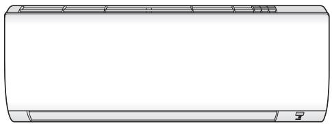
natural_image
Front view line drawing of a single air conditioner unit (no text or symbols)Installation manual
Daikin room air conditioner
FTXP20M5V1B, FTXP25M5V1B, FTXP35M5V1B, ATXP20M5V1B, ATXP25M5V1B, ATXP35M5V1B,
| 01 | are in conformity with the following standard(s) or other normative document(s), provided that these are used in accordance with our instructions: | 08 | estão em conformidade com a(s) seguinte(s) norma(s) ou outro(s) documento(s) normativo(s), desde que estes sejam utilizados de acordo com as nossas instruções: | 16 | megfelelek az alábbi szabvány(ok)nak vagy egyéb irányadó dokumentum(ok)nak, ha azokat előírás szerint használják: | |
| 02 | der/den folgenden Norm(en)/ oder einem anderen Normdokument oder -dokumenten entspricht/entsprechen, unter der Voraussetzung, daß sie gemäß unseren Anweisungen eingesetzt werden: | 09 | coответstуют следующим стандартам или другим нормативным документам, при условии их использования согласно нашим инструкциям: | 17 | spelniają wymogi następujących norm i innych документов normalizacyjnych, pod warunkiem że używane są zgodnie z naszymi instrukçami: | |
| 03 | sont conformes à la/aux norm(s) ou autre(s) document(s) normatif(s), pour autant qu'ils soient utilisés conformément à nos instructions: | 10 | overholder folgende standard(er) eller andet/andre retningsgivende dokument(er), forudsat at disse anvendes i henhold til vore instrukser: | 18 | sunt in conformitate cu umătoralu (umătoarele) standard(e) sau alt(e) document(e) normativ(i), cu condița ca acestea să fie utilizate în conformitate cu instrucțiunie noastre: | |
| 04 | conform de volgende norm(en)/ één de meer andere bindende documenten zijn, op voorwaarde dat ze worden gebruikt overeenkomstig onze instructies: | 11 | respektive utrustning är utford i överensstämmelse med och följer följande standard(er) eller andra normgivande dokument, under förutsättning att användning skeri i överensstämmelse med våra instruktioner: | 19 | skladni z naslednijmi standardi in drugimi normativi, pod pogojem, da se uporabljao v skladu z našimi navodili: | |
| 05 | están en conformidad con la(s) siguiente(s) norma(s) u otro(s) documento(s) normativo(s), siempre que sean utilizados de acuerdo con nuestras instrucciones: | 12 | respektive utstyr er i overensstemmelse med folgende standard(er) eller andre normgivende dokument(er), under forutsetting av at disse brukes i henhold til våre instrukser: | 20 | on vastavuses järgmis(je standardit(je)ga või teiste normativište dokumentidega, kui neid kasutatakse vastavalt meie juhenditele: | |
| 06 | conformi all(i) seguente(i) standard(s) o altro(i) document(i) a carattere normativo, a patto che vengano usati in conformità alle nostre istruzioni: | 13 | vastaavat seuraavien standardien ja muiden ohjeelisten dokumenttien vaatimuksia edellyttäen, että niitä käytetään ohjeidemme mukaisesti: | 21 | sčotvertстват на следните стандарти или други нормативни документи, при условие, че е използват съгласно нашите инструкции: | |
| 07 | čivan siúpůva με to(a) okloʊbó(a) prôtúpo(a) ή ίλο έγραφο(α) κανονισμών, utó třyn προϊπόθεση όπ χρησιμοτοιούνται σύμφωνα με τις οδηγές μας: | 14 | za předpokladu, že jsou využívány v souladu s našimi pokyny, odpovidajá následujícim normám nebo normativnim dokumentum: | 22 | attinka žemiau nurodytus standardus ir (arba) kitus norminus dokumentus su sályga, kad yra naudojami pagal műsú nurodymus: | |
| EN60335-2-4, | ||||||
| 01 | following the provisions of: | 10 | under iagttagelse af bestemmelserne i: | 19 | ob upoštevanju določob: | 01 Directives, as amended. |
| 02 | gemäß den Vorschriften der: | 11 | enligt vilkoren i: | 20 | vastavalt nõutele: | 02 Direktiven, gemäß Änderung. |
| 03 | conformément di stipulations des: | 12 | gitt i henhold til bestemmelsene i: | 21 | спедрайки клаузите на: | 03 Directives, telles que modifiées. |
| 04 | overeenkomstig de bepalingen van: | 13 | noudattaen määräyksiä: | 22 | laikantis nuostatu, pateikiamu: | 04 Richtlijnen, zoals geamendeerd. |
| 05 | siguendo las disposiciones de: | 14 | za dodržení ustanoveni předpisu: | 23 | ievěrojot prašības, kas noteiklas: | 05 Directivas, según lo enmendado. |
| 06 | de precorte li precerion per: | 15 | prema odredbama: | 24 | odrižavajúc ustanovenia: | 06 Direktive, come da modifica. |
| 07 | με τρήση τιν διατάζων τιν: | 16 | köveli a(z): | 25 | bunun koşullarina uygun olarak: | 07 Obykuv, ôtúks čyouv trøpottonβεί. |
| 08 | de acordo com o previsto em: | 17 | zgodnie z postanowieniami Dyrektyw: | 08 Directivas, conforme alteração em. | 08 Directivas, conforme alteração em. | |
| 09 | в соответствии с положениями: | 18 | în urna prevederilor: | 09 Директив со всеми поправками: | ||
| 01 | Note* | as set out in <A> and judged positively by <B> according to the Certificate <C>. | 06 Nota* | 11 Information* | enligt <A> och godkänts av <B> enligt Certifikat <C>. | 16 Megjegyzés* a(z) >alapján, a(z) >igazolta a megfelelést, a(z) >tanúsítvány szerint. |
| 02 | Himweis* | wie in <A> aufgeführt und von <B> positiv beurteilt gemäß Zertifikat <C>. | 07 Σημείωση* | 12 Merk* | som det fremkommer i <A> og gjennom positiv bedømmelse av <B> fölge Sertifikat <C>. | 17 Uwaga* zgodnie z dokumentacją <A>, pozytywną opinią > i Šwiadectwem <C>. |
| 03 | Remarque* | tel que défini dans <A> et évalué positivement par <B> 08 Nota*conformément au Certificat <C>. | tal como estabelecido em <A> e com o parecer positivo de <B> de acordo com o Certificato <C>. | 13 Huom* | jokta on esitetty asakirjassa <A> ja jotka <B> on hyväksnynt i Sertifikaitin <C>. | 18 Notá* aṣa cum este stabilit iN <á> și apreciat pozitiv de <B> în conformitate cu Certificatul <C>. |
| 04 | Bemerk* | zoals vermeld in <A> en positief beocordeeld door <B> 09 Примечание*overeenkomstig Certificaat <C>. | kak указано в <A> и в соответствии с положительным решением <B> согласно Свидетельству <C>. | 14 Poznámka* | jak było uvedeno v <A> in odobreno s strani <B> v skulado s osvédčenim <C>. | 19 Opomba* kot je doloženo v <A> in odobreno s strani <B> v skulado s osvédčenim <C>. |
| 05 | Nota* | como se establece en <A> y es valorado positivamente por <B> de acuerdo con el Certificado <C>. | 10 Bemark* | 15 Napomena* | kako je izloženo u <A> i pozitivno ocijenjeno od strane 20 Märkus* | 20 Not* nagu na nádatud dokumendis <A> ja heaks kiidetud >járgi vastavalt sertifikaaide <C>. |
| 01** | Daikin Europe N.V. is authorised to compile the Technical Construction File. | 07** H Daikin Europe N.V. évőa εξουοιδοτημένη να συντόζι τον Τεχνικό φάκελο κατασκευής. | 13** Daikin Europe N.V. on valtuettu laatimaan Teknisen asiakiran. | 19** Daikin Europe N.V. je pooblašten za sestavo datoteke s tehnično mapo. | ||
| 02** | Daikin Europe N.V. hat die Berechtigung die Technische Konstruktionsakte zusammenzustellen. | 08** A Daikin Europe N.V. está autorizada a compliar a documentação técnica de fabrico. | 14** Společnost Daikin Europe N.V. má oprávnění ke kompilaci souboru technické konstrukce. | 20** Daikin Europe N.V. on volitatud koostama tehnilist dokumentatsiooni. | ||
| 03** | Daikin Europe N.V. est autorisé à compiler le Dossier de Construction Technique. | 09** Компания Daikin Europe N.V. уполномочена составить Комплект технической документации. | 15** Daikin Europe N.V. je ovlašten za izradu Datoteke o tehničkoj konstrukciji. | 21** Daikin Europe N.V. e otoriizirana da cśčavni Aktra za техническа конструкция. | ||
| 04** | Daikin Europe N.V. is bevoegd om het Technisch Constructedossier samen te stellen. | 10** Daikin Europe N.V. er autoriseret til at udarbejde de tekniske konstruktionsdata. | 16** A Daikin Europe N.V. jogosult a műszaki konstrukciós dokumentació összeßlítására. | 22** Daikin Europe N.V. ya igalota sudaryti ši technišnés konstrukcijos failą. | ||
| 05** | Daikin Europe N.V. está autorizado a compilar el Archivo de Construcción Técnica. | 11** Daikin Europe N.V. ár bemyndigade att sammanställa den tekniska konstruktionsfilen. | 17** Daikin Europe N.V. ma upowažnienie do zbierania i opracowywania dokumentacji konstrukcyjnej. | 23** Daikin Europe N.V. ir autorizēts sastádit tehnsiko dokumentáciju. | ||
| 06** | Daikin Europe N.V. è autorizzata a redigere il File Tecnico di Costruzione. | 12** Daikin Europe N.V. har tillatelse til å kompliere den Tekniske konstruksponsfilen. | 18** Daikin Europe N.V. este autorizat så compileze Dosarul tehnic de constructie. | 24** Spoločnost Daikin N.V. je oprávnená vytoriš súbor technickej konstrukcie. | ||
DAIKIN
DAIKIN EUROPE N.V.
3.2 Operation range 4
4 Preparation 4
4.1 Preparing the installation site 4
4.1.1 Installation site requirements of the indoor unit .... 4
4.2 Preparing refrigerant piping.... 4
4.2.1 Refrigerant piping requirements.... 4
4.2.2 Refrigerant piping insulation 4
5 Installation 5
5.1 Opening the indoor unit 5
5.1.1 To remove the front panel.... 5
5.1.2 To re-install the front panel 5
5.1.3 To remove the front grille 5
5.1.4 To re-install the front grille 5
5.1.5 To remove the electrical wiring box cover.... 5
5.1.6 To open the service cover.... 5
5.2 Installing the indoor unit 6
5.2.1 To install the mounting plate 6
5.2.2 To drill a wall hole 6
5.2.3 To remove the pipe port cover 6
5.2.4 To provide drainage.... 6
5.3 Connecting the refrigerant piping 8
5.3.1 Guidelines when connecting the refrigerant piping ..... 8
5.3.2 To connect the refrigerant piping to the indoor unit .... 8
5.4 Connecting the electrical wiring.... 8
5.4.1 To connect the electrical wiring on the indoor unit..... 9
5.5 Finishing the indoor unit installation 9
5.5.1 To insulate the drain piping, refrigerant piping and interconnection cable 9
5.5.2 To pass the pipes through the wall hole 9
5.5.3 To fix the unit on the mounting plate.... 10
6 Configuration 10
6.1 To set a different address.... 10
7 Commissioning 11
7.1 Checklist before commissioning.... 11
7.2 To perform a test run.... 11
7.2.1 To perform a test run in winter season 11
8 Disposal 12
9 Technical data 13
9.1 Wiring diagram 13
1 About the documentation
1.1 About this document

INFORMATION
Make sure that the user has the printed documentation and ask him/her to keep it for future reference.
Target audience

INFORMATION
This appliance is intended to be used by expert or trained users in shops, in light industry, and on farms, or for commercial and household use by lay persons.
Documentation set
This document is part of a documentation set. The complete set consists of:
- General safety precautions:
- Safety instructions that you MUST read before installing
- Format: Paper (in the box of the indoor unit)
- Indoor unit installation manual:
- Installation instructions
- Format: Paper (in the box of the indoor unit)
- Installer reference guide:
- Preparation of the installation, good practices, reference data,...
- Format: Digital files on http://www.daikineurope.com/support-and-manuals/product-information/
Latest revisions of the supplied documentation may be available on the regional Daikin website or via your dealer.
The original documentation is written in English. All other languages are translations.
Technical engineering data
- A subset of the latest technical data is available on the regional Daikin website (publicly accessible).
- The full set of latest technical data is available on the Daikin extranet (authentication required).
2 About the box
2.1 Indoor unit

INFORMATION
The following figures are just examples and may NOT completely match your system layout.
2.1.1 To remove the accessories from the indoor unit
1 Remove the accessories located at the bottom of the package.
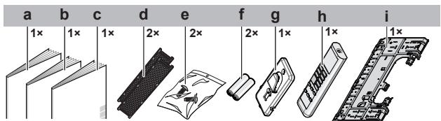
a Installation manual
b Operation manual
c General safety precautions
d Titanium apatite deodorizing and silver particle filter (only for FTXP)
e Indoor unit fixing screw (M4×12L). Refer to "5.5.3 To fix the unit on the mounting plate" on page 10.
f Dry battery AAA.LR03 (alkaline) for user interface
g User interface holder
h User interface
i Mounting plate
3 About the unit

WARNING: FLAMMABLE MATERIAL
The refrigerant inside this unit is mildly flammable.
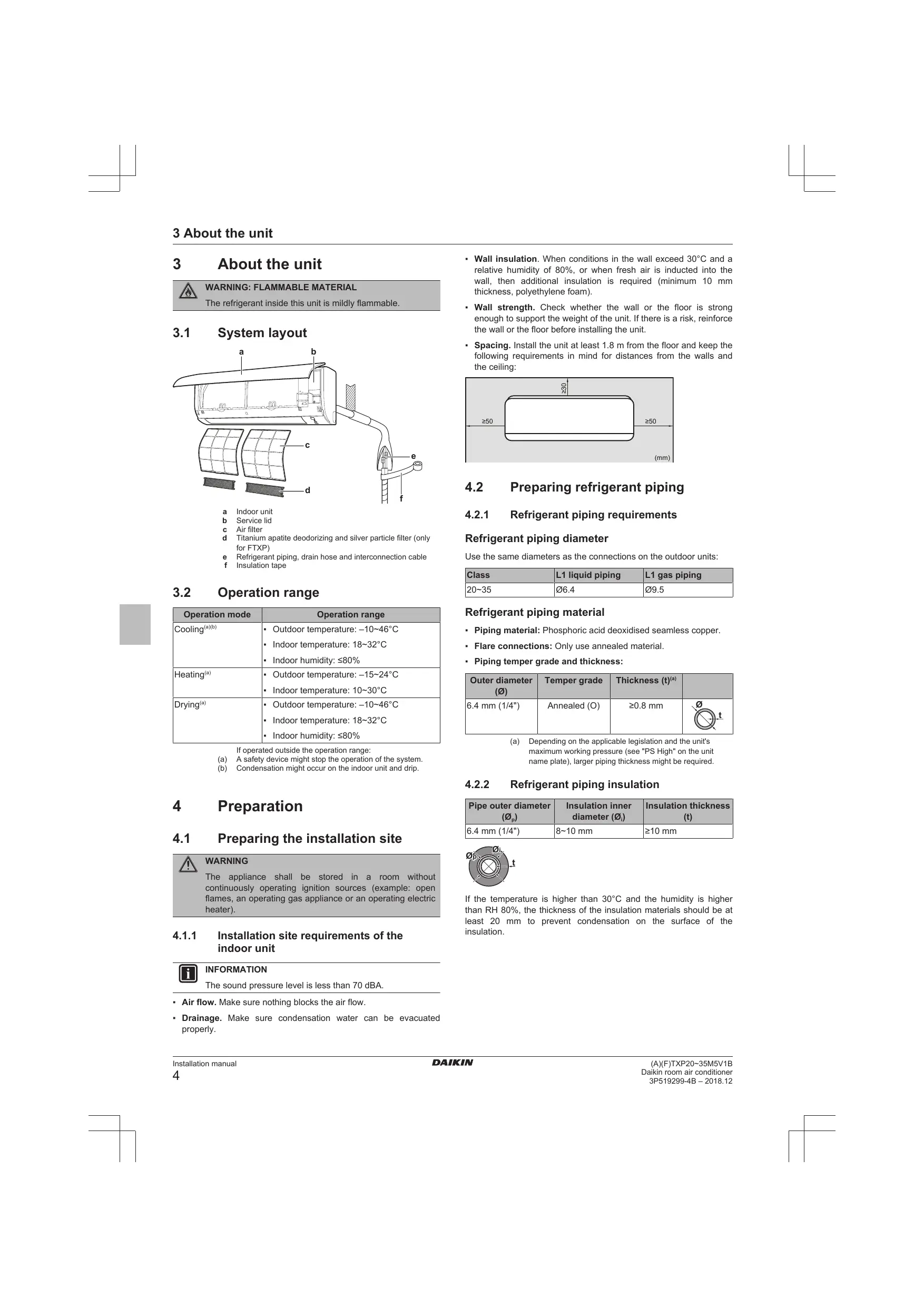
3.1 System layout
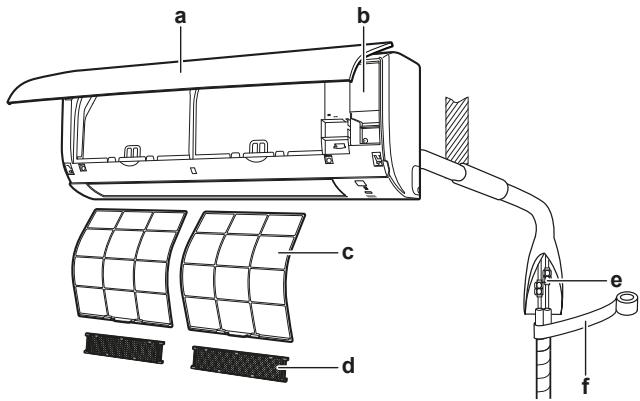
a Indoor unit
b Service lid
c Air filter
d Titanium apatite deodorizing and silver particle filter (only for FTXP)
e Refrigerant piping, drain hose and interconnection cable
f Insulation tape
3.2 Operation range
| Operation mode | Operation range |
| Cooling^(a)(b) | Outdoor temperature: -10 46^ Indoor temperature: 18 32^ Indoor humidity: ≤ 80% |
| Heating^(a) | Outdoor temperature: -15 24^ Indoor temperature: 10 30^ |
| Drying^(a) | Outdoor temperature: -10 46^ Indoor temperature: 18 32^ Indoor humidity: ≤ 80% |
If operated outside the operation range:
(a) A safety device might stop the operation of the system.
(b) Condensation might occur on the indoor unit and drip.
4 Preparation
4.1 Preparing the installation site

WARNING
The appliance shall be stored in a room without continuously operating ignition sources (example: open flames, an operating gas appliance or an operating electric heater).
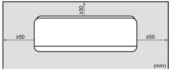
4.1.1 Installation site requirements of the indoor unit

INFORMATION
The sound pressure level is less than 70 dBA.
- Air flow. Make sure nothing blocks the air flow.
-
Drainage. Make sure condensation water can be evacuated properly.
-
Wall insulation. When conditions in the wall exceed 30°C and a relative humidity of 80%, or when fresh air is inducted into the wall, then additional insulation is required (minimum 10 mm thickness, polyethylene foam).
- Wall strength. Check whether the wall or the floor is strong enough to support the weight of the unit. If there is a risk, reinforce the wall or the floor before installing the unit.
- Spacing. Install the unit at least 1.8 m from the floor and keep the following requirements in mind for distances from the walls and the ceiling:
4.2 Preparing refrigerant piping
4.2.1 Refrigerant piping requirements
Refrigerant piping diameter
Use the same diameters as the connections on the outdoor units:
| Class | L1 liquid piping | L1 gas piping |
| 20~35 | ∅6.4 | ∅9.5 |
Refrigerant piping material
- Piping material: Phosphoric acid deoxidised seamless copper.
- Flare connections: Only use annealed material.
- Piping temper grade and thickness:
| Outer diameter (∅) | Temper grade | Thickness (t)(a) | |
| 6.4 mm (1/4") | Annealed (O) | ≥0.8 mm |
(a) Depending on the applicable legislation and the unit's maximum working pressure (see "PS High" on the unit name plate), larger piping thickness might be required.
4.2.2 Refrigerant piping insulation
| Pipe outer diameter ( _p ) | Insulation inner diameter ( _i ) | Insulation thickness (t) |
| 6.4 mm (1/4") | 8~10 mm | ≥10 mm |
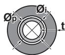
If the temperature is higher than 30^ C and the humidity is higher than RH 80%, the thickness of the insulation materials should be at least 20 mm to prevent condensation on the surface of the insulation.
5 Installation
5.1 Opening the indoor unit
5.1.1 To remove the front panel
1 Hold the front panel by the panel tabs on both sides and open it.
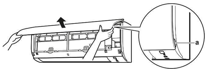
a Panel tabs
2 Remove the front panel by sliding it to the left or the right and pulling it toward you.
Result: The front panel shaft on 1 side will be disconnected.
3 Disconnect the front panel shaft on the other side in the same manner.
natural_image
Technical line drawing of a mechanical component with a tool and bracket (no text or symbols)a Front panel shaft
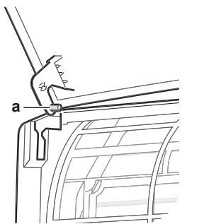
5.1.2 To re-install the front panel
1 Attach the front panel. Align the shafts with the slots and push them all the way in.
2 Close the front panel slowly; press at both sides and at the centre.
5.1.3 To remove the front grille

CAUTION
Wear adequate personal protective equipment (protective gloves, safety glasses,...) when installing, maintaining or servicing the system.
1 Remove the front panel to remove the air filter.
2 Remove 2 screws from the front grille.
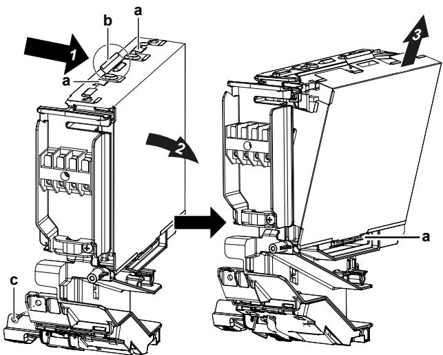
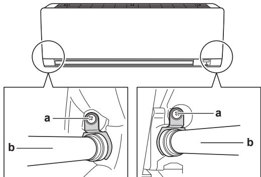
3 Push down the 3 upper hooks marked with a symbol with 3 circles.
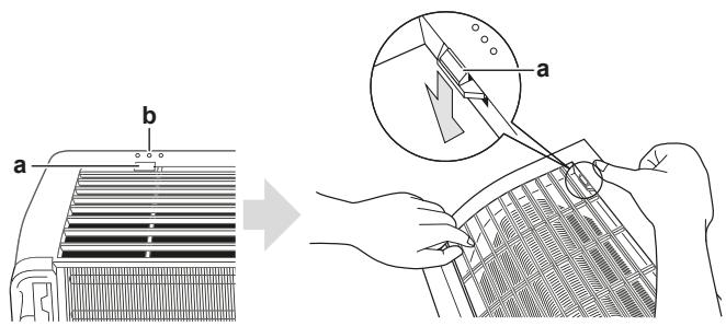
a Upper hook
b Symbol with 3 circles
4 We recommend opening the flap before removing the front grille.
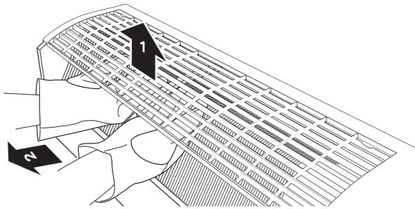
5 Place both hands under the centre of the front grille, push it up and then toward you.
5.1.4 To re-install the front grille
1 Install the front grille and firmly engage the 3 upper hooks.
2 Install 2 screws (class 20\~35) back on the front grille.
3 Install the air filter and then mount the front panel.
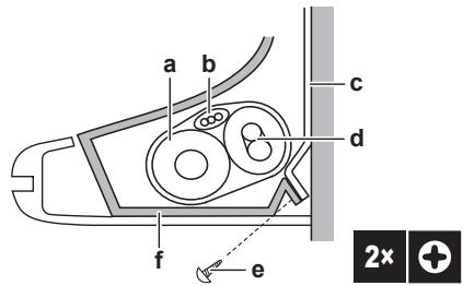
5.1.5 To remove the electrical wiring box cover
1 Remove the front grille.
2 Remove 1 screw from the electrical wiring box.
3 Open the electrical wiring box cover by pulling the protruding part on the top of the cover.
4 Unhook the tab on the bottom and remove the electrical wiring box cover.
a Tab
b Protruding part on the top of the cover
c Screw
5 To re-install the cover, first hook the bottom tab onto the electrical wiring box, and slide the cover into the 2 upper tabs.
5.1.6 To open the service cover
1 Remove 1 screw from the service cover.
2 Pull out the service cover horizontally away from the unit.
a Service cover screw
b Service cover
5.2 Installing the indoor unit
5.2.1 To install the mounting plate
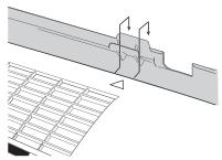
1 Install the mounting plate temporarily.
2 Level the mounting plate.
3 Mark the centres of the drilling points on the wall using a tape measure. Position the end of tape measure at symbol "">".
4 Finish the installation by securing the mounting plate on the wall using M4×25L screws (field supply).

INFORMATION
The removed pipe port cover can be kept in the mounting plate pocket.
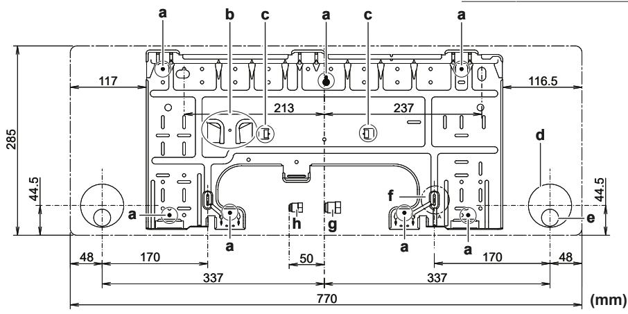
A Class 20\~35
a Recommended mounting plate fixing spots
b Pocket for the pipe port cover
c Tabs for placing a spirit level
d Through-the-wall hole ∅65 mm
e Drain hose position
f Position for the tape measure at symbol "▷"
g Gas pipe end
h Liquid pipe end
5.2.2 To drill a wall hole

CAUTION
For walls containing a metal frame or a metal board, use a wall embedded pipe and wall cover in the feed-through hole to prevent possible heat, electrical shock, or fire.

NOTICE
Be sure to seal the gaps around the pipes with sealing material (field supply), in order to prevent water leakage.
1 Bore a 65 mm large feed-through hole in the wall with a downward slope towards the outside.
2 Insert a wall embedded pipe into the hole.
3 Insert a wall cover into the wall pipe.
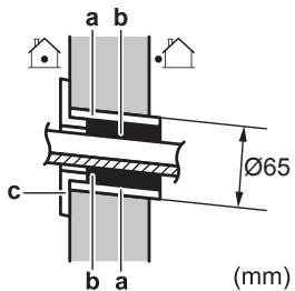
a Wall embedded pipe
b Putty
c Wall hole cover
4 After completing wiring, refrigerant piping and drain piping, do NOT forget to seal the gap with putty.
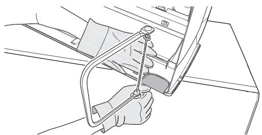
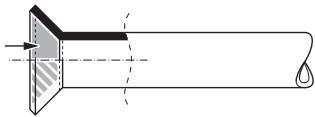
5.2.3 To remove the pipe port cover
To connect the piping on right-side, right-bottom, left-side or left-bottom, the pipe port cover MUST be removed.
1 Cut off the pipe port cover from inside the front grille using a coping saw.
natural_image
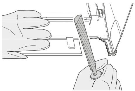
Line drawing of a hand using a tool to adjust or install a mechanical component (no text or symbols visible)2 Remove any burrs along the cut section using a half round needle file.
natural_image
Illustration of hands using a tool to adjust or install a component, no text or symbols present
NOTICE
Do NOT use nippers to remove the pipe port cover, as this would damage the front grille.
5.2.4 To provide drainage
Make sure condensation water can be evacuated properly. This involves:
- General guidelines
- Connecting the drain piping to the indoor unit
- Checking for water leaks
General guidelines
- Pipe length. Keep drain piping as short as possible.
- Pipe size. If drain hose extension or embedded drain piping is required, use appropriate parts that match the hose front end.

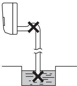
NOTICE
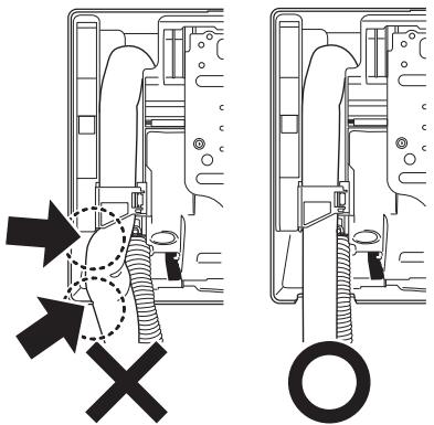
- Install the drain hose with a downward slope.
- Traps are NOT permitted.
- Do NOT put the end of the hose in water.
natural_image
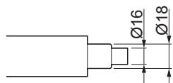
Simple line drawing of a pipe with a valve and cross symbol, partially submerged in liquid (no text or labels)- Drain hose extension. To extend the drain hose, use a field supplied hose with inner ∅16 mm. Do NOT forget to use a heat insulation tube on the indoor section of the extension hose.
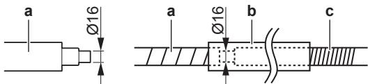
a Drain hose supplied with the indoor unit
b Heat insulation tube (field supply)
c Extension drain hose
- Rigid polyvinyl chloride pipe. When connecting a rigid polyvinyl chloride pipe (nominal ∅13 mm) directly to the drain hose as with embedded piping work, use a field supplied drain socket (nominal ∅13 mm).
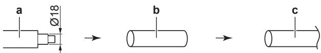
a Drain hose supplied with the indoor unit
b Drain socket with nominal ∅13 mm (field supply)
c Rigid polyvinyl chloride pipe (field supply)
- Condensation. Take measures against condensation. Insulate the complete drain piping in the building.
1 Insert the drain hose in the drain pipe as shown in the following figure, so it will NOT be pulled out of the drain pipe.
To connect the piping on right side, right-back, or right-bottom

INFORMATION
The factory default is right-side piping. For left-side piping, remove the piping from the right side and install it on the left side.
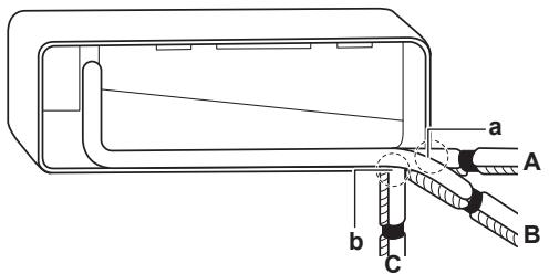
1 Attach the drain hose with adhesive vinyl tape to the bottom of the refrigerant pipes.
2 Wrap the drain hose and the refrigerant pipes together using insulation tape.
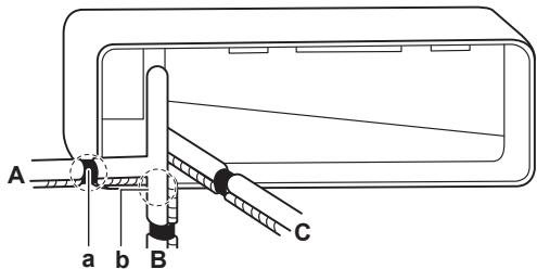
A Right-side piping
B Right-bottom piping
C Right-back piping
a Remove the pipe port cover here for right-side piping.
b Remove the pipe port cover here for right-bottom piping.
To connect the piping on left side, left-back, or left-bottom

INFORMATION
The factory default is right-side piping. For left-side piping, remove the piping from the right side and install it on the left side.
1 Remove the insulation fixing screw on the right side and remove the drain hose.
2 Remove the drain plug on the left side and attach it to the right side.

NOTICE
Do NOT apply lubricating oil (refrigerant oil) to the drain plug when inserting it. The drain plug may deteriorate and cause drain leakage from the plug.
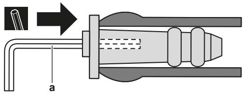
a 4 mm hexagonal wrench
3 Insert the drain hose on the left side and do not forget to tighten it with the fixing screw; otherwise water leakage may occur.
a Insulation fixing screw
b Drain hose
4 Attach the drain hose to the refrigerant pipes bottom side using adhesive vinyl tape.
A Left-side piping
B Left-back piping
C Left-bottom piping
a Remove the pipe port cover here for left-side piping.
b Remove the pipe port cover here for left-bottom piping.
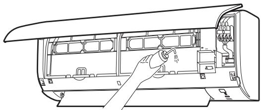
To check for water leaks
1 Remove the air filters.
2 Gradually pour approximately 1 l of water in the drain pan, and check for water leaks.
natural_image
Line drawing of a hand inserting a plug into an air conditioner unit (no text or symbols)5.3 Connecting the refrigerant piping

DANGER: RISK OF BURNING
5.3.1 Guidelines when connecting the refrigerant piping
Take the following guidelines into account when connecting pipes:
- Coat the flare inner surface with ether oil or ester oil when connecting a flare nut. Tighten 3 or 4 turns by hand, before tightening firmly.
- ALWAYS use 2 wrenches together when loosening a flare nut.
- ALWAYS use a spanner and torque wrench together to tighten the flare nut when connecting the piping. This to prevent nut cracking and leaks.
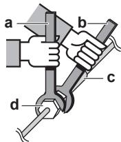
a Torque wrench
b Spanner
c Piping union
d Flare nut
| Piping size (mm) | Tightening torque (N·m) | Flare dimensions (A) (mm) | Flare shape (mm) |
| ∅6.4 | 15~17 | 8.7~9.1 | 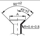 |
| ∅9.5 | 33~39 | 12.8~13.2 | |
| ∅12.7 | 50~60 | 16.2~16.6 |
5.3.2 To connect the refrigerant piping to the indoor unit
- Pipe length. Keep refrigerant piping as short as possible.
- Flare connections. Connect refrigerant piping to the unit using flare connections.
- Insulation. Insulate the refrigerant piping, interconnection cable and drain hose on the indoor unit as follows:
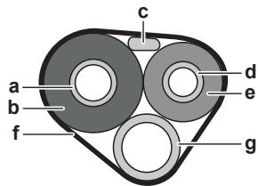
a Gas pipe
b Gas pipe insulation
c Interconnection cable
d Liquid pipe
e Liquid pipe insulation
f Finishing tape
g Drain hose

NOTICE
Make sure to insulate all refrigerant piping. Any exposed piping might cause condensation.
5.4 Connecting the electrical wiring

DANGER: RISK OF ELECTROCUTION

WARNING
ALWAYS use multicore cable for power supply cables.

WARNING
If the supply cord is damaged, it MUST be replaced by the manufacturer, its service agent or similarly qualified persons in order to avoid a hazard.

WARNING
Do NOT connect the power supply to the indoor unit. This could result in electrical shock or fire.

WARNING
- Do NOT use locally purchased electrical parts inside the product.
- Do NOT branch the power supply for the drain pump, etc. from the terminal block. This could result in electrical shock or fire.

WARNING
Keep the interconnection wiring away from copper pipes without thermal insulation as such pipes will be very hot.
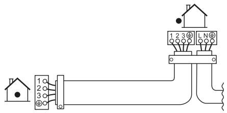
5.4.1 To connect the electrical wiring on the indoor unit
Electrical work should be carried out in accordance with the installation manual and the national electrical wiring rules or code of practice.
1 Set the indoor unit on the mounting plate hooks. Use the "△" marks as a guide.
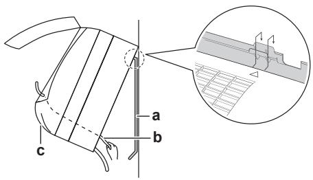
a Mounting plate (accessory)
b Interconnection cable
c Wire guide
2 Open the front panel, and then the service cover. Refer to "5.1 Opening the indoor unit" on page 5.
3 Pass the interconnection cable from the outdoor unit through the feed-through wall hole, through the back of the indoor unit and through the front side.
Note: In case the interconnection cable was stripped in advance, cover the ends with insulating tape.
4 Bend the end of the cable up.

NOTICE
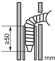
- Be sure to keep the power line and transmission line apart from each other. Transmission wiring and power supply wiring may cross, but may NOT run parallel.
- In order to avoid any electrical interference the distance between both wirings should ALWAYS be at least 50 mm.

WARNING
Provide adequate measures to prevent that the unit can be used as a shelter by small animals. Small animals that make contact with electrical parts can cause malfunctions, smoke or fire.
5 Strip the wire ends approximately 15 mm.
6 Match wire colours with terminal numbers on the indoor unit terminal blocks and firmly screw the wires to the corresponding terminals.
7 Connect the earth wire to the corresponding terminal.
8 Firmly fix the wires with the terminal screws.
9 Pull the wires to make sure that they are securely attached, then retain the wires with the wire retainer.
10 Shape the wires so that the service cover fits securely, then close the service cover.
5.5 Finishing the indoor unit installation
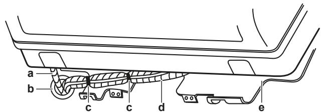
5.5.1 To insulate the drain piping, refrigerant piping and interconnection cable
1 After the drain piping, refrigerant piping and the electrical wiring are finished. Wrap refrigerant pipes, interconnection cable and drain hose together using insulation tape. Overlap at least half the width of the tape with each turn.
a Drain hose
b Interconnection cable
c Mounting plate (accessory)
d Refrigerant pipes
e Indoor unit fixing screw M4×12L (accessory)
f Bottom frame
5.5.2 To pass the pipes through the wall hole
1 Shape the refrigerant pipes along the pipe path marking on the mounting plate.
a Drain hose
b Caulk this hole with putty or caulking material.
c Adhesive vinyl tape
d Insulation tape
e Mounting plate (accessory)

NOTICE
- Do NOT bend refrigerant pipes.
- Do NOT push the refrigerant pipes onto the bottom frame or the front grille.
2 Pass the drain hose and refrigerant pipes through the wall hole.
5.5.3 To fix the unit on the mounting plate
1 Set the indoor unit on the mounting plate hooks. Use the "△" marks as a guide.
2 Press the bottom frame of the unit with both hands to set it on the bottom hooks of the mounting plate. Make sure that the wires do NOT get squeezed anywhere.
Note: Take care that the interconnection cable does NOT get caught in the indoor unit.
3 Press the bottom edge of the indoor unit with both hands until it is firmly caught by the mounting plate hooks.
4 Secure the indoor unit to the mounting plate using 2 indoor unit fixing screws M4×12L (accessory).
6 Configuration
6.1 To set a different address
In case 2 indoor units are installed in 1 room, different addresses for 2 user interfaces can be set.
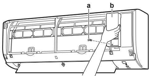
1 Remove the batteries from the user interface.
2 Cut the address jumper.
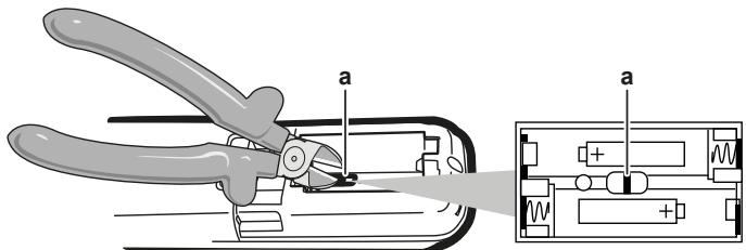
a Address jumper

NOTICE
Be careful NOT to damage any of the surrounding parts when cutting the address jumper.
3 Turn the power supply on.
Result: The flap of the indoor unit will open and close to set the reference position.

INFORMATION
- For FTXF units, the following setting MUST be completed within 5 minutes after the power supply is turned on.
- In case you could NOT complete the setting in time, turn the power supply off and wait at least 1 minute before turning the power supply back on.
4 Press simultaneously:
| Model | Buttons |
| FTXP and ATXP | |
| FTXF |
5 Press:
| Model | Button |
| FTXP and ATXP |
| Model | Button |
| FTXF | MODE |
6 Select:
| Model | Symbol |
| FTXP and ATXP | R |
| FTXF | 7^- |
7 Press:
| Model | Button |
| FTXP and ATXP | FAN |
| FTXF |

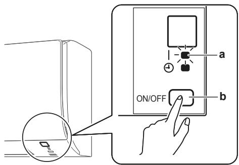
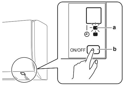
a Operation lamp
b Indoor unit ON/OFF switch
8 Press the indoor unit ON/OFF switch while the operation lamp is blinking.
| Jumper | Address |
| Factory setting | 1 |
| After cutting with nippers | 2 |

INFORMATION
If the setting could NOT be completed while the operation lamp was blinking, repeat the setting process from the beginning.
9 When the setting is complete, press:
| Model | Button |
| FTXP and ATXP | Keep ✿FAN pressed for about 5 seconds. |
| FTXF |
Result: The user interface will return to the previous screen.
10 Press simultaneously:
| Model | Buttons |
| FTXP | |
| FTXF |
11 Press:
| Model | Button |
| FTXP | |
| FTXF |
12 Select:
| Model | Symbol |
| FTXP | R |
| FTXF | ? |
13 Press:
| Model | Button |
| FTXP | |
| FTXF |
a Operation lamp
b Indoor unit ON/OFF switch
14 Press the indoor unit ON/OFF switch while the operation lamp is blinking.
| Jumper | Address |
| Factory setting | 1 |
| After cutting with nippers | 2 |

INFORMATION
If the setting could NOT be completed while the operation lamp was blinking, repeat the setting process from the beginning.
15 When the setting is complete, press:
| Model | Button |
| FTXP | Keep ✉FAN pressed for about 5 seconds. |
| FTXF |
Result: The user interface will return to the previous screen.
7 Commissioning

NOTICE
NEVER operate the unit without thermistors and/or pressure sensors/switches. Burning of the compressor might result.
7.1 Checklist before commissioning
Do NOT operate the system before the following checks are OK:
| You read the complete installation instructions, as described in theinstaller reference guide. | |
| Theindoor unitsare properly mounted. | |
| Theoutdoor unitis properly mounted. | |
| Air inlet/outletCheck that the air inlet and outlet of the unit is NOT obstructed by paper sheets, cardboard, or any other material. | |
| There are NOMissing phasesor reversed phases. | |
| Therefrigerant pipes(gas and liquid) are thermally insulated. |
| ☐ | DrainageMake sure drainage flows smoothly.Possible consequence: Condensate water might drip. |
| ☐ | The system is properly earthed and the earth terminals are tightened. |
| ☐ | The fuses or locally installed protection devices are installed according to this document, and have NOT been bypassed. |
| ☐ | The power supply voltage matches the voltage on the identification label of the unit. |
| ☐ | The specified wires are used for the interconnection cable. |
| ☐ | The indoor unit receives the signals of the user interface. |
| ☐ | There are NO loose connections or damaged electrical components in the switch box. |
| ☐ | The insulation resistance of the compressor is OK. |
| ☐ | There are NO damaged components or squeezed pipes on the inside of the indoor and outdoor units. |
| ☐ | There are NO refrigerant leaks. |
| ☐ | The correct pipe size is installed and the pipes are properly insulated. |
| ☐ | The stop valves (gas and liquid) on the outdoor unit are fully open. |
7.2 To perform a test run
Prerequisite: Power supply MUST be in the specified range.
Prerequisite: Test run may be performed in cooling or heating mode.
Prerequisite: Test run should be performed in accordance with the operation manual of the indoor unit to make sure that all functions and parts are working properly.
1 In cooling mode, select the lowest programmable temperature. In heating mode, select the highest programmable temperature. Test run can be disabled if necessary.
2 When the test run is finished, set the temperature to a normal level. In cooling mode: 26\~28°C, in heating mode: 20\~24°C.
3 The system stops operating 3 minutes after the unit is turned OFF.
7.2.1 To perform a test run in winter season
When operating the air conditioner in Cooling mode in winter, set it to test run operation using the following method.
For FTXP units
1 Press , , and OFF simultaneously.
2 Press
3 Select 7.
4 Press FAN
5 Press COOL to switch the system on.
Result: Test run operation will stop automatically after about 30 minutes.
6 To stop operation, press OFF.
For FTXF units
7 Press to switch the system on.
8 Press the centre of , , and MODE simultaneously.
9 Press MODE twice.
Result: 7 will appear on the display. Test run operation is selected. Test run operation will stop automatically after about 30 minutes.
10 To stop operation, press.

INFORMATION
Some of the functions CANNOT be used in the test run operation mode.
If a power failure occurs during operation, the system automatically restarts immediately after power is restored.
8 Disposal
Dismantling of the unit and treatment of the refrigerant, oil and other parts MUST comply with the applicable legislation.
9 Technical data
A subset of the latest technical data is available on the regional Daikin website (publicly accessible). The full set of latest technical data is available on the Daikin Business Portal (authentication required).
9.1 Wiring diagram
| Unified Wiring Diagram Legend | ||||
| For applied parts and numbering, refer to the wiring diagram on the unit. Part numbering is by Arabic numbers in ascending order for each part and is represented in the overview below by symbol “*” in the part code. | ||||
 | : CIRCUIT BREAKER | CNC0 | : PROTECTIVE EARTH | |
| (NBR) | : CONNECTION | (CDDT) | : PROTECTIVE EARTH (SCREW) | |
| (HTXK) | : CONNECTOR | (HCYT) | : RECTIFIER | |
| (CBD) | : EARTH | (BAD) | : RELAY CONNECTOR | |
| (VBN) | : FIELD WIRING | (KVZT) | : SHORT-CIRCUIT CONNECTOR | |
| (SABCD) | : FUSE | (GND) | : TERMINAL | |
 | : INDOOR UNIT | (TNTD) | : TERMINAL STRIP | |
| INDOOR | ||||
 | : OUTDOOR UNIT | (BND) | : WIRE CLAMP | |
| OUTDOOR | ||||
| BLK : BLACK | GRN : GREEN | PNK : PINK | WHT : WHITE | |
| BLU : BLUE | GRY : GREY | PRP, PPL : PURPLE | YLW : YELLOW | |
| BRN : BROWN | ORG : ORANGE | RED : RED | ||
| A*P | : PRINTED CIRCUIT BOARD | PS | : SWITCHING POWER SUPPLY | |
| BS* | : PUSHBUTTON ON/OFF, OPERATION SWITCH | PTC* | : THERMISTOR PTC | |
| BZ, H*O | : BUZZER | Q* | : INSULATED GATE BIPOLAR TRANSISTOR | |
| C* | : CAPACITOR | (IGBT) | ||
| AC*, CN*, E*, HA*, HE*, HL*, HN*, HR*, MR*, A, MR*, B, S*, U, V, W, X*, A, K*R_* | : CONNECTION, CONNECTOR | Q*DI | : EARTH LEAK CIRCUIT BREAKER | |
| Q*L | : OVERLOAD PROTECTOR | |||
| Q*M | : THERMO SWITCH | |||
| D*, V*D | : DIODE | R* | : RESISTOR | |
| DB* | : DIODE BRIDGE | R*T | : THERMISTOR | |
| DS* | : DIP SWITCH | RC | : RECEIVER | |
| E*H | : HEATER | S*C | : LIMIT SWITCH | |
| F*U, FU* (FOR CHARACTERISTICS, REFER TO PCB INSIDE YOUR UNIT) | : FUSE | S*L | : FLOAT SWITCH | |
| S*NPH | : PRESSURE SENSOR (HIGH) | |||
| FG* | : CONNECTOR (FRAME GROUND) | S*NPL | : PRESSURE SENSOR (LOW) | |
| H* | : HARNESS | S*PH, HPS* | : PRESSURE SWITCH (HIGH) | |
| H*P, LED*, V*L | : PILOT LAMP, LIGHT EMITTING DIODE | S*PL | : PRESSURE SWITCH (LOW) | |
| HAP | : LIGHT EMITTING DIODE (SERVICE MONITOR GREEN) | S*T | : THERMOSTAT | |
| HIGH VOLTAGE | : HIGH VOLTAGE | S*RH | : HUMIDITY SENSOR | |
| IES | : INTELLIGENT EYE SENSOR | S*W, SW* | : OPERATION SWITCH | |
| IPM* | : INTELLIGENT POWER MODULE | SA*, F1S | : SURGE ARRESTOR | |
| K*R, KCR, KFR, KHuR, K*M | : MAGNETIC RELAY | SR*, WLU | : SIGNAL RECEIVER | |
| L | : LIVE | SS* | : SELECTOR SWITCH | |
| L* | : COIL | SHEET METAL | : TERMINAL STRIP FIXED PLATE | |
| L*R | : REACTOR | T*R | : TRANSFORMER | |
| M* | : STEPPER MOTOR | TC, TRC | : TRANSMITTER | |
| M*C | : COMPRESSOR MOTOR | V*, R*V | : VARISTOR | |
| M*F | : FAN MOTOR | V*R | : DIODE BRIDGE | |
| M*P | : DRAIN PUMP MOTOR | WRC | : WIRELESS REMOTE CONTROLLER | |
| M*S | : SWING MOTOR | X* | : TERMINAL | |
| MR*, MRCW*, MRM*, MRN* | : MAGNETIC RELAY | X*M | : TERMINAL STRIP (BLOCK) | |
| N | : NEUTRAL | Y*E | : ELECTRONIC EXPANSION VALVE COIL | |
| n=*, N=* | : NUMBER OF PASSES THROUGH FERRITE CORE | Y*R, Y*S | : REVERSING SOLENOID VALVE COIL | |
| PAM | : PULSE-AMPLITUDE MODULATION | Z*C | : FERRITE CORE | |
| PCB* | : PRINTED CIRCUIT BOARD | ZF, Z*F | : NOISE FILTER | |
| PM* | : POWER MODULE | |||
Inhaltsverzeichnis
a Blendenlaschen
a Frontblendenwelle
natural_image
Illustration of a hand using a tool to adjust or install a mechanical component (no text or symbols visible)natural_image
Illustration of hands using a tool to adjust or install electronic components (no text or symbols visible)
HINWEIS
natural_image
Simple line drawing of a pipe with a valve and cross symbol, partially submerged in liquid (no text or labels)natural_image
Line drawing of an air conditioner unit with a hand inserting a plug into the chamber (no text or symbols)GEFAHR: STROMSCHLAGGEFAHR

WARNUNG
a Crochet supérieur
a Languette
natural_image
Illustration of hands using a tool to adjust or install a mechanical component (no text or symbols visible)natural_image
Illustration of hands using a tool to adjust or install electronic components (no text or symbols visible)
REMARQUE
natural_image
Simple line drawing of a pipe with a valve and cross symbol, partially submerged in liquid (no text or labels)natural_image
Line drawing of a car interior showing a hand inserting a plug into the air gap (no text or symbols)WAARSCHUWING: ONTVLAMBAAR MATERIAAL
a Paneeltabs
natural_image
Illustration of a person using a saw to cut or install a piece of wood, no text or symbols presentnatural_image
Illustration of hands using a tool to adjust or install electronic components (no text or symbols visible)
OPMERKING
natural_image
Simple line drawing of a pipe with a valve and cross symbol, partially submerged in liquid (no text or labels)natural_image
Line drawing of a hand inserting a plug into an air conditioner unit (no text or symbols)a Adresjumper

OPMERKING
a Pestañas de panel
natural_image
Illustration of hands using a tool to cut or install a mechanical component (no text or symbols visible)natural_image
Illustration of hands using a tool to adjust or install a component, no text or symbols present
AVISO
natural_image
Simple line drawing of a pipe with a valve and cross symbol, partially submerged in liquid (no text or labels)natural_image
Line drawing of an air conditioner unit with a hand inserting a plug into the chamber (no text or symbols)
natural_image
Technical line drawing of a mechanical device with no visible text or symbolsa Linguette del pannello
natural_image
Illustration of a hand using a tool to adjust or install a mechanical component (no text or symbols visible)natural_image
Illustration of hands using a tool to adjust or install electronic components (no text or symbols visible)
NOTA
natural_image
Simple line drawing of a pipe with a valve and cross symbol, partially submerged in liquid (no text or labels)natural_image
Line drawing of an air conditioner unit with a hand inserting a plug into the chamber (no text or symbols)natural_image
Illustration of a hand using a tool to cut or install a mechanical component (no text or symbols visible)natural_image
Illustration of hands using a tool to adjust or install a mechanical component (no text or symbols visible)
ΕΙΔΟΠΟΙΗΣΗ
natural_image
Simple line drawing of a pipe with a valve and cross symbol, partially submerged in liquid (no text or labels)natural_image
Line drawing of a car interior showing the engine compartment with a hand inserting a plug into the air gap (no text or symbols)natural_image
Illustration of a hand using a tool to adjust or install a mechanical component (no text or symbols visible)natural_image
Illustration of hands using a tool to adjust or install a component, no text or symbols present
NOTIFICAÇÃO
natural_image
Simple line drawing of a pipe or pipe passing through a container with a valve, no text or symbols present.natural_image
Line drawing of a hand inserting a plug into an air conditioner unit (no text or symbols)natural_image
Diagram of a mechanical device with directional arrows and a cross mark, no readable text or symbols present.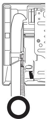
natural_image
Technical line drawing of a mechanical assembly with no visible text or symbolsa Выступы панели
natural_image
Illustration of a hand using a tool to cut or install a mechanical component (no text or symbols visible)natural_image
Illustration of hands using a tool to adjust or install a mechanical component (no text or symbols visible)
ПРИМЕЧАНИЕ
natural_image
Simple line drawing of a pipe with a valve and cross symbol, partially submerged in liquid (no text or labels)natural_image
Line drawing of an air conditioner unit with a hand inserting a plug into the chamber (no text or symbols)a Panel tırnakları
a Üst kanca
b 3 daireli sembol
natural_image
Illustration of a person using a tool to adjust or install a mechanical component (no text or symbols visible)natural_image
Illustration of hands using a tool to adjust or install a mechanical component (no text or symbols visible)
BİLDİRİM
natural_image
Simple line drawing of a pipe or pipe passing through a container with a valve, no text or symbols present.natural_image
Line drawing of an air conditioner unit with a hand inserting a plug into the chamber (no text or symbols)natural_image
Diagram of a mechanical device with arrows indicating force or movement, no readable text or symbols present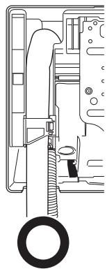
natural_image
Technical line drawing of a mechanical assembly with no visible text or symbolsa Adres atlatma teli

BİLDİRİM
| Model | Sembol |
| FTXP | 8 |
| FTXF | 7* |
13 Basin:
| Model | Düğme |
| FTXP | |
| FTXF |