USER MANUAL TOEQ30 EQUATION
Hors France/ Not included for France
ATLANTIC POLSKA Sp. zo.o.
ul. Ptochocińska 99
03-044 Varsovie
Pologne
Tel. 022 811 82 60
CENTRAL SERVICE INSTAL
Centre d'appels 24h/24 : 0372.123.123; 08010.123.123
service.romstal@csiservice.ro
nr., Soseaua Vitan-Bárzeşti 11A, Bucarest 042122, Roumanie
ATLANTIC POLSKA Sp. z o.o.
ul.Plochocińska 99
03-044 Warszawa
Polonia
Tel. 022 811 82 60
ATLANTIC POLSKA Sp. z o.o.
ul.Ptochocinska 99
03-044 Varsóvia
Polonia
Tel. 022 811 82 60
CENTRAL SERVICE INSTAL
Centro de atendimento 24h/dia:0372.123.123;08010.123.123
service.romstal@csiservice.ro
nr., Soseaua Vitan-Bárzesti 11A, Bucuresti 042122, Romania
ATLANTIC POLSKA Sp. z o.o.
ul.Ptochocińska 99
03-044 Warszawa
Polska
Tel. 022 811 82 60
CENTRAL SERVICE INSTAL
Call center 24 h:0372.123.123;08010.123.123
service.romstal@csiservice.ro
nr., Soseaua Vitan-Bárzeesti 11A, Bucuresti 042122, Romania
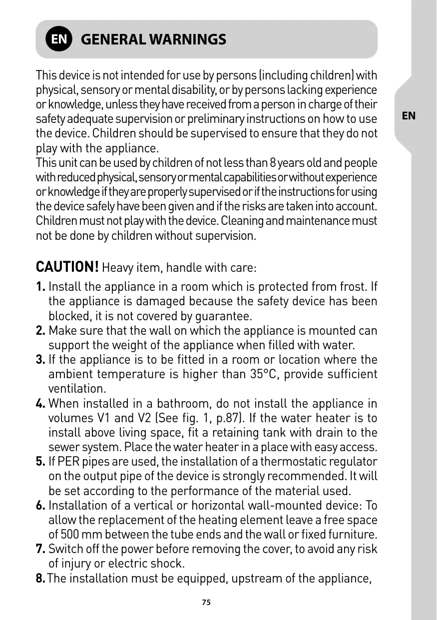
This device is not intended for use by persons (including children) with physical, sensory or mental disability, or by persons lacking experience or knowledge, unless they have received from a person in charge of their safety adequate supervision or preliminary instructions on how to use the device. Children should be supervised to ensure that they do not play with the appliance.
This unit can be used by children of not less than 8 years old and people with reduced physical, sensory or mental capabilities or without experience or knowledge if they are properly supervised or if the instructions for using the device safely have been given and if the risks are taken into account. Children must not play with the device. Cleaning and maintenance must not be done by children without supervision.
CAUTION! Heavy item, handle with care:
- Install the appliance in a room which is protected from frost. If the appliance is damaged because the safety device has been blocked, it is not covered by guarantee.
- Make sure that the wall on which the appliance is mounted can support the weight of the appliance when filled with water.
- If the appliance is to be fitted in a room or location where the ambient temperature is higher than 35^ , provide sufficient ventilation.
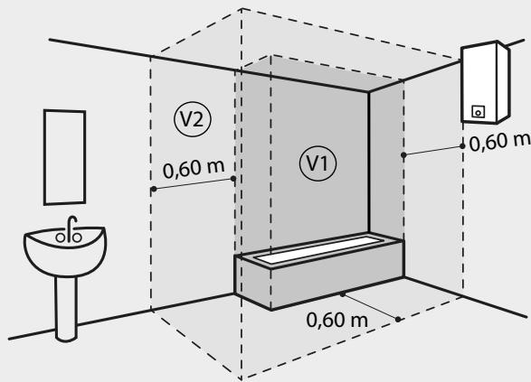
- When installed in a bathroom, do not install the appliance in volumes V1 and V2 (See fig. 1, p.87). If the water heater is to install above living space, fit a retaining tank with drain to the sewer system. Place the water heater in a place with easy access.
- If PER pipes are used, the installation of a thermostatic regulator on the output pipe of the device is strongly recommended. It will be set according to the performance of the material used.
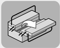
- Installation of a vertical or horizontal wall-mounted device: To allow the replacement of the heating element leave a free space of 500mm between the tube ends and the wall or fixed furniture.
- Switch off the power before removing the cover, to avoid any risk of injury or electric shock.
- The installation must be equipped, upstream of the appliance,
with a bipolar cut-out device (fuse, breaker switch) respecting local regulations (30 mA earth-leakage breaker).
- If the supply cord is damaged, it must be replaced by a special cord or assembly available from the manufacturer or the after sales service.
- Mandatory installation of a safety device in a frost free location (or any other new device which limits the tank pressure) to 0.7 or 0.8MPa (7 or 8 bar) according to the nominal pressure, with a size of 1/2 in the input of the water heater, respecting the local regulations.
- Operate regularly the discharge of safety device to prevent scaling and check that it is not blocked.
- Hydraulic accessories should not be located between the safety valve and the cold water inlet. A pressure reducer (not supplied) is required when the water supply pressure exceeds 0,5MPa (5 bar) and will be fitted on the main supply.
- Connect the safety device to an unpressurised outlet pipe in a frost free location, with a continuous slope to evacuate water during heating up or draining the water heater.
- The pipes used must support 1 MPa (10 bar) and 100^ .
- Never power the water heater without water.
- To drain the device: Switch off the power and the supply of cold water, open the hot water faucets and manipulate the safety valve.
- The products described in this manual are subject to changes at any time to be in accordance with technology and standards. The devices comply with Electromagnetic Directive 2014/30/UE, Low Voltage Directive 2014/35/UE, Directive 2011/65/UE for RoHS and Regulation 2013/814/UE supplementing Directive 2009/125/EC for ecodesign.
- Processing waste electrical and electronic equipment at end of life (Applicable in member states of the EU).
This pictogram means the product must not be processed with unsorted household waste. An obligatory system of disposal and processing of waste electrical and electronic equipment has been implemented, including the duty to recover used equipment free of charge when a new item of equipment is purchased, and selective collection by an approved organisation. For further information, you can contact your local supplier or local authority. Proper removal of waste electrical and electronic
equipment ensures proper processing and repurposing, thus avoiding damage to the environment and harm to human health, and protecting natural resources.
- This product is intended for use at a maximum altitude of 2000 m.
- Always connect the earth conductor of the cable to the earth ground or connect the earth conductor to the appropriate terminal identified by the symbol .
- The instruction book of this product is available by contacting the after-sales service (page 81).
- See installation diagram (pages 87 and 88).
EN INSTALLATION
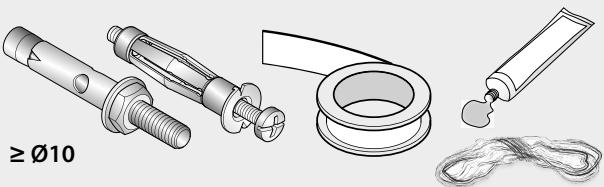
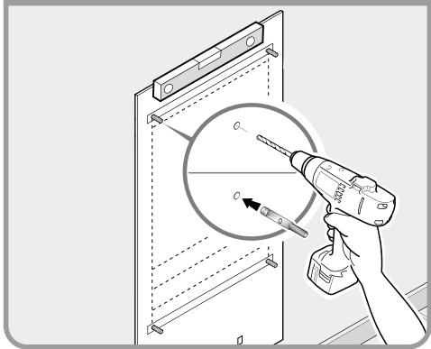
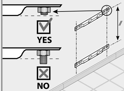
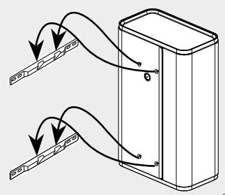
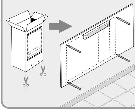
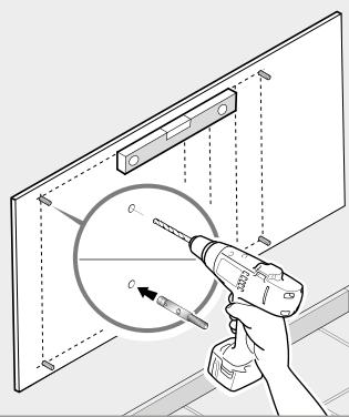
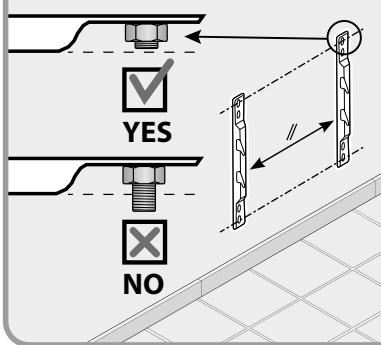
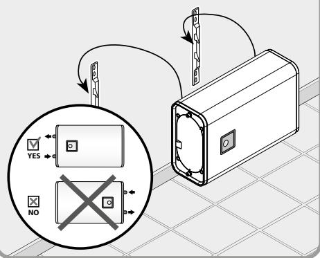
1. PRODUCT MOUNTING See "GeneralWarnings" N°.1 to N°.6
For product installation, refer to drawings section 1 page 87 and page 88.
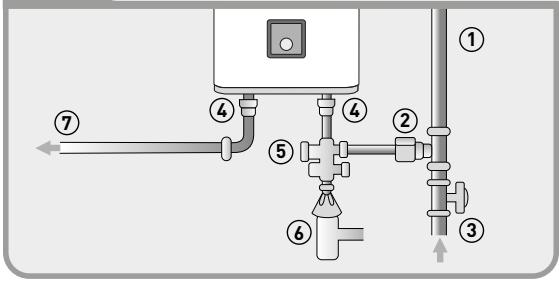
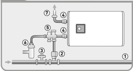
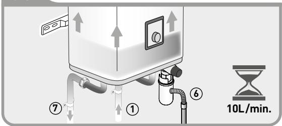
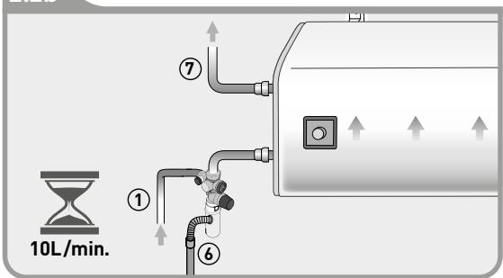
2. HYDRAULIC CONNECTION See "GeneralWarnings" N°.10 to N°.14
For hydraulic connection, refer to drawings section 2 page 91.
- It is necessary to clean the supply piping prior to the hydraulic connection. The connection to the hot water outlet is to be carried out with a dielectric connector, to avoid corrosion of the pipe (direct contact iron / copper). The use of brass fittings is prohibited. The installation must include a pressure reducer, if the supply pressure is greater than 0.5 MPa (5 bar). The pressure reducer must be fitted to the outlet of the main distribution supply. A pressure of 0.3 to 0.4 MPa (3 to 4 bar) is recommended.
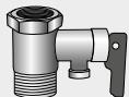
- Always install a new safety device on the cold water pipe of the water heater, which comply with the standards (EN 1487 in Europe), with a maximal pressure of 0.7 or 0.8 MPa (7 or 8 bar) according to the nominal pressure, with diameter 1/2" .
- CAUTION: Do not use the safety valve included in this packaging in France (home country and French overseas).
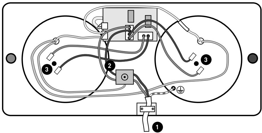
3. ELECTRICAL CONNECTION
For electrical connection, refer to drawings section 3 page 93.
- The water heater can be connected and operated only on AC 230 V. Connect the heater with a rigid cable with conductors 2,5mm^2 . Use a standardised channeling (rigid or flexible conduit) until the calibrated housing cover.
- Directly connect devices with a cable or plug. In France, a product with plug is strictly prohibited and cannot be installed.
- Always connect the earth conductor of the cable to the earth ground wire or connect the earth conductor to the appropriate terminal identified by the symbol (12) . This connection is compulsory for safety reasons. The earth wire green - yellow must be longer than those of phases. The installation must be
equipped, upstream of the appliance, with a bipolar cut-out device (minimum contact distance of 3 mm fuse, breaker switch).
Thermal circuit breaker (see drawings section 3 page 93): All our products are equipped with a thermostat with thermal circuit breaker and manual resetting which cuts off the power supply to the water heater in case of overheating. If the safety trips:
switch off the power before taking any further action,
remove the cover,
check the electrical connections,
reset the thermal circuit breaker.
If the circuit breaker keeps tripping, replace the thermostat. Never short circuit the safety cut out or the thermostat. Connect the power supply only via the terminal.

SET-UP & OPERATION
-
CAUTION! NEVER POWER THE WATER HEATER WITHOUT WATER: Models with an electric heating element will be certainly damaged.
-
Fill the tank completely. Before powering up, open the hot water taps, drain the pipes in order to empty the air.
- Check the tightness of the tubes and of the flange seal under the plastic cover. In case of leaking tighten moderately. Check the operating of the hydraulic components and of the safety valve.
-
Turn the power on. After 15 to 30 minutes, depending on the capacity of the device, the water should drip from the drain. This is normal and due to the expansion of water. Check connection leaks and seal. During heating and according to the water quality, hot water tanks can make a bubbling noise. This noise is normal and does not indicate any defect of the unit.
-
SETTING KNOB (See drawings A and C page 94): Manual selection of temperature setpoint. Position of reference. C is the maximum position of temperature setting.
- FROST FREE MODE (See drawing B page 94): Automatic regulation at frost-free temperature (7^) , in order to reduce the electric consumption during the periods of absence of the user.
- HEATING LIGHT INDICATOR (See drawing D page 94): Illuminates when the heating process is on.
CAUTION: Before removing the plastic cover, make sure the power is turned off to avoid any risk of injury or electric shock.
1. USER MAINTENANCE
Operates once a month the discharge of the safety valve to prevent scaling deposit and verify that the safety device is not blocked. If this is not done, damage may be caused and the guarantee invalidated. For an installation with a booster pump; before starting up, after a long period of disuse, turn the rotor following the advice in the manufacturer's instructions.
2. MAINTENANCE BY A QUALIFIED PERSON
- Scaling: Remove the scale sludge. Do not scrape or hammer the lime scale deposited on the casing, as this may damage the lining.
- Magnesium anode: Change the magnesium anode every 2 years or when its diameter is lower than 10 ~mm .
- Heating element: The replacement of a sheathed heating element involves draining of the water heater and replacement of the flange gasket. Reassemble the heating element, reasonably tight nuts (cross tightening), check that there is no leakage after the first heating-up, tighten again if necessary.
- Drain: Turn off power and cold water supply. Open hot water taps and drain valve of the safety device.
Spare parts list: Flange gasket, magnesium anode (reference section 5 page 95).
Advice to the user
When the water has a TH > 20^ , it is recommended to treat it with a softener. When a softener is used, the water hardness must remain above 15^ .
In case of prolonged absence, especially in winter, drain your appliance following the procedure above.

SCOPE OF THE GUARANTEE
The water heater must be installed, used and maintained according to best practice and conform to the standards in force in the country in which it is installed and to the instructions contained in this document.
In the European Union this appliance is covered by the statutory guarantee accorded to consumers in accordance with directive 1999/44/CE. This guarantee comes into force when the appliance is delivered to the consumer. In addition to the legal guarantee, certain items are covered by an extra guarantee relating only to the free exchange of the tank and of components accepted as defective. It does not include the cost of replacement or carriage.
Refer to the table below. This commercial guarantee does not affect your statutory rights. It applies within the country where the product was acquired, provided if it is also installed in the same country. The dealer must be informed of any damage before the product is exchanged under guarantee and the appliance will remain available for inspection by experts from the insurance company and the manufacturer.
| Statutory guarantee | 2 years |
| Extra commercial guarantee on enamel tank | +3 years |
Exclusions: Wear parts: Magnesium anodes. Equipment which can not be assessed (access difficult for repair, maintenance or assessment). Equipment exposed to abnormal environmental conditions: Frost, bad weather, water which is abnormally aggressive or outside drinking standards, electrical supply with large spikes. Equipment installed without observing current standards in the country of installation: The absence or incorrect fitting of safety devices, abnormal corrosion due to incorrect water fitments (iron/copper contact), incorrect earthing, inadequate cable thickness, non-observance of the connection drawings shown in these instructions.
Equipment not maintained in accordance with these instructions. Repairs or replacement of parts or components in the equipment not carried out or authorised by the company responsible for the guarantee. Changing a component does not extend the life of the guarantee.
The products illustrated in these instructions may be modified at any time to reflect changes in manufacture and current norms.
To claim under guarantee, contact your installer or dealer. If necessary, contact:
FRANCE:
Some operations may need the services of a professional. For any questions, call N^ Cristal 0977 40 10 16 Monday to Friday, 8am to 12.30 and 13.30 to 18hr.
The water heater must be installed in a room where the temperature remains above 5^ (risk of frost in the safety unit which may generate excess pressure in the water heater).
SPAIN:
All the territory of Spain (islands included)
C/Molinot, 59-61 - Poligono Industrial Camíral - 08860 - Casteldefels (Barcelona)
New intervention SAT: callcenteradeosp@groupe-atlantic.com
Complaints SAT: callcenter@groupe-atlantic.com
Phone number SAT: 902454566
PORTUGAL:
Avda. D. Joao II, lote 1,06,2,5B - 4^ piso
1990-095 Lisboa
New intervention SAT: spvadeol@groupe-atlantic.com
Complaints SAT: satptf@groupe-atlantic.com
Phone number SAT: 808202867
ITALY:
All the Italian territory (Sicily Included); excluding all other islands,
Mediterranean Adriatic and Ionian sea
Ygnis Italia Spa – Via Lombardia 56
21040 Castronno
ATLANTIC SERVICE Green Number 848 800 929
POLAND:
ATLANTIC POLSKA Sp. z o.o.
ul.Ptochocinska 99
03-044 Warszawa
Poland
Tel. 022 811 82 60
CENTRAL SERVICE INSTAL
Call Center 24/24:0372.123.123;08010.123.123
service.romstal@csiservice.ro
nr., Soseaua Vitan-Bárzeşti 11A, Bucureşti 042122, Romania
| Type/Reference: | | STATUTORY
GUARANTEE |
| Serial number: | |
| Name and address of customer: | |

TROUBLESHOOTING GUIDE
1-SEE THE TROUBLESHOOTING TABLES
NO HOT WATER
| I - o be checked by the user: |
| - The knob is turned as far as possible to the right
- Check that one of the protection devices has not dropped (circuit-breaker) or replace fuse |
If the steps in point I are checked, and the problem is not resolved, proceed as follows:
| II - Take care, check at every stage that the device is turned off, using a voltage checker.. |
| - Turn off power and check that it is off on the appliance's mains connection to the building power.
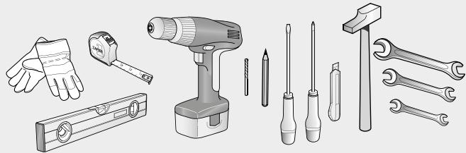
- Open the cover underneath the appliance (vertical position) or on the left (horizontal position) unscrewing the 4 screws with a cross-head screwdriver.
- Check that the thermal cut-off (see diagram 3.1 page 93) has not tripped by pressing the small round button in the centre. |
If the thermal cut-off has not tripped, carry out the following steps:
Please note, the following operations must be carried out only by a qualified professional. A multimeter must be used to measure the voltages. It is dangerous to use a tester screwdriver since it is not sufficiently reliable to check whether or not the voltage is present.
III - Measure the voltage with a multimeter at each of the following points:
| Point | Description of power connectionn | If there is no currentt |
| 1 | At the connection of the water heater to the building mains supply (wall socket output) | Problem with power supply to be corrected by an electrician |
| 2 | At the thermal safety device outlet | Thermal safety device out of service |
| 3 | On the electrical heating elements: at least one of the two elements must be powered | Electronic panel or control unit thermostat (HMI) out of service |
If the voltage is correct on all the above points, cut power, disconnect the heating elements (point 3) and measure their resistance. If the value is 0 / ohm, the resistances have failed: they need to be replaced.
| Actions to be taken | Solution | Possible cause |
| 1/ Check position of the knob on the control unit | Set the thermostat at max by turning the knob as far as possible to the right | Thermostat setting too low |
| 2/ Open one of the hot taps of the dwelling | Check the heating element of the intake tank, replace if necessary | Power supply fault on intake tank |
|
| 1/ Turn off power
2/ Drain the water heater
(See Maintenance, Article 2) | Reconnect all the connections.
(See diagrams 2.3a and 2.3b, page 91) | Connections not properly sealed |
|
| 1/ Turn off power
2/ Drain the water heater
(See Maintenance, Article 2) | Replace seal | Seal deteriorate |
|
| 1/ Turn off power
2/ Drain the water heater
(See Maintenance, Article 2) | Replace water heater | Tank corroded |
NOISE OF BOILING
| Actions to be taken | Solution | Possible cause |
| Check that the noise happens when the water heater is heating | If the noise is heard while the water heater is heating, descale it (See Maintenance, Article 2) | Water heater scaled up |
| If the noise does not happen during heating or if there are banging sounds, or if it happens when a tap is turned on call in a plumber to find the source of the problem | The water heater is not the problem |
| Reduce the thermostat setting slightly, turning the knob counter-clockwise (See Set-Up and Operations, p. 78) | Set the thermostat to the desired temperature | Thermostat set at maximum |
Call a qualified person to repair the appliance.
This electrical product complies with current safety standards It must only be repaired by qualified technicians using original spare parts. Any failure to observe this instruction may lead to serious risk for users.
2-IF THE PROBLEM PERSISTS, CHECK THE REFERENCES FOR YOUR PRODUCT
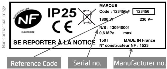
After-sales service details page 81.
1
FR INSTALLATION DU PRODUIT
FIJACION
MONTAGEM DO EQUIPAMENTO
INSTALLAZIONE DEL PRODOTTO
PL MONTAZ PRODUKTU
RO MONTAREA PRODUSULUI
EN PRODUCT MOUNTING
1.1
1.2

1.3a

1.3b

1.3a
1.4a
1.5a
1.6a
1.3b
1.4b
1.5b
1.6b
2
FR CONNEXION HYDRAULIQUE
2.1a
2.1b
2.2a
2.2b
FR
1-Cold water pipe
2-Pressure reducer recommended if pressure >0,5 MPa (5 bar)
3-Stop valve
4-Dielectric union
5-Safety relief valve
6-Funnel
7-Drain to sewage
8-Hot water tube

HEATER WITHOUT WATER
3
FR CONNECTIONÉLECTRIQUE
CONEXION ELECTRICA
LIGAÇAO ELETRICA
COLLEGAMENTO ELETTRICO
PLPODlACZENIAELEKTRYCZNE
RO CONEXIUNE ELECTRICA
EN ELECTRICAL CONNECTION
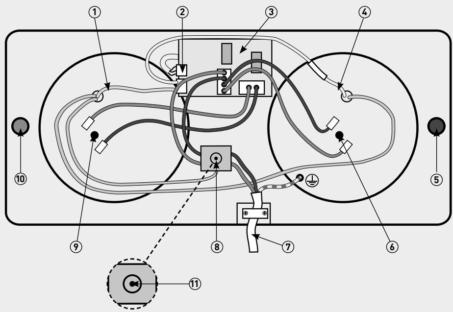
FR
1 - Probe Exit Tank (Black colour)
2-HMI Connector
3 - Electronic Board
4 - Probe Entry Tank (White Flat 30,Green Flat 50, Red Flat 80,Blue Flat 100)
5 - Cold Water [Blue ring]
6 - Heating element Entry Tank
7 - Power cable
8 - Thermal Cut Out
9 - Heating Element Exit Tant
10 - Hot Water (Red ring)
11 - Manual reset
PL
A,C.Setting knob
B. Frost Free Mode
D. Heating light indicator
IT
Only for France models