PARTY-200UHF - Pack PARTY LIGHT&SOUND - Free user manual and instructions
Find the device manual for free PARTY-200UHF PARTY LIGHT&SOUND in PDF.
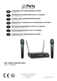
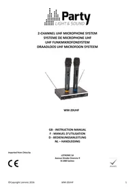
| Product type | UHF wireless microphone pack (receiver + 2 microphones) |
| Brand | PARTY LIGHT&SOUND |
| Model | PARTY-200UHF |
| Category | Wireless audio pack |
| Carrier frequency | Channel 1: 863.2 MHz / Channel 2: 864.8 MHz |
| Maximum range | 30 meters (clear line of sight) |
| Audio bandwidth | 40 Hz - 15 kHz (±3 dB) |
| Total harmonic distortion (THD) | < 0.5% |
| Signal-to-noise ratio (receiver) | > 80 dB |
| Max RF power | 8.93 dBm |
| Reception sensitivity | > 5 dBµ |
| Adjacent channel rejection | > 80 dB |
| Modulation type | F3E |
| Receiver power supply | 5 V DC / 1 A via supplied power adapter (100-240 V~, 50/60 Hz) |
| Microphone power supply | 2 LR6 (AA) 1.5 V batteries |
| Output connectors | 6.35 mm jack (unbalanced) and XLR (balanced) |
| Antennas | 2 fixed adjustable antennas |
| Indicators | Power, RF signal (A/B), audio presence, low mic battery |
| Noise reduction (squelch) | Built-in squelch circuit to reduce interference |
| Usage | Indoor only (IP not specified) |
| Operating temperature | +5 °C to +35 °C |
| Minimum safety distance | 1 meter around the receiver for ventilation |
| Certifications | CE, RED 2014/53/EU, RoHS 2011/65/EU |
| Applicable standards | ETSI EN 300 422-3, EN 55032, EN 55035, EN 62368-1 |
| Included accessories | 2 microphones, receiver, power adapter, audio cables (Jack), documentation |
Frequently Asked Questions - PARTY-200UHF PARTY LIGHT&SOUND
User questions about PARTY-200UHF PARTY LIGHT&SOUND
0 question about this device. Answer the ones you know or ask your own.
Ask a new question about this device
Download the instructions for your Pack in PDF format for free! Find your manual PARTY-200UHF - PARTY LIGHT&SOUND and take your electronic device back in hand. On this page are published all the documents necessary for the use of your device. PARTY-200UHF by PARTY LIGHT&SOUND.
USER MANUAL PARTY-200UHF PARTY LIGHT&SOUND
Accordance with the requirements of UK standards

The product is for indoor use only

To avoid hearing loss, do not expose yourself to high volume levels for long periods of time.
Correct disposal of the product

This marking indicates that this product should not be disposed with other household wastes throughout the EU. To prevent possible harm to the environment or human health from uncontrolled waste disposal, recycle it responsibly to promote the sustainable reuse of material resources. To return your used device, please use the return and collection systems or contact the retailer where the product was purchased. They can take this product for environmental safe
recycling.
IMPORTANT SAFETY INSTRUCTIONS AND WARNING
- Please read the manual carefully and keep it for future reference.
- All safety instructions and warnings must be adhered to. They are part of the manual and must be kept with the manual.
- Any warranty claims are rendered invalid if damage occurs due to non-observance of these operating an safety instructions. We assume no liability for any consequent damage.
- Unauthorized conversions and/or modifications of the product are not permitted for safety and licensing reasons (CE). The product shall be connected to a power supply only of the type described.
- To reduce the risk of fire or electrical shock, do not expose this product to rain or moisture.
- The product is approved for operation in dry, closed rooms only. Do not operate the device nearby water, such as in bathrooms or nearby swimming pools.
- Do not expose the product to extreme temperatures (< +5^ / > +35^) , strong vibrations or heavy mechanical strain during operation.
- Unplug the product from the wall socket when it is not to be used for a long time.
- Do not let foreign objects or liquids enter the housing.
- Do not remove the cover or back, as there are no user-serviceable parts inside.
- Do not place naked flame sources, such as lighted candles on the product.
- Do not use the product in a tropical climate. Only for use in moderate climates.
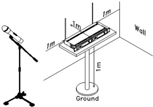
- A minimum distance of 1m around the product must be kept ensuring sufficient ventilation.
- Do not place the product on soft surfaces such as carpets or beds. Do not cover the air vents of the product. Do not obstruct the air circulation with objects such as magazines, table cloths or curtains. This prevents the dissipation of heat from the appliance and can result in overheating.
- The device complies with current European legislation regarding human exposure to electromagnetic fields.
- CONNECT DEVICE: The power outlet must be installed near the equipment and be easily accessible.
SYSTEM FEATURES
- Range: UHF series transmitters will work at a distance of up to 30m from the receiver.
- Noise squelch: Squelch circuit analyzes signal strength and quality to avoid interference due to environmental RF noise.
- Low battery warning light: The red LED on the microphone(s) flashes when the batteries must be replaced.
DUAL CHANNEL RECEIVER
FRONT PANEL
- Power Button: Power ON/OFF the receiver.
- Power Indicator: Indicate the power ON/OFF.
- Volume Knob channel 1.
- Volume knob channel 2
5 & 6."RF" signal Indicator: It glows when the Receiver receives an RF signal from mic 1 & mic2.
7 & 8."AF"Audio Level Indicator: Indicate the wireless system audio signal level of channel 1 & 2.
9 & 10. Antenna channel 1 & 2
REAR PANEL
- 5Vdc Power Jack: Connect the AC/DC adapter to receiver
- Audio Output Jack 6.35mm: Connect the audio cable from this jack to the input port of amplifier, mixer.
- XLR Balanced Output Jack: Connect the audio cable from this jack to the input port of amplifier, mixer.
MICROPHONE TRANSMITTER FEATURES
- Grille: Protects the cartridge and helps reducing the breath sounds and wind noise.
- Power & low battery indicator: Steady on when the mic is switched on and the batteries are full. Flashes when the batteries run low and need replacement.
- ON/MUTE/OFF switch: Switches the mic on or off.
TRANSMITTER BATTERY INSTALLATION
Rotate the lower part of the mic body to open the battery compartment. Insert 2x AA batteries with the correct polarity. Close the battery cover.
RECOMMENDATIONS FOR BATTERIES

This symbol indicates that used batteries should not be disposed of with household waste but deposed correctly in accordance with your local regulations..
Batteries shall not be exposed to excessive heat such as sunshine, fire or the like.
When the internal batteries are not to be used, remove them to avoid damage caused by battery leakage or corrosion.
ATTENTION: Danger of explosion if battery is incorrectly placed. Only replace by the same or equivalent type.
WARNING :Do not swallow the battery. Danger of chemical burns.Keep new and old batteries out of the reach of children.
If the battery compartment doesn't close properly, stop using the product and keep it out of the reach of children.
If you are in doubt whether the batteries have been swallowed or introduced into any other part of the body, contact immediately a doctor.
SYSTEM CONNECTION
- Receiver power connection: Connect the DC connector of the supplied AC/DC adaptor to the DC input socket on the receiver. Plug the AC connector into an appropriate mains outlet.
- Antennae: Keep the position of the antennae at an angle of 90^ .
- Audio connection: Connect the corresponding output of the receiver via a 6.35mm Jack lead to the input of a power amplifier, mixer, etc.
TIPS TO ACHIEVE MAXIMUM PERFORMANCE
- Make sure you can always see the receiver antenna from the transmitter position.
- Keep the distance from transmitter to receiver antenna as short as possible.
- Avoid placing the receiver antenna near metal surfaces and obstruction.
- Monitor battery power and replace the battery as soon as the red light goes on.
- If stacking or rack mounting receivers in a multiple system, do not allow antennae to touch or cross.
- Perform a walk-through before performance or presentation. If dead spots are found, adjust location of the receiver. If dead spots remain, mark them and avoid them during performance.
- For a good operation, don't place the receiver near to sources of interference. Place the receiver in 1m distance from the ground and let at least 1m free space around the receiver.
TROUBLESHOOTING
| Problem | Indicator status | Solution |
| No sound | Red transmitter indicator doesn’t flash | Slide the POWER ON/OFF switch on the transmitter to ON. Make sure that the batteries are properly inserted with the correct polarity (+/-). If the batteries are correctly inserted, replace them by new ones. |
| The red POWER indicator on the receiver is OFF | Check if the mains adaptor is plugged correctly into the mains outlet and the DC socket. Make sure that the mains outlet supplies the proper voltage | |
| The signal indicators A/B on the receiver are glowing | Increase the volume on the receiver. Check the output connections from the receiver to the external equipment | |
| The signal indicators A/B on the receiver are off. The POWER indicators on the transmitter and receiver are glowing | Make sure that the frequencies of the receiver and the transmitter match. | |
| Move the transmitter closer to the receiver | ||
| Distortion level increases gradually | The signal indicators A/B on the receiver and LOW BATTERY indicator on the transmitter are glowing | Replace transmitter battery |
| Bursts of noise or other audible radio signals are present | Signal indicators A/B are on | Identify potential sources of interference (other RF sources) and turn off, remove or use a wireless system operating on a different frequency |
| Momentary loss of sound as transmitter is moved around the performing area | Signal indicators A/B on the receiver are off when the sound is lost | Reposition receiver and perform walk-through test again. If audio dropouts persist, mark “dead” spots and avoid them during performance |
SYSTEM SPECIFICATIONS
RF Carrier frequency range 863.2MHz & 864.8MHz
Max. RF emission 8.93dBm
Operating range. 30m typical
Audio frequency response 40-15,000Hz ±3dB
THD. < 0.5%
RECEIVER SPECIFICATIONS
Input power. 5.0V= 1.0A via supplied mains adaptor
Signal/noise ratio . >80dB
Border upon channel rejection. >80dB
Image & spurious rejection. >80dB
Receiving sensitivity. >5dBu
MICROPHONE SPECIFICATIONS
Power requirements 2 x 1.5V= AA batteries
Modulation type F3E
INSTRUCTIONS D'UTILISATION
EXPLICATION DES SYMBOLES
Max. RF vermogen 8.93dBm
Voeding. 5.0V= 1.0A nom. via meegeleverde Lichtnet adapter
Image & spurious rejection. >80dB
Max. RF emission 8.93dBm
Alcance . tipica 30m
Banda pasante de audio 40-15000Hz ±3dB
THD. <0,5%
CHARACTERISTICAS TECNICAS DEL RECEPTOR
Max. RF emission 8.93dBm
Razdalja delovanja 30m tipicno
Max. Emissao RF 8,93dBm
EU Declaration of Conformity
Hereby we,
LOTRONIC SA
Rue F. Englert 17 Bte2
1480 TUBIZE
Belgique
+32.2.390.91.91
Certify and declare under our sole responsibility that the following product:
Trade name:
PARTY
Product name:
UHF Microphone
Type or model:
PARTY200UHF-MKII-2
Conforms to the essential requirements of the RED directive 2014/53/EU, 2011/65/EU RoHS directive and the Commission Delegated Directive (EU) 2015/863
Based on the following specifications applied:
Place and date of issue: Tubize (Belgium), on 14/08/2024
M. De Sousa
Quality manager
LOTRONIC SA
Zhaing Tubize II
Rue Franconb Angler 17 02
1480 Tubize-Belgium
T. +32(0)23909191 -info@lotronic.net
TVA:8E0887125178
CE
Ensemble Microphone UHF
Type ou modele:
PARTY200UHF-MKII-2
EN IEC 62368-1:2020+A11:2020
EN 62479 : 2010
EN 50663 : 2017
ETSI EN 301 489-1 V2.2.3 : 2019-11