USER MANUAL PARTY-200UHF V2 PARTY LIGHT&SOUND
IMPORTANT SAFETY INSTRUCTIONS AND DANGER WARNINGS
Please read the manual carefully and keep it for future reference.
All safety instructions and warnings must be adhered to. They are part of the manual and must be kept with the manual.
Any guarantee claims are rendered invalid if damage occurs due to non-observance of these operating instructions. We assume no liability for any consequent damage.
We assume no liability for personal injury or damage to property caused by incorrect handling or nonobservance of the safety instructions. Any guarantee claims expire in such cases.
Unauthorized conversions and/or modifications of the appliance are not permitted for safety and licensing reasons (CE).
The appliance is approved for operation in dry, closed rooms only. Do not operate the device nearby water, such as in bathrooms or nearby swimming pools.
The appliance may not be exposed to extreme temperatures (< +5^ / > +35^) in operation.
The appliance may not be subjected to strong vibrations or heavy mechanical strain.
Do not place any recipients filled with liquids, such as glasses or vases, on top of or directly next to the appliance. They could fall over, causing water to enter the appliance. Never pour out liquids above the appliance. Do not place any small objects, such as coins or paper clips, on the appliance since they could fall inside the appliance. You run a high risk of causing a fire or life-threatening electrocution! If any liquid or objects enter the appliance nevertheless, pull the mains plug out of the socket immediately and contact a specialist.
The appliance has been constructed according to protection class II (only for double insulated units without earth terminal).
Never place the appliance on an unstable or movable surface. Persons could be injured or the appliance damaged by it falling down.
Do not place any naked flames such as those of burning candles on or next to the appliance.
Do not place the appliance on soft surfaces such as carpets or beds. Do not cover the air vents of the appliance. Do not obstruct the air circulation with objects such as magazines, table cloths or curtains. This prevents the dissipation of heat from the appliance and can result in overheating.
- Only use the appliance in a moderate climate, not in tropical environments.
SYSTEM FEATURES
Range: UHF series transmitters will work at a distance of up to 30m from the receiver.
Noise squelch: Squelch circuit analyzes signal strength and quality to avoid interference due to environmental RF noise.
Low battery warning light: The red LED on the microphone(s) flashes when the batteries must be replaced.
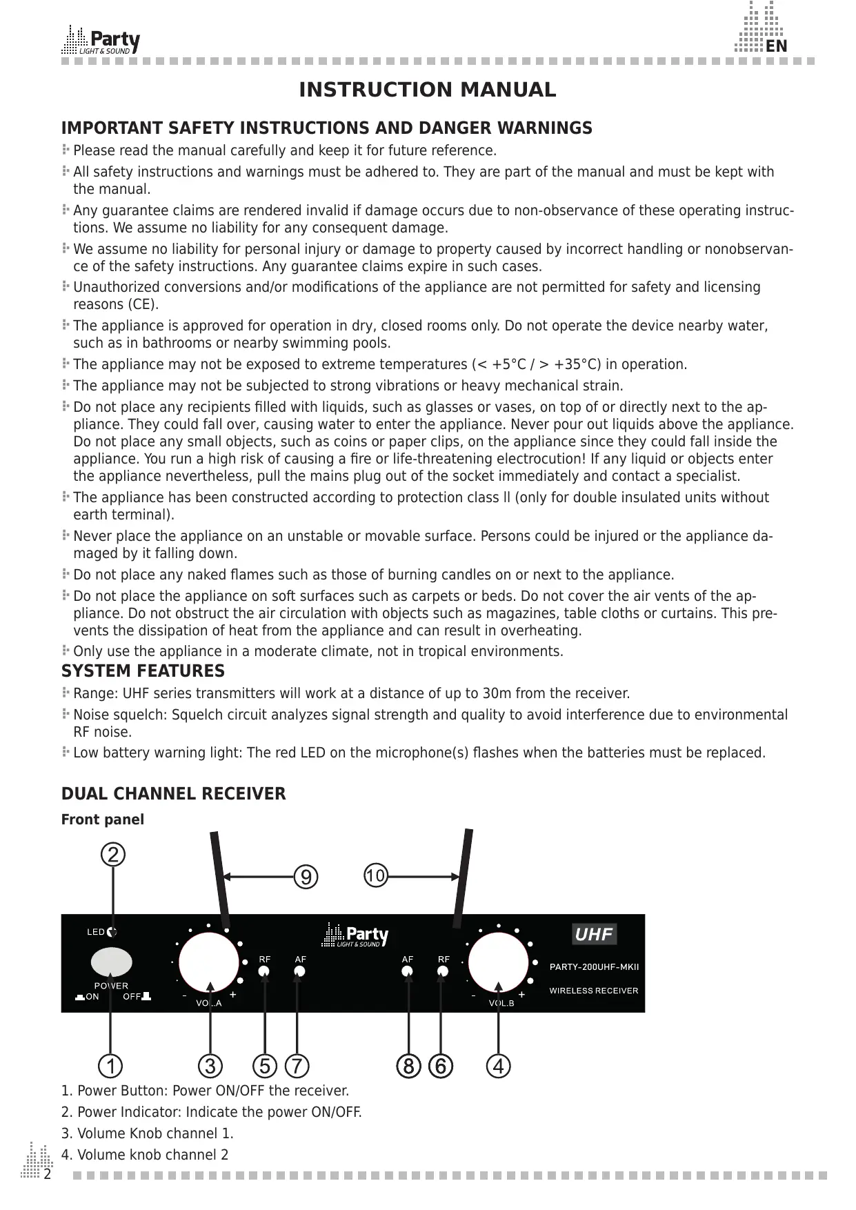
DUAL CHANNEL RECEIVER
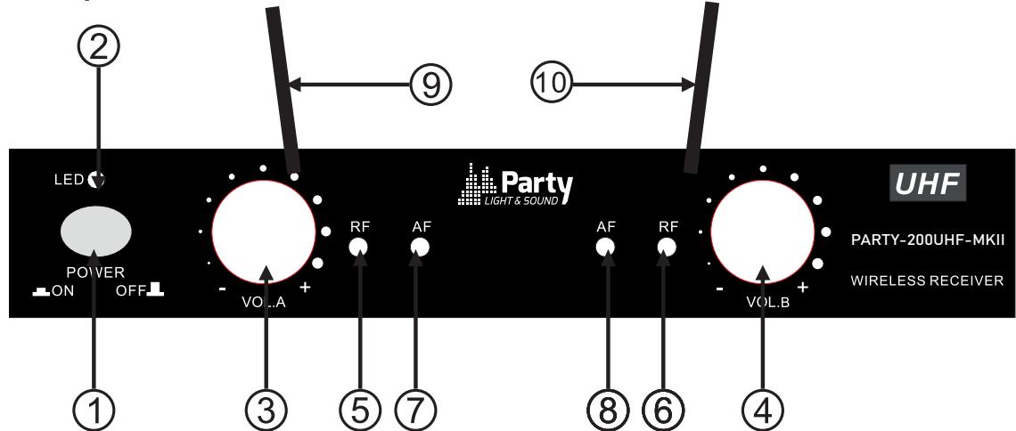
Front panel
- Power Button: Power ON/OFF the receiver.
- Power Indicator: Indicate the power ON/OFF.
- Volume Knob channel 1.
- Volume knob channel 2
5 & 6."RF" signal Indicator: It glows when the Receiver receives an RF signal from mic 1 & mic2.
7 & 8."AF"Audio Level Indicator: Indicate the wireless system audio signal level of channel 1 & 2.
9 & 10. Antenna channel 1 & 2
Rear panel

- 5Vdc Power Jack: Connect the AC/DC adapter to receiver
- Audio Output Jack 6.35mm: Connect the audio cable from this jack to the input port of amplifier, mixer.
- XLR Balanced Output Jack: Connect the audio cable from this jack to the input port of amplifier, mixer.
MICROPHONE TRANSMITTER FEATURES
- Grille: Protects the cartridge and helps reducing the breath sounds and wind noise.
- Power & low battery indicator:
Steady on when the mic is switched on and the batteries are full. Flashes
when the batteries run low and need replacement.
- ON/MUTE/OFF switch: Switches the mic on or off.
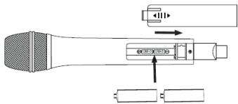
TRANSMITTER BATTERY INSTALLATION
Push the battery cover open. Insert 2x AA batteries into the battery compartment with the correct polarity. Close the battery cover.
2
RECOMMENDATIONS FOR BATTERIES

This symbol indicates that used batteries should not be disposed of with household waste but deposed correctly in accordance with your local regulations..
Batteries shall not be exposed to excessive heat such as sunshine, fire or the like.
When the internal batteries are not to be used, remove them to avoid damage caused by battery leakage or corrosion.
ATTENTION: Danger of explosion if battery is incorrectly placed.Only replace by the same or equivalent type.
WARNING : Do not swallow the battery. Danger of chemical burns. Keep new and old batteries out of the reach of children. If the battery compartment doesn't close properly, stop using the product and keep it out of the reach of children.
If you are in doubt whether the batteries have been swallowed or introduced into any other part of the body, contact immediately a doctor.
SYSTEM CONNECTION
- Receiver power connection: Connect the DC connector of the supplied AC/DC adaptor to the DC input socket on the receiver. Plug the AC connector into an appropriate mains outlet.
- Antennae: Keep the position of the antennae at an angle of 90^ .
- Audio connection: Connect the corresponding output of the receiver via a 6.35mm Jack lead to the input of a power amplifier, mixer, etc.
Make sure you can always see the receiver antenna from the transmitter position.
- Keep the distance from transmitter to receiver antenna as short as possible.
Avoid placing the receiver antenna near metal surfaces and obstruction.
Monitor battery power and replace the battery as soon as the red light goes on.
If stacking or rack mounting receivers in a multiple system, do not allow antennae to touch or cross.
Perform a walk-through before performance or presentation. If dead spots are found, adjust location of the receiver. If dead spots remain, mark them and avoid them during performance.
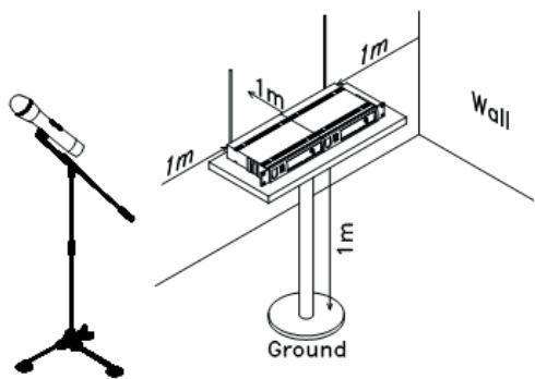
For a good operation, don't place the receiver near to sources of interference. Place the receiver in 1m distance from the ground and let at least 1m free space around the receiver.
TROUBLESHOOTING
| Problem | Indicator status | Solution |
| No sound | Red transmitter indicator doesn’t flash | Slide the POWER ON/OFF switch on the transmitter to ON. Make sure that the batteries are properly inserted with the correct polarity (+/-). If the batteries are correctly inserted, replace them by new ones. |
| The red POWER indicator on the receiver is OFF | Check if the mains adaptor is plugged correctly into the mains outlet and the DC socket. Make sure that the mains outlet supplies the proper voltage |
| The signal indicators A/B on the receiver are glowing | Increase the volume on the receiver. Check the output connections from the receiver to the external equipment |
| The signal indicators A/B on the receiver are off. The POWER indicators on the transmitter and receiver are glowing | Make sure that the frequencies of the receiver and the transmitter match. |
| Move the transmitter closer to the receiver |
| Distortion level increases gradually | The signal indicators A/B on the receiver and LOW BATTERY indicator on the transmitter are glowing | Replace transmitter battery |
| Bursts of noise or other audible radio signals are present | Signal indicators A/B are on | Identify potential sources of interference (other RF sources) and turn off, remove or use a wireless system operating on a different frequency |
| Momentary loss of sound as transmitter is moved around the performing area | Signal indicators A/B on the receiver are off when the sound is lost | Reposition receiver and perform walk-through test again. If audio dropouts persist, mark “dead” spots and avoid them during performance |
SYSTEM SPECIFICATIONS
RF Carrier frequency range 863.2MHz & 864.8MHz
Max. RF emission 7.14dBm
Operating range. 30m typical
Audio frequency response 40-15,000Hz ±3dB
THD. <0.5%
RECEIVER SPECIFICATIONS
Input power. 5V=1A via supplied mains adaptor
Signal/noise ratio . >80dB
Border upon channel rejection. >80dB
Image & spurious rejection. >80dB
Receiving sensitivity. >5dBu
MICROPHONE SPECIFICATIONS
Power requirements 2 x 1.5V= AA batteries
Modulation type F3E

Electric products must not be put into household waste. Please bring them to a recycling centre. Ask your local authorities or your dealer about the way to proceed.
INSTRUCTIONS D'UTILISATION
Voeding. 5V= 1A nom. 10W via meegeleverde Lichtnet adapter
Image & spurious rejection. >80dB
Max. RF emission 7.14dBm
Alcance .tipica 30m
Banda pasante de audio 40-15000Hz ±3dB
THD. < 0,5%
CHARACTERISTICAS TECHNICAS DEL RECEPTOR
- Interruptions ON / MUTE / OFF
Max. RF emission 7.14dBm
Razdalja delovanja 30m tipično
Hereby we, LOTRONIC SA
Avenue Zénobe Gramme, 9
1480 SAINTES
Belgique
+32.2.390.91.91
Certify and declare under our sole responsibility that the following product:
Trade name: PARTY
Product name: UHF microphone
Type or model: PARTY-UHF200-MKII
Conforms to the essential requirements of the:
RED directive 2014/53/EU, ErP directive 2009/125/EC, Commission Regulation (EC) No 278/2009, 2011/65/EU RoHS directive and the Commission Delegated Directive (EU) 2015/863
based on the following standards applied:
EN62368-1:2014+A11:2017
Draft ETSI EN301 489-1 V2.2.1 : 2019-03
Place and date of issue:
Saintes (Belgium), on 24/10/2019
Manuel De Sousa
Quality Manager

CE