WM-20UHF - Microphone PARTY LIGHT&SOUND - Free user manual and instructions
Find the device manual for free WM-20UHF PARTY LIGHT&SOUND in PDF.
| Product type | Dual UHF wireless microphone |
| Brand | PARTY LIGHT & SOUND |
| Model | WM-20UHF |
| Transmission system | UHF |
| Carrier frequency | 863.2 MHz and 864.8 MHz |
| Maximum range | 30 m |
| Audio bandwidth | 40 - 15000 Hz ±3 dB |
| Total harmonic distortion | < 0.5% |
| Receiver power supply | 220-240 V AC via mains adapter (5 V DC / 10 W) |
| Microphone power supply | 2 x 1.5 V AA batteries (LR6) |
| Audio outputs | 6.35 mm unbalanced jack and balanced XLR |
| Antennas | 2 deployable antennas at 90° |
| LED indicators | Power, RF signal per channel, audio level, low battery |
| Noise reduction | Squelch |
| Simultaneous use of multiple systems | Yes (set to different frequencies) |
| Color cap for identification | Yes |
| Windshield | Yes |
| Safety instructions | Use indoors, avoid moisture, do not block ventilation, unplug before cleaning, etc. |
| Maintenance | Unplug before cleaning, do not use liquids, clean with a dry cloth |
| Recycling | Do not dispose of with household waste, recycle at a specialized collection point |
Frequently Asked Questions - WM-20UHF PARTY LIGHT&SOUND
User questions about WM-20UHF PARTY LIGHT&SOUND
0 question about this device. Answer the ones you know or ask your own.
Ask a new question about this device
Download the instructions for your Microphone in PDF format for free! Find your manual WM-20UHF - PARTY LIGHT&SOUND and take your electronic device back in hand. On this page are published all the documents necessary for the use of your device. WM-20UHF by PARTY LIGHT&SOUND.
USER MANUAL WM-20UHF PARTY LIGHT&SOUND
Imported from China by
C E
LOTRONIC SA
Avenue Zénobe Gramme 9
B-1480 Saintes

OPERATING INSTRUCTIONS
Important Safety instructions and danger warnings
- Please read the manual carefully and keep it for future reference.
- All safety instructions and warnings must be adhered to. They are part of the manual and must be kept with the manual.
- Any guarantee claims are rendered invalid if damage occurs due to non-observation of these operating instructions. We assume no liability for any consequent damage.
- We assume no liability for personal injury or damage to property caused by incorrect handling or nonobservance of the safety instructions. Any guarantee claims expire in such cases.
- Unauthorized conversions and/or modifications of the appliance are not permitted for safety and licensing reasons (CE).
- The appliance is approved for operation in dry, closed rooms only. Do not operate the device nearby water, such as in bathrooms or nearby swimming pools.
- The appliance may not be exposed to extreme temperatures (< +5^ C / > +35^ C) in operation.
- The appliance may not be subjected to strong vibrations or heavy mechanical strain.
- Do not place any recipients filled with liquids, such as glasses or vases, on top of or directly next to the appliance. They could fall over, causing water to enter the appliance. Never pour out liquids above the appliance. Do not place any small objects, such as coins or paper clips, on the appliance since they could fall inside the appliance. You run a high risk of causing a fire or life-threatening electrocution! If any liquid or objects enter the appliance nevertheless, pull the mains plug out of the socket immediately and contact a specialist.
- The appliance has been constructed according to protection class II (only for double insulated units without earth terminal).
- Only pull the mains plug out of the socket by the intended gripping surface. Do not pull it by the cable.
- Never plug the mains plug in or out with damp or wet hands.
- Always pull the mains plug out of the mains socket:
Before cleaning the appliance
If there is a thunderstorm
If you will not be using the appliance for a long period of time ( ≥ 1 week)
- Electrical appliances must be kept out of the reach of children. Be particularly careful if children are present. Children are not aware of the hazards involved in handing electrical appliances improperly. Children could attempt to poke objects into the appliance. There is a life-threatening danger of electrocution.
- Do not leave the appliance unattended while operating it.
- Never place the appliance on an unstable or movable surface. Persons could be injured or the appliance damaged by it falling down.
- Live components can be exposed by opening covers or removing components (unless this can be done without tools). Contact points can also be live. If the appliance has to be opened in order to calibrate, service, repair or replace components or assemblies, all of its poles must be disconnected from all sources of voltage first. If the appliance has to be kept open and under voltage during maintenance or repairs, this work may only be carried out by a specialist who is familiar with the risks involved and the relevant regulations.
- Never connect the appliance directly after transferring it from a cold to a warm room. The condensation water that forms could destroy the appliance or result in an electric shock. Allow the device to reach room temperature before connecting it. Wait until the condensation water has evaporated. This can take some hours.
-
Do not place any naked flames such as those of burning candles on or next to the appliance.
-
Do not place the appliance on soft surfaces such as carpets or beds. Do not cover the air vents of the appliance. Do not obstruct the air circulation with objects such as magazines, table cloths or curtains. This prevents the dissipation of heat from the appliance and can result in overheating.
- Only use the appliance in a moderate climate, not in tropical environments.
- Defective mains cables may only be replaced by specialists. Danger of shock hazard!
- If you are not sure about the correct connection or if questions arise which are not answered by the operating instructions, please do not hesitate to contact support or a specialist of your choice. Consult a specialist if you are in doubt the operating principle or the safety of the product.
SYSTEM FEATURES
- Multiple system use: Several UHF systems can be used in the same performance space. Each system must be set to a different frequency (frequency marked on the back of the receiver).
- Simultaneous output use: Unbalanced 6.35mm jack plug and balanced XLR output connectors may be used simultaneously to different external devices.
- Range: UHF series transmitters will work at a distance of up to 30m from the receiver.
- Noise squelch: Squelch circuit analyzes signal strength and quality to avoid interference due to environmental RF noise.
- Low battery warning light: A red light on the microphone(s) warns the user that there is less than one hour of battery life left.
DUAL CHANNEL RECEIVER
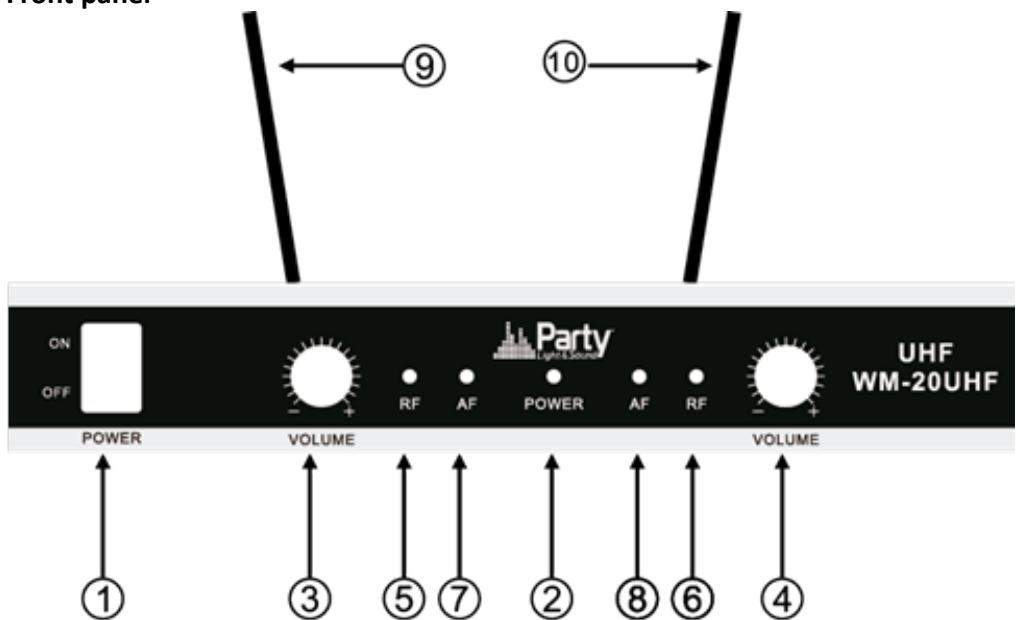
Front panel

- Power Button: Power ON/OFF the receiver.
- Power Indicator: Indicate the power ON/OFF.
- Volume Knob channel 1.
- Volume knob channel 2
5 & 6."RF" signal Indicator: It glows when the Receiver receives an RF signal from mic 1 & mic2.
7 & 8."AF"Audio Level Indicator: Indicate the wireless system audio signal level of channel 1 & 2.
9 & 10. Antenna channel 1 & 2
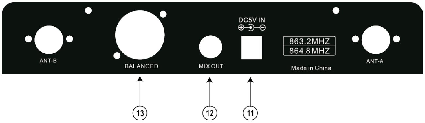
Rear panel.
- 5Vdc Power Jack: Connect the AC/DC adapter to receiver
- Audio Output Jack 6.35mm: Connect the audio cable from this jack to the input port of amplifier, mixer.
- XLR Balanced Output Jack: Connect the audio cable from this jack to the input port of amplifier, mixer.
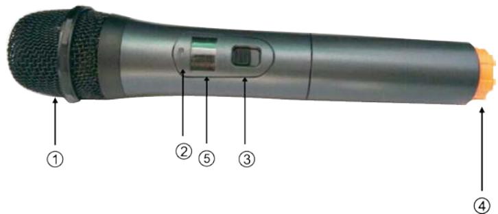
MICROPHONE TRANSMITTER FEATURES
- Grille: Protects the cartridge and helps reducing the breath sounds and wind noise.
- Power indicator
- ON/OFF switch
- Tail-hood to identify the mic
- Display showing the frequency
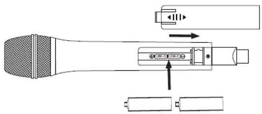
TRANSMITTER BATTERY INSTALLATION
Push the battery cover open. Insert 2x AA batteries into the battery compartment with the correct polarity. Close the battery cover.
SYSTEM CONNECTION
- Receiver power connection: Connect the DC connector of the supplied AC/DC adaptor to the DC input socket on the receiver. Plug the AC connector into an appropriate mains outlet.
- Antenna: Keep the position of the antenna at an angle of 90^ .
- Audio connection: Connect the corresponding output of the receiver via a 6.35mm Jack lead or an XLR lead to the input of a power amplifier, mixer, etc.
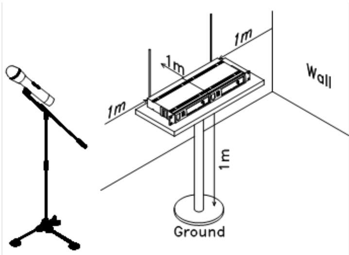
TIPS TO ACHIEVE MAXIMUM PERFORMANCE
Make sure you can always see the receiver antenna from the transmitter position.
Keep the distance from transmitter to receiver antenna as short as possible.
Avoid placing the receiver antennae near metal surfaces and obstruction.
Monitor battery power and replace the battery as soon as the red light goes on.
If stacking or rack mounting receivers in a multiple system, do not allow antennae to touch or cross.
Perform a walk-through before performance or presentation. If dead spots are found, adjust location of the receiver. If dead spots remain, mark them and avoid them during performance.
For a good operation, don't place the receiver near to sources of interference. Place the receiver in 1m distance from the ground and let at least 1m free space around the receiver.
TROUBLESHOOTING
| Problem | Indicator status | Solution |
| No sound | Red transmitter indicator doesn’t flash | Slide the POWER ON/OFF switch on the transmitter to ON. Make sure that the batteries are properly inserted with the correct polarity (+/-). If the batteries are correctly inserted, replace them by new ones. |
| No sound | The red POWER indicator on the receiver is OFF | Check if the mains adaptor is plugged correctly into the mains outlet and the DC socket. Make sure that the mains outlet supplies the proper voltage |
| No sound | The signal indicators A/B on the receiver are glowing | Increase the volume on the receiver. Check the output connections from the receiver to the external equipment |
| No sound | The signal indicators A/B on the receiver are off. The POWER indicators on the transmitter and receiver are glowing | Make sure that the frequencies of the receiver and the transmitter match. Move the transmitter closer to the receiver |
| Distortion level increases gradually | The signal indicators A/B on the receiver and LOW BATTERY indicator on the transmitter are glowing | Replace transmitter battery |
| Bursts of noise or other audible radio signals are present | Signal indicators A/B are on | Identify potential sources of interference (other RF sources) and turn off, remove or use a wireless system operating on a different frequency |
| Momentary loss of sound as transmitter is moved around the performing area | Signal indicators A/B on the receiver are off when the sound is lost | Reposition receiver and perform walk-through test again. If audio dropouts persist, mark “dead” spots and avid them during performance |
SYSTEM SPECIFICATIONS
RF Carrier frequency range . 863.2MHz & 864.8MHzMHz
Operating range 30m typical
Audio frequency response 40-15,000Hz ±3dB
THD. <0.5%
RECEIVER SPECIFICATIONS
Input power. 5Vdc via supplied mains adaptor
Signal/noise ratio .>80dB
Border upon channel rejection .>80dB
Image & spurious rejection. >80dB
Receiving sensitivity. >5dBu
MICROPHONE SPECIFICATIONS
Power requirements . 2 x 1.5AA batteries
Modulation type F3E
RF output. >10dBm
Max. deviation ±25kHz

Electric products must not be put into household waste. Please bring them to a recycling centre. Ask your local authorities or your dealer about the way to proceed.
INSTRUCTIONS D'UTILISATION
ONTVANGER
Front panel
Lichtnet adapter 5Vdc nom. 10W
Image & spurious rejection. >80dB
Spurious emission .<40dB
EC Declaration of Conformity
We, LOTRONIC SA
Avenue Zénobe Gramme, 9
1480 SAINTES
Belgique
+32.2.390.91.91
certify and declare under our sole responsibility that the following product:
Trade name: PARTY LIGHT & SOUND
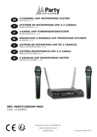
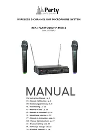
Product name: DUAL WIRELESS SYSTEM WITH 2 UHF HANDS MICROPHONES
Type or model: WM-20UHF
conforms with the essential requirements of:
RTTE directive 1999/5/EC - LVD directive 2014/35/EU
based on the following standards applied:
EN60065:2014
EN62479 :2010
EN 301 489-1 V1.9.2
EN 301 489-9 V1.4.1
EN 301 357-1 V1.4.1
EN 301 357-2 V1.4.1
Place and date of issue: Saintes (Belgium), on 09/09/2016
Guive Akbar
Technical manager
CEO
Responsible technique
LOTRONIC SA
Av. Zenobe Gramme 9
1480 Saintes - Belgium
Tel. +32.2.390.91.91
Fax +32.2.390.93.19
info@lotronic.net
www.lotronic.com