XDOM PMML - Remote control EDOBE - Free user manual and instructions
Find the device manual for free XDOM PMML EDOBE in PDF.
| Product Type | Wireless remote for lighting (micro-transmitter/receiver pack) |
| Brand | EDOBE |
| Model | XDOM PMML |
| Category | Remote control |
| Included components | 1 micro-transmitter EMML, 1 micro-receiver RMML |
| Transmitter power supply | Battery (type not specified, to be checked) |
| Receiver power supply | 230 V AC via phase and neutral (mains) |
| Max. luminaire power | Not specified (connect a single luminaire, no multi-sockets) |
| Radio frequency | Not specified (ebode domestic range) |
| Range | Approximately 30 meters in open field (estimate) |
| Main functions | Wireless on/off, creation of two-way switches, addition of remote controls |
| Programming | House code (A-P) and unit code (1-16) via transmitter buttons |
| Light indicators | Transmitter: red LED (off) and green LED (on); receiver: green/orange LED |
| Installation | Flush mount in wall (hole Ø65mm, depth 40mm for transmitter) |
| Compatibility | Entire ebode radio domestic range |
| Maintenance and cleaning | Clean with a soft, dry cloth; do not use abrasive products |
| Safety | Cut power before installation; do not open; use according to instructions |
| Spare parts and repairability | No user-serviceable parts; contact authorized after-sales service |
Frequently Asked Questions - XDOM PMML EDOBE
User questions about XDOM PMML EDOBE
0 question about this device. Answer the ones you know or ask your own.
Ask a new question about this device
Download the instructions for your Remote control in PDF format for free! Find your manual XDOM PMML - EDOBE and take your electronic device back in hand. On this page are published all the documents necessary for the use of your device. XDOM PMML by EDOBE.
USER MANUAL XDOM PMML EDOBE
Transmitter & Receiver Remote Controlled Appliance Kit
User guide 6
Bedienungsanleitung 10
Gebruiksaanwijzing 14
Anvandermanual 18
Guideutilisateur 22
Guia del uso 26
Manual do'utilizar 30
Manuale per l'utente 34

General Security Note
For carefree and safe use of this product, please read this manual and safety information carefully and follow the instructions. Technical manipulation of the product or any changes to the product are forbidden, due to security and approval issues.
Please take care to set up the device correctly - consult your user guide. WARNING: Do Not Open! Risk of Electrical Shock. Voltages in this equipment are hazardous to life. No user-serviceable parts inside. Refer all servicing to qualified service personnel.
Important: the product must be used according the instructions in this manual and is not suitable for other purposes.
Please avoid the following: strong mechanical wear and tear, high temperature, strong vibrations, and high humidity.
Please also respect the additional security notes in the various user guide chapters. To ensure correct set up please read the manual and security notes carefully.

The MICRO MODULE PACK allows the installation of a wireless controller for incandescent, halogen, low-voltage, energy-saving or LED light fixtures.
- Without the need to run wires, the Micro-Module Pack allows you to place a switch where you choose.
- It integrates with existing switches eliminating the need of running new wires or cutting extra holes in the wall.
- It installs in just minutes.
- It's compatible with all ebode home automation devices. For more information, visit the site www.ebodeelectronics.eu.
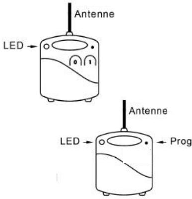
DESCRIPTION
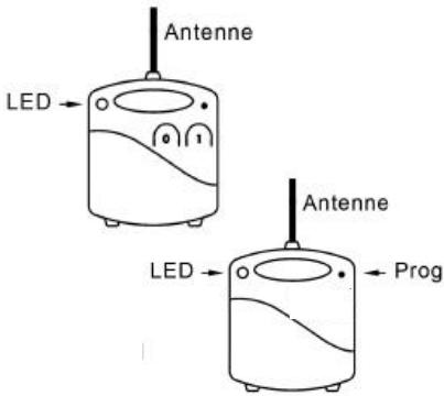
1.1 EMML Wireless Micro Transmitter LED indicator
(1) For switching on/programming
(0) For switching off/programming
1.2 RMML Micro-Receiver
LED indicator
(PROG) for programming or (RESET)

INSTALLATION
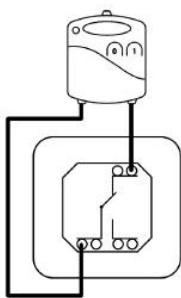
2.1 EMML INSTALLATION OF THE MICRO TRANSMITTER

- Cut out a 65~mm hole 40~mm deep with a hole saw.
- Set the insert box in the wall.
- Remove the battery's protective tab then press the buttons to test. Pressing the (0) lights the red panel light. Pressing the (1) lights the green panel light.
- Connect the Micro Transmitter's wires to the switch (see opposite diagram)
- Place the Micro Transmitter and the switch in the insert box taking care to pull out the antenna as much as you can.
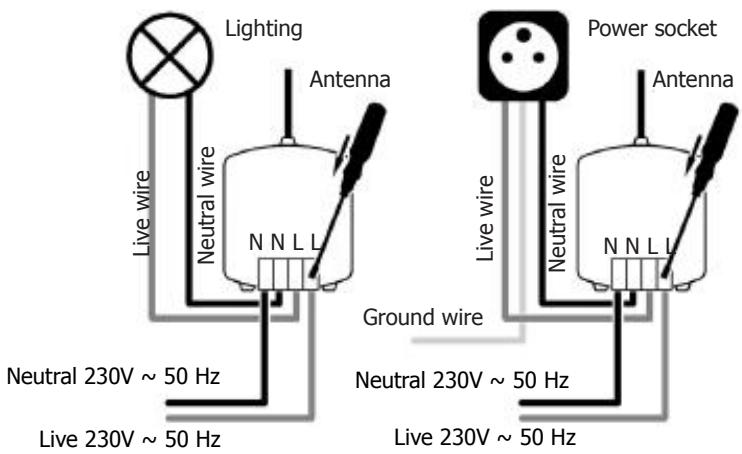
2.2 RMML INSTALLATION OF THE MICRO RECEIVER RMML
The Micro Receiver can be connected either directly to the light fixture (overhead light, wall lamp, etc.) or behind a power socket.
CAUTION
-
The LIVE and the NEUTRAL wires are essential.
-
For a remote-controlled socket verify the thickness of the back of the socket, add 25mm in order to define the minimum depth of the wall box.
Do not connect more lights as the total permitted amount of wattage allows.
1. CAUTION: Shut off power to the circuit in the electrical panel.
- Press on the top of the terminal board with a screwdriver and insert the wires (for a light fixture see diagram 1, for a power socket see diagram 2).
Then verify the connections by pulling lightly on the wires. - Pull out the antenna as far as you can for better reception.
ACTIVATION
Once the Micro-Modules have been installed connect the circuit switch.
Verify proper operation by pressing the switch's On/Off button. The installation is done!

UPGRADING AND PROGRAMMING
If you wish to add other Micro Transmitters, Micro Receivers or remote control switches to the existing installation, you may choose among the following solutions:
-Add one or many command points to create a two-way switch: Install the Micro Transmitter(s) as specified in its manual
-Add a remote control switch: The first line of buttons automatically controls the lighting. (See remote control switch manual).
-Add an additional lighting spot: Install the Micro Receiver as specified in its manual.
REMARKS
Within a single installation, no additional programming is necessary to add one or more Micro Module(s) and remote control switch(es) to this pack.
-Installing an additional pack for another lighting point: In order to separate the two installations, follow these instructions.
3.1 HOW TO PROGRAM THE MICRO TRANSMITTER
In order to add the Micro Transmitter to a different installation from the original one, or to one with interference from a nearby system, it is necessary to program a different code.
The programming address is made up of a "HOUSE" code (from A through P) and of a "UNIT" code (from 1 through 16). The factory default address of the transmitter/receiver pair is set at A1. Proceed as follows to set a different code.
A. Accessing programming mode.
- Press the Micro Transmitter's START (1) and STOP (0) buttons briefly and simultaneously. The LED turns YELLOW.
Then the LED lights up RED once (for the HOUSE CODE), then GREEN once (for the UNIT code). The Micro Transmitter is in the A-1 setting.
You have 6 seconds to program a new code.
B. Setting the HOUSE CODE.
- Press the (1) button as many times as needed to get to the desired HOUSE CODE and then release it.
Example: A = press once, B = press twice, C = press three times, ... P = press 16 times.
- After having set the HOUSE CODE, the LED will flash YELLOW 3 times to confirm the code has been memorized and exit from programming mode.
C. Set the UNIT CODE.
-
Repeat step A only.
-
Press the (0) button as many times as needed to get to the desired UNIT CODE and then release it.
Example: 1 = press once, 2 = press twice, 3 = press 3 times... 16 = press 16 times.
After having set the UNIT code, the LED will flash YELLOW 3 times.
3.2 HOW TO PROGRAM THE MICRO RECEIVER
The Micro Transmitter commands must be recognized in order to add the Micro Receiver to a different installation from the original or to one with interference from a nearby system.
- Install the Micro Receiver (Paragraph 3)
- Proceed to make a "Reset". Press down and hold the button in the (PROG) opening with a paper clip until the LED lights up GREEN, then release it.: the LED should flash YELLOW: the Micro Receiver now has no code.
- With the paper clip, press down briefly in the (PROG) opening. The LED will flash GREEN and wait for a command from a Micro Transmitter or remote control switch.
- Press one of the buttons on the Micro Transmitter or the remote control switch: the Micro Receiver LED will stop blinking, confirming it has received the command. The programming is done!
REMARKS
The RMML Micro Receiver will remember as many Micro-Transmitters and remote control switches as necessary.

VERIFICATION
VerifyOn/Off switch operation.
You must wait about a second between each On / Off command.
When changing the battery, the registered code will be retained by the Micro Transmitter.
Troubleshooting - please check FAQ and technical support on
www.ebodeelectronics.eu

EINFUHRUNG
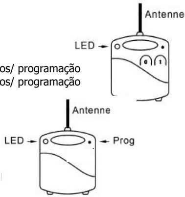
1.1 EMML microzender LED indicator
1.2 RMML Micro Receptor
Indicator LED
(PROG) para programar o (REINICIO)

INSTALACION
2.1 EMML INSTALLACION DEL MICRO TRANSMISOR
1.1 EMML Micro Transmitter
Indicator LED
(1) Paraactivationremota deequipamentos/programacao
(0) Paraactivationremota deequipamentos/programacao
1.2 RMML Micro Receptor
Indicator LED
(PROG) para programar ou reset

Instalacao
2.1 EMML Micro Transmitter