
XDOM VL58 - Wireless audio/video transmitter EDOBE - Free user manual and instructions
Find the device manual for free XDOM VL58 EDOBE in PDF.
| Product Type | Wireless Audio/Video Transmitter |
| Brand | EDOBE |
| Model | XDOM VL58 |
| Manufacturer | EDOBE |
| Operating Frequency | 5.8 GHz |
| Range in Open Space | Up to 100 m |
| Range Through Walls | Up to 30 m |
| Number of Channels | 4 (A, B, C, D) |
| Transmitter Power Supply | 7.2 V DC, 320 mA (power adapter included) |
| Receiver Power Supply | 7.2 V DC, 250 mA (power adapter included) |
| Transmitter Dimensions (with antenna) | 140 × 100 × 140 mm |
| Receiver Dimensions (with antenna) | 92 × 58 × 20 mm |
| Transmitter Connectivity | 2 A/V inputs (RCA and Mini-DIN), 1 A/V output (Mini-DIN), coaxial UHF/RF output, IR extender input |
| Receiver Connectivity | 1 A/V output (Mini-DIN), IR antenna, source selector |
| Supported Signal Types | Composite video, analog stereo audio |
| Main Features | Wireless A/V transmission, IR extender for remote control, remote source selection |
| Kit Includes | Transmitter, receiver, RCA cables, SCART adapters, Mini-DIN/RCA cables, jack/RCA cable, coaxial UHF cable, 3-LED IR extender, power adapters, manual |
| Safety | Indoor use only, do not expose to moisture, do not open, use only the supplied adapters |
| Maintenance | Clean with a dry, soft cloth, do not use liquids |
| WiFi Compatibility | No interference as it uses the 5.8 GHz band (different from 2.4 GHz WiFi) |
| Repairability | No user-serviceable parts, contact a qualified technician |
Frequently Asked Questions - XDOM VL58 EDOBE
User questions about XDOM VL58 EDOBE
0 question about this device. Answer the ones you know or ask your own.
Ask a new question about this device
Download the instructions for your Wireless audio/video transmitter in PDF format for free! Find your manual XDOM VL58 - EDOBE and take your electronic device back in hand. On this page are published all the documents necessary for the use of your device. XDOM VL58 by EDOBE.
USER MANUAL XDOM VL58 EDOBE
A/V Sender – Now on 5.8 GHZ frequency!
VL58
User guide 9
Bedienungsanleitung 15
Gebruiksaanwijzing 21
Anvandermanual 27
Guideutilisateur 33
Guía del usuario 39
Manual do utiliser 45
Manuale per l'utente 51
Brukerhandbok 57
Käytöohje 63
Contents of the kit / Lieferumfang / Inhoud van de set / Innehäll / Contenu du kit / Contenido del paquete / Conteúdo do kit / Dotazione del kit / Innhold I Pakken / Paketin Sisalto
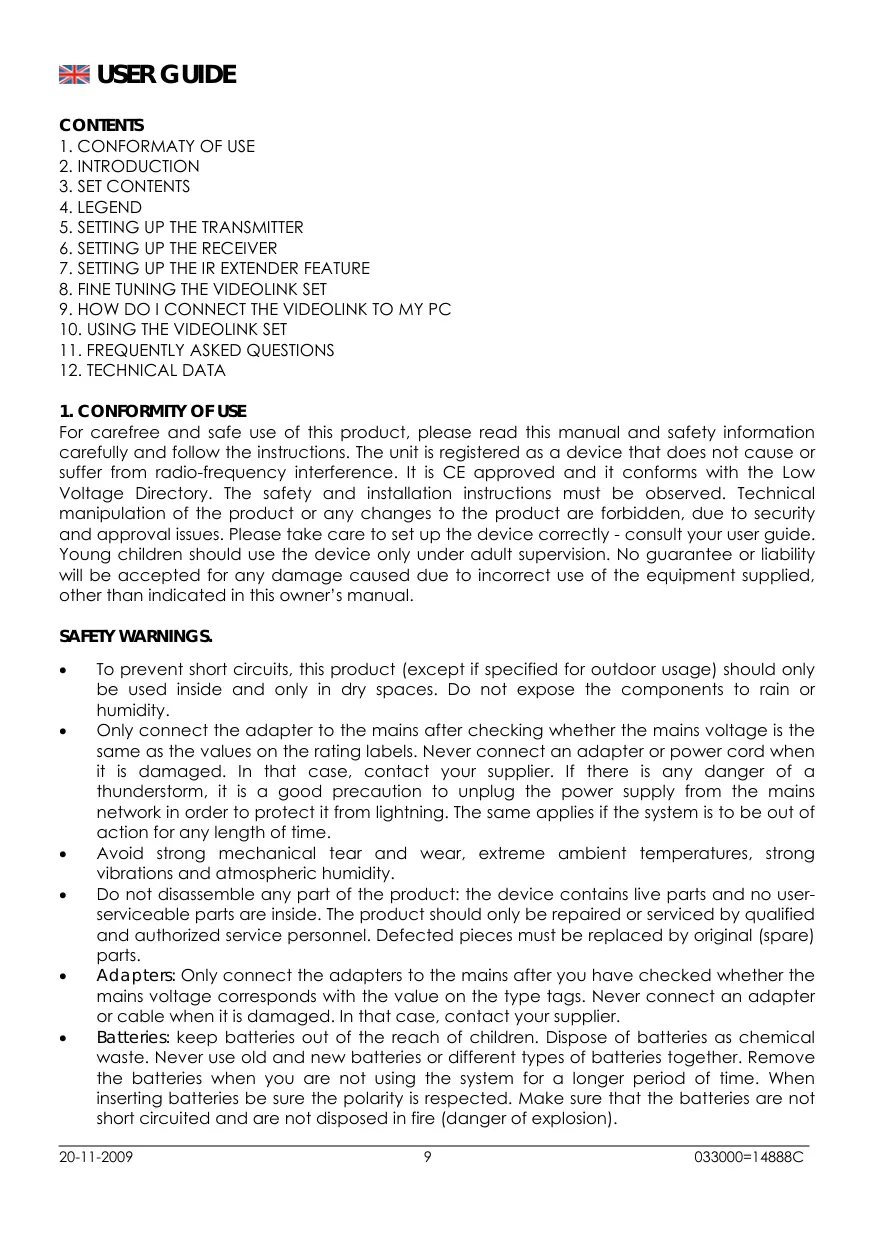
1x Transmitter VT58
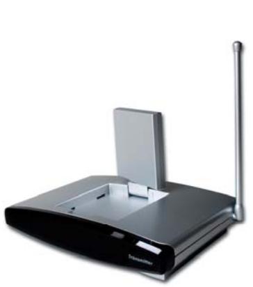
1x Receiver VR58
Set of accessories:
4x RCA Phono to SCART Adapter
1x RCA Phono Cable
3x Mini DIN to RCA Phono Cable
1x UHF Coaxial IEC Cable
1x 3.5mm Stereo to RCA Phono Adapter
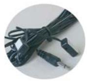
1x IR Extender Cable for 3 Devices
2x 230V/50Hz Power Supply Adapter
Pictures / Figures
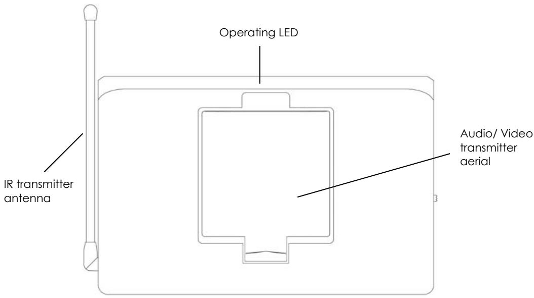
Figure 1. Topview VL58 Transmitter
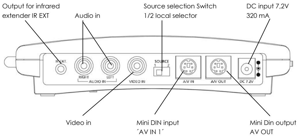
Figure 2. Rear side view VL58 Transmitter
Figuur 3. Bottom view VL58 transmitter
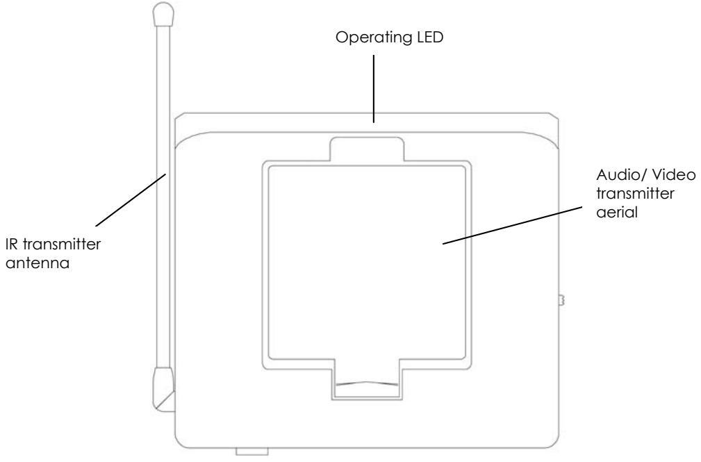
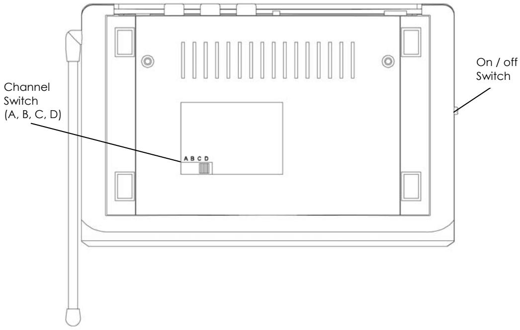
Figure 4. Topview VL58 Receiver
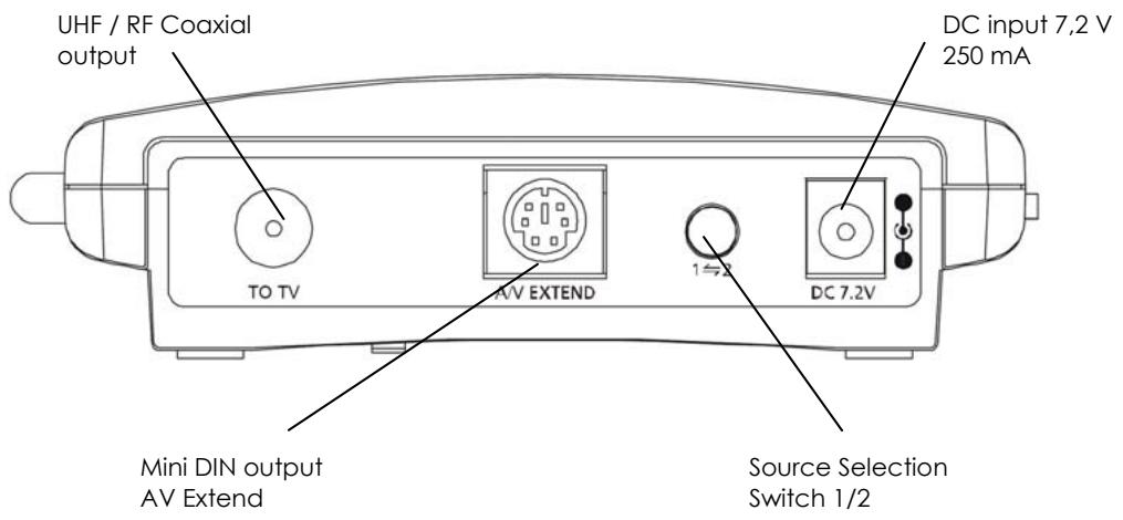
Figure 5. Back side view VL58 Receiver
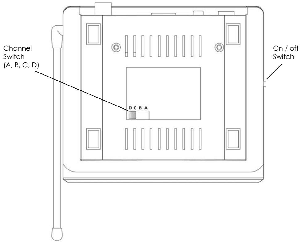
Figure 6. Bottom view VL58 Receiver
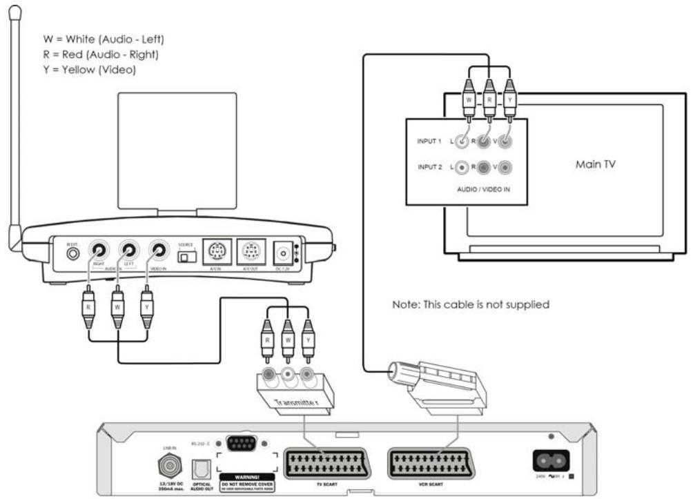
Figure 7
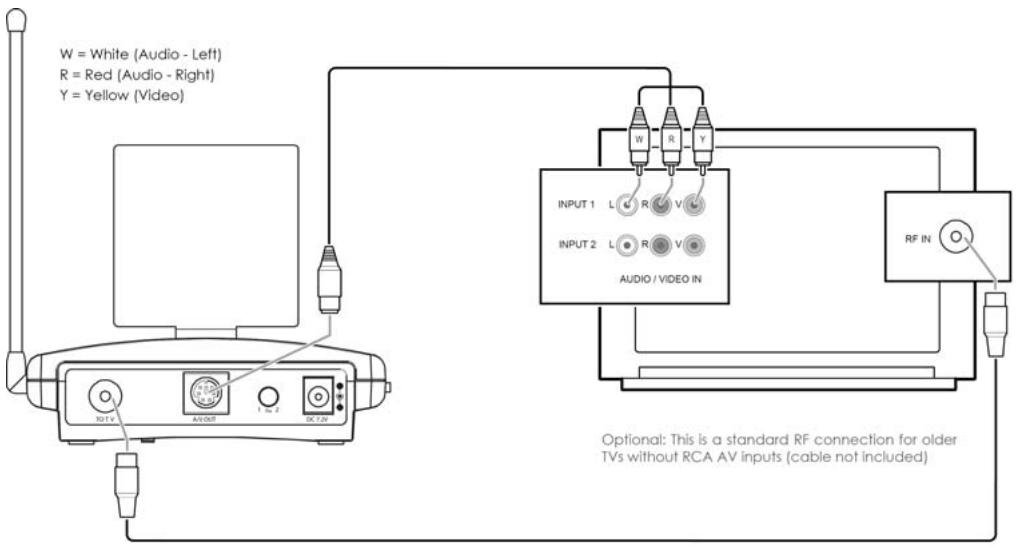
Figure 8
CONTENTS
- CONFORMATY OF USE
- INTRODUCTION
- SET CONTENTS
- LEGEND
- SETTING UP THE TRANSMITTER
- SETTING UP THE RECEIVER
- SETTING UP THE IR EXTENDER FEATURE
- FINE TUNING THE VideOLINK SET
- HOW DO I CONNECT THE VideOLINK TO MY PC
- USING THE VIDEOLINK SET
- FREQUENTLY ASKED QUESTIONS
- TECHNICAL DATA
1. CONFORMITY OF USE
For carefree and safe use of this product, please read this manual and safety information carefully and follow the instructions. The unit is registered as a device that does not cause or suffer from radio-frequency interference. It is CE approved and it conforms with the Low Voltage Directory. The safety and installation instructions must be observed. Technical manipulation of the product or any changes to the product are forbidden, due to security and approval issues. Please take care to set up the device correctly - consult your user guide. Young children should use the device only under adult supervision. No guarantee or liability will be accepted for any damage caused due to incorrect use of the equipment supplied, other than indicated in this owner's manual.
SAFETYWARNINGS.
- To prevent short circuits, this product (except if specified for outdoor usage) should only be used inside and only in dry spaces. Do not expose the components to rain or humidity.
- Only connect the adapter to the mains after checking whether the mains voltage is the same as the values on the rating labels. Never connect an adapter or power cord when it is damaged. In that case, contact your supplier. If there is any danger of a thunderstorm, it is a good precaution to unplug the power supply from the mains network in order to protect it from lightning. The same applies if the system is to be out of action for any length of time.
- Avoid strong mechanical tear and wear, extreme ambient temperatures, strong vibrations and atmospheric humidity.
- Do not disassemble any part of the product: the device contains live parts and no user-serviceable parts are inside. The product should only be repaired or serviced by qualified and authorized service personnel. Defected pieces must be replaced by original (spare) parts.
- Adapters: Only connect the adapters to the mains after you have checked whether the mains voltage corresponds with the value on the type tags. Never connect an adapter or cable when it is damaged. In that case, contact your supplier.
- Batteries: keep batteries out of the reach of children. Dispose of batteries as chemical waste. Never use old and new batteries or different types of batteries together. Remove the batteries when you are not using the system for a longer period of time. When inserting batteries be sure the polarity is respected. Make sure that the batteries are not short circuited and are not disposed in fire (danger of explosion).
In case of improper usage or if you have opened, altered and repaired the product yourself, all guarantees expire. The supplier does not accept responsibility in the case of improper usage of the product or when the product is used for purposes other than specified. The supplier does not accept responsibility for additional damage other than covered by the legal product responsibility.
2. INTRODUCTION
The VideoLink ADVANCED enables you to transmit a video signal from your VCR, Satellite receiver, Cable box, DVD-player, DVD-recorder, Satellite receiver, set top box, PC etc. to a (second) TV without running wires. The transmitter sends an Audio/Video signal from 2 different sources to the receiver via 5.8GHz radio frequency signals. The receiver converts the radio signal back into an A/V signal. The receiver also converts the infrared signals sent by the remote control of the A/V source into radio frequency signals. The transmitter will then reconvert these signals into infrared signals in order to control the connected A/V devices. Using the 5.8GHz frequency, you will normally have no problems with distortion from wireless (WiFi) networks, Cordless phones and microwave for example.
3. SET CONTENTS.
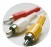
1 Transmitter 1 RCA cable (white / red / yellow)
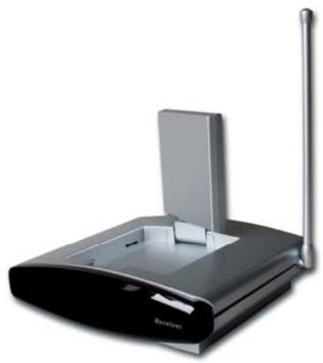
1 Receiver 2 SCART adapters (labelled Transmitter).
2 Power Supply adapters 1 SCART adapter (labelled Receiver)
1 IR Extender cable with 3 LEDs. 1 SCART adapter (labelled AV OUT).
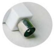
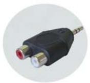
1 3,5 mm jackplug / RCA adapter (audio) 1 UHF Coaxial cable
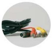
3 Mini-DIN / RCA cables (white / red / yellow).1 User manual
4.LEGEND:
(Pictures on page 4-6)
| Transmitter | Receiver |
| Mini DIN input 'AV IN 1' | Mini DIN output AV EXTEND |
| Mini DIN input 'AV IN 2' | UHF/RF Coaxial output |
| DC input 7,2V 320 mA | DC input 7,2V 250mA |
| Mini DIN output AV OUT | Audio/Video receiver aerial |
| Source selection Switch 1/2 (LOCAL SELECTOR) | IR transmitter antenna |
| Output for infrared extender IR EXT. | Operating LED / infrared receiver |
| Audio/Video transmitter aerial | Source selection Switch 1/2 |
| IR transmitter antenna | ON/OFF switch |
| Operating LED | Channel switch A/B/C/D |
| On/OFF switch | |
| Channel switch A/B/C/D |
5. SETTING UP THE TRANSMITTER
See figure 7 on page 7.
The transmitter can be connected to two A/V devices and a local television set.
-
Connect the RCA/RCA cable to the 'A/V IN 1' or the Mini-DIN/RCA cable on the 'A/V IN 2' of the transmitter.
-
Connect the RCA plugs of this cable to the A/V device you want to transmit the signal from. Make sure the colours of the plugs and the input connectors match. If the A/V device is equipped with a SCART connector you can also connect the transmitter using the SCART adapter labelled 'TRANSMITTER'.
- In order to also connect the A/V device to 'TV1' (your local TV), insert a Mini -DIN/RCA cable between the 'AV OUT' of the transmitter and your 'TV1'. If this TV is equipped with a SCART connector you can also connect the transmitter using the included SCART adapter labelled 'AV OUT'.
- Set to channel selector (A-B-C-D) to A.
- Insert the plug of one of the power adapters in the 'DC in' on the back of the transmitter and plug the power adapter included into a wall socket (230V-50Hz). Only use the adapter provided!
- Turn the On/Off switch to 'ON'.
- Place the transmitter in an easy accessible spot with enough space around it. Aim the inside of the dish antenna at the location of the receiver.
- Put the side antenna in an upright position.
- When you want to connect a second A/V device, please repeat steps 1 to 3, and then turn the On/Off switch to 'ON' again.
Video signal and S-VIDEO signal
It is not possible to connect a A/V device via S-VIDEO. When you have a A/V device which only has S-VIDEO output, (a S-VIDEO connection is a small round mini DIN plug with 4 pins) you can use a S-VIDEO to Composite video adapter (product code: SVHS-CV).
6. SETTING UP THE RECEIVER.
See figure 8 on page 7.
- Connect the Mini-DIN/RCA cable to the outputs at the back of the receiver.
- Plug the other end of this cable into the A/V input of TV2. Make sure the colours of the plugs and the input connectors match. If the TV is equipped with a SCART connector then you can also connect the transmitter using the included SCART adapter labelled 'RECEIVER'. When your TV does not have a SCART connection, you can also connect the receiver to your TV via an antenna cable. To do this, connect the VIDEOLINK to your TV via the RF output and set the TV to channel 36.
- Insert the power adapter plug into the DC input on the back of the receiver and plug the power adapter into a wall socket (230V-50Hz). Only use the adapter provided!
- Turn the On/Off switch to 'ON'.
- Set the channel selector (A-B-C-D) to A.
- Place the receiver in an easy accessible spot with enough space around it, e.g. on top of the TV. Point the inside of the dish antenna at the location of the transmitter.
- Put the side antenna in an upright position.
7. SETTING UP THE IR EXTENDER FEATURE.
See figure 7 on page 7.
- Connect the IR Extender included to the input at the back of the transmitter.
- Remove the protective label of one of the IR emitters. Place this IR emitter on the IR window of the A/V device you want to control. Fix the emitter very lightly. Before fixing the IR emitter firmly you are advised to check if the extender works properly. Therefore point your own remote at the window on the front of the receiver and press some of the channel choose buttons. If the channel does not change, the IR emitter may not be fixed in the right position.
The position is sometimes critical. Repeat this procedure when fixing the 2nd IR emitter to the other A/V device connected.
- You can use the third IR to control a third A/V device. If you are not using this IR emitter, do not remove it!
8. FINE TUNING THE VIDEOLINK SET.
Make sure your A/V equipment is switched on.
When the receiver on your TV is connected with RCA plugs and/or a SCART adapter:
Switch the TV, to which you have connected the receiver, over to the TV channel, which belongs to the A/V input, on which you have connected the receiver. In case of most appliances, you do that by pressing the 0 or A/V button. You will now have an image directly. The TV will never have to look for channels for the connection via 'A/V IN'.
When the receiver on your TV is connected to the RF output:
Switch the TV, to which you have connected the receiver, over to TV channel 36. The wireless VIDEOLINK usually works best with the flat faces of the antennas on the Transmitter and Receiver unit look at one another. Sometimes however distance, reflections and other effects in the home may affect the signal so that some adjustment of either Transmitter or Receiver antenna may be necessary to get the best signal. If still experiencing difficulty, try changing the "ABCD" channel selector and change channels. Remember though both the receiver and transmitter must be on the same channel. The maximum distance between transmitter and receiver depends on local environmental conditions, but on average the distance is up to 30m , through walls and floors.
9. HOW TO CONNECT THE VIDEOLINK TO A PC.
The VIDEOLINK has to be connected to the 'TV-out' or 'Video-out' of a PC. The connection can usually be found on the graphics card. The signal needs to be a so-called 'composite video signal'. This is also called 'CVBS'. Connecting to a PC can be done with RCA/RCA on A/V1 as well as RCA/mini-DIN on A/V2.
The connector of your graphics card will most likely look as follows:
Yellow RCA connector (RCA PHONO Yellow)
If your PC is fitted with this connector, the yellow plug of the RCA cable included can be directly connected to the yellow RCA connector of your transmitter.
DIN-plug (S-VIDEO)
If your graphics card is fitted with the S-VIDEO-connector you cannot directly connect the transmitter to your PC but need an adapter. This adapter 'converts' your S-VIDEO signal into a composite video signal. This adapter is usually supplied with the graphics card (or PC) with TV-out. This standard adapter does not fit on all PCs. In that case, please contact the supplier of the graphics card. To use the TV-out some settings in the graphics card menu need to be changed. This is different for each PC and operating system, but usually the correct mode needs to be selected. Select 'composite', 'CVBS' or 'PAL-G'. More information can usually be found in the PC manual or graphics card manual. Because there are so many different types of graphics cards, we cannot offer any support.
AUDIO
To transmit sound, you can use the audio out on the sound card of your PC. Please use an adapter to convert the 3.5mm plug to a double RCA connection.
10. USING THE VIDEOLINK SET.
- Make sure your A/V device is switched on.
- Switch the receiving TV over to the TV transmitter going with the A/V input you plugged the receiver into. Normally done by using the 0 or A/V button. The picture should now automatically be there. No tuning is required. When you make use of the modulator, it should be done in channel 36.
- Then you can control your A/V device with your own remote control by pointing it at the IR window of the receiver or the IR window of your A/V device. The source can also be switched by keeping the source button at the rear side of the receiver pressed for about 5 seconds. You can switch sources at 'TV 1' (where the transmitter is connected), by setting the SOURCE button (at the rear side of the transmitter) in the right position, so the device switches over.
- Two external A/V devices can be connected to the transmitter.
Selecting the source:
Using 'TV2' (connected to the receiver), you can change sources by pressing any button of a remote control for at least 5 seconds (e.g. of your TV or A/V device). Independent of the signal on 'TV1' you can select a signal for 'TV2'.
11. FREQUENTLY ASKED QUESTIONS.
No signal.
- Check that the units are connected to mains and that the Power-switch is in the ON position
- Check that both units in the 'ON' position.
- Check if the receiving TV is on the correct A/V channel. Raise the small silver side antenna to an upright position.
Signal received is poor.
- Try another channel (A, B, C or D; the channel settings has to match on both units).
- Move transmitter and/or receiver from the immediate vicinity of the connected A/V devices. These may affect the range.
- You are (almost) out of range.
- Moving the position of the transmitter and/ or receiver a few centimetres may rectify the problem.
Images and sound are perfect, but the infra-red return signal does not work.
Check the following:
- Depending on the local situation the 5.8GHz A/V signal can reach further than the 433MHz signal of the IR receiver. Try again with shorter distances.
- Has the IR emitter been properly connected to the transmitter?
- Has the IR emitter been properly fixed on the IR window of your A/V device?
Do get images but no sound.
- The VIDEOLINK can send analogue stereo signals, such as e.g. Dolby Surround. Digital systems such as Dolby 5.1 or Dolby Digital cannot be transmitted.
- You have connected an S-VIDEO (Mini-DIN) signal to the transmitter directly with an S-VIDEO cable. This is not possible. You need to use the cables included and connect them to the SCART or RCA output of your A/V device.
Does the VideOLINK cause a conflict with my wireless network (WLAN)?
No, WiFi makes use of the 2.4GHz frequency band. The VIDEOLINK makes use of the 5.8GHz frequency band. In cases where a 2.4GHz video transmitter experiences distortion from a WiFi network, for example, then the VIDEOLINK can be the right solution
Can I combine multiple receivers?
Yes. However, the signal will be the same on all receivers.
Can I combine multiple transmitters?
You can use a maximum of 4 transmitters with one or more receivers. You can use 4 different channels. The infrared return channel cannot be set separately and will work with the entire system. Transmitters and receivers of VIDEOLINK are not compatible with transmitters and receivers that operate on a 2.4GHz frequency band.
Do you still have questions?
Contact your dealer for more information and additional products.
12. TECHNICAL DATA
VT58 VIDEOLINK TRANSMITTER
Range: Up to 100m free field, up to 30m through walls and ceilings
Power: 230VAC/50Hz, 7.2VDC adapter
Frequency: A/V: 5.8GHz, 4 channels (A, B, C, D).
IR: 433.92 MHz.
A/V input: 1x Mini-DIN (A/V IN)
1x RCA (A/V IN 1x Video 2x Audio)
A/V output: 1x Mini-DIN (AV OUT)
Video input: 1Vpp (typ) 75 Ohm
Audio input: 1Vpp (typ) 600 Ohm
Audio: Stereo Analog.
Dimensions: 140 × 100 × 140 ~mm (with upright antenna)
VR58 VIDEOLINK RECEIVER
Power: 230VAC/50Hz, 7.2VDC adapter
Frequency: A/V: 5.8GHz, 4 channels (A, B, C, D).
A/V output: 1x Mini-DIN (AV OUT)
UHF output PAL-B/G: Channel 36
UHF output PAL-I: Channel 48
Video output: 1Vpp (type) / 75 Ohm
Audio output: 1Vpp (type) / 600 Ohm
Audio: Stereo Analog.
Dimensions: 92 × 58 × 20 ~mm (with upright antenna)
INHALTSVERZEICHNIS
Gele RCA connector (RCA PHONO geel)
Voeding: 230VAC/50Hz, 7.2VDC adapter
Frequentie: A/V: 5.8GHz, 4 kanalen (A, B, C, D).
IR: 433.92 MHz.
A/V ingang: 1x Mini-DIN (A/V IN)
1x RCA (A/V IN 1x Video 2x Audio)
Voeding: 230VAC/50Hz, 7.2VDC adapter
Frequentie: A/V: 5.8GHz, 4 kanalen (A, B, C, D).
A/V output: 1x Mini-DIN (AV OUT)
UHF output PAL-B/G: Kanaal 36
UHF output PAL-I: Kanaal 48
Video output: 1Vpp (type) / 75 Ohm
Audio output: 1Vpp (type) / 600 Ohm
Audio: Stereo Analoog.
5. STALLA IN SANDAREN
Se figur 7 pà sida 7.
(illustrations pages 4-6)
Emetteur
Receiver
Entree Mini DIN'AV IN 1'
Entree Mini DIN entree 'AV IN 2'
Alimentation: 230VAC/50Hz, 7.2VDC
Fréquence: A/V: 5.8GHz, 4 canaux (A, B, C, D).
IR: 433.92 MHz.
Entree A/V: 1x Mini-DIN (A/V IN )
1x RCA (A/V IN 1x Video 2x Audio)
Sortie A/V: 1x Mini-DIN (AV OUT)
Entree Video: 1Vpp (typ) 75 Ohm
Entrée Audio: 1Vpp (typ) 600 Ohm
Audio: Stereo Analogue.
Alimentation: 230VAC/50Hz, 7.2VDC
Fréquence: A/V: 5.8GHz, 4 canaux (A, B, C, D).
Sortie A/V: 1x Mini-DIN (AV OUT)
Sortie UHF PAL-B/G: canal 36
Sortie UHF PAL-I: canal 48
Sortie Video: 1Vpp (type) / 75 Ohm
Sortie Audio: 1Vpp (type) / 600 Ohm
Audio: Stereo Analogue.
Saïda UHF/RF coaxial
Mini DIN-inngang 'AV IN 2'
DC-inngang 7,2V 320 mA
Mini DIN-utgang AV OUT
Bryter for kildevalg 12 (LOKAL VELGER)
DECLARATION OF CONFORMITY TO R&TTE DIRECTIVE 1999/5/EC
Product category: general consumer (category 3).
Hereby, ebode declares that this VL58 is in compliance with the essential requirements and other relevant provisions of the following Directives:
1) Directive 1999/5/EC of the European Parliament and of the Council of 9 March 1999 on radio equipment and telecommunications terminal equipment and the mutual recognition of their conformity
2) Directive 2004/108/EC of the European Parliament and of the Council of 15 December 2004 on the approximation of the laws of the Member States relating to electromagnetic compatibility
3) Directive 2002/95/EC of the European Parliament and of the Council of 27 January 2003 on the restriction of the use of certain hazardous substances in electrical and electronic equipment
4) Directive 2006/95/EC of the European Parliament and of the Council of 12 December 2006 on the harmonisation of the laws of Member States relating to electrical equipment designed for use within certain voltage limits
Technical data and copies of the original Declaration of Conformity are available and can be obtained from ebode electronics: PB 25, NL-4264ZG, the Netherlands.

0536
User Information for Consumer Products Covered by EU Directive 2002/96/EC on Waste Electric and Electronic Equipment (WEEE)
This document contains important information for users with regards to the proper disposal and recycling of ebode products. Consumers are required to comply with this notice for all electronic products bearing the following symbol:
Environmental Information for Customers in the European Union
European Directive 2002/96/EC requires that the equipment bearing this symbol on the product and/or its packaging must not be disposed of with unsorted municipal waste. The symbol indicates that this product should be disposed of separately from regular household waste streams.
It is your responsibility to dispose of this and other electric and electronic equipment via designated collection facilities appointed by the government or local authorities. Correct disposal and recycling will help prevent potential negative consequences to the environment and human health.
For more detailed information about the disposal of your old equipment, please contact your local authorities, waste disposal service, or the shop where you purchased the product.
DECLARATION OF CONFORMITY TO R&TTE DIRECTIVE 1999/5/EC for the European Community, Switzerland, Norway, Iceland and Liechtenstein
Product category: general consumer (category 3).
English: This equipment is in compliance with the essential requirements and other relevant provisions of the European R&TTE Directive 1999/5/EC
The TAKE10 is an elegant universal remote that is able to control up to 10 A/V devices, including TV, DVD, VCR, Cable, X10 Home Automation products and more.
You don't even have to remember which TV station is on which button, as the brightly displayed icons on the full-colour LCD display make it easy to find and surf all the channels, plus your own favourite 'personal' buttons for you and your partner also give you quick access to all your own favourite channels too.
The remote can be set-up within 5 minutes and is very easy to use and navigate.
As the TAKE10 features RF control, you can even control equipment which is out of sight - even through doors, walls and ceilings.
Features of the TAKE10
Familiar Channel Logos
Large, Easy-to-Use Buttons and LCD Screen
His & Hers Favourite Buttons
- 5-Minute Setup
The Future-Proof Remote .... world's largest build-in IR library
incl RF for controlling X10-PLC lighting control
No PC needed to program
- QuickPower Feature
Multilingual
ebode
www.ebodeelectronics.eu