
T500 RS - Racing wheel TRUSTMASTER - Free user manual and instructions
Find the device manual for free T500 RS TRUSTMASTER in PDF.
| Product Type | Racing wheel with pedal set |
| Brand | TRUSTMASTER |
| Model | T500 RS |
| Power Supply | AC adapter (100-240 V AC) |
| Connectivity | USB (PlayStation 3) |
| Force Feedback | Yes (Force Feedback) |
| Pedal Set | 3 pedals (accelerator, brake, clutch) |
| Number of Buttons | Multiple action buttons + D-pad |
| Calibration | Automatic |
| Compatibility | PlayStation 3 (PS3) |
| Weight | Heavy product (approximately 5-10 kg) |
| Approx. Dimensions (base) | 30 x 30 x 20 cm |
| Material | Metal, plastic |
| Safety | Use from age 16; avoid electric shocks; do not block ventilation |
| Maintenance | Clean with a dry cloth; do not use liquid |
| Warranty | 2 years |
| Repairability | Spare parts available (pedals, screws, etc.) |
| Included Accessories | 2 mm and 2.5 mm Allen keys; clamping screw; AC adapter; USB cable |
| Additional Features | MOD Realistic Brake; electronic pedal inversion; height/spread/tilt adjustments |
Frequently Asked Questions - T500 RS TRUSTMASTER
User questions about T500 RS TRUSTMASTER
0 question about this device. Answer the ones you know or ask your own.
Ask a new question about this device
Download the instructions for your Racing wheel in PDF format for free! Find your manual T500 RS - TRUSTMASTER and take your electronic device back in hand. On this page are published all the documents necessary for the use of your device. T500 RS by TRUSTMASTER.
USER MANUAL T500 RS TRUSTMASTER
6 LED
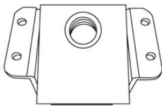
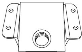
7 MODE button
8 Large screw thread (for the clamping system and the clamp screw)
9 Clamping system
10 Metal clamp screw

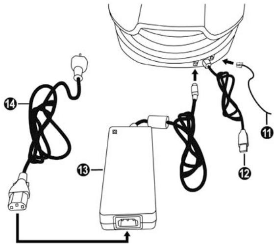
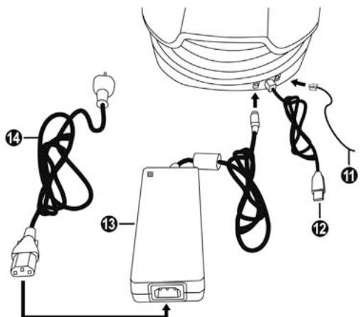
11 Pedal set cable and connector
12 Steering wheel cable and USB connector
13 Mains adaptor
14 Mains adaptor power cable

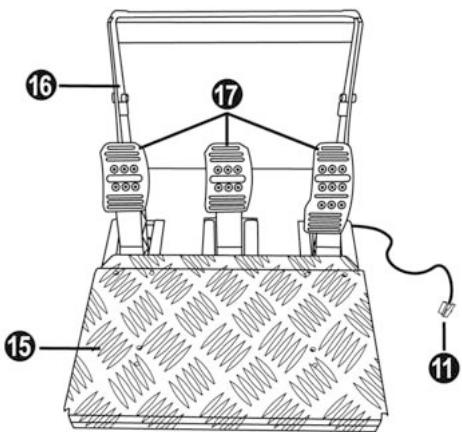
11 Pedal set cable and connector
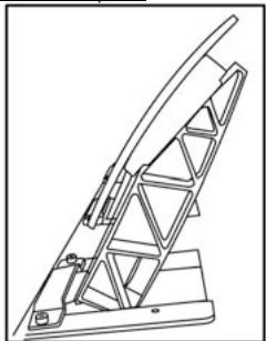
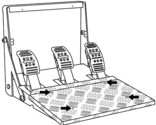
15 Removable foot rest
16 Arch
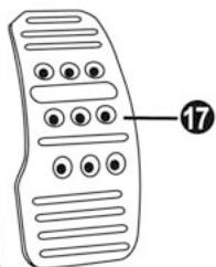
17 Removable pedal set
18 Removable "Realistic Brake" MOD (not installed by default)
19 2mm Allen key, supplied
20 2.5mm Allen key, supplied
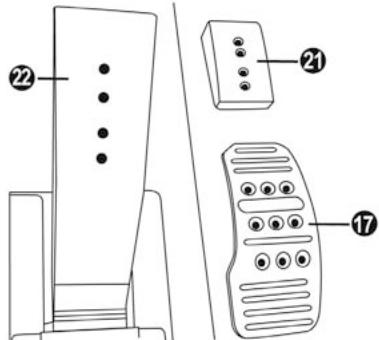
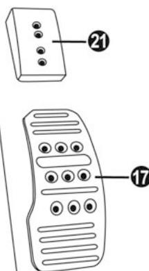
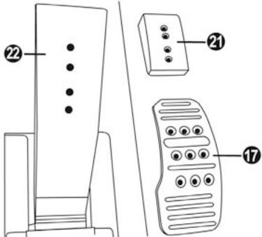
17 Metal head
21 Plastic Head Support
22 Pedal arm
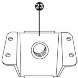
23 Removable metal stop (not installed by default)

WARNING
Before you use this product, please read this documentation carefully and keep it safe should you need to consult it later.

Warning - Electric shock
- Store the product in a dry location and do not expose it to dust or sunlight.
- Respect the connection direction.
- Do not twist or pull the connectors and cables.
- Do not spill any liquid on the product or its connectors.
- Do not short-circuit the product.
- Never dismantle the product (except to adjust the pedal set if necessary); do not throw it onto a fire and do not expose it to high temperatures.
- Do not use any adaptors other than the mains adaptor provided with the "T500 RS".
- Do not use the mains adaptor if its connectors or cables are damaged, split or broken.
- Make sure that the mains adaptor's power cable is perfectly inserted into the wall socket.
- If the steering wheel is operating unusually (if it is emitting any abnormal sounds, heat or odours), stop using it immediately, disconnect the power cable from the socket and disconnect the other cables.
- If you are not going to be using the steering wheel for an extended period, disconnect the mains adaptor from the wall socket.

Air vents
Make sure that you do not block any of the air vents on the steering wheel base. For optimum ventilation, respect the points below:
- Position the base at least 10 cm away from any wall surfaces.
- Do not place the base in any tight spaces.
- Do not cover the base.
- Do not let any dust build up on the air vents.

Warning - Injuries due to force feedback and repeated movements
Playing with a force-feedback steering wheel may cause muscle or joint pain. To avoid any problems:
Avoid lengthy gaming periods.
Take 10 to 15 minute breaks after each hour of play.
If you feel any fatigue or pain in your hands, wrists, arms, feet or legs, stop playing and rest for a few hours before you start playing again.
If the symptoms or pain indicated above persist when you start playing again, stop playing and consult your doctor.
Keep out of children's reach.
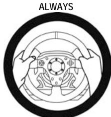
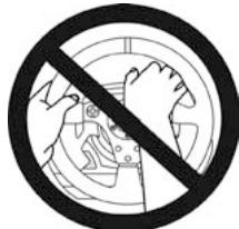
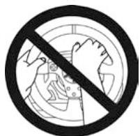
During games, always leave both hands correctly positioned on the steering wheel without letting it go completely.
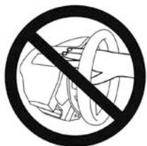
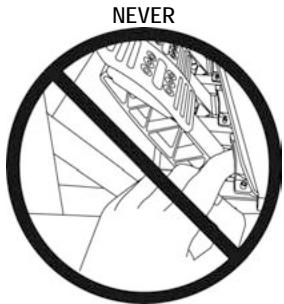
During game calibration, never place your hand or arm inside the steering wheel.
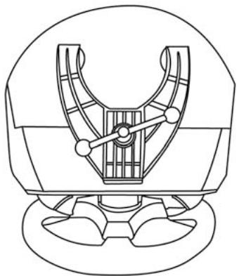
Check the steering wheel base is carefully clamped as per manual's instructions.
* After each use, put the warning notice back in its original place on the wheel's shaft, to warn any potential new users.

To be handled only by users 16 years of age or older
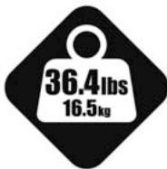
HEAVY PRODUCT
Be careful not to drop the product on yourself or on anyone else!
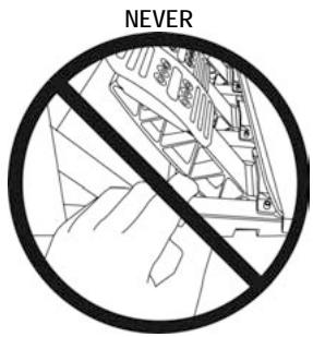
NEVER
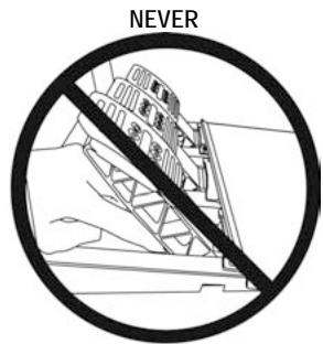
NEVER
- Keep the pedal set out of children's reach.
- Do not remove the protections placed on the pedal arms.
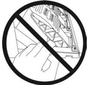
- During games, never place your fingers near the sides of the pedals.
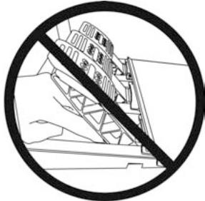
- During games, never place your fingers near the rear base of the pedals.
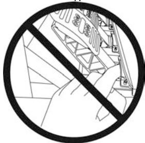
- During games, never place your fingers near the front base of the pedals.


Warning - Pedal set pinch hazard when not playing
- Store the pedal set in a safe place, and keep it out of children's reach.
- Do not remove the protections placed on the pedal arms.
INSTALLING THE WHEEL
Fixing the wheel to a Table or Desk
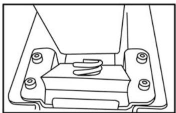
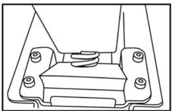
- Place the wheel on a table or another flat surface.
- Place the clamp screw (10) in the table clamp (9) then screw the clamping unit (anti-clockwise) into the large screw thread (8) located under the wheel until it is perfectly stable.
ALWAYS

NEVER
CAUTION: Never screw the clamp screw into the clamping system on its own! (this may damage the steering wheel).
| ASSEMBLY / DISASSEMBLY | |
| To tighten: Screw anti-clockwise | |
| To loosen: Unscrew clockwise |
Attaching the steering wheel and pedal set to a cockpit
- Place the steering wheel on the Cockpit's tablet.
- Tighten 2 "M6" screws (not supplied) into the Cockpit table and into the 2 small screw threads under the wheel.
Important note for the Wheel: These screws must not be longer than 12mm to avoid damaging the components inside the base.
- If necessary, screw in the standard clamping system (into the large screw thread).
- In the same way, attach the Pedal set using the small screw threads underneath it. Note for the Pedal set: In certain cockpits the "Floor position" (F1 type) will be more user-friendly. On others the "Suspended position (GT/Rally type)" will be more comfortable. Do not hesitate to test the different possible settings for more comfort.
INSTALLATION ON PLAYSTATION®3
- Connect the pedal set to the steering wheel by plugging in its connector (11) at the back of the wheel.
- Connect the mains adaptor to the wheel (13) by plugging in its connector to the back of the wheel.
- Connect the mains adaptor to its power cable (14).
Note: To be sure that the 2 elements are perfectly connected, push the power cable's connector into the mains adaptor socket firmly.
- Connect the mains cable (14) to a socket.
- Connect the wheel's USB connector (12) to the console's No. 1 port.
You are now ready to play!
AUTOMATIC CALIBRATION FOR THE WHEEL AND PEDALS
The wheel calibrates itself automatically once the mains adaptor and the USB connector are connected. This operation will cause the steering wheel to move quickly 1080^ to the left and right before coming to its final position in the center.

CAUTION:
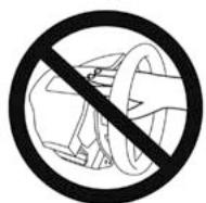
When calibrating the steering wheel
never touch the wheel
(this may mislead the calibration or cause injury).
The pedals are also calibrated automatically once they have been pressed a few times.
TROUBLESHOOTING & TIPS
- My wheel and my pedals don't work correctly or appear to be improperly calibrated:
Switch off your console, completely disconnect your wheel including all cables (with the mains adaptor and the pedal set) and restart your game.
- There are various tips and help features (not included in this manual) available on the website http://ts.thrustmaster.com in the Technical Support category.
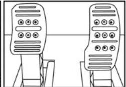
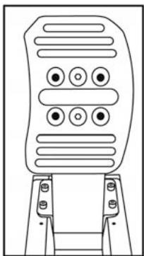
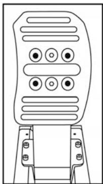
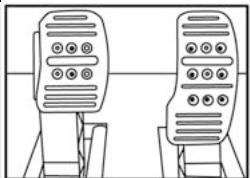
CONFIGURING THE PEDALS
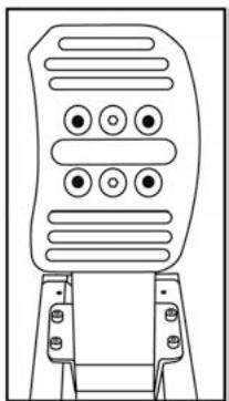
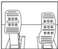
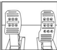
Each of the 3 pedals features:
-A Metal Head (17)" with several perforations
(9 for the Accelerator - 6 for the Brake - 6 for the Clutch)
- A "Plastic Head Support (21)" (between the head and the arm) with 4 perforations
-A Metal Arm (22)with 4 perforations
CAUTION: To avoid any calibration problems, always disconnect the USB cable from your steering wheel before adjusting the settings on your pedal set.
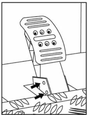
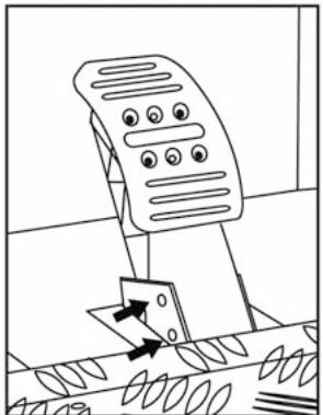
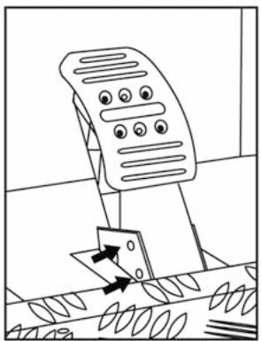
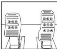
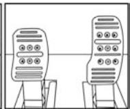
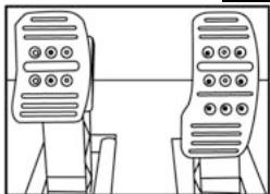
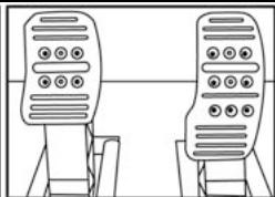
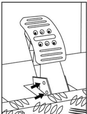
Adjusting the Pedal HEIGHT
- Using the 2.5mm Allen key supplied (20) loosen the 2 screws holding the "Metal Head (17) and its support (21)"
- Once this is done, select the height you want and tighten the screws again.
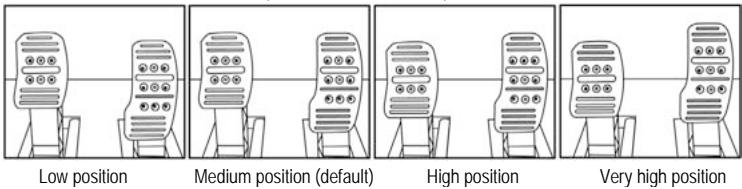
Examples with the accelerator pedal:
Number of height positions possible per pedal:
- 4 for the Accelerator pedal
- 2 for the Brake pedal
-2 for the Clutch pedal
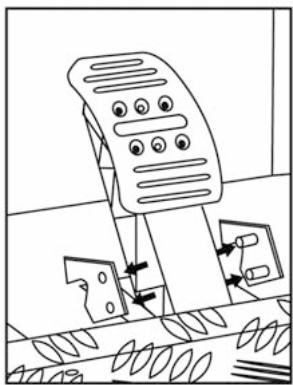
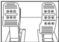
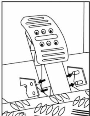
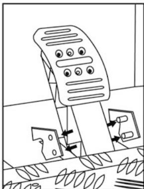
Adjusting the Pedal SPACING
- Using the 2.5mm Allen key supplied (20) loosen the 2 screws holding the "Metal Head (17) and its support (21)"
- Once you have done so, select your position (to the left, in the center or to the right) then tighten the screws.

Examples with the brake pedal:
Left position

Center position (default)
Right position
Number of spacing positions possible per pedal:
- 3 for the Accelerator pedal
- 3 for the Brake pedal
- 3 for the Clutch pedal
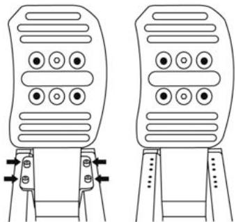
Adjusting the Pedal TILT
- Using the 2.5mm Allen key supplied (20) loosen the 2 screws holding the "Metal Head (17) and its support (21)"
- Once you have done so, turn the "Plastic Head Support (21)" over by 180^ then tighten the screws.
Examples with the accelerator pedal:
Less tilted position
More tilted position (default)
Number of tilt positions possible per pedal:
- 2 for the Accelerator pedal
- 2 for the Brake pedal
-2 for the Clutch pedal

CAUTION:
To adjust the TRAVEL and resistance FORCE for the Brake pedal, you must remove the transparent plastic pinch-hazard protector (protecting the brake pedal), and install the included metal stop. By doing so, you will no longer benefit from the intended protection against pinch hazards.
To restore your protection against pinch hazards, you must remove the metal stop and reinstall the transparent plastic pinch-hazard protector in its former location.
THRUSTMASTER® DISCLAIMS ALL RESPONSIBILITY FOR ANY INJURIES CAUSED BY REMOVAL OF THE PINCH-HAZARD PROTECTOR OR INSTALLATION OF THE METAL STOP
- Unscrew the 2 screws holding the pinch-hazard protector on the brake pedal arm.


- Install the metal stop (23) at the rear of the brake pedal arm.

- Select your position (up, in the center or down) then tighten the screws using the 2.5mm Allen key supplied (20).

Long run position & High resistance (default)
Short run position & Low resistance
Number of possible travel or resistance positions:
-
Long travel with resistance of around 10Kg (22lbs)
-
Medium travel with resistance of around 8.5Kg (18.7lbs)
-
Short travel with resistance of around 7Kg (15.4lbs)
Note: the longer the travel the higher the pedal resistance
(and vice versa)

CAUTION:
To install the "Realistic Brake" MOD, you must remove the transparent plastic pinch-hazard protector (protecting the brake pedal), and install the included metal stop. By doing so, you will no longer benefit from the intended protection against pinch hazards.
To restore your protection against pinch hazards, you must remove the metal stop and reinstall the transparent plastic pinch-hazard protector in its former location.
TRUSTMASTER DISCLAIMS ALL RESPONSIBILITY FOR ANY INJURIES CAUSED BY REMOVAL OF THE PINCH-HAZARD PROTECTOR OR INSTALLATION OF THE METAL STOP
This MOD enables different sensations and resistance when braking.
Each user must decide whether or not to install it according to their preferences.
- Unscrew the 2 screws holding the pinch-hazard protector on the brake pedal arm.
- Install the MOD fully and tightly into the bottom of the "Metal Stop" cavity.
- For strong resistance: position the MOD against the Upper wall.
- For even stronger resistance: position the MOD against the Lower wall.
Position against the Upper wall (Resistance of around 14Kg/30.8lbs)
Position against the Lower wall (Resistance of around 16Kg/35.2lbs)
- Once you have done so, tighten the "Metal Stop" (23) at the rear of the pedal arm
Position against the Upper wall (Resistance of around 14Kg/30.8lbs)
Position against the Lower wall (Resistance of around 16Kg/35.2lbs)
Important note:
To avoid any calibration problems, the "Realistic Brake" MOD must only be installed in "Long Run" position
(do not install it in "Medium Run" or "Short Run" position)
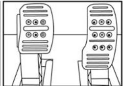
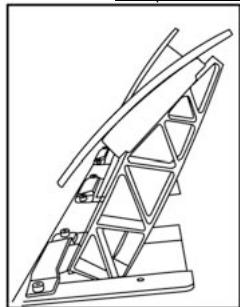
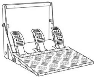
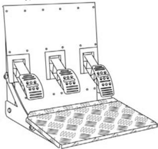
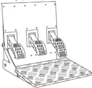
TURING THE PEDAL SET POSITION OVER
The "T500 RS" pedal set has a unique design (patent pending) that allows for a choice of 2 positions:
- Floor position (F1 type)
- Suspended position (GT/Rally type)
By default, the pedal set is delivered in "Floor" position (F1 type)
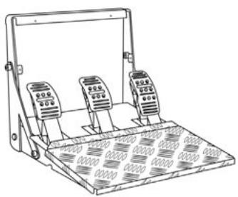
Floor position (F1 type)
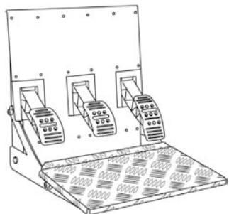
Suspended position (GT/Rally type)
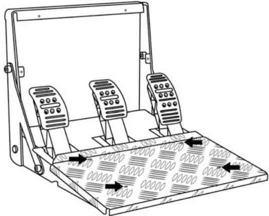
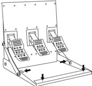
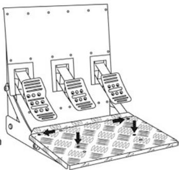
REVERSING THE PEDAL SET PHYSICALLY
- Using the 2mm Allen key (19) loosen the 4 screws holding the "Removable Foot Rest (15)"
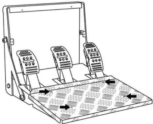
- Turn the pedal set over 90^ then tighten the "Foot Rest" again on the 4 screw threads located on the "Arch (16)"
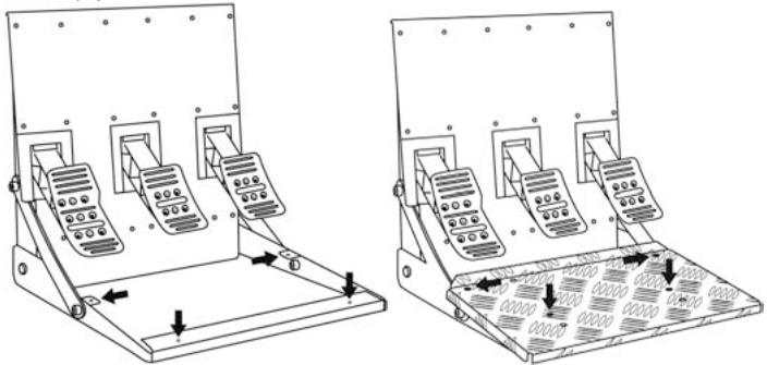
- Using the 2.5mm Allen key (20) loosen the 3 "Metal Heads (17)" to turn them over 180^ and reverse the Accelerator head and the Clutch head.

You are now ready to play!
ELECTRONIC REVERSAL for the accelerator & clutch pedals
When you turn over the pedal set position: simply press the MODE button (7) to reverse the accelerator and clutch pedals electronically
(the LED colour tells you the position you have chosen)
| PEDAL SET POSITION | LED (6) colour |
| ON THE FLOOR (F1 type)(installed by default) | RED |
| SUSPENDED (GT/Rally type) | GREEN |
Once you have done this the selected position is stored immediately
in the wheel's internal memory
TECHNICAL SUPPORT
If you encounter a problem with your product, please go to http://ls.thrustmaster.com and click Technical Support. From there you will be able to access various utilities (Frequently Asked Questions (FAQ), the latest versions of drivers and software) that may help to resolve your problem. If the problem persists, you can contact the Thrustmaster products technical support service ("Technical Support"):
By email:
In order to take advantage of technical support by email, you must first register online. The information you provide will help the agents to resolve your problem more quickly. Click Registration on the left-hand side of the Technical Support page and follow the on-screen instructions. If you have already registered, fill in theUsername and Password fields and then click Login.
By telephone:
| United Kingdom | 08450800942 Charged at local rate | Monday to Saturday from 8 a.m. to 7 p.m. |
| Denmark | 80887690 Free | Monday to Saturday from 9 a.m. to 8 p.m. (English) |
| Sweden | 0200884567 Free | Monday to Saturday from 9 a.m. to 8 p.m. (English) |
| Finland | 0800 913060 Free | Monday to Saturday from 10 a.m. to 9 p.m. (English) |
Hours of operation and telephone numbers are subject to change. Please visit http://hts.thrustmaster.com for the most up-to-date Technical Support contact information.
WARRANTY INFORMATION
Worldwide, Guillemot Corporation S.A. ("Guillemot") warrants to the consumer that this Thrustmaster product will be free from material defects and manufacturing flaws for a period of two (2) years from the original date of purchase. Should the product appear to be defective during the warranty period, immediately contact Technical Support, who will indicate the procedure to follow. If the defect is confirmed, the product must be returned to its place of purchase (or any other location indicated by Technical Support).
Within the context of this warranty, the consumer's defective product will, at Technical Support's option, be either repaired or replaced. Where authorized by applicable law, the full liability of Guillemot and its subsidiaries (including for indirect damages) is limited to the repair or replacement of the Thrustmaster product. The consumer's legal rights with respect to legislation applicable to the sale of consumer goods are not affected by this warranty.
This warranty shall not apply: (1) if the product has been modified, opened, altered, or has suffered damage as a result of inappropriate or abusive use, negligence, an accident, normal wear, or any other cause not related to a material defect or manufacturing flaw; (2) in the event of failure to comply with the instructions provided by Technical Support; (3) to software not published by Guillemot, said software being subject to a specific warranty provided by its publisher.
COPYRIGHT
© 2010 Guillemot Corporation S.A. All rights reserved. Thrustmaster® is a registered trademark of Guillemot Corporation S.A.
and PlayStation are registered trademarks of Sony Computer Entertainment Inc. is a trademark of Sony Computer Entertainment Inc. and GRAN TURISMO are registered trademarks of Sony Computer Entertainment Inc. All rights reserved.
All other trademarks and brand names are hereby acknowledged and are property of their respective owners. Illustrations not binding. Contents, designs and specifications are subject to change without notice and may vary from one country to another. Made in China.
TouchSense® Technology licensed from Immersion Corporation. Protected by one or more of the following patents:
U.S. Patents: 5185561, 5389865, 5459382, 5589854, 5629594, 5691898, 5721566, 5734373, 5767839, 5805140, 5831408, 5844392, 5857986, 5907487, 5929607, 5929846, 5959613, 6020875, 6020876, 6057828, 6078308, 6088017, 6100874, 6104158, 6104382, 6128006, 6147674, 6154198, 6184868, 61911774, 6201533, 6211861, 6219032, 6219033, 6243078, 6246390, 6252579, 6252583, 6271833, 6275213, 6278439, 6288705, 6292170, 6292174, 6310605, 6317116, 6343349, 6348911, 6380925, 6400352, 6411276, 6424333, 6437771, 6448977, 6469692, 6468872, 6563487, 6580417, 6636197, 6639581, 6661403, 6680729, 6693626, 6697044, 6670401, 6705871, 6707443, 6715045, 6717573, 6801008, 6816148, 6850222, 6864877, 6894678, 6903721, 6956558, 6982700, 7023423, 7024625, 7039866, 7091950, 7106305, 7106313, 7131073, 7154470, 7182691, 7193607, 7199790, 7209117, 7209118, 7218310, 7233476, 7249951, 7253803, 7283123, 7299321, 7327348, 7345672, 7423631, 7425675, 7446702, 74546821, 7477237, 7502011, 7557794, 7564444, 7567232, 7623114, 7659473, 7688310, RE40341, and RE40808.
ENVIRONMENTAL PROTECTION RECOMMENDATION

In the European Union: At the end of its working life, this product should not be disposed of with standard household waste, but rather dropped off at a collection point for the disposal of Waste Electrical and Electronic Equipment (WEEE) for recycling.
This is confirmed by the symbol found on the product, user manual or packaging.
Depending on their characteristics, the materials may be recycled. Through recycling and other forms of processing Waste Electrical and Electronic Equipment, you can make a significant contribution towards helping to protect the environment.
Please contact your local authorities for information on the collection point nearest you.
For all other countries: Please adhere to local recycling laws for electrical and electronic equipment.
Retain this information. Colours and decorations may vary.
Plastic fasteners and adhesives should be removed from the product before it is used.
Référence : 5075840
www.thrustmaster.com

N2035
C
T50CRS
For:PlayStation®3
User Manual


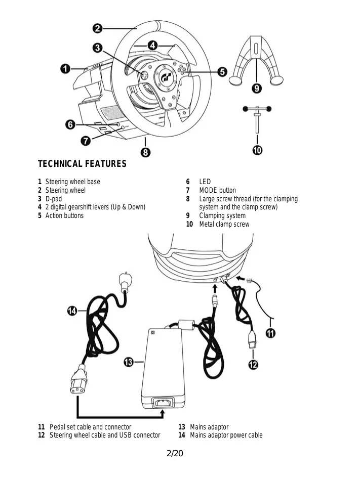
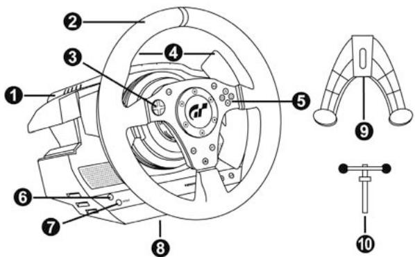
TECHNICAL FEATURES
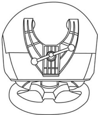
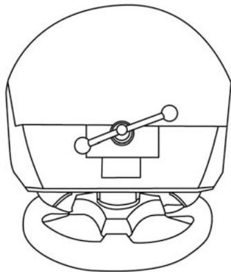
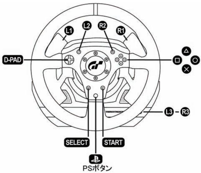
1 Steering wheel base
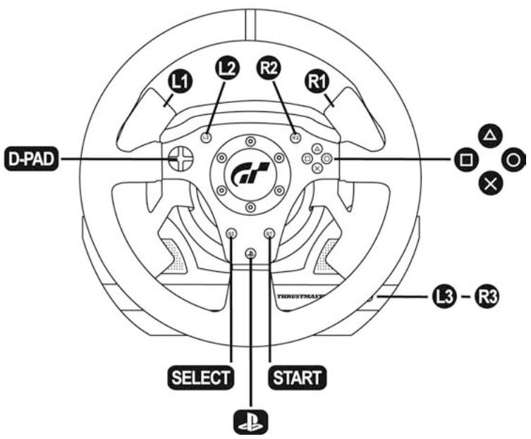
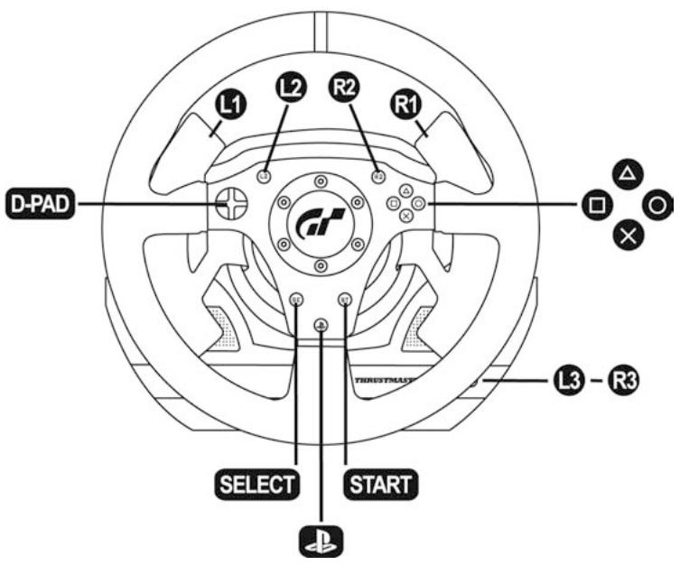
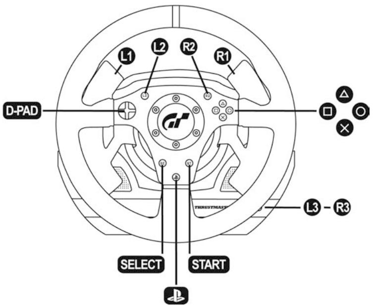
2 Steering wheel
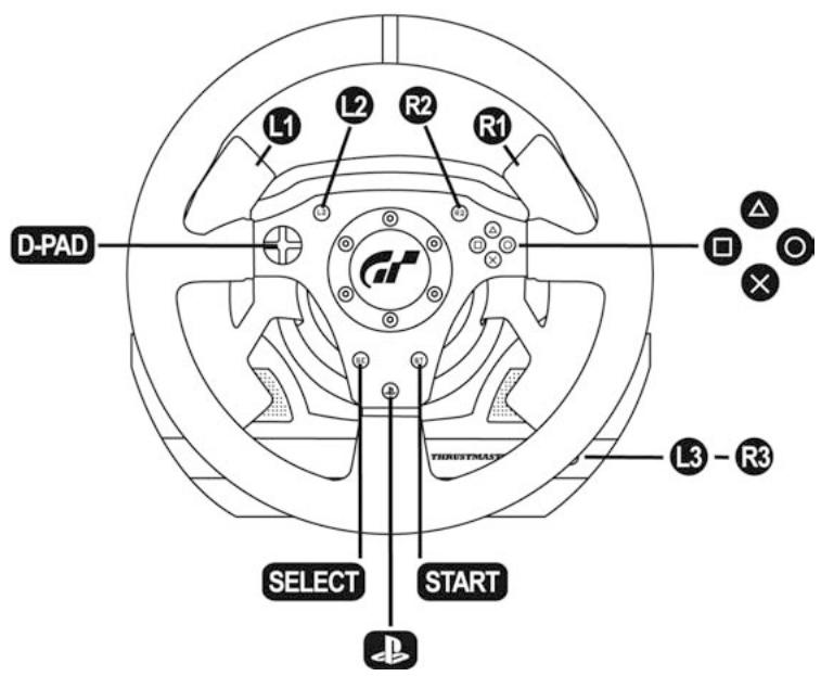
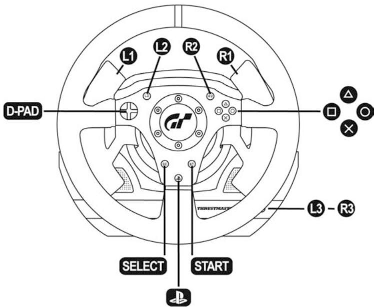
3 D-pad
4 2 digital gearshift levers (Up & Down)
5 Action buttons
6 LED
7 MODE button
8 Large screw thread (for the clamping system and the clamp screw)
9 Clamping system
10 Metal clamp screw
11 Pedal set cable and connector
12 Steering wheel cable and USB connector
13 Mains adaptor
14 Mains adaptor power cable
11 Pedal set cable and connector
15 Removable foot rest
16 Arch
17 Removable pedal set

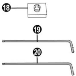
18 Removable "Realistic Brake" MOD (not installed by default)
19 2mm Allen key, supplied
20 2.5mm Allen key, supplied

17 Metal head
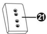
21 Plastic Head Support
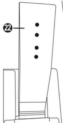
22 Pedal arm
23 Removable metal stop (not installed by default)
WARNING
Before you use this product, please read this documentation carefully and keep it safe should you need to consult it later.

Warning - Electric shock
- Store the product in a dry location and do not expose it to dust or sunlight.
- Respect the connection direction.
- Do not twist or pull the connectors and cables.
- Do not spill any liquid on the product or its connectors.
- Do not short-circuit the product.
- Never dismantle the product (except to adjust the pedal set if necessary); do not throw it onto a fire and do not expose it to high temperatures.
- Do not use any adaptors other than the mains adaptor provided with the "T500 RS".
- Do not use the mains adaptor if its connectors or cables are damaged, split or broken.
- Make sure that the mains adaptor's power cable is perfectly inserted into the wall socket.
- If the steering wheel is operating unusually (if it is emitting any abnormal sounds, heat or odours), stop using it immediately, disconnect the power cable from the socket and disconnect the other cables.
- If you are not going to be using the steering wheel for an extended period, disconnect the mains adaptor from the wall socket.

Air vents
Make sure that you do not block any of the air vents on the steering wheel base. For optimum ventilation, respect the points below:
- Position the base at least 10 cm away from any wall surfaces.
- Do not place the base in any tight spaces.
- Do not cover the base.
- Do not let any dust build up on the air vents.

Warning – Injuries due to force feedback and repeated movements
Playing with a force-feedback steering wheel may cause muscle or joint pain. To avoid any problems:
- Avoid lengthy gaming periods.
- Take 10 to 15 minute breaks after each hour of play.
- If you feel any fatigue or pain in your hands, wrists, arms, feet or legs, stop playing and rest for a few hours before you start playing again.
- If the symptoms or pain indicated above persist when you start playing again, stop playing and consult your doctor.
- Keep out of children's reach.
- During games, always leave both hands correctly positioned on the steering wheel without letting it go completely.
- During game calibration, never place your hand or arm inside the steering wheel.
- Check the steering wheel base is carefully clamped as per manual's instructions.
- After each use, put the warning notice back in its original place on the wheel's shaft, to warn any potential new users.

To be handled only by users 16 years of age or older

HEAVY PRODUCT

Be careful not to drop the product on yourself or on anyone else!

NEVER

NEVER
- Keep the pedal set out of children's reach.
- Do not remove the protections placed on the pedal arms.
- During games, never place your fingers near the sides of the pedals.
- During games, never place your fingers near the rear base of the pedals.
- During games, never place your fingers near the front base of the pedals.


Warning - Pedal set pinch hazard when not playing
- Store the pedal set in a safe place, and keep it out of children's reach.
- Do not remove the protections placed on the pedal arms.
INSTALLING THE WHEEL
Fixing the wheel to a Table or Desk
- Place the wheel on a table or another flat surface.
- Place the clamp screw (10) in the table clamp (9) then screw the clamping unit (anti-clockwise) into the large screw thread (8) located under the wheel until it is perfectly stable.

ALWAYS
NEVER

CAUTION: Never screw the clamp screw into the clamping system on its own! (this may damage the steering wheel).
| ASSEMBLY / DISASSEMBLY | |
| To tighten: Screw anti-clockwise | |
| To loosen: Unscrew clockwise |
Attaching the steering wheel and pedal set to a cockpit
- Place the steering wheel on the Cockpit's tablet.
- Tighten 2 "M6" screws (not supplied) into the Cockpit table and into the 2 small screw threads under the wheel.
Important note for the Wheel: These screws must not be longer than 12mm to avoid damaging the components inside the base.
- If necessary, screw in the standard clamping system (into the large screw thread).
- In the same way, attach the Pedal set using the small screw threads underneath it. Note for the Pedal set: In certain cockpits the "Floor position" (F1 type) will be more user-friendly. On others the "Suspended position (GT/Rally type)" will be more comfortable. Do not hesitate to test the different possible settings for more comfort.
INSTALLATION ON PLAYSTATION®3
- Connect the pedal set to the steering wheel by plugging in its connector (11) at the back of the wheel.
- Connect the mains adaptor to the wheel (13) by plugging in its connector to the back of the wheel.
- Connect the mains adaptor to its power cable (14).
Note: To be sure that the 2 elements are perfectly connected, push the power cable's connector into the mains adaptor socket firmly.
- Connect the mains cable (14) to a socket.
- Connect the wheel's USB connector (12) to the console's No. 1 port.
You are now ready to play!
AUTOMATIC CALIBRATION FOR THE WHEEL AND PEDALS
The wheel calibrates itself automatically once the mains adaptor and the USB connector are connected. This operation will cause the steering wheel to move quickly 1080^ to the left and right before coming to its final position in the center.

CAUTION:
When calibrating the steering wheel
never touch the wheel
(this may mislead the calibration or cause injury).
The pedals are also calibrated automatically once they have been pressed a few times.
TROUBLESHOOTING & TIPS
- My wheel and my pedals don't work correctly or appear to be improperly calibrated:
Switch off your console, completely disconnect your wheel including all cables (with the mains adaptor and the pedal set) and restart your game.
- There are various tips and help features (not included in this manual) available on the website http://ts.thrustmaster.com in the Technical Support category.
CONFIGURING THE PEDALS
Each of the 3 pedals features:
-A Metal Head (17) with several perforations
(9 for the Accelerator - 6 for the Brake - 6 for the Clutch)
- A "Plastic Head Support (21)" (between the head and the arm) with 4 perforations
-A Metal Arm (22)with 4 perforations
CAUTION: To avoid any calibration problems, always disconnect the USB cable from your steering wheel before adjusting the settings on your pedal set.
Adjusting the Pedal HEIGHT
- Using the 2.5mm Allen key supplied (20) loosen the 2 screws holding the Metal Head (17) and its support (21)
- Once this is done, select the height you want and tighten the screws again.
Examples with the accelerator pedal:
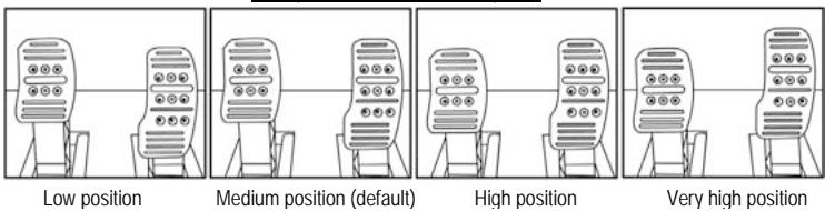
Very high position
Number of height positions possible per pedal:
- 4 for the Accelerator pedal
-2 for the Brake pedal
-2 for the Clutch pedal
Adjusting the Pedal SPACING
- Using the 2.5mm Allen key supplied (20) loosen the 2 screws holding the "Metal Head (17) and its support (21)"
- Once you have done so, select your position (to the left, in the center or to the right) then tighten the screws.
Examples with the brake pedal:
Left position
Center position (default)

Right position
Number of spacing positions possible per pedal:
- 3 for the Accelerator pedal
- 3 for the Brake pedal
- 3 for the Clutch pedal
Adjusting the Pedal TILT
- Using the 2.5mm Allen key supplied (20) loosen the 2 screws holding the "Metal Head (17) and its support (21)"
- Once you have done so, turn the "Plastic Head Support (21)" over by 180^ then tighten the screws.

Examples with the accelerator pedal:
Less tilted position

More tilted position (default)
Number of tilt positions possible per pedal:
- 2 for the Accelerator pedal
- 2 for the Brake pedal
-2 for the Clutch pedal

CAUTION:
To adjust the TRAVEL and resistance FORCE for the Brake pedal, you must remove the transparent plastic pinch-hazard protector (protecting the brake pedal), and install the included metal stop. By doing so, you will no longer benefit from the intended protection against pinch hazards.
To restore your protection against pinch hazards, you must remove the metal stop and reinstall the transparent plastic pinch-hazard protector in its former location.
THRUSTMASTER® DISCLAIMS ALL RESPONSIBILITY FOR ANY INJURIES CAUSED BY REMOVAL OF THE PINCH-HAZARD PROTECTOR OR INSTALLATION OF THE METAL STOP
- Unscrew the 2 screws holding the pinch-hazard protector on the brake pedal arm.
- Install the metal stop (23) at the rear of the brake pedal arm.
- Select your position (up, in the center or down) then tighten the screws using the 2.5mm Allen key supplied (20).
Long run position & High resistance (default)
Short run position & Low resistance
Number of possible travel or resistance positions:
-
Long travel with resistance of around 10Kg (22lbs)
-
Medium travel with resistance of around 8.5Kg (18.7lbs)
-
Short travel with resistance of around 7Kg (15.4lbs)
Note: the longer the travel the higher the pedal resistance
(and vice versa)

CAUTION:
To install the "Realistic Brake" MOD, you must remove the transparent plastic pinch-hazard protector (protecting the brake pedal), and install the included metal stop. By doing so, you will no longer benefit from the intended protection against pinch hazards.
To restore your protection against pinch hazards, you must remove the metal stop and reinstall the transparent plastic pinch-hazard protector in its former location.
TRUSTMASTER DISCLAIMS ALL RESPONSIBILITY FOR ANY INJURIES CAUSED BY REMOVAL OF THE PINCH-HAZARD PROTECTOR OR INSTALLATION OF THE METAL STOP
This MOD enables different sensations and resistance when braking.
Each user must decide whether or not to install it according to their preferences.
- Unscrew the 2 screws holding the pinch-hazard protector on the brake pedal arm.

- Install the MOD fully and tightly into the bottom of the "Metal Stop" cavity.
- For strong resistance: position the MOD against the Upper wall.
- For even stronger resistance: position the MOD against the Lower wall.
Position against the Upper wall (Resistance of around 14Kg/30.8lbs)


Position against the Lower wall (Resistance of around 16Kg/35.2lbs)
- Once you have done so, tighten the "Metal Stop" (23) at the rear of the pedal arm

Position against the Upper wall (Resistance of around 14Kg/30.8lbs)

Position against the Lower wall (Resistance of around 16Kg/35.2lbs)
Important note:
To avoid any calibration problems, the "Realistic Brake" MOD must only be installed in "Long Run" position
(do not install it in "Medium Run" or "Short Run" position)
TURING THE PEDAL SET POSITION OVER
The "T500 RS" pedal set has a unique design (patent pending) that allows for a choice of 2 positions:
- Floor position (F1 type)
- Suspended position (GT/Rally type)
By default, the pedal set is delivered in "Floor" position (F1 type)
Floor position (F1 type)

Suspended position (GT/Rally type)
REVERSING THE PEDAL SET PHYSICALLY
- Using the 2mm Allen key (19) loosen the 4 screws holding the "Removable Foot Rest (15)"
- Turn the pedal set over 90^ then tighten the "Foot Rest" again on the 4 screw threads located on the "Arch (16)"
- Using the 2.5mm Allen key (20) loosen the 3 "Metal Heads (17)" to turn them over 180^ and reverse the Accelerator head and the Clutch head.

You are now ready to play!
ELECTRONIC REVERSAL for the accelerator & clutch pedals
When you turn over the pedal set position: simply press the MODE button (7) to reverse the accelerator and clutch pedals electronically
(the LED colour tells you the position you have chosen)
| PEDAL SET POSITION | LED (6) colour |
| ON THE FLOOR (F1 type)(installed by default) | RED |
| SUSPENDED (GT/Rally type) | GREEN |
Once you have done this the selected position is stored immediately
in the wheel's internal memory
TECHNICAL SUPPORT
If you encounter a problem with your product, please go to http://ls.thrustmaster.com and click Technical Support. From there you will be able to access various utilities (Frequently Asked Questions (FAQ), the latest versions of drivers and software) that may help to resolve your problem. If the problem persists, you can contact the Thrustmaster products technical support service ("Technical Support"):
By email:
In order to take advantage of technical support by email, you must first register online. The information you provide will help the agents to resolve your problem more quickly. Click Registration on the left-hand side of the Technical Support page and follow the on-screen instructions. If you have already registered, fill in theUsername and Password fields and then click Login.
By telephone:
| United States | 1-866-889-5036Free | Monday to Friday from 9 a.m. to 8 p.m.Saturday from 8 a.m. to 2 p.m.(Eastern Standard Time)Monday to Friday from 6 a.m. to 5 p.m.Saturday from 5 a.m. to 11 a.m.(Pacific Standard Time) |
| Canada | 1-866-889-2181Free | Monday to Friday from 9 a.m. to 8 p.m.Saturday from 8 a.m. to 2 p.m.(Eastern Standard Time)Monday to Friday from 6 a.m. to 5 p.m.Saturday from 5 a.m. to 11 a.m.(Pacific Standard Time) |
Hours of operation and telephone numbers are subject to change. Please visit http://ts.thrustmaster.com for the most up-to-date Technical Support contact information.
WARRANTY INFORMATION
Worldwide, Guillemot Corporation S.A. ("Guillemot") warrants to the consumer that this Thrustmaster product will be free from material defects and manufacturing flaws for a period of two (2) years from the original date of purchase. Should the product appear to be defective during the warranty period, immediately contact Technical Support, who will indicate the procedure to follow. If the defect is confirmed, the product must be returned to its place of purchase (or any other location indicated by Technical Support).
Within the context of this warranty, the consumer's defective product will, at Technical Support's option, be either repaired or replaced. Where authorized by applicable law, the full liability of Guillemot and its subsidiaries (including for indirect damages) is limited to the repair or replacement of the Thrustmaster product. The consumer's legal rights with respect to legislation applicable to the sale of consumer goods are not affected by this warranty.
This warranty shall not apply: (1) if the product has been modified, opened, altered, or has suffered damage as a result of inappropriate or abusive use, negligence, an accident, normal wear, or any other cause not related to a material defect or manufacturing flaw; (2) in the event of failure to comply with the instructions provided by Technical Support; (3) to software not published by Guillemot, said software being subject to a specific warranty provided by its publisher.
Additional warranty provisions
In the United States of America and in Canada, this warranty is limited to the product's internal mechanism and external housing. Any applicable implied warranties, including warranties of merchantability and fitness for a particular purpose, are hereby limited to two (2) years from the date of purchase and are subject to the conditions set forth in this limited warranty. In no event shall Guillemot Corporation S.A. or its affiliates be liable for consequential or incidental damage resulting from the breach of any express or implied warranties. Some States/Provinces do not allow limitation on how long an implied warranty lasts or exclusion or limitation of incidental/consequential damages, so the above limitation may not apply to you. This warranty gives you specific legal rights, and you may also have other legal rights which vary from State to State or Province to Province.
DECLARATION OF CONFORMITY
CANADIAN COMPLIANCE NOTICE: this Class B digital apparatus meets all requirements of the Canadian Interference
Causing Equipment Regulations.
USA COMPLIANCE NOTICE: this equipment has been tested and found to comply with the limits for a Class B digital device, pursuant to Part 15 of the FCC rules. Operation is subject to the following two conditions:
(1) This device may not cause harmful interference, and
(2) This device must accept any interference received, including interference that may cause undesired operation.
These limits are designed to provide reasonable protection against harmful interference in a residential installation. This equipment generates, uses and can radiate radio frequency energy and, if not installed and used in accordance with the instructions, may cause harmful interference to radio communications. However, there is no guarantee that interference will not occur in a particular installation. If this equipment does cause harmful interference to radio or television reception, which can be determined by turning the equipment on and off, the user is encouraged to try to correct the interference by one or more of the following measures:
- Reorient or relocate the receiving antenna.
- Increase the separation between the equipment and receiver.
- Connect the equipment into an outlet on a circuit different from that to which the receiver is connected.
- Consult the dealer or an experienced radio/TV technician for help.
COPYRIGHT
© 2010 Guillemot Corporation S.A. All rights reserved. Thrustmaster® is a registered trademark of Guillemot Corporation S.A.
andPlayStationare registered trademarks of Sony Computer Entertainment Inc.23is a trademark of Sony
Computer Entertainment Inc. and GRAN TURISMO are registered trademarks of Sony Computer Entertainment Inc.
All rights reserved.
All other trademarks and brand names are hereby acknowledged and are property of their respective owners. Illustrations not binding. Contents, designs and specifications are subject to change without notice and may vary from one country to another. Made in China.
TouchSense® Technology licensed from Immersion Corporation. Protected by one or more of the following patents:
U.S. Patents: 5185561, 5389865, 5549382, 5589854, 5629594, 5691898, 5721566, 5734373, 5767839, 608017, 6100874, 6104158, 6104382, 6128006, 6147674, 6154198, 6184868, 6191774, 6201533, 6211861, 6219032, 6219033, 6243078, 6246390, 6252579, 6252583, 6271833, 6275213, 6278439, 6288705, 6292170, 6292174, 6310605, 6317116, 6343349, 6348911, 6380925, 6400352, 6411276, 6424333, 6437771, 6448977, 6469692, 6486872, 6563487, 6580417, 6636197, 6639581, 6661403, 6680729, 6693626, 6697044, 6704001, 6705871, 6707443, 6715045, 6717573, 6801008, 6816148, 6850222, 6864877, 6894678, 6903721, 6956558, 6982700, 7023423, 7024625, 7039866, 7091950, 7106305, 7106313, 7131073, 7154470, 7182691, 7193607, 7199790, 7209117, 7209118, 7218310, 7233476, 7249951, 7253803, 7283123, 7299321, 7327348, 7345672, 7423631, 7425675, 7446752, 7447604, 7456821, 7477237, 7502011, 7557794, 7564444, 7567232, 7623114, 7659473, 7688310, RE40341, and RE40808.
ENVIRONMENTAL PROTECTION RECOMMENDATION

In the European Union: At the end of its working life, this product should not be disposed of with standard household waste, but rather dropped off at a collection point for the disposal of Waste Electrical and Electronic Equipment (WEEE) for recycling.
This is confirmed by the symbol found on the product, user manual or packaging.
Depending on their characteristics, the materials may be recycled. Through recycling and other forms of processing Waste Electrical and Electronic Equipment, you can make a significant contribution towards helping to protect the environment.
Please contact your local authorities for information on the collection point nearest you.
For all other countries: Please adhere to local recycling laws for electrical and electronic equipment.
Retain this information. Colours and decorations may vary.
Plastic fasteners and adhesives should be removed from the product before it is used.
Reference: 5075854
www.thrustmaster.com
Position suspendue (type GT/Rallye)
INFORMATIONS RELATIVES A LA GARANTIE
www.thrustmaster.com

N2035
C

Position suspendue (type GT/Rallye)
INFORMATIONS RELATIVES A LA GARANTIE
www.thrustmaster.com
T50C/RS
Für:PlayStation ⑧ 3
Benutzerhandbuch

TECHNISCHE FEATURES
www.thrustmaster.com

N2035 C€
T50C
Voor:PlayStation®3
PROBLEEMOPISSING & TIPS
INFORMATIE MET BETREKKING TOT DE GARANTIE
www.thrustmaster.com

N2035 C€

Para:PlayStation®3
Manual del usuario

CHARACTERISTICAS TECNICAS
www.thrustmaster.com

N2035
C
Para:PlayStation ⑥ 3
Manual del usuario


CHARACTERISTICAS TECNICAS
www.thrustmaster.com
T50C/RS
Para:PlayStation®3
Manual do Utilizador


CHARACTERISTICAS TECNICAS
www.thrustmaster.com

N2035 C

Д�� PlayStation®3
Hnctpykunno3Kcnnyataun

TEXHNUECKOE YCTPOICTBO
1 Ba3a pyNeBcNCTeMbI
2 PyneBoe KOleco
3 IpeeknouateIb D-pad
4 2LHpOBoBx pIyara nepeKIOueHn(BBepx IN BHN3)
5 KhoTNI
6 INHdkaTOp
7 Khonka MODE (Pekim)
8 Pe3b6a PNO 60JIb6UO BINT (ДЯЗЖIMMa I 3aJIMMHO BINTa)
9 3axmM
10 MeTaNnueckn 3axmHbBnHT

11 Ka6eJIb cpa3bEmOM,ДЯппадл.
12 Ka6eIb cpa3bEmOM USB dIpyneBoro Koneca
Ipeed 3Kcnpyataauee daHnHO 3dEINNA BHNMaTeNbHO O3HaKOMbTeCb C hAcToaee HNCTpyKUnei COxpaHNTe ee B HndExHOM MecTe dIra Ha 6yduyee.

BhimaHne - onachoctb nopaxehn3neKtpueckm TOKOM!
*I3dJIeNcIeJyET xpaHnTB B cyXOM MceTe, n36eRaI nonaDaHnHa HrE O IIIN IN CONHeuHOr CBeta.
*O63aTeIbHcO c6JIIOJeHne IpaBnIbHOCTN IOKJIIOHeHn pa3bEmOB.
He donyckaetc nepekpyuBaHne pa3bEmOB n Ka6eNei; TaKke 3a HnX HeIb3r THyTb.
He donyckaetc nonapaanhe kukoctn Ha n3dene I erpa3bembl.
He donyckaetc KopoTkoe 3ambikaHne B ceni n3dennia.
3aπeuaetcpa36bnpatb M3deneB INhblx ζηλχ, KpOmepeRyIuPOBKn peIaIeN pπH Heo6xoIIMOCtN, 6bocatb M3deneB IOrHb N IOBBePratb ero BO3dECTBmIO BbICOKX TEmpepatyp.
He Doynyckaetca IcnoIb30BaHne Dpynx aadantepoB, KpOme ceTeBOrO adanTepa, BXoJaIeero B KOMnIeK TpoDyKra T500 RS.
Henlb3a IcNoIb3ObaTb cTeBcI aadTep C NOBpeXdEHbIMN, nOTpeCKabIMMscnCnOMaHHbIMN pa3bemAMm INK Ka6eJIaMn.
*Kabelb nitaHncaTeBoro aandaTepa cneJeYet HndexHo IIOKIIIOUaTb K pO3eTke.
^ B cnyae HnepomlBoro FOHNUMOHAPOBAHny Pnyeob CNTcEMbl (Pnp BO3HNHOBEHNI NOCTOPOHHX 3ByKOB, nepeperbe INI yanaexe) cIeayet HmEneJNO pKePATNt bCNOJIb3OBAHMe CNTcEMbl, BblKIOuHTb Ka6bI pINTAHNA I3 PO3EKIT NOTCOEIMHIT BCE OCTaIbHIE KABENI.
Ecnln npednolanaetc, YTO pynebaar cIcTeMa He 6ydt NcnoJb3ObaTbcra IpoDJIKHTeJIbHOE BpeM, OTKIOHHTe CTeBOI adAnTep Or p03eKn.

BeHTnJIaUHOHHbIe OTBepCTH
He donyckaetc 6bnKpObaHne BENTINIaONHbIX OTBepCTM Ha 63e pyneBOCCTEmbl. Ipn obecepeHnA ONTImaJIbHO BENTINIaUNBbIOHNTE CNeDyoUHue ykaazHnA:
*pa3MeuAnTe 6a3y Ha paaccToHn H MeHee 10 cm OT cTeH;
He pa3MeuaiTe 6a3y B CTeCHeHHOM IpocTpaHCTBe;
HnueM He NaKpbIbAaTe 6a3y;
* He Doonyckaite CKoJIeHnI NbJIi Ha BeHTNIaIOHbIX OTBepCTnx.

DeiCTBnA CNIOBOI O6paTHOIBCB3N
VcnoJIb3OBAHHe pyIeBO CnCTeMbICnIOBOB O6paTHOB CB83bO MOKET Bb3BaTb 6oJIb MblUax INCycTabaX.BoN36ekJAHne Ipo6nEM BblONIHNe TcpeDyUOme yCNOBn:
- He npoBOdnte 3a ngpoI npoDoJIxKInTeJIbHoe Bpemr;
- nocé kaxdoró yaca irpby dénaïte 10-15-MnHyTHbI nepepbIb;
*ecnB K nctax, 3aIaTbIax, npEIIeIbIax, cTOnax IIN Horax noBnIacb yCTanOCTb IIN 60Ib, pIekpatnte INpy I OTOxHInTe B TeueHHe NcckOblkXuCob, npEke Yem ChOBa PnCtUynIb K Inrpe;
*eCNI BblyeuKa3aHbIe PnI3Hakn IpoBbIyOTcA CHOBA npN BO3BpaUeHN K nIpe, IpeKpATte nIpy N o6paTntecb K bpa? - Dépçxnte CnCTemy BHe DoCTyNa DeTei;
* BO Bpemr Hrpbl npabnIbHO paacnoIarai Te obe pykn Ha pynBOM KOlece N He IIO3BOJIaTe Emy Bpaatbcra 6eckoHTpoHbO;
* BO Bpem KAIIN6pOBK INrpbI HN B KOeM Cnyae He 3acOBbBaIte pyK B pyJeBOE KOJIeCO. - Y6eIntecb, YTO 6a3a pyJeleBOrO KOleca HAdexKHO 3aKepeIeHa B COOTBeTCTBn C yKa3aHnA M N HCTpyKmN IO 3KnIpyAtuM.
*Pocle kaxdOrO nCnloIb30BaHnI B03BpaauTe npDynpDntIbHbI 3HaK Ha IcXoHoe MeCTO HpyJIeBOM BAJIe B CEJAX npDeIOCTepeJHnI B03MOKbIX HObIX NOL3OBaTEnE.

He donyckaetca nCnoIb3oBaHne IInzamM MoIoxe 16 net


He poHnIte n3dJIe Na ce6a nn Ha npynx nui!
HIKOKDA TAK
HIKOKDA TAK
- Dépçnítte neaɪnbýbì 6lòk Bνe doctуna déteɪ.
- He chimaite npedoxpanitei n c piharob neaie.
*BoBpMaIrpblHbKOEMcIyuaHe3acOBBaIaTe nIaNbUcIc60KOBbIX cTOpOH neIaJIbHorO 6Joka.
*BoBpMaIrpblHBNKoemClyuaeHe3acOBbIaBaiTeNaIbUbIONDpeaNc3aDHeCTOPOHbI.
*BoBpMaIgPbHnBKOEMcLyaeHe3acOBBaIaIbUbIeNanIbUbIeNepaIbHbI6JIOKcpePeHcSTOpOhbl.
HNKOFDA TAK
HNKOKDA TAK
HNKOKDA TAK

IpeynpexdHHe: Bo3MOxHcXaTne neaIbHoro 6noka BO BpeM npocToA
*XpaHnTe peJaIbHbI 6JOK B 6e3OpanchOM MeCTe BHe 30HbIOCTyNa DeTe.
* He ChnmaJte npedeoxpanteni CpbuarOB nepaJIe.
YCTAHOBKA PYJIEBOI CNTEMbl
3akpenenne pyneBoro koneca Ha cTone
- PacnoIoxnTe pyneBoe KOleco Ha cTone IIN INHOI pNOCKOIOBepxHocTN.
2.ПOMeCTTte 3aXMMHbBn BnHT (10)В OTBepCTne Ha 3aXMME (9)и 3akpyTtTe (POTINB YacCBOY BpeKNB) Bpe3b6 noD 6oIbSuO BnHT (8)Ha HIXKHei CTOpHO 6a3bl pyNeBOn CNTEmbl Do HAdexKHoiФICauCIn.
TOJIbKO TAK
HIKOKDA TAK
OCTOPOXHO! He 3aKpyuHbAe Te BnHT B 3axHMe, He npKpEnNB pyJb K cToNY! (B pOtnHBOM cnUyae BO3MOxHO NOBpeXdHe ne PyneBOI CNCTeMbI).
HnB Koem clyae He TporaIte pynb BO Bpemr
KannibpOKn!
(B npotnbHOM cnyae BO3MOxEn c6oJ KaIbPoBKn I
cepbe3HaTpaBMa).
IporpammmpoBaHne neaane TaKke BbInoHЯTcA bTOMaTUeCKn IocNe HeCKOJIbKx HaxaTm.
YCTPAHEHNE HENCIPABHOCTEIN COBETBI
-PyIb I neIaII pa60aIOT HeKOppeKTHO IIN 3aMeTbI pIpi3Hakn HeBepHO KAnIb6pOBKn.
BbIKJIOHTe KOHcOJIb, POJIHOCTbI OTKJIIOHTe BCE Ka6eJIOn OT pyJIeBOI CnCTEmbl (B TOM YHCNE cTeBOI aAnTep INeALII) INpe3aNyCTnte nRpy.
- Ha Be6-baie http://ts.thrustmaster.com, B pazdene Technical Support (TexNHueckay noedjka), npedctabJIeHO MHOKeCTBO COBETOB INpapBOcHbIX MATEpIaNIOB (HE BKIOUeHNbIX B hactoJyIO HNCTpyKUIO).
KOHΦIΓΥΡΙΝΟΒΑΗΝ ΠΕДΑΙΕ
KoNCTpykunna neaIae:
-MeTaNIIueckaJIIOUaJaKa(17)CHECKOJIbKIMMOTBepCTnAIMN
(9—πη πελαινα3a,6—πλπελαινtopmo3a,6—πη πελαινcμεπηκηη);
- nlaactkoBaa npoklaKa dna ploaakn (21) (MeKdy ploaakoN npbYarom) c 4 OTBepctnMM;
-MetanJIueckn pbIar neaII (22)c 4OTBepCTnAIM.

OCTOPOXHO! Bo n36eJHHe npo6Iem c KaIb6pOBKoB Cserda oTKIOUaHTe USB-Ka6eIb OTo pyNeBOrO KOleca neped perynuPobKo neJaen.
Pereynipobka BblCOTbl neaale
-C NOMOuBb BXoJauero B KOMNJIeK IeCTMrrpHOrO KIOUa 2,5 MM (20) OcTaNbTe 2 BNHTa, ydePKBaUoXh METaIIIueCeKYo NIOuaKy (17) IN POKnAky (21).
-Поссе 3тORA ВьберпгЕ hyхную ВьICOTу И ChObA 3akpyTnTE BnHTbl.
Ppimepbpeynpobkne naa ra3a:
Hn3Koe noJoxeHne
CpeHHeNoJoxKeHMe (yo mOny.)
BbICOKOE noJIOXeHne
Camao Bbckocn noXONKENH
KolnueCTBO BO3MOXhBIX NOLOXeHn DnI neDan:
-4dnnpeanra3a
-2ДпЯпдянТOPM03a
-2dna neaun cuenneHH
Perynpobka PACCTOHHm mexny nedaIIMn
- C NOMOusbxODAJeero B KOMIneKT IeCTMIRpaHnHO KIOUa 2,5 MM (20) Ocna6bTe 2 BVHTa, ydepKJBAAoHux MeTALINHeCKy IOIooaKy (17) n pOKnAky (21).
- Посл e3toro BvibepnTe HuxHoe nIoJxHeHne (IeBoe, zentpaIbHoe mI npaboe) n ChOba 3akpyTHTe BVHTbl.
PpimepbI perynilpoBkn neaIIN Topmo3a:
JIeBoe noJIOXeHne
LcHTpaIbHoe noIOxKeHne (no yMOnIu.)
PpabeO noJoxKeHne
KoIyHeCTBO BO3MOXHbIX NOIOKeHn DJIe neaII:
PnmeuHHe: Yem Tny6ke XoJ neaJI, Tem BbIe ee cnpotNBJeHne (HaobopOT)

Дя установки мodyня Realistic Brake MOD heo6xodnmo cHrtb np03paHbI pnaTknOBbI npedoxpahnteb (obecnevybaOoiu 3aunyt neDanBHO 6noka) u yctahOBHT metannueckn CTonOp, BXoJauB n B KomJIeKt. B pe3yIbTate 3TOr DeIcTBn yCTpaHreTCa 3auNTa OT CxATN npeJaTe.
Дль ВOCCTAHOBJIЕнna 3aunltbI CHIMNTE MetaJIINUeCKH CTONOPи NOCTaBte ПОЗpaHbI ПlaCTNKOBblпрdoxpaHNTelhaPexHee MeCTO.
KOMTANHTRUSTMASTER CHIMAET CCEBA BCKYIO OTBETCTBEHHOCTb 3A IIOBbIE TPABMbI, PONUeHHbIE BCJIEDCTBNE YDAJIENH NPEDOXPAHNTELC XATIN
3mom modynl no3eonrém doobimcra hOBix oUyueHui u conpomueHnru npu mopmoHnlu. Kaobni nonb3oBamel no c0eMy ycmompenu peuamaem, cnedyem n zu e2o ycmaanabnauamb.
- Otkpytnte 2 BnHTa, ydepxnbaioux npedoxpahnteIb cKaTna Ha pbHare ne daHn TopMo3a.
- Ocnabte 6oIbI n CHIMITE MeTaIINueckn ynp (no3aI np bIyara neJaTIp TOpMo3a).
-Плnotho ДО конца Вставы Мodyль вуглбение металл用电ору унopa.
-ДяВьсOKOTOCONPOTNBENHЯ:ВCTaBbTeMOdYbnapaJIpeMbHO3aDHeNCTeHKe.
-Дя ese 6oIbIeero cOnpoTnBHeHnry: BCTaBbTe MoDyIb npaIenneIbHo dHy.
PnnpnoHraToe noJoxKeHne (CTnlb GT/paII)
IPEBEOPAUHBAHNE IEDAJbHOrO BLOKA
-C NOMOJIbU WeCTnIRpaHHORO KJIIOUa 2 MM (19) OcnaIbTe 4 BnHTa, yDePxNBAOUIX CbeMHbYyIop IJRAHor (15)
www.thrustmaster.com

N2035 C€
T50CRS
Tα:PlayStation®3
Exyepidio xphonc
TEXNIKA XAPAKTHPIETIKA
Ipoosapouyn YPOYZ TErTal
Ipoosapouyn KAIISHE TReTal
www.thrustmaster.com

N2035
C
PlayStation®3 écin
Kullanim Kilavuzu

TEKNIK ÖZELLİKLER
1 Direksiyon govdesi
2 Direksiyon
3 D-pedi
4 2 djital vites kolu (Yukari ve Asaqi)
5 Eylemdugmeleri
6 LED
7 MODE dugmesi
8 Genis vida disi (kenetlememe sistemi ve sikmasvidasi icin)
9 Kenetleme sistemi
10 Metal sikma vidasi
www.thrustmaster.com

N2035 C€
T500RS
PlayStation®3 用
一一卡一卡二一
www.thrustmaster.com
Made in China.


:外箱

:外箱透明部

Thrustmaster is a division of the Guillemot Corporation group

- WARNING
- Warning - Electric shock
- Air vents
- Warning - Injuries due to force feedback and repeated movements
- Warning - Pedal set pinch hazard when not playing
- INSTALLING THE WHEEL
- Fixing the wheel to a Table or Desk
- Attaching the steering wheel and pedal set to a cockpit
- INSTALLATION ON PLAYSTATION®3
- AUTOMATIC CALIBRATION FOR THE WHEEL AND PEDALS
- CAUTION:
- TROUBLESHOOTING & TIPS
- CONFIGURING THE PEDALS
- Each of the 3 pedals features:
- Adjusting the Pedal HEIGHT
- Adjusting the Pedal SPACING
- Adjusting the Pedal TILT
- TURING THE PEDAL SET POSITION OVER
- REVERSING THE PEDAL SET PHYSICALLY
- ELECTRONIC REVERSAL for the accelerator & clutch pedals
- TECHNICAL SUPPORT
- By email:
- WARRANTY INFORMATION
- COPYRIGHT
- ENVIRONMENTAL PROTECTION RECOMMENDATION
- T50CRS
- For:PlayStation®3
- TECHNICAL FEATURES
- Warning – Injuries due to force feedback and repeated movements
- Additional warranty provisions
- DECLARATION OF CONFORMITY
- INFORMATIONS RELATIVES A LA GARANTIE
- T50C/RS
- TECHNISCHE FEATURES
- T50C
- PROBLEEMOPISSING & TIPS
- INFORMATIE MET BETREKKING TOT DE GARANTIE
- Para:PlayStation®3
- Manual del usuario
- CHARACTERISTICAS TECNICAS
- Para:PlayStation ⑥ 3
- Д�� PlayStation®3
- Hnctpykunno3Kcnnyataun
- TEXHNUECKOE YCTPOICTBO
- BhimaHne - onachoctb nopaxehn3neKtpueckm TOKOM!
- BeHTnJIaUHOHHbIe OTBepCTH
- DeiCTBnA CNIOBOI O6paTHOIBCB3N
- IpeynpexdHHe: Bo3MOxHcXaTne neaIbHoro 6noka BO BpeM npocToA
- YCTAHOBKA PYJIEBOI CNTEMbl
- 3akpenenne pyneBoro koneca Ha cTone
- YCTPAHEHNE HENCIPABHOCTEIN COBETBI
- KOHΦIΓΥΡΙΝΟΒΑΗΝ ΠΕДΑΙΕ
- KoNCTpykunna neaIae:
- Pereynipobka BblCOTbl neaale
- Perynpobka PACCTOHHm mexny nedaIIMn
- IPEBEOPAUHBAHNE IEDAJbHOrO BLOKA
- TEXNIKA XAPAKTHPIETIKA
- Ipoosapouyn YPOYZ TErTal
- Ipoosapouyn KAIISHE TReTal
- PlayStation®3 écin
- Kullanim Kilavuzu
- TEKNIK ÖZELLİKLER
- T500RS
- PlayStation®3 用
Brand : TRUSTMASTER
Model : T500 RS
Category : Racing wheel