
R-4 - Audio recorder EDIROL - Free user manual and instructions
Find the device manual for free R-4 EDIROL in PDF.
| Product Type | 4-track portable digital audio recorder |
| Brand | EDIROL |
| Model | R-4 |
| Power Supply | AC adapter or batteries (6 x LR6/R6, not included) |
| Analog Inputs | 4 combo XLR/6.35mm jack inputs with mic preamp, phantom power switchable per pair (channels 1/2 and 3/4) |
| Digital Input | 1 coaxial S/PDIF input |
| Analog Outputs | 2 line outputs (RCA), 1 headphone output (3.5mm jack), internal speakers |
| Digital Output | 1 coaxial S/PDIF output |
| Recording Media | Internal hard drive and CompactFlash Type I card |
| Audio Formats | WAV (16/24 bit, sample rates unspecified) |
| Recording Functions | Simultaneous 4-channel recording, mono/stereo mode, pause, markers, input limiter |
| Playback Functions | Play, double-speed play, A-B repeat, marker search, Shuttle/Scrub |
| Editing | Wave Edit mode: Trim, Divide, Combine, Merge |
| Effects | Built-in (adjustable via EFFECTS button) |
| Connectivity | LANC connector for synchronization with camcorder |
| Security | Kensington lock, HOLD switch to disable buttons |
| Maintenance | Do not power off during recording/playback/data transfer; use only CompactFlash Type I cards |
Frequently Asked Questions - R-4 EDIROL
User questions about R-4 EDIROL
0 question about this device. Answer the ones you know or ask your own.
Ask a new question about this device
Download the instructions for your Audio recorder in PDF format for free! Find your manual R-4 - EDIROL and take your electronic device back in hand. On this page are published all the documents necessary for the use of your device. R-4 by EDIROL.
USER MANUAL R-4 EDIROL
4-CHANNEL PORTABLE REORDER and WAVE EDITOR
R-4
Owner's Manual
Before using this unit, carefully read the sections entitled: "USING THE UNIT SAFELY" and "IMPORTANT NOTES" (p. 3- p. 6). These sections provide important information concerning the proper operation of the unit. Additionally, in order to feel assured that you have gained a good grasp of every feature provided by your new unit, Owner's Manual should be read in its entirety. The manual should be saved and kept on hand as a convenient reference.
Apparatus containing Lithium batteries
ADVARSEL!
Lithiumbatteri - Ekspliosionsfare ved fejtagtg handtering.
Danger of explosion if battery is incorrectly replaced.
Replace only with the same or equivalent type recommended by the manufacturer.
Discard used batteries according to the manufacturer's instructions.
WARNING
Explosionsfara vid felaktigt batterbyte.
This product complies with the requirements of European Directive 89/336/EEC.
For EU Countries
For the USA
FEDERAL COMMUNICATIONS COMMISSION RADIO FREQUENCY INTERFERENCE STATEMENT
This equipment has been tested and found to comply with the limits for a Class B digital device, pursuant to Part 15 of the FCC Rules. These limits are designed to provide reasonable protection against harmful interference in a residential installation. This equipment generates, uses, and can radiate radio frequency energy and, if not installed and used in accordance with the instructions, may cause harmful interference to radio communications. However, there is no guarantee that interference will not occur in a particular installation. If this equipment does cause harmful interference to radio or television reception, which can be determined by turning the equipment off and on, the user is encouraged to try to correct the interference by one or more of the following measures:
Reorient or relocate the receiving antenna.
- Increase the separation between the equipment and receiver.
- Connect the equipment into an outlet on a circuit different from that to which the receiver is connected.
- Consult the dealer or an experienced radio/TV technician for help.
This device complies with Part 15 of the FCC Rules. Operation is subject to the following two conditions:
(1) This device may not cause harmful interference, and
(2) This device must accept any interference received, including interference that may cause undesired operation.
Unauthorized changes or modification to this system can void the users authority to operate this equipment.
This equipment requires shielded interface cables in order to meet FCC class B Limit.
For Canada
NOTICE
This Class B digital apparatus meets all requirements of the Canadian Interference-Caising Equipment Regulations.
AVIS
USING THE UNIT SAFELY
INSTRUCTIONS FOR THE PREVENTION OF FIRE, ELECTRIC SHOCK, OR INJURY TO PERSONS
About WARNING and CAUTION Notices
| ▲WARNING | Used for instructions intended to alert the user to the risk of death or severe injury should the unit be used improperly. |
| ▲CAUTION | Used for instructions intended to alert the user to the risk of injury or material damage should the unit be used improperly. * Material damage refers to damage or other adverse effects caused with respect to the home and all its furnishings, as well to domestic animals or pets. |
About the Symbols
| ▲ | The △ symbol alerts the user to important instructions or warnings. The specific meaning of the symbol is determined by the design contained within the triangle. In the case of the symbol at left, it is used for general cautions, warnings, or alerts to danger. |
| ◎ | The ⊙ symbol alerts the user to items that must never be carried out (are forbidden). The specific thing that must not be done is indicated by the design contained within the circle. In the case of the symbol at left, it means that the unit must never be disassembled. |
| ● | The ● symbol alerts the user to things that must be carried out. The specific thing that must be done is indicated by the design contained within the circle. In the case of the symbol at left, it means that the power-cord plug must be unplugged from the outlet. |
ALWAYS OBSERVE THE FOLLOWING
WARNING
Before using this unit, make sure to read the instructions below, and the Owner's Manual.

- Do not open (or modify in any way) the unit or its AC adaptor.


- Do not attempt to repair the unit, or replace parts within it (except when this manual provides specific instructions directing you to do so). Refer all servicing to your retailer, the nearest Roland Service Center, or an authorized Roland distributor, as listed on the "Information" page.
-
Never use or store the unit in places that are:
-
Subject to temperature extremes (e.g., direct sunlight in an enclosed vehicle, near a heating duct, on top of heat-generating equipment); or are

- Damp (e.g., baths, washrooms, on wet floors); or are
- Humid; or are
- Exposed to rain; or are
- Dusty; or are
-
Subject to high levels of vibration.
-
Make sure you always have the unit placed so it is level and sure to remain stable. Never place it on stands that could wobble, or on inclined surfaces.

- Be sure to use only the AC adaptor supplied with the unit. Also, make sure the line voltage at the installation matches the input voltage specified on the AC adaptor's body. Other AC adaptors may use different polarity, or be designed for a different vol their use could result in damage, malfunction, or e shock.

WARNING
- Use only the attached power-supply cord. Also, the supplied power cord must not be used with any other device.

- Do not excessively twist or bend the power cord, nor place heavy objects on it. Doing so can damage the cord, producing severed elements and short circuits. Damaged cords are fire and shock hazards

-
This unit, either alone or in combination with an amplifier and headphones or speakers, may be capable of producing sound levels that could cause permanent hearing loss. Do not operate for a long period of time at a high volume level, or at a level that is uncomfortable. If you experience any hearing loss or ringing in the ears, you should immediately stop using the unit, and consult an audiologist.
-
Do not allow any objects (e.g., flammable material, coins, pins); or liquids of any kind (water, soft drinks, etc.) to penetrate the unit.

- Immediately turn the power off, remove the AC adaptor from the outlet, and request servicing by your retailer, the nearest Roland Service Center, or an authorized Roland distributor, as listed on the "Information" page when:

- The AC adaptor, the power-supply cord, or the plug has been damaged; or
- If smoke or unusual odor occurs
- Objects have fallen into, or liquid has been spilled onto the unit; or
- The unit has been exposed to rain (or otherwise has become wet); or
- The unit does not appear to operate normally or exhibits a marked change in performance.
WARNING
- In households with small children, an adult should provide supervision until the child is capable of following all the rules essential for the safe operation of the unit.

- Protect the unit from strong impact. (Do not drop it!)

- Do not force the unit's power-supply cord to share an outlet with an unreasonable number of other devices. Be especially careful when using extension cords—the total power used by all devices you have connected to the extension cord's outlet must never exceed the power rating (watts/amperes) for the extension cord. Excessive loads can cause the insulation on the cord to heat up and eventually melt through.

Before using the unit in a foreign country, consult with your retailer, the nearest Roland Service Center, or an authorized Roland distributor, as list the "Information" page.

- Batteries must never be recharged, heated, taken apart, or thrown into fire or water.


CAUTION
- The unit and the AC adaptor should be located so their location or position does not interfere with their proper ventilation.

- Always grasp only the plug on the AC adaptor cord when plugging into, or unplugging from, an outlet or this unit.

- At regular intervals, you should unplug the AC adaptor and clean it by using a dry cloth to wipe all dust and other accumulations away from its prongs. Also, disconnect the power plug from the power outlet whenever the unit is to remain unused for an extended period of time. Any accumulation of dust between the power plug and the power outlet can result in poor insulation and lead to fire.

- Try to prevent cords and cables from becoming entangled. Also, all cords and cables should be placed so they are out of the reach of children.

- Never climb on top of, nor place heavy objects on the unit.

- Never handle the AC adaptor or its plugs with wet hands when plugging into, or unplugging from, an outlet or this unit.

CAUTION
- Before moving the unit, disconnect the AC adaptor and all cords coming from external devices.

- Before cleaning the unit, turn off the power and unplug the AC adaptor from the outlet.

- Whenever you suspect the possibility of lightning in your area, disconnect the AC adaptor from the outlet.

- If used improperly, batteries may explode or leak and cause damage or injury. In the interest of safety, please read and observe the following precautions (p. 25).

- Carefully follow the installation instructions for batteries, and make sure you observe the correct polarity.

-
Avoid using new batteries together with used ones. In addition, avoid mixing different types of batteries.
-
Remove the batteries whenever the unit is to remain unused for an extended period of time.
-
If a battery has leaked, use a soft piece of cloth or paper towel to wipe all remnants of the discharge from the battery compartment. Then install new batteries. To avoid inflammation of the skin, make sure that none of the battery discharge gets onto your hands or skin. Exercise the utmost caution so that none of the discharge gets near your eyes. Immediately rinse the affected area with running water if any of the discharge has entered the eyes.
-
Never keep batteries together with metallic objects such as ballpoint pens, necklaces, hairpins, etc.
-
Used batteries must be disposed of in compliance with whatever regulations for their safe disposal that may be observed in the region in which you live.

- Should you remove the ground terminal screw, keep them in a safe place out of children's reach, so there is no chance of them being swallowed accidentally.

Always turn the phantom power off when connecting any device other than condenser microphones that require phantom power. You risk causing damage if you mistakenly supply phantom power to dynamic microphones, audio playback devices, or other devices that don't require such power. Be sure to check the specifications of any microphone you intend to use by referring to the manual that came with it. This instrument's phantom power: 48V DC, 8 mA Max (total of all channels must be 25 mA or less)
In addition to the items listed under "USING THE UNIT SAFELY" on page 3, please read and observe the following:
Power Supply: Use of Batteries
- Do not connect this unit to same electrical outlet that is being used by an electrical appliance that is controlled by an inverter (such as a refrigerator, washing machine, microwave oven, or air conditioner), or that contains a motor. Depending on the way in which the electrical appliance is used, power supply noise may cause this unit to malfunction or may produce audible noise. If it is not practical to use a separate electrical outlet, connect a power supply noise filter between this unit and the electrical outlet.
- The AC adaptor will begin to generate heat after long hours of consecutive use. This is normal, and is not a cause for concern.
- The use of an AC adaptor is recommended as the unit's power consumption is relatively high. Should you prefer to use batteries, please use the alkaline or nickel metal hydride type.
- When installing or replacing batteries, always turn off the power on this unit and disconnect any other devices you may have connected. This way, you can prevent malfunction and/or damage to speakers or other devices.
- Before connecting this unit to other devices, turn off the power to all units. This will help prevent malfunctions and/or damage to speakers or other devices.
Placement
- Using the unit near power amplifiers (or other equipment containing large power transformers) may induce hum. To alleviate the problem, change the orientation of this unit; or move it farther away from the source of interference.
- This device may interfere with radio and television reception. Do not use this device in the vicinity of such receivers.
- Noise may be produced if wireless communications devices, such as cell phones, are operated in the vicinity of this unit. Such noise could occur when receiving or initiating a call, or while conversing. Should you experience such problems, you should relocate such wireless devices so they are at a greater distance from this unit, or switch them off.
- Do not expose the unit to direct sunlight, place it near devices that radiate heat, leave it inside an enclosed vehicle, or otherwise subject it to temperature extremes. Excessive heat can deform or discolor the unit.
- When moved from one location to another where the temperature and/or humidity is very different, water droplets (condensation) may form inside the unit. Damage or malfunction may result if you attempt to use the unit in this condition. Therefore, before using the unit, you must allow it to stand for several hours, until the condensation has completely evaporated.
Maintenance
- For everyday cleaning wipe the unit with a soft, dry cloth or one that has been slightly dampened with water. To remove stubborn dirt, use a cloth impregnated with a mild, non-abrasive detergent. Afterwards, be sure to wipe the unit thoroughly with a soft, dry cloth.
- Never use benzine, thinners, alcohol or solvents of any kind, to avoid the possibility of discoloration and/or deformation.
Repairs and Data
- Please be aware that all data contained in the unit's memory may be lost when the unit is sent for repairs. Important data should always be backed up on a CompactFrash, your computer, or written down on paper (when possible). During repairs, due care is taken to avoid the loss of data. However, in certain cases (such as when circuitry related to memory itself is out of order), we regret that it may not be possible to restore the data, and Roland assumes no liability concerning such loss of data.
Memory Backup
- The R-4 contains a battery that keeps the internal clock running even when the power is turned off. When this battery runs low, the message shown below will appear in the display. Replace the battery as soon as possible, since the clock will not keep the correct time if the battery is low. To have the battery replaced, consult with your retailer, the nearest Roland Service Center, or an authorized Roland distributor, as listed on the "Information" page. Int-Batt Low!
Additional Precautions
- Please be aware that the contents of memory can be irretrievably lost as a result of a malfunction, or the improper operation of the unit. To protect yourself against the risk of loosing important data, we recommend that you periodically save a backup copy of important data you have stored in the unit's memory on a CompactFrag or your computer.
- Unfortunately, it may be impossible to restore the contents of data that was stored on a hard disk, or a CompactFragh once it has been lost. Roland Corporation assumes no liability concerning such loss of data.
- Use a reasonable amount of care when using the unit's buttons, sliders, or other controls; and when using its jacks and connectors. Rough handling can lead to malfunctions.
- Never strike or apply strong pressure to the display.
-
When connecting / disconnecting all cables, grasp the connector itself—never pull on the cable. This way you will avoid causing shorts, or damage to the cable's internal elements.
-
To avoid disturbing your neighbors, try to keep the unit's volume at reasonable levels. You may prefer to use headphones, so you do not need to be concerned about those around you (especially when it is late at night).
- When you need to transport the unit, package it in the box (including padding) that it came in, if possible. Otherwise, you will need to use equivalent packaging materials.
-
Use a cable from Roland to make the connection. If using some other make of connection cable, please note the following precautions.
-
Some connection cables contain resistors. Do not use cables that incorporate resistors for connecting to this unit. The use of such cables can cause the sound level to be extremely low, or impossible to hear. For information on cable specifications, contact the manufacturer of the cable.
Before Using Cards
- Carefully insert the DATA card all the way in—until it is firmly in place.

- Never touch the terminals of the DATA card. Also, avoid getting the terminals dirty.
- This unit's memory card slot accepts CompactFlash memory cards. Microdrive storage media are not compatible.
Handling Hard Disks
- Once a hard disk fails to function normally, all data that has been stored on it could be destroyed.
All hard disks eventually wear out. We recommend that you consider the hard disk not as a permanent storage site, but as a place to store data temporarily. We also recommend that you back up important performance and image data that cannot be recorded again onto the external media that is supported by your device. For instructions on how to make such backups, refer to the owner's manual for your device.
Note that Roland assumes no liability whatsoever, including monetary compensation, for the loss of any recorded content in the event of the malfunction of, or physical damage to the hard disk, or for any direct or incidental damages resulting from the loss of such data.
Precautions Regarding Setup and Use
- Certain hard disk setup procedures and usage conditions may result in the corruption of recorded data, malfunctioning, or physical damage to the disk, so be sure to observe the following precautions.
- Do not subject the hard disk to vibration or shock, especially while the unit is in operation.
- Do not set up the unit in any location where it may be affected by vibration from external sources, or on any surface that is not stable and level.
- If the device includes a cooling fan, ensure that the fan and the side panel air vents remain unobstructed.
- Do not leave the unit in any environment subject to temperature extremes; for example, in a closed automobile in summer or outdoors during winter.
- Do not use the unit in conditions of high temperature and humidity or in any location subject to rapid temperature changes.
- Do not unplug the power cord or switch off any circuit breakers in the circuit to which the unit is connected while the power is turned on.
Emergency Procedures
- The following procedures are to be used as emergency measures only, and are not recommended for normal operation.
- If the device fails to respond to operational commands or does not complete operations, turn off the power. If the power does not shut off following normal shutdown procedures, disconnect the power plug.
If the unit does not operate normally when the power is turned on again, it may mean that the hard disk has been damaged. In such instances, consult your dealer or the nearest Roland Service Center. Note, however, that it may not be possible to recover any data from the hard disk once it has been lost.
Copyright
- Unauthorized recording, distribution, sale, lending, public performance, broadcasting, or the like, in whole or in part, of a work (musical composition, video, broadcast, public performance, or the like) whose copyright is held by a third party is prohibited by law.
- When exchanging audio signals through a digital connection with an external instrument, this unit can perform recording without being subjected to some of the restrictions of the Serial Copy Management System (SCMS). This is because the unit is intended solely for musical production, and is designed not to be subject to restrictions as long as it is used to record works (such as your own compositions) that do not infringe on the copyrights of others. (SCMS is a feature that prohibits second-generation and later copying through a digital connection. It is built into MD recorders and other consumer digital-audio equipment as a copyright-protection feature.)
- Do not use this unit for purposes that could infringe on a copyright held by a third party. We assume no responsibility whatsoever with regard to any infringements of third-party copyrights arising through your use of this unit.
Checking the included items..... 8
Introducing the R-4 9
The R-4's controls and connectors. 9
Display. 18
What is a project? 21
Getting ready to use the R-4 ... 23
Basic connection examples 23
Connecting the AC adaptor and turning the power on. 24
Installing batteries and turning the power on. 25
Recording 27
Recording from a connected mic. 27
Recording from the internal mics. 30
Recording digital audio from a digital device 31
Recording analog audio 32
Playing back 34
Connections before playback 34
Settings before playback 36
Playing back. 38
The Finder screen 41
Selecting a project (Select) 41
Deleting a project (Delete) 42
Renaming a project (Rename) 43
Copying a project (Copy) 44
Moving a project (Move) 45
Creating a new folder (Make Folder) 46
Editing 48
Editing procedure 48
Effects setting. 55
Effects. 56
Using effects. 58
System settings 60
System Menu 60
Example operations 65
Appendix. 70
Handling memory cards. 70
Connection to a computer. 72
Connecting a video device that has a LANC connector 74
Application guide 75
Connecting an external mic for CD-quality stereo recording 75
Recording birdsongs outdoors. 76
Recording audio while shooting video......77
Recording audio memos using just the R-477
Simultaneously recording environmental sounds (ambience).78
Simultaneously recording at different input levels 78
Messages 79
Troubleshooting. 80
Computer-related problems 80
Recording-related problems 80
Playback-related problems 82
Problems with the R-4's operation. 83
Main specifications. 84
Block diagram. 86
Deutsch.
The R-4 comes with the following items. Immediately after opening the package, please check that you have all of these items. If any items are missing, please contact the dealer where you purchased the R-4.
R-4
AC adaptor
This AC adaptor is designed specifically for the R-4. Do not attempt to use any other adaptor with the R-4.

"Connecting the AC adaptor and turning the power on" (p. 24)
USB cable (1 meter)
You can use this cable to connect the R-4 to the USB connector of your computer.

"Connection to a computer" (p. 72)
- If the AC adaptor or USB cable becomes damaged or if you need a replacement for any reason, please contact one of the Service Centers listed in the "Information" section at the end of this manual.
- Don't remove the ferrite core that's attached to the USB cable.
Carrying case
You can use this case to protect the R-4 while it is being transported or stored.
Owner's manual
This is the document you're reading. Keep it at hand for easy reference.
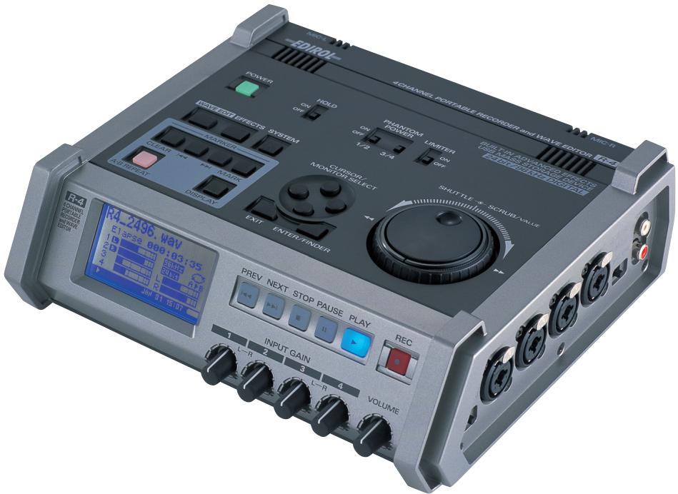
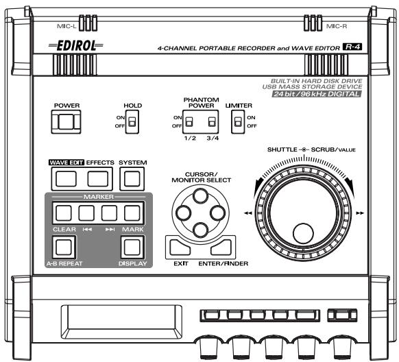
The R-4's controls and connectors
Top panel
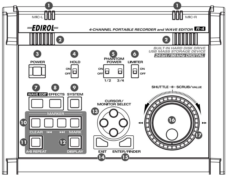
Internal mics [MIC-L, MIC-R]
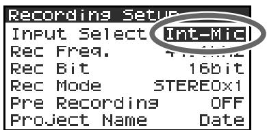
These are stereo mics built into the R-4. The audio entering MIC-L is recorded on the 1L channel, while audio picked up by MIC-R is recorded on the 1R channel. If you're recording via the internal mics, set the System Settings menu item Recording Setup to Int-Mic. For details, refer to "Recording from the internal mics" (p. 30).
- Don't connect anything to input jacks you're not using.
Internal speakers
These are built-in speakers for monitoring. If you want sound to be heard from the internal speakers, set the System Settings menu item Speaker to ON. For details, refer to "Playing back" (p. 34).
- No sound will be heard from the internal speakers if you've connected headphones to the Headphone jack ( ⑦ ). Nor will sound be heard from the internal speakers while recording or in recording-standby mode; this prevents acoustic feedback from occurring.
3 Power switch [POWER]
This turns the power on/off. To turn the power on or off, press and hold the power switch for about two seconds. The power switch is lit green when the power is on.
Don't turn the power off during recording or playback. Before you turn off the power, you must make sure that recording or playback is stopped.
- If you accidentally turn off the power during recording, the data that was being recorded will not be stored on the hard disk.
- The hard disk may be damaged if you turn off the power of the R-4 while data is being read from or written to the hard disk (such as during recording or playback). You must also be careful not to turn off the power while data is being transferred between the hard disk and the CompactFlash card.
- Never turn off the power while the R-4's display indicates Now Connecting... or Now Processing! Doing so will cause the R-4 to become unstable, and could even damage the internal hard disk.
![EDIROL R-4 - Power switch [POWER] - 1](/content/2019/11/174381/images/147bb3a055c08e0b88f60826cc1c026fa8a41f23ea467ca331b4f14576107933.jpg)
Hold switch [HOLD]
By selecting the HOLD ON position, you can disable the panel buttons so that unwanted operations will not occur if a button is pressed accidentally.
However, even if this switch is set to HOLD ON, the phantom power switches, limiter switch, input level select switches, Input level knobs, and Monitor level knob will still be operable.
5 Phantom power switches [PHANTOM POWER]
These switch the phantom power on/off for the XLR type connectors of the combo input jacks located on the right panel. Since separate switches are provided for channels 1/2 and channels 3/4, you can turn phantom power on/off separately for these channels.
- Always turn the phantom power off when connecting any device other than condenser microphones that require phantom power. You risk causing damage if you mistakenly supply phantom power to dynamic microphones, audio playback devices, or other devices that don't require such power. Be sure to check the specifications of any microphone you intend to use by referring to the manual that came with it.
This instrument's phantom power: 48 V DC, 8 mA Max (total of all channels must be 25 mA or less)
![EDIROL R-4 - Phantom power switches [PHANTOM POWER] - 1](/content/2019/11/174381/images/afa27cb68386b7637d9a5fd6c7681f94527c0740c7075f8f8eedf457d1ee48c6.jpg)
Limiter switch [LIMITER]
This is an on/off switch for an input level limiter in the analog circuitry.
When the input level is too high, the limiter compresses the input level appropriately to prevent distortion. The limiter switch turns limiting on/off for all channels 1-4 together. However, the input level is detected separately for each channel. You cannot turn the limiter on/off separately for each channel.
Wave edit button [WAVE EDIT]
This button takes you to Wave Edit mode, where you can edit the waveform using operations such as Trim, Divide, Combine, and Merge. For details, refer to "Editing" (p. 48).
You won't be able to enter Wave Edit mode during playback or recording, or if the R-4's hard disk contains no files that the R-4 can handle.
WAV files are the only type of files that the R-4 can handle.
Effect button [EFFECTS]
This button takes you to Effect mode, where you can make effect settings.
For details, refer to "Effects setting" (p. 55).
System button [SYSTEM]
This button takes you to a mode where you can make various settings for the R-4.
For details, refer to "System settings" (p. 60).
10 Marker [MARKER]
Clear button [CLEAR]
This button deletes a marker you assigned using the Mark button. Markers will be deleted successively, starting at the marker located immediately before the current location.
按钮
This button moves you to the marker that is immediately before the current location (the previous marker).
▶按钮
This button moves you to the marker that is immediately after the current location (the next marker).
Mark button [MARK]
By pressing this button you can assign a marker to a desired location in the project file. Markers are numbered sequentially starting at the beginning of the project.
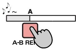
1 A-B Repeat button [A-B REPEAT]
This button lets you repeatedly play back the region between two points (A and B) in the project. Simply assign marker A and marker B while the project is playing, and playback will repeat between markers A and B.
- During playback, press the A-B Repeat button once.
That point becomes the beginning (marker A) of repeat playback.
![EDIROL R-4 - A-B Repeat button [A-B REPEAT] - 1](/content/2019/11/174381/images/82c8fb717a34582cf5e68448241121576d046d17a56845456242606d9fd3374b.jpg)
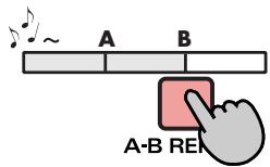
- Press the A-B Repeat button once again. That point will be the end (marker B) of repeat playback.
![EDIROL R-4 - A-B Repeat button [A-B REPEAT] - 2](/content/2019/11/174381/images/c94b6195d360a6b185ecbeafc951fb401816d1430a3a134f3dedcf2bc2580a2b.jpg)
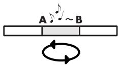
The region you specified in steps 1 and 2 will play repeatedly. To cancel repeat playback, press the A-B Repeat button once again.
![EDIROL R-4 - A-B Repeat button [A-B REPEAT] - 3](/content/2019/11/174381/images/146e838b889de1bfd965dae0718058ce421e854e2d2ee1288b9f37f0b0459673.jpg)
Display button [DISPLAY]
This button switches the contents of the R-4's display.
For details, refer to "Display" (p. 18).
![EDIROL R-4 - Display button [DISPLAY] - 1](/content/2019/11/174381/images/e042d7f2022082e326559ffac392241b9cd14a8c0a4adffd6283b58ba2aa6cc2.jpg)
Cursor/Monitor Select buttons [CURSOR/MONITOR SELECT]
Use these buttons to select items shown in the display. When you're in the main screen, you can press the up/down buttons to select the channel that you want to monitor.
For details, refer to "Display" (p. 18).
Exit button [EXIT]
Use this button to return to the previous screen or to cancel an operation.
Enter/Finder button [ENTER/FINDER]
Use this button to confirm a setting or finalize a value. You can also press this when you want to use the Finder function. For more about the Finder function, refer to "The Finder screen" (p. 41).
16 Scrub dial [SCRUB/VALUE]
Use this dial to select among items for which settings are made, or to modify a value. While stopped or when playback is paused, you can turn the scrub dial to move the current location forward or backward.
17 Shuttle dial [SHUTTLE]
While the project is playing, turn this dial clockwise to play rapidly forward, or counterclockwise to play rapidly backward. When the project is stopped, this dial advances the time counter.
Front panel
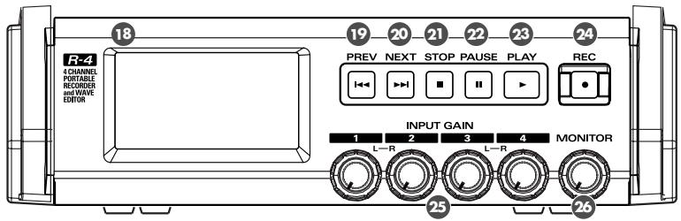
18 Display
This shows various information about the R-4's status.
For details, refer to "Display" (p. 18).
PREVB button [PREV]
Pressing the PREV button while a project is playing or stopped will take you to the beginning of the project (00:00:00). Pressing this button at the beginning of a project will take you to the preceding project.
You can also press and hold down this button to rewind. This is available both while playing and while stopped.
- If the system setting Player Setup parameter Play Mode is set to Single, you can't move to the previous or next project during playback.
NEXT button [NEXT]
Pressing the NEXT button will take you to the next project. You can also press and hold this button to fast-forward. This is available both while playing and while stopped.
- If the system setting Player Setup parameter Play Mode is set to Single, you can't move to the previous or next project during playback.
Stop button [STOP]
This button stops playback or recording. If you press the STOP button during playback, the counter will maintain the time at which you pressed the STOP button.
Pause button [PAUSE]
This button pauses playback or recording.
Play button [PLAY]
This button starts playback. The PLAY button is lit blue during playback.
During playback, you can press the PLAY button once again to play at double-speed. During double-speed playback, press the PLAY button once again to return to normal playback. During double-speed playback, the lower part of the display will indicate PLAY X2. Double-speed playback will change the pitch.
- If you want to turn off the double-speed playback feature, go to the System Settings menu and in Player Setup, turn X2 Play OFF. For details, refer to “2 Player Setup”(p. 62).
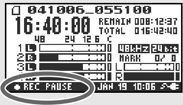
24 Record button [REC]
Recording will begin immediately when you press the REC button. The REC button is lit red during recording. If you hold down the PAUSE button and press the REC button, the REC button will blink red, and the R-4 enters recording-standby mode. Recording will begin when you then press the REC button or PAUSE button.
25 Input level knobs 1-4 [INPUT GAIN]
These knobs adjust the input level of combo input jacks 1-4 (39). Input levels of the internal mics (1) are adjusted by knob 1 (MIC-L) and knob 2 (MIC-R).
26 Monitor level knob [MONITOR]
This adjusts the output volume of the internal speakers (2) and the headphone jack (3).
You can't adjust the volume of the line output jacks (40). If you need to adjust the volume of the line output jacks, adjust the controls of the external speakers or playback system connected to the line output jacks.
Side panel (left)
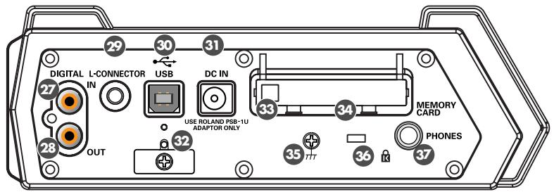
±b Digital input connector [DIGITAL IN]
If you want to record a digital signal, connect a coaxial-type cable to this connector. The digital input signal is recorded in stereo on channels 1L and 1R. If you want to record in monaural, you'll need to change the Rec Mode setting in the System Settings menu. For details, refer to "1 Recording Setup" (p. 60).
28 Digital output connector [DIGITAL OUT]
This connector outputs a digital signal. You can use a coaxial-type cable to connect this to a digital recording device such as a DAT or MD recorder. This connector provides the same audio signal as the line output jacks (40) and headphone jack (37), but in digital form.
29 L connector [L-CONNECTOR]
You can use a stereo mini-mini-plug LANC cable to connect this to a video device that is equipped with a LANC connector. When you begin recording on your video device, the R-4 will begin recording in tandem. When you stop recording on your video device, the R-4 will also stop recording. For details, refer to "Connecting a video device that has a LANC connector" (p. 74).
USB connector [USB]
Use the included USB cable to connect this to your computer. Projects recorded on the R-4 can be moved or copied to your computer. Files from your computer can also be moved or copied to the R-4's hard disk.
③ AC adaptor jack [DC IN]
Connect the included AC adaptor to this jack.
Cord hook
Use this to secure the AC adaptor cable.
33 Eject button
Press this when you want to remove the CompactFlash card inserted in the memory card slot.
Memory card slot [MEMORY CARD]
You can insert a CompactFlash card into this slot.
Projects you record on the R-4 can be copied to a CompactFlash card for backup or to transfer them to a computer.
The R-4 is able to use only TYPE 1 CompactFlash memory cards. Microdrive cards are not supported. For details on handling CompactFlash cards, refer to "Handling memory cards" (p. 70).
Grounding terminal
Depending on the circumstances of a particular setup, you may experience a discomforting sensation, or perceive that the surface feels brittle to the touch when you touch this device, microphones connected to it, or the metal portions of other objects. This is due to an infinitesimal electrical charge, which is absolutely harmless. However, if you are concerned about this, connect the ground terminal (see figure) with an external ground. When the unit is grounded, a slight hum may occur, depending on the particulars of your installation. If you are unsure of the connection method, contact the nearest Roland Service Center, or an authorized Roland distributor, as listed on the "Information" page.
Unsuitable places for connection
Water pipes (may result in shock or electrocution)
Gas pipes (may result in fire or explosion)
- Telephone-line ground or lightning rod (may be dangerous in the event of lightning)
Security Slot [K]
http://www.kensington.com/
⑦ Headphone jack [PHONES]
Connect a set of headphones to this jack. Use the monitor level knob (26) to adjust the volume. If you connect headphones, sound will not be heard from the internal speakers (2).
Side panel (right)
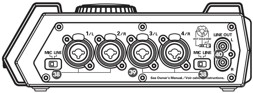
38 Input level select switches
Set these switches to either the MIC or LINE position depending on the type of device connected to channels 1/L and 2/R or channels 3/L and 4/R.
| MIC | If a mic is connected |
| LINE | If an audio device is connected via an analog connection |
39 Combo input jacks 1-4
These are analog audio input jacks compatible with mic preamps. They accept either XLR or 1/4'' phone plugs; you can use whichever is most convenient for the equipment you're connecting. Balanced or unbalanced signals can be connected.
You can use combo input jacks 1-4 as four channels of monaural input or as two stereo pairs, 1/2 and 3/4 . For details, refer to "1 Recording Setup" (p. 60).
- The XLR type jacks can provide 48 V phantom power, allowing you to connect phantom-powered condenser mics. In this case, turn on the phantom power switch (5).
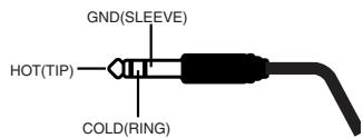
This instrument is equipped with balanced (XLR/TRS) type jacks. Wiring diagrams for these jacks are shown below. Make connections after first checking the wiring diagrams of other equipment you intend to connect.

Line output jacks [LINE OUT]
These jacks output an analog audio signal. You can use RCA phono cables to connect them to powered speakers, audio equipment, a mixer, etc. These jacks output the same signal as the digital output connector (29) and the headphone jack (37).
The nominal output level is fixed at -10 dBV, and the volume of these jacks cannot be adjusted.
Bottom panel
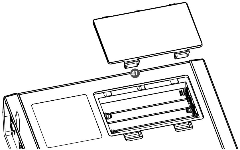
4 Battery compartment
Install batteries here if you want to operate the R-4 on battery power.
The orientation in which you must insert the batteries is shown on the side of the battery compartment.
Be sure to observe the correct polarity when installing the batteries.
If you're using the AC adaptor, there's no need to install batteries.
Make sure to switch off the R-4's power before you change from AC adaptor operation to battery operation, or vice versa.
For details, refer to "Installing batteries and turning the power on" (p. 25).
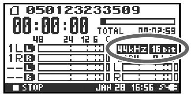
Display
While playing or stopped
The main screen
The R-4's main screen provides information about the project and the operational status of the R-4. You can press the [DISPLAY] button to switch the contents of the display.
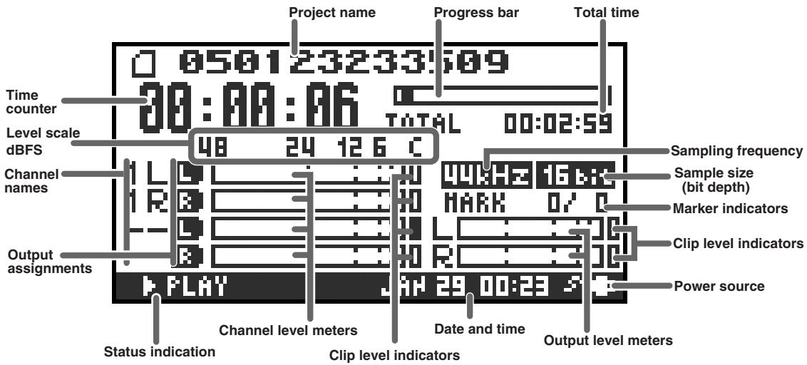
| Project name | Indicates the name of the project. If you copy WAV files from your computer via USB to the R-4's internal hard disk, this will show the file name. File names containing double-byte characters (e.g., Japanese) will not be displayed correctly, but they can be played. |
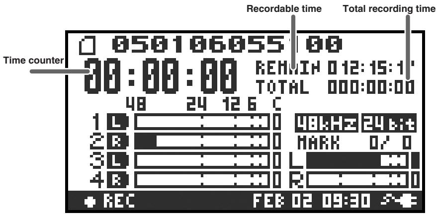
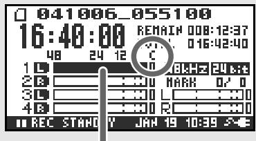
| Time counter | Indicates the time that has elapsed from the beginning of the project to the current location. Indicated in terms of hours: minutes: seconds. |
| Progress bar | Indicates the current playback location relative to the entire project. |
| Total time | Indicates the total time of the entire project. |
| Level scale | Shows the audio level of each channel in real time. The markings are relative to 0 dBFS (Full Scale) of the digital signal. For example, 12 means -12 dBFS. C is clipping level (0 dBFS). |
| Clip level indicators | |
| Channel level meters | |
| Channel names | This area shows up to four channel names. If you're using one stereo channel, this will indicate 1L and 1R. If you're using two stereo channels, this will indicate 1L, 1R, 2L, 2R. For a monaural project, this area will show 1, 2, 3, and 4 according to the number of channels. |
| Output assignments | These show how the audio of each channel is assigned to the L/R output channels. L means that the audio is assigned to the left channel, R to the right channel, and LR to both left and right channels. Channels for which no indication appears will not be output. When you're in the main screen, you can press the [CURSOR] up/down buttons to select the channel that you want to monitor. The output is sent to the PHONES jack, line output jacks, and digital output connector. |
| Sampling frequency | Indicates the sampling frequency and sample size (bit depth) of the currently selected project. |
| Sample size | |
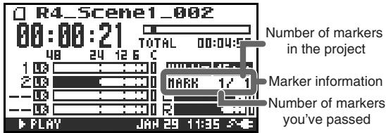
| Marker indicators | The number at the left indicates the marker located immediately before the current time counter value. The number at the right indicates the total number of markers assigned in the currently selected project. |
| Output level meters | These are the output level meters. They show the final output levels of the L and R channels, to which the various channels have been mixed. You can use the monitor level sliders of the mixer screen to adjust the level of each channel. From the left, the level meter is calibrated at -36, -24, -12, and -6 dBFS. |
| Clip level indicators | |
| Power source | Indicates how power is being supplied to the R-4. The plug icon is shown if power is being supplied by the AC adaptor, and the battery icon is shown if power is being supplied by batteries. |
In the main screen, you can press the [DISPLAY] button to switch the progress bar area so it shows the remaining project time (REMAIN).
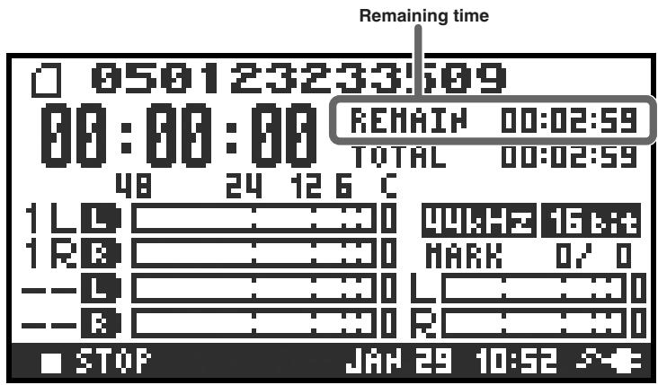
| Remaining time | During playback, this indicates the remaining time from the current location to the end of the project. |
The mixer screen
From the main screen, press the [DISPLAY] button twice to move to the Mixer screen. This screen lets you adjust the volume balance for monitoring.
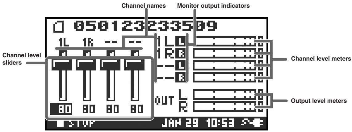
| Channel level sliders | Use these to adjust the playback level of each channel. Use the left/right [CURSOR/FINDER] buttons to select a slider, and turn the [SCRUB/VALUE] dial to adjust the value. Each slider provides adjustment within the range 0–120. The default value is 100. * The settings are not stored in the project; they are remembered by the R-4 itself. When you turn off the power, the settings will revert to their default values. * These settings do not affect the recording levels. |
While recording
The main screen
The R-4's main screen provides information about the project and the operational status of the R-4. You can press the [DISPLAY] button to switch the contents of the display.
| Time counter | Indicates the elapsed time from the beginning of the project you're recording until the current location. Indicated in terms of hours: minutes: seconds. |
| Recordable time | During recording, this indicates the remaining time that recording to the hard disk can take place. The remaining time will depend on the sampling frequency (Sample Freq.), sample size (Rec Bit), and recording mode (Rec Mode) settings. The indication shows how much longer you can record with the current settings. |
| Total recording time | Indicates the total time from the beginning of recording to the current location. * Even if you record continuously, another new project will be created automatically when the project reaches 2 GB in size, and recording will continue. Even for a recording that spans multiple projects in this way, the elapsed time since you first pressed the [REC] (record) button will be shown here. |
- For an explanation of the other indications, refer to "While playing or stopped" (p. 18).
From the main screen, you can press the [DISPLAY] button to make the recordable time area show the remaining hard disk capacity instead.
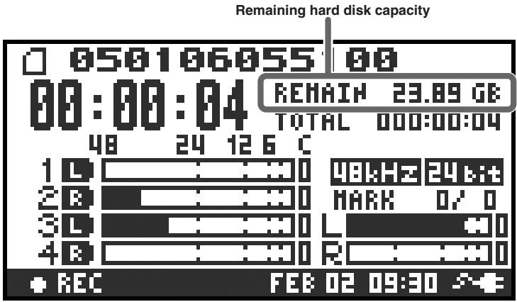
| Remaining hard disk capacity | Indicates the remaining free capacity on the internal hard disk. |
What is a project?
On the R-4, the data that you record and play back is handled as "projects." On the hard disk, each project actually consists of a folder with one or more files, in the structure shown below.
If you connect the R-4 to your computer, you'll be able to see how these folders and files are organized. However, if you change, delete, or rename the files within a project, the R-4 may be unable to play back that project. Please use caution.
In the system settings, the Recording Setup parameter Rec Mode (p. 61) lets you specify the type of project you want to record.
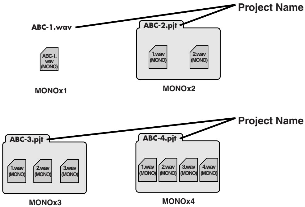
Monaural projects
| Type | Structure |
| MONOx1 | If there is only one channel, a monaural WAV file will be created with a name consisting of the project name plus an extension of .wav. |
| MONOx2 | If there are 2–4 channels, a folder will be created with a name consisting of the project name plus an extension of .pjt, and within that folder will be created monaural WAV files with names consisting of the channel number plus an extension of .wav. |
| MONOx3 | |
| MONOx4 |
Stereo projects
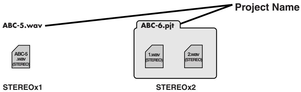
| Type | Structure |
| STEREOx1 | If there is only one channel, a stereo WAV file will be created with a name consisting of the project name plus an extension of .wav. |
| STEREOx2 | If there are two channels, a folder will be created with a name consisting of the project name plus an extension of .pjt, and within that folder will be created stereo WAV files with names consisting of the channel number plus an extension of .wav. |
Four-channel projects
| Type | Structure |
| 4CH | A four-channel WAV file will be created with a name consisting of the project name plus an extension of .wav. |
ABC-7.wav——Project Name

4CH
- If you want to load such files into your computer, make sure that your waveform editing software supports four-channel files.
Limitations on file size
The R-4 can handle files up to 2 GB in size. If the file size reaches 2 GB during recording, the file will be closed. Then, a new file will be created and recording will continue. When you finish recording, these files will appear as separate projects.
About BWF
Each WAV file within a project is in BWF format. In addition to the conventional WAV data, the file contains information about the recording time, recorder (EDIROL R-4), and marker data. Of course, these files can be loaded into players or waveform editing software in the same way as conventional WAV files.
Caution when copying files from your computer
Please note the following cautions when copying files from your computer into the R-4's internal hard disk.
- The R-4 can only record linear PCM WAV files at sampling frequencies of 44.1, 48, or 96kHz and bit depths of 16 or 24 bits. It cannot play back any other type of file.
- File names and folder names containing double-byte characters (e.g., Japanese) will not be displayed correctly.
- Any files other than WAV files cannot be recognized by the R-4, and will be ignored.
- Files beginning with ". ." (dot) will be ignored.
- You must not copy files larger than 2 GB into the R-4's internal hard disk. Doing so will make the R-4's operation unstable, and in the worst case might even damage the files in the internal hard disk.
Basic connection examples
Before you make connections to other equipment, turn down the volume of all your equipment and turn off the power to prevent malfunctions or speaker damage.
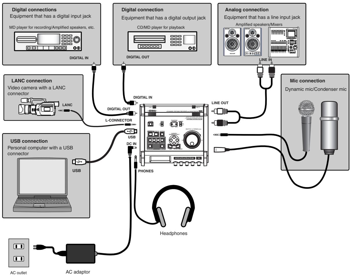
For more about connections, refer to "Recording" (p. 27) and "Playing back" (p. 34).
Connecting the AC adaptor and turning the power on
- After you've made connections correctly, you must turn on the power using the steps below. If you don't follow the correct order, you may cause malfunctions or damage your speakers.
- Due to a circuitry protection feature, this unit requires a few moments after power-up before it is ready for normal operation.
- If you connect the AC adaptor when batteries are installed, the power will be supplied from the AC adaptor.
Turning the power on
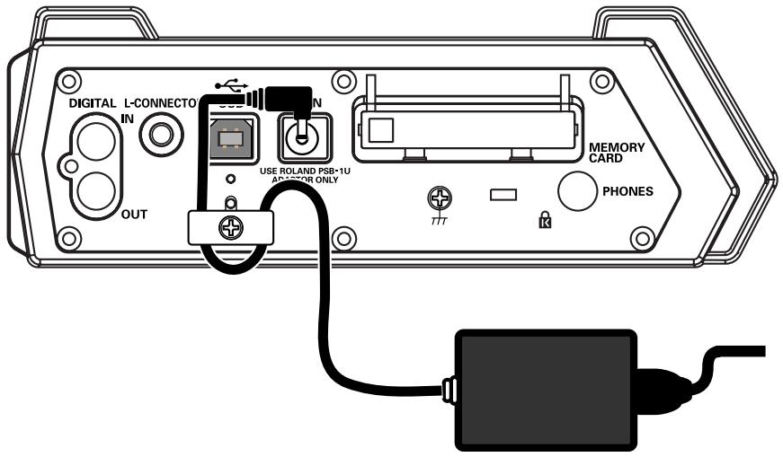
1 Connect the DC plug of the AC adaptor to the AC adaptor jack located on the left side panel of the R-4.
- Use only the included AC adaptor.
2 Plug the AC adaptor into an AC power outlet.
- To prevent the inadvertent disruption of power to your unit (should the plug be pulled out accidentally), and to avoid applying undue stress to the AC adaptor jack, anchor the power cord using the cord hook, as shown in the illustration.
3 To turn the power on, press and hold the R-4's [POWER] switch for about two seconds.
Wait until the main screen appears.
Turning the power off
1 From the main screen, press and hold the R-4's [POWER] switch for about two seconds to turn the power off.
- If you disconnect or reconnect the AC adaptor, the power will turn off even if batteries are installed. Please turn off the power on the R-4 itself before you change between AC adaptor power and battery power.
Installing batteries and turning the power on
Types of batteries you can use
AA alkaline batteries (LR6)
AA nickel metal-hydride (HR15/51)
(The R-4 cannot recharge nickel metal-hydride batteries. You'll need to use a separate charger.)
- You must set the R-4's System Settings menu item "5 System Setup" (p. 63) to specify the type of batteries you've installed. The R-4 will not operate correctly if you've specified a battery type that does not match the batteries you've actually installed.
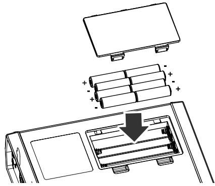
1 Make sure that the R-4 is turned off, and disconnect the AC adaptor from the AC adaptor jack.
2 Detach the battery cover from the bottom panel of the R-4.
- When turning the unit upside-down, handle with care to avoid dropping it, or allowing it to fall or tip over.
3 Insert eight AA batteries into the battery compartment, making sure to observe the correct polarity (+ and - symbols).
4 Replace the battery cover.
5 Turn on the R-4.
6 Press the [SYSTEM] button.
7 Use the [CURSOR] up/down buttons to select 5 System Setup.
Press the [ENTER] button.
9 Using the [SCRUB/VALUE] dial, set the Battery Type to Alkaline if you've installed alkaline batteries, or to Ni-MH if you've installed nickel metal-hydride batteries. The setting is activated as soon as you select it.
10 When you've finished making settings, press the [EXIT] button. You're returned to the previous screen.
11 When you're back in the System Menu screen, press the [EXIT] button once again.
Although the indication [ENTER] will be blinking in the display, if you don't need to make additional settings, press the [EXIT] button to return to the main screen.
Caution when using the R-4 on battery power
- If you operate on battery power for an extended time, the batteries will become hot. Be careful not to burn yourself.
- We recommend that you use alkaline batteries, which have a longer life.
- Don't mix new batteries with used batteries, and don't mix batteries of differing types.
- If you won't be using the R-4 for an extended time, we recommend that you remove the batteries to prevent leakage or other accidents.
- When using a USB cable to connect the R-4 to your computer, you must use the AC adaptor to prevent the loss of power while the connection is active.
Battery status indication
If you're using the R-4 on battery power, a battery icon is shown in the lower right of the display. As the battery runs down, the battery icon will change as follows.
| Remaining amount | Display | |
| Level 4 (sufficient) | ☐050123233509☐8:88:88☐70☐126C☐126C☐8:88:88☐126C☐126C☐8:88:88☐126C☐126C☐8:88:88☐126C☐126C☐8:88:88☐126C☐126C☐8:88:88☐126C☐126C☐8:88:88☐126C☐126 | |
| Level 3 | ☐050123233509☐8:88:88☐70☐126C☐126C☐126C☐8:88:88☐126C☐126C☐8:88:88☐126C☐126C☐8:88:88☐126C☐126C☐8:88:88☐126C☐126C☐8:88:88☐126C☐126 C☐126C☐126C☐8:88:88☐126C☐126C☐8:88:88☐126C☐126C☐8:88:88☐126C☐126C☐8:88:88☐126C☐126C☐8:88:88☐126C☐126 | ☐050123233509☐8:88:88☐70☐126C☐126C☐126C☐8:88:88☐126C☐126C☐8:88:88☐126C☐126C☐8:88:88☐126C☐126C☐8:88:88☐126C☐126C☐8:88:88☐126C☐126C☐8:88:88☐126C☐126C☐8:88:88☐126C☐126C☐8:88:88☐126C☐126C☐8:88:88☐126C☐1 |
| Level 2 | ☐050123233509☐8:88:88☐70☐126C☐126C☐126C☐126C☐126C☐126C☐126C☐126C☐126C☐126C☐126C☐126C☐126C☐126C☐126C☐126C☐126C☐126C☐126C☐126C☐126 C☐126C☐126C☐126C☐126C☐126C☐126C☐126C☐126C☐126C☐126C☐126C☐126C☐126C☐126C☐126C☐126C☐126C☐126C☐126C☐126 | ☐050123233509☐8:88:88☐70☐126C☐126C☐126C☐126C☐126C☐126C☐126C☐126C☐126C☐126C☐126C☐126C☐126C☐126C☐126 C☐126C☐126C☐126C☐126C☐126 C☐126C☐126C☐126C☐126C☐126C☐126C☐126C☐126C☐126C☐126C☐126C☐126C☐126C☐126C☐126 C☐126C☐126C☐126C☐126C☐126 |
| Level 1 | ☐050123233509☐8:88:88☐70☐126C☐126C☐126C☐126C☐126C☐126C☐126C☐126C☐126C☐126C☐126C☐126C☐126C☐126C☐126 | ☐050123233509☐8:88:88☐70 ☐☐126C☐126C☐126C☐126C☐126C☐126C☐126C☐126C☐126C☐126C☐126C☐126C☐126C☐126C☐126C☐126C☐126C☐126C☐126C☐126 |
| Level 0 (little remaining) | ☐050123233509☐8:88:88☐70☐126C☐126C☐126C☐126C☐126C☐126C☐126C☐126C☐126C☐126C☐126C☐126C☐126C☐126C☐126 |
When the battery reaches Level 0, the message shown will appear. Replace the batteries as soon as possible.
If you continue using the R-4 when the batteries have run low, the screen shown here will appear, and then the power will automatically turn off shortly thereafter.

Battery life
(When using alkaline batteries, 44.1 kHz, 16-bit, stereo, phantom power off)
| Continuous playback | approximately 3.5 hours |
| Continuous recording | approximately 2 hours |
- The values for battery life shown above are only approximate; they will vary depending on your system and conditions of use.
- The life of the battery will be shortened if you leave the display backlighting turned on or if you make heavy use of effects. There is a System setting that allows you to specify the length of time that the backlight is to remain on. For details, refer to "4 LCD Setup" (p. 62).
Recording from a connected mic
Here's how to record an audio source from a mic connected to the R-4's combo input jack.
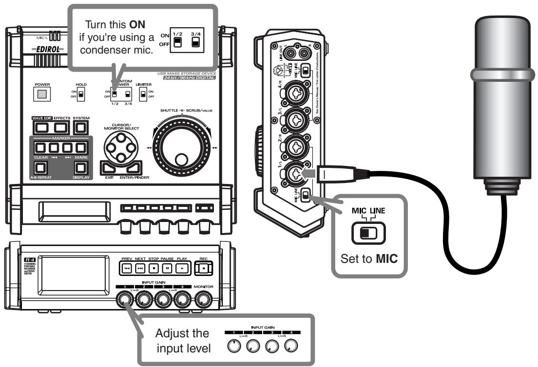
- Connections
Connect your mic to the combo input jack.
If you're monitoring through external speakers, acoustic feedback (a screech or whine) may occur, depending on the position of the mic relative to the speakers. If this occurs, take the following actions.
- Point the mic in a different direction
- Move the mic away from the speakers
- Lower the monitoring volume
- Input level select switch
Set this to the MIC position.
- Phantom power switch
If you've connected a phantom-powered condenser mic, turn this ON.
- System settings
Press the R-4's [SYSTEM] button.
In 1 Recording Setup, set Input Select to Analog.
Set the other items in 1 Recording Setup as appropriate for the recording you want to make.
- For more about system settings, refer to "System settings" (p. 60).
- Limiter
Turn this ON if you want to prevent unexpectedly loud sounds or strong attacks from producing clipping noise.
The limiter threshold is -10 dB relative to digital full scale, and the compression ratio is 1:3.
- Input level knobs
These knobs adjust the input levels.
If you're recording in stereo, these knobs control the following signals.
| Channel 1 | STEREO 1 L-channel | INPUT GAIN 1 knob |
| Channel 2 | STEREO 1 R-channel | INPUT GAIN 2 knob |
| Channel 3 | STEREO 2 L-channel | INPUT GAIN 3 knob |
| Channel 4 | STEREO 2 R-channel | INPUT GAIN 4 knob |
Adjusting the input level
- Hold down the [PAUSE] button and press the [REC] (record) button.
The R-4 will enter recording-standby mode. In recording-standby mode, the [REC] (record) button will blink, and the display will indicate REC STANDBY. - Play sound into the microphone at the actual volume that you expect to record.
- Gradually turn the input level knob toward the right.
-
Adjust the level so that the level meter shown in the display reaches a point slightly before C (clip level). If the recording level is too low, quiet sounds will not be recorded. If the recording level is too high, soft sounds will be distorted, producing a crackling noise in the recording.
-
The level meter indicates the clip level (C) at 0 dBFS (FS = full scale). For example, 12 indicates -12 dBFS.
level meter (dBFS)
- Record button [REC]
If you want to begin recording immediately, press the [REC] (record) button. Recording will begin.
Recording-standby
If you want to put the R-4 in recording-standby mode so that you can prepare for recording, hold down the [PAUSE] button and press the [REC] (record) button.
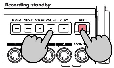
In recording-standby mode, the [REC] (record) button will blink and the display will indicate REC PAUSE.
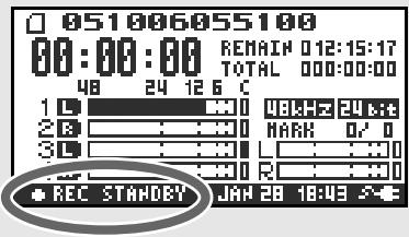
Recording will begin immediately when you press the [REC] (record) button or the [PAUSE] button in recording-standby mode or while paused.
Other settings
If you want to monitor the sound that's being recorded, connect headphones to the PHONES jack and use the monitor level knob to adjust the volume.
Adjusting the monitor level knob won't affect the level of the sound that's actually being recorded.
To play back the recorded sound, refer to "Playing back" (p. 34).
Caution regarding placement and handling while recording
The internal hard disk is a precision device. If you subject the hard disk to impacts such as the following, the data may not be read or written successfully, causing recording or playback to be unsuccessful. In the worst case, irreparable damage may occur.
Please be careful not to subject the R-4 to strong impact or continued vibration while using it.
The following actions will cause malfunctions
- Subjecting the unit to impact, such as dropping it from a table onto a hard floor.
- Subjecting the unit to continuous vibration, such as by leaving it on an uncushioned surface like the floor of a moving automobile.
Recording from the internal mics
Here's how to record an audio source via the R-4's internal mics.
- Phantom power switch
Turn this OFF.
- System settings
Press the R-4's [SYSTEM] button.
In 1 Recording Setup, set Input Select to Int-Mic.
Set the other items in 1 Recording Setup as appropriate for the recording you want to make.
- For more about system settings, refer to "System settings" (p. 60).
- Input level knobs
Adjust the input level.
Refer to "Adjusting the input level" (p. 28).
Input levels of the internal mics are adjusted by knob 1 (MIC-L) and knob 2 (MIC-R).
- Record button [REC]
Press the [REC] (record) button to begin recording.
For details on recording-standby, refer to "Recording-standby" (p. 28).
Other settings
If you want to monitor the sound that's being recorded, connect headphones to the PHONES jack and use the monitor level knob to adjust the volume.
Adjusting the monitor level knob won't affect the level of the sound that's actually being recorded.
To play back the recorded sound, refer to "Playing back" (p. 34).
Recording digital audio from a digital device
Here's how to record from a digital device connected to the R-4's digital input jack.
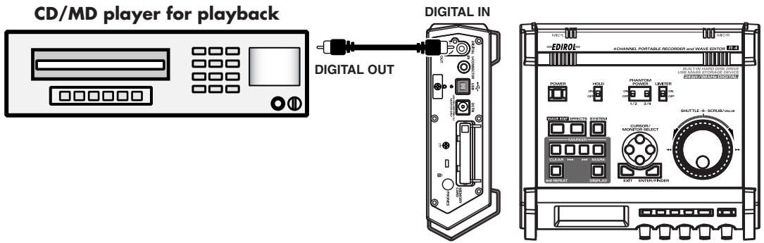
- Connections
Connect your digital device to the digital input jack. You'll need a separately available coaxial-type cable to connect your device to the R-4's digital input jack.
- System settings
Press the R-4's [SYSTEM] button.
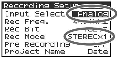
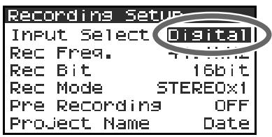
In 1 Recording Setup, set Input Select to Digital.
Set the other items in 1 Recording Setup as appropriate for the recording you want to make.
- For more about system settings, refer to "System settings" (p. 60).
- The R-4 is not able to synchronize to the clock signal of the digital input connector. Regardless of the sampling frequency that is being input, the incoming digital audio data will be converted to the sampling frequency (Rec Freq.) and sample size (Rec Bit) that are specified in Recording Setup.
- Record button [REC]
Press the [REC] (record) button to begin recording.
For details on recording-standby, refer to "Recording-standby" (p. 28).
- Other settings
If you want to monitor the sound that's being recorded, connect headphones to the PHONES jack and use the monitor level knob to adjust the volume.
Adjusting the monitor level knob won't affect the level of the sound that's actually being recorded.
- If you're recording the digital input, you can't use the input level knob to adjust the input level.
To play back the recorded sound, refer to "Playing back" (p. 34).
Recording analog audio
Here's how to record from an audio device connected to the R-4's combo input jacks.
Audio playback system
(CD player, record player, etc.)
- Connections
Connect your audio device to the combo input jacks.
You'll need to use phone-jack audio cables (sold separately).
- When connection cables with resistors are used, the volume level of equipment connected to the combo input jacks may be low. If this happens, use connection cables that do not contain resistors, such as those from the Roland PCS series.
- Input level select switch
Set to LINE.
- Phantom power switch
Turn this OFF.
- System settings
Press the R-4's [SYSTEM] button.
In 1 Recording Setup, set Input Select to Analog.
Set the Rec Mode to STEREOx1.
Set the other items in 1 Recording Setup as appropriate for the recording you want to make.
- For more about system settings, refer to "System settings" (p. 60).
- Input level knobs
Adjust the input level 1 (L) and 2 (R) knobs. If there are channels to which you have not connected anything, turn their input level knobs to the minimum position.
Refer to "Adjusting the input level" (p. 28).
- Record button [REC]
Press the [REC] (record) button to begin recording.
For details on recording-standby, refer to "Recording-standby" (p. 28).
- Limiter
Turn this OFF if you're recording an audio source whose levels have already been regularized (in contrast to a live audio source whose levels might change unpredictably), or if you have already checked the maximum volume levels that are going to occur.
Turn this ON if you need to prevent clipping (distortion) that might be caused by unexpectedly loud volumes or strong attacks.
Other settings
If you want to monitor the sound that's being recorded, connect headphones to the PHONES jack and use the monitor level knob to adjust the volume.
Adjusting the monitor level knob won't affect the level of the sound that's actually being recorded.
To play back the recorded sound, refer to "Playing back" (p. 34).
This section explains various procedures and methods by which you can play back the projects in the R-4's internal hard disk and the audio material you recorded on the R-4. \Make the correct settings and connections before you play anything back.
- Connections before playback. (p. 34)
- Settings before playback (p. 36)
- Playing back. (p. 38)
Connections before playback
Connecting headphones
Headphones are a convenient way to monitor while you're recording or immediately after recording.
- Turn the [MONITOR] level knob all the way to the left to minimize the volume.
- Connect your headphones to the PHONES jack.
- Slowly turn the [MONITOR] level knob toward the right to adjust the volume.
Connecting amplified speakers
Here's how to connect amplified speakers that have line input jacks or a digital input jack.
- Switch off the power on the R-4.
- Minimize the volume of the speakers you want to connect, and turn off their power.
- Depending on the type of speakers you are using, connect the R-4's [LINE OUT] line input jacks or [DIGITAL OUT] digital output jack to your amplified speakers.
- Switch on the R-4's power.
-
Next, switch on your speakers, and gradually increase the volume to the desired level.
-
The R-4 does not provide a way to adjust the volume of the audio that is output from its line output jacks.
Connecting a mixer or other analog device (analog connection: line output jacks)
Here's how to connect a mixer or other audio device that has line input jacks.
- Switch off the power on the R-4.
- Minimize the volume of the mixer or other device you're going to connect.
- Connect the R-4's [LINE OUT] line input jacks to your mixer. You'll need separately available audio cables (not included) for connecting to the R-4's line output jacks.
- Switch on the R-4's power.
- Next, switch on your mixer, and gradually increase the volume to the desired level.
- The R-4 does not provide a way to adjust the volume of the audio that is output from its line output jacks.
Connecting an MD recorder or other digital recording device (digital connection: digital output connector)
You can connect an MD recorder or other device that has a digital input connector, and use it to record the sound played back by the R-4.
The sampling frequency of the project you're playing back will be the sampling frequency of the audio that's output from the digital output connector.
- Switch off the power on the R-4.
- Switch off your MD recorder.
-
Connect the R-4's [DIGITAL OUT] jack to the digital input jack of your MD recorder.
-
You'll need a separately available coaxial-type cable (not included) for connecting the R-4's digital output jack to your digital device.
-
Switch on the R-4's power.
-
Next, switch on your MD recorder.
-
The R-4 does not provide a way to adjust the volume of the digital audio signal.
Settings before playback
Player Setup
Press the R-4's [SYSTEM] button.
The system menu screen appears in the display.
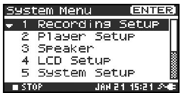
2 Use the [CURSOR] buttons to choose 2 Playing Setup, and press the [ENTER] button.
The Recording Setup screen appears.
3 Use the [SCRUB/VALUE] dial to choose the Play Mode value.
- The setting is applied as soon as you select it. You don't need to press the [ENTER] button.
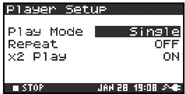
Make settings for the following items as well.
| Menu | Player Setup settings | Playback method |
| Play Mode | Single | Selects the playback mode. Only the selected project will play. |
| Sequential | The projects in the folder containing the currently selected project will play consecutively. | |
| Repeat | OFF, ON | Selects whether playback will repeat. If Play Mode is Single, only that project will play repeatedly. If it is Sequential, the projects in the folder containing the currently selected project will play consecutively, and then the projects in the same folder will again play consecutively from the beginning. |
| X2 Play | OFF, ON | This enables/disables the function that provides double-speed playback when you press the [PLAY] button a second time during playback (i.e., when you press [PLAY] twice). The indication PLAY X2 will appear in the lower part of the display. Normal playback will resume when you press the [PLAY] button once again. |
- For more about system settings, refer to "System settings" (p. 60).
Speaker
You can use the R-4's built-in speakers to monitor the sound without having to connect headphones or other equipment.

Press the R-4's [SYSTEM] button.
The system menu screen appears in the display.


Use the [CURSOR] buttons to choose 3 Speaker Switch, and press the [ENTER] button.
The Speaker screen appears.
| Speaker Switch setting | Output destination |
| ON | Internal speakers |
| Line output jacks | |
| Digital output jack | |
| OFF | Line output jacks |
| Digital output jack |

- You can't monitor via the internal speakers while recording. You'll need to monitor through headphones. Note that sound will not be output from the speakers if headphones are connected. If you want to use the internal speakers, you must disconnect the headphones.
- For more about system settings, refer to "System settings" (p. 60).
Playing back
Normal playback
After you've performed the steps described in "Connections before playback" (p. 34) and "Settings before playback" (p. 36), proceed as follows.
1 Select the project that you want to play.
In the main screen, press the [ENTER/FINDER] button. In the Finder screen that appears, use the up/ down [CURSOR] buttons and the [SCRUB] dial to select a project. For more about the Finder screen, refer to "The Finder screen" (p. 41).
Alternatively, you can use the front panel's [PREV] button or [NEXT] button to select the project you want to play. The projects are in alphabetical order.
2 Press the [PLAY] button.
The selected project will play.
3 Slowly raise the [MONITOR] level knob to the desired volume for listening.
- Projects with names beginning with ". ." are ignored, and will not be shown.
- The project name will not be displayed correctly if the project name contains double-byte characters (e.g., Japanese). To ensure that you can view the file name correctly, don't use double-byte characters in the filename.
- Projects whose filename extension is other than .pjt or .wav will be ignored, and will not be shown.
Mark
You can assign markers at desired locations in a project. Then you can use the button or
▶按钮 to move backward or forward to the location of a marker.
You can use the Mark function either while playing or while recording.
1
Use the [NEXT] button or the [SHUTTLE] dial to find the location at which you want to assign a marker.
Play, fast-forward, or rewind the project to the location at which you want to assign a marker.
2
Press the [MARK] button at the location at which you want to assign a marker.
You can assign markers while playing, recording, or stopped.
The display indicates the number of markers as shown at right. Marks are numbered sequentially starting at the beginning of the project.
You can assign up to 99 markers.
Repeat steps 1 and 2 to assign markers as desired.
3
When you've assigned one or more markers, proceed as follows.
You can use these operations either while playing or while stopped.

button
Moves to the marker immediately before the current location (previous marker).

button
Moves to the marker immediately following the current location (next marker).
CLEAR button
Deletes the marker you specified using the [Mark] buttons. Marks are deleted consecutively, starting with the marker immediately before the current location.
Repeat playback (A-B REPEAT)
You can repeatedly play back between two points (A-B) in the project. Simply assign points A and B during playback, and the playback will repeat between points A and B.
Play back the project.
During playback, press the [A-B REPEAT] button once. The [A-B REPEAT] button will blink, and that location will be remembered as the starting point (A) for repeat playback.
- If, after assigning point A, you press the STOP button before assigning point B, point A will be cleared.
Press the [A-B REPEAT] button once again. The [A-B REPEAT] button will change from blinking to solidly lit, and that location will be remembered as the end point (B) for repeat playback.
Playback will automatically repeat between the points you specified in steps 1 and 2.
To cancel repeat playback, press the [A-B REPEAT] button when points A and B have already been assigned. The [A-B REPEAT] button will go out, and repeat playback will be cancelled.
Please note
- If, after assigning point A, you press the STOP button before assigning point B, point A will be cleared.
- If the song plays all the way to the end after you've assigned point A, playback will repeat between point A and the end of the song.
- If you press the [STOP] button during repeat playback, playback will stop and the repeat region (A-B) settings will be cleared.
The R-4 saves projects as files on its internal hard disk. If there are numerous folders or projects within folders, you can use the Finder screen to select the project that you want to play. In this screen you can also perform operations such as deleting an unwanted project or copying a project to a CompactFlash card.
Finder functions
| No. | Menu | Operation | See |
| 1 | Select | Select and load a project. | p. 41 |
| 2 | Delete | Delete a project. | p. 42 |
| 3 | Rename | Rename a project. | p. 43 |
| 4 | Copy | Copy the selected project. | p. 44 |
| 5 | Move | Move the selected project to a different folder. | p. 45 |
| 6 | Make Folder | Create a new folder. | p. 46 |
Selecting a project (Select)

With project playback stopped and the main screen (p. 18) shown in the display, press the [ENTER/FINDER] button. The Finder screen shown in the illustration will appear.
Projects are shown in descending alphabetical order.


In the Finder screen, use the [CURSOR] up/down buttons or the [SCRUB] dial to select the desired project. Then press the [ENTER] button.
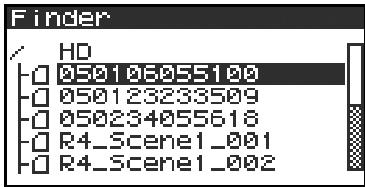

If the desired project is in a folder, the hard disk (HD), or the CompactFlash card (CF), you can press the [CURSOR] right button to move into the selected folder (i.e., move to a lower-level folder).
If you want to move back to the upper-level folder, press the [CURSOR] left button.

When the screen at right appears, use the [CURSOR] buttons to choose 1 Select.
The project will be selected, and you will return to the main screen.
Alternatively, with a project selected (step 2), you can press the [PLAY] button (instead of pressing the [ENTER] button) to play the selected project. You will return to the main screen when playback begins.
- Since you cannot directly play back projects from the CompactFlash card, you won't be able to select them. You will have to copy the desired project to the R-4's internal hard disk before you can select it.
Deleting a project (Delete)

With the main screen shown in the display, press the [ENTER/FINDER] button. The Finder screen shown in the illustration will appear.
Projects are shown in descending alphabetical order.


In the Finder screen, use the [CURSOR] up/down buttons or the [SCRUB] dial to select the project you want to delete. Then press the [ENTER] button.

If the desired project is in a folder, the hard disk (HD), or the CompactFlash card (CF), you can press the [CURSOR] right button to move into the selected folder (i.e., move to a lower-level folder). If you want to move back to the upper-level folder, press the [CURSOR] left button.
- If you want to select the CompactFlash card, select the hard disk (HD) and then press the [CURSOR] right button; the contents of the CompactFlash card will appear. However, this will not be displayed if no CompactFlash card is inserted.


When the screen shown in the illustration appears, use the [CURSOR] buttons to choose 2 Delete.

The screen shown in the illustration will appear. Press the [ENTER] button to execute the Delete operation.
- If you decide to cancel without executing, press the [EXIT] button before you press the [ENTER] button.
Don't turn off the power while a project is being deleted.
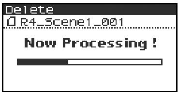
Renaming a project (Rename)

With the main screen shown in the display, press the [ENTER/FINDER] button. The Finder screen shown in the illustration will appear.
Projects are shown in descending alphabetical order.


In the Finder screen, use the [CURSOR] up/down buttons or the [SCRUB] dial to select the project you want to rename. Then press the [ENTER] button.


If the desired project is in a folder, the hard disk (HD),
or the CompactFlash card (CF), you can press the [CURSOR] right button to move into the selected folder (i.e., move to a lower-level folder). If you want to move back to the upper-level folder, press the [CURSOR] left button.
- If you want to select the CompactFlash card, select the hard disk (HD) and then press the [CURSOR] right button; the contents of the CompactFlash card will appear. However, this will not be displayed if no CompactFlash card is inserted.


When the screen shown in the illustration appears, use the [CURSOR] buttons to choose 3 Rename.
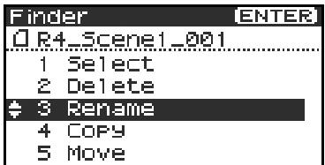

Use the [CURSOR] left/right buttons to move the cursor through the characters of the project name or folder name shown in the display. Place the cursor at the character that you want to change, and then use the [CURSOR] up/down buttons or the [SCRUB/VALUE] dial to change the character.
Use the [CLEAR] button to delete a character, or the [Mark] button to insert a character. Use these buttons to edit the name as desired.
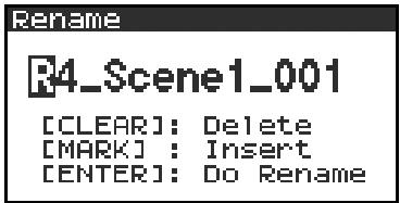
When you've finished editing the name, press the [ENTER] button.
- If you decide to cancel without renaming, press the [EXIT] button before you press the [ENTER] button.
Don't turn off the power while a project is being renamed.

Copying a project (Copy)

With the main screen shown in the display, press the [ENTER/FINDER] button. The Finder screen shown in the illustration will appear.
Projects are shown in descending alphabetical order.


In the Finder screen, use the [CURSOR] up/down buttons or the [SCRUB] dial to select the copy-source project (the project you want to copy). Then press the [ENTER] button.
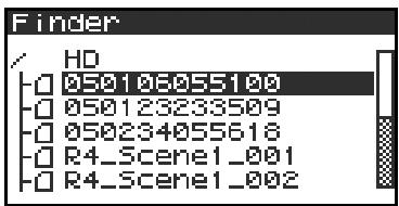

If the desired project is in a folder, the hard disk (HD),
or the CompactFlash card (CF), you can press the [CURSOR] right button to move into the selected folder (i.e., move to a lower-level folder).
If you want to move back to the upper-level folder, press the [CURSOR] left button.
- If you want to select the CompactFlash card, select the hard disk (HD) and then press the [CURSOR] right button; the contents of the CompactFlash card will appear. However, this will not be displayed if no CompactFlash card is inserted.


When the screen shown in the illustration appears, use the [CURSOR] buttons to choose 4 Copy.
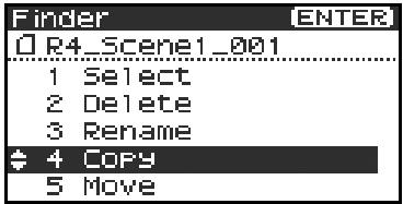

Use the [CURSOR] up/down buttons or the [SCRUB/VALUE] dial to select the copy-destination folder (the folder to which you want to copy the project). Then press the [ENTER] button to execute the Copy operation. As the copy destination, you may also select HD (hard disk) or CF (CompactFlash).
- If you decide to cancel without executing, press the [EXIT] button.
Don't turn off the power while a project is being copied.
- If the copy destination contains an identically named project, a number such as -1 or -2. will be appended to the name of the copied project.
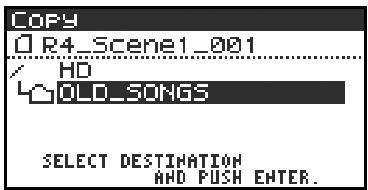
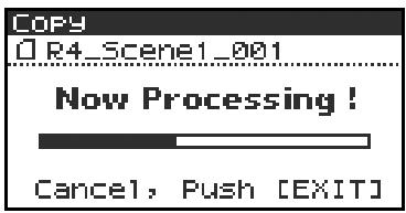
Moving a project (Move)
- You can't move a project between the hard disk and the CompactFlash card. If you need to do this, you can first copy the project, and then delete the copy-source project.

With the main screen shown in the display, press the [ENTER/FINDER] button. The Finder screen shown in the illustration will appear.
Projects are shown in descending alphabetical order.
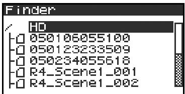

In the Finder screen, use the [CURSOR] up/down buttons or the [SCRUB] dial to select the project that you want to move. Then press the [ENTER] button.

If the desired project is in a folder, the hard disk (HD), or the CompactFlash card (CF), you can press the [CURSOR] right button to move into the selected folder (i.e., move to a lower-level folder).
If you want to move back to the upper-level folder, press the [CURSOR] left button.
- If you want to select the CompactFlash card, select the hard disk (HD) and then press the [CURSOR] right button; the contents of the CompactFlash card will appear. However, this will not be displayed if no CompactFlash card is inserted.


When the screen shown in the illustration appears, use the [CURSOR] buttons to choose 5 Move.

Use the [CURSOR] up/down buttons or the [SCRUB/VALUE] dial to select the destination folder (the folder to which you want to move the project). Then press the [ENTER] button to execute the Move operation. You may also select HD (hard disk) as the destination.
- If you decide to cancel without executing, press the [EXIT] button.
Don't turn off the power while a project is being moved.
Creating a new folder (Make Folder)

With the main screen shown in the display, press the [ENTER/FINDER] button. The Finder screen shown in the illustration will appear.
Projects are shown in descending alphabetical order.
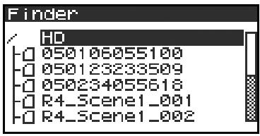

In the Finder screen, use the [CURSOR] up/down buttons or the [SCRUB] dial to select HD (hard disk) located at the top level.
Then press the [ENTER] button.
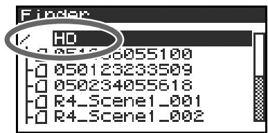

If the desired project is in a folder, the hard disk
(HD), or the CompactFlash card (CF), you can press the [CURSOR] right button to move into the selected folder (i.e., move to a lower-level folder).
If you want to move back to the upper-level folder, press the [CURSOR] left button.
- If you want to select the CompactFlash card, select the hard disk (HD) and then press the [CURSOR] right button; the contents of the CompactFlash card will appear. However, this will not be displayed if no CompactFlash card is inserted.


When the screen shown in the illustration appears, use the [CURSOR] buttons to choose 2 Make Folder.


When the screen shown in the illustration appears, press the [ENTER] button to confirm the operation.

Don't turn off the power while a folder is being created.


A folder named NewFolder will be created.
Projects are shown in alphabetical order, and folders are shown in alphabetical order after the projects.
Use the [CURSOR] up/down or the [SCRUB] dial to verify that the new folder was created.
If an identically named folder already exists, a number will be added to the name of the newly created folder; e.g., NewFolder-1, NewFolder-11, NewFolder-111, etc.
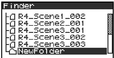
Projects you record using the R-4 can be edited directly on the R-4.
| No. | Editing command | Result | See |
| 1 | Trim | Specify two points in the waveform, extract the region, and create a new project using that region. | p. 48 |
| 2 | Divide | Specify one point in the waveform, and divide the project at that point. Two new projects will be created. | p. 50 |
| 3 | Combine | Append another project following the end of the currently selected project. The two files will be joined to create a single new file. | p. 52 |
| 4 | Merge | A project consisting of multiple files will be merged into a single channel. | p. 54 |
- Executing any of these editing commands will leave the original project file unchanged.
- There is no Undo function.
Editing procedure
Trim
This command extracts the region between the two points you specify in the waveform, and creates a new project using this extracted region.
You can perform playback, stop, or operate the scrub dial and shuttle dial even while using this command.
However, you cannot perform A-B Repeat or marker-related operations.
1
Press the R-4's [WAVE EDIT] button. The Wave Edit Menu screen appears in the display.
2
Use the [CURSOR] buttons to choose 1 Trim, and press the [ENTER] button.
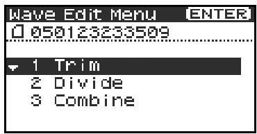
The editing screen shown at the right will appear.
Time axis zoom (1/1-1/65536)
Use the [CURSOR] left/right buttons to adjust this
Waveform level zoom (x1-x64)
Use the [CURSOR] up/down buttons to adjust this
- If you decide not to adjust the settings, press the [EXIT] button.
3
While playing or fast-forwarding, press the [ENTER] button when you reach the beginning (point 1) of the region you want to extract.
Alternatively, you can use the scrub dial or shuttle dial to specify the point instead of doing so during playback.
- The value of point [ ] is shown in terms of samples (data).

In the same way, move to the end (point 2) of the region you want to extract, and press the [ENTER] button.
- The value of point ② is shown in terms of samples (data).
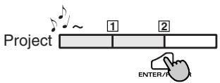

A screen asking you to confirm the specified points will appear.
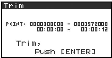
If you are satisfied with the points you specified, press the [ENTER] button to confirm the settings. If you decide to try again, you can press the [EXIT] button once and re-specified the end of the region (point 2). You can then press the [EXIT] button once again and re-specified the beginning of the region (point 1). Even when the screen shown at the right is displayed, you can halt execution by pressing the [EXIT] button.
- Don't turn off the power while a project is being saved or while processing is being performed.


The extracted region will be saved as a new project with the same name as the original project but with " -1" appended to it. The original project will remain unchanged.
For example, if the original project is named Project, the new project will be named Project-1.
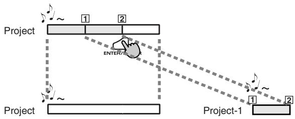

Media Full!
If the internal hard disk does not have enough space to save the project, a message of "Media Full!" will appear.
Divide
This command divides the project at the point you specify in the waveform. Two new projects will be created.
You can perform playback, stop, or operate the scrub dial and shuttle dial even while using this command.
However, you cannot perform A-B Repeat or marker-related operations.
Press the R-4's [WAVE EDIT] button. The Wave Edit Menu screen appears in the display.
2 Use the [CURSOR] buttons to choose 2 Divide, and press the [ENTER] button.
The editing screen shown at the right will appear.
Time axis zoom (1/1-1/65536)
Use the [CURSOR] left/right buttons to adjust this
Waveform level zoom (x1-x64)
Use the [CURSOR] up/down buttons to adjust this
- If you decide not to adjust the settings, press the [EXIT] button.
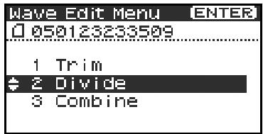
3 While playing or fast-forwarding, press the [ENTER] button when you reach the point at which you want to divide the project.
Alternatively, you can use the scrub dial or shuttle dial to specify the point instead of doing so during playback.
A screen asking you to confirm the specified point will appear.
To execute the Divide operation at the point you specified, press the [ENTER] button.
If you decide not to execute the Divide operation, press the [EXIT] button.
Even when the screen shown at the right is displayed, you can halt execution by pressing the [EXIT] button.

- Don't turn off the power while a project is being saved or while processing is being performed.
- It may take some time to save the project if it contains a large amount of data.

The divided project will be saved as two new projects with the same name as the original project but with " -1" and " -2" appended to the names. The original project will remain unchanged.
For example, if the original project is named Project, the new projects will be named Project-1 and Project-2.

Media Full!
If the internal hard disk does not have enough space to save the project, a message of "Media Full!" will appear.
Combine
This command appends another project (of the same format) onto the end of the currently selected project.
The two files will be joined to create a single new file.
You cannot perform playback, stop, or operate the scrub dial or shuttle dial while using this command.
1 Select the project (the "base project") to which you want to append another project.
In the main screen, use the [NEXT] button or [PREV] button to select the desired project. Alternatively, you can use the cursor buttons in the Finder screen.
Press the R-4's [WAVE EDIT] button. The display shows the Wave Edit Menu screen.
3 Use the [CURSOR] buttons to choose 3 Combine, and press the [ENTER] button.
The display shows an editing screen like the one at right.
- If you decide to cancel the operation, press the [EXIT] button.
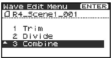
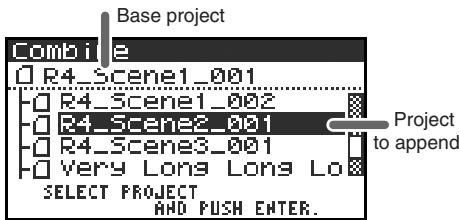
4 Use the [CURSOR] buttons to select the project that you want to append, and press the [ENTER] button.
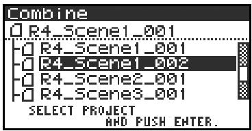
If you decide to cancel the operation, press the [EXIT] button. Even when the screen shown at right is displayed, you can halt execution by pressing the [EXIT] button.
- Don't turn off the power while a project is being saved or while processing is being performed.
- It may take some time to save the project if it contains a large amount of data.
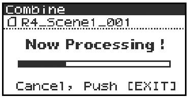

The "base project" and the "project to be appended" must have the same sampling frequency, sample size (bit depth), and number of channels.
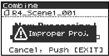
If you select a project that cannot be appended, the message shown here will appear.

The combined projects will be saved as a new project with the same name as the original project but with "-1" appended to it. The original project will remain unchanged. For example, if the original project is named Project, the new project will be named Project-1.
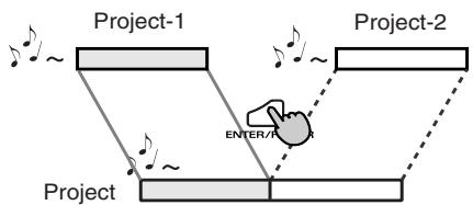

Media Full!
If the internal hard disk does not have enough space to save the project, a message of "Media Full!" will appear.
Merge
If the currently selected project consists of multiple files (MONO x2, MONO x3, MONO x4, STEREO x2), this command merges them into a single channel.
How Rec Mode will change
| Before Merge | After Merge |
| MONOx2 | |
| MONOx3 | MONOx1 |
| MONOx4 | |
| STEREOx2 | STREOx1 |
- Since MONO x1, STEREO x1, or 4 ch. projects cannot be merged, the Merge command will not appear in the menu if you've selected this type of project.
1
Press the R-4's [WAVE EDIT] button. The Wave Edit Menu screen will appear.
2
Use the [CURSOR] buttons to choose 4 Merge, and press the [ENTER] button.
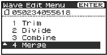
The editing screen shown at right will appear.
If you want to adjust the level (Mix Level) of the channels in the project, you can do so. Use the [CURSOR] up/down buttons or the [SCRUB] dial to specify the value.
For example, in a stereo two-channel project (STEREO x2), you might set the Mix Level to -6.0 dB so that the level of each channel will be lowered by 6 dB when they are merged.
- If you decide to cancel, press the [EXIT] button.
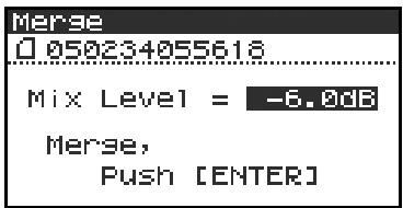
3
To execute, press the [ENTER] button.
If you decide not to use the Merge command, press the [EXIT] button.
Even when the screen shown at the right is displayed, you can halt execution by pressing the [EXIT] button.

- Don't turn off the power while a project is being saved or while processing is being performed.
- It may take some time to save the project if it contains a large amount of data.

Media Full!
If the internal hard disk does not have enough space to save the project, a message of "Media Full!" will appear.
The R-4 provides five types of effects. You can apply an effect to the incoming sound as it's being recorded, or you can apply an effect to the playback. You can also change the effect settings for each channel.
- Effects are not available when the R-4 is operating at 96 kHz.
Effect types provided on the R-4
| No. | Effect name | Effect |
| 0 | No Effect | No effect will be applied. Use this setting if you want to preserve the effect on/off setting of each channel, but don’t want an effect to be applied. |
| 1 | 3-Band EQ | Three-band equalizer. |
| 2 | Graphic EQ | You can adjust the gain of six fixed-frequency bands. |
| 3 | Noise Gate | This effect minimizes the noise that might be heard in silent regions, as well as low-frequency noise. |
| 4 | Enhancer | By adding a phase-shifted sound to the direct sound, this effect sharpens the definition of the sound and pushes it toward the foreground. |
| 5 | Comp&DeEsser | This cuts the sibilance that can be obtrusive in a vocal, making the sound smoother. It also reduces the difference between loud and soft sounds, making the level more consistent. A compressor evens out the level differences between loud and soft sounds. A de-esser reduces the unpleasant sibilance (exaggerated “s” sound) that is sometimes present in a vocal. |
If you apply an effect while recording, the volume and tone of the recorded sound will be different than the original sound.
Before applying an effect aggressively during recording, it's a good idea to monitor the sound through headphones in recording-standby mode to make sure that the sound is not clipping or distorting. It's also a good idea to make a test recording beforehand with those settings.
For details on the procedure, refer to "Using effects" (p. 58).

What is an effect?
On the R-4, an "effect" is a process that digitally transforms the sound, giving it greater clarity or impact. Effects can also make the sound more intelligible, or reduce undesired noise.

What is clipping?
Applying an effect or boosting the level may increase the audio level (volume) beyond the maximum that a device can handle; this occurrence is called clipping. Clipping is occurring when you notice that loud sounds are distorted or crackly.
Effects
1: 3-Band EQ
| No. | Parameter name | Range of values | Default values | Explanation |
| 1 | LOW GAIN | -12dB–0dB–+12dB | 0dB | Adjusts the gain of the low-range equalizer. |
| 2 | MID FREQ. | 200Hz, 250Hz, 315Hz, 400Hz, 500Hz, 630Hz, 800Hz, 1kHz, 1.25Hz, 1.6kHz, 2kHz, 2.5kHz, 3.15kHz, 4kHz, 5kHz, 6.3kHz | 1kHz | Specifies the center frequency of the mid-range equalizer. |
| 3 | MID Q | 0.5, 1.0, 2.0, 4.0, 8.0 | 2.0 | Specifies the width of the region centered on the Mid Freq for which the gain will change. Higher Q settings will narrow the region in which the change occurs. |
| 4 | MID GAIN | -12dB–0dB–+12dB | 0dB | Adjusts the gain of the mid-range equalizer. |
| 5 | HIGH GAIN | -12dB–0dB–+12dB | 0dB | Adjusts the gain of the high-range equalizer. |
| 6 | LEVEL | 0 - 120 | 100 | Adjusts the overall volume. |
2: Graphic EQ
| No. | Parameter name | Range of values | Default values | Explanation |
| 1 | 125Hz | -12dB–0dB–+12dB | 0dB | Adjusts the gain at 125 Hz. |
| 2 | 250Hz | -12dB–0dB–+12dB | 0dB | Adjusts the gain at 250 Hz. |
| 3 | 500Hz | -12dB–0dB–+12dB | 0dB | Adjusts the gain at 500 Hz. |
| 4 | 1kHz | -12dB–0dB–+12dB | 0dB | Adjusts the gain at 1 kHz. |
| 5 | 2kHz | -12dB–0dB–+12dB | 0dB | Adjusts the gain at 2 kHz. |
| 6 | 4kHz | -12dB–0dB–+12dB | 0dB | Adjusts the gain at 4 kHz. |
| 7 | Level | 0–120 | 100 | Adjusts the overall volume. |
3: Noise Gate
| No. | Parameter name | Range of values | Default values | Explanation |
| 1 | LO-CUT | OFF, 40Hz, 55Hz, 63Hz, 80Hz, 100Hz, 125Hz, 160Hz, 200Hz, 250Hz, 315Hz, 400Hz, 500Hz, 630Hz, 800Hz, 1kHz | 100Hz | Cuts unwanted low-frequency noise such as wind. |
| 2 | THRESHOLD | OFF,1-100 | 20 | Specifies the volume threshold below which the sound will be cut. |
| 3 | LEVEL | 0-120 | 100 | Adjusts the overall volume. |
4: Enhancer
| No. | Parameter name | Range of values | Default values | Explanation |
| 1 | SENSE | 0–100 | 50 | Adjusts the sensitivity of the enhanc-er effect. |
| 2 | MIX | 0–100 | 50 | Adjusts the amount of phase-shifted sound that is to be mixed with the in-put. |
| 3 | LEVEL | 0–120 | 100 | Adjusts the overall volume. |
5: Comp&DeEsser
| No. | Parameter name | Range of values | Default values | Explanation |
| 1 | DE-ESSER SW. | OFF, ON | ON | Turn this ON to reduce unpleasant sibilance. |
| 2 | THRESHOLD | 0–100 | 50 | Specifies the volume (threshold level) at which the compressor will begin to operate. Compression will be applied to the input when it exceeds this level. Lower threshold settings mean that the compressor will be applied even at lower levels. |
| 3 | RATIO | 1.0:1, 1.2:1, 1.5:1, 2.0:1, 2.8:1, 4.0:1, 8.0:1, 16.0:1, Inf:1 | 4.0:1 | Adjusts the ratio at which the sound will be compressed when the input exceeds the threshold level. Higher ratios mean that the sound will be compressed more strongly. |
| 4 | ATTACK | 0.25–100ms | 10ms | Adjusts the time over which the amount of compression specified by Ratio will be reached once compression is triggered by the input exceeding the threshold level. Higher settings of Attack mean that compression will be applied more slowly. |
| 5 | RELEASE | 50–5000ms | 100ms | Adjusts the time over which compression will be removed once the input falls below the threshold level. Higher settings of Release mean that the sound will revert to its uncomppressed state more slowly. |
| 6 | GAIN | -6.0dB–+18.0dB (The value will change in steps of 0.5dB) | 0.0dB | Adjusts the gain following compression. |
| 7 | LEVEL | 0–120 | 100 | Adjusts the overall volume. |
Using effects
You can adjust the R-4's effects not only while standing-by for recording or playback, but also while you listen to the sound during actual playback or recording.
This section explains how to adjust the effect settings while playing back or in recording-standby mode.
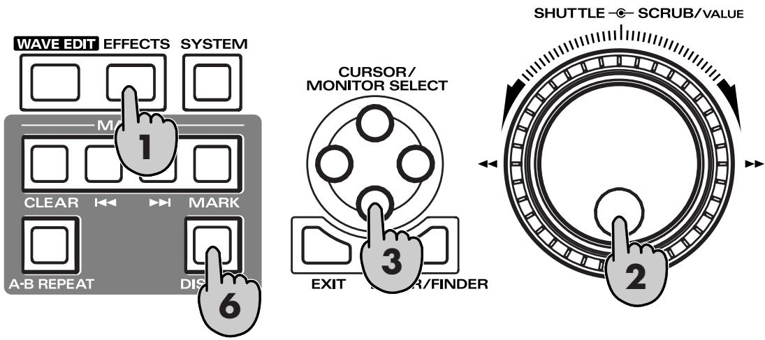
Press the R-4's [EFFECTS] button.
The effect setting screen will appear in the display.
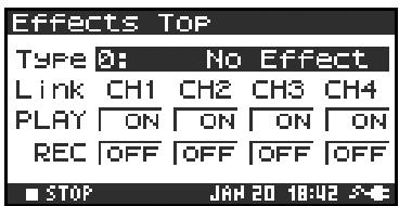
2 Use the [SCRUB/VALUE] dial to select the desired effect type.
For details on each effect type, refer to "Effects" (p. 56).
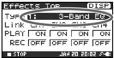
3 Press the [CURSOR] down button. The cursor will move to the "Link" setting.
| CH1 CH2 CH3 CH4 | The effect on/off setting and effect parameter settings will be independent for each channel. |
| CH1+2 CH3+4 | The effect on/off setting and effect parameter settings will be linked for channels 1 and 2, and for channels 3 and 4. Choose this setting if the project uses channels 1 and 2 and channels 3 and 4 as stereo pairs. |
| CH1+2+3+4 | The effect on/off setting and effect parameter settings will be linked for all channels. |

Use the [SCRUB/VALUE] dial to specify the channels for which effect settings will be linked.
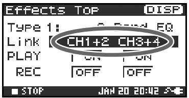

In the same way, make the desired settings for "PLAY" and "REC"
PLAY
| OFF | The effect will not be applied during playback |
| ON | The effect will be applied during playback |
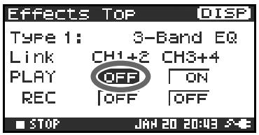
REC
| OFF | The effect will not be applied during recording |
| ON | The effect will be applied during recording |
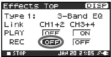

Press the [DISPLAY] button.
The effect parameter screen will appear.
- The effect parameter screen won't appear if you've selected 0: No Effect as the Type.

Use the [CURSOR] buttons and the [SCRUB/VALUE] dial to set each effect parameter.
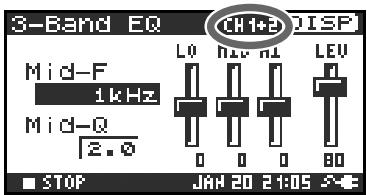

If you selected "CH1 CH2 CH3 CH4" or "CH1+2 CH3+4" as the "Link" setting, press the [DISPLAY] button.
The next channel (or pair of channels) will appear in the display.

While setting effect parameters, you can return to the previous screen by pressing the [EXIT] button. The effect settings you make are remembered until you change them. However, if you change the Type of effect, the settings you made will revert to the default values.

When you've finished making the desired effect settings, press the [EXIT] button to return to the main screen.
Each effect has various settings ("parameters") that you can adjust to alter the character of the effect. The settings you make are remembered even while the R-4's power is switched off. However, if you change the effect type, these settings will be reset to the default values.
Here you can make various settings that apply to the entire system of the R-4 as a whole, such as basic settings for recording or playback.
| No. | Menu item | Summary | Refer to |
| 1 | Recording Setup | Make various settings related to recording. | p. 65 |
| 2 | Player Setup | Make various settings related to playback. | p. 65 |
| 3 | Speaker | Turn the speaker on/off. | p. 65 |
| 4 | LCD Setup | Make settings related to the display. | p. 65 |
| 5 | System Setup | Make settings to specify how the R-4 operates. | p. 65 |
| 6 | Date & Time | Set the date and time of the R-4's internal calendar. You can specify the year, month, and date (day of the week). | p. 66 |
| 7 | Project Name | The R-4 can automatically assign a name to a project file that is created by recording. You can specify how this name will be assigned. | p. 67 |
| 8 | HDD Utility | Perform various utility commands with respect to the R-4's internal hard disk. | p. 68 |
| 9 | CF Utility | Perform various utility commands with respect to a CompactFlash card inserted in the R-4. | p. 68 |
| 10 | Factory Reset | Return the R-4 to the factory-set state. | p. 69 |
System Menu
1 Recording Setup
The values in boldface are the default values.
- You can't change the Recording Setup settings during recording or playback.
| Menu item | Value | Function | ||||||
| Input Select | Analog | This selects the type of input that is to be recorded. Choose this setting if you want to record the analog input. This is the most common setting. Connect your mic or analog audio device to the combo input jacks. With this setting, any input from the internal mics or the digital input jack will be ignored. | ||||||
| Int-Mic | Choose this setting if you want to record via the internal mics. | |||||||
| Digital | Choose this setting if you want to record via the digital input. The signal from a digital device connected to the digital input jack will be recorded. With this setting, any input from the internal mics or the line input jacks will be ignored. The sampling frequency is specified by the Rec Freq. setting, and the bit depth by the Rec Bit setting. | |||||||
| Rec Freq. | 44.1 kHz, 48.0 kHz, 96 kHz | This selects the sampling frequency for recording. Higher sampling frequencies allow higher-quality recording but will produce a larger project file, meaning that there will be less available recording time on the hard disk. The 44.1 kHz setting is sufficient when recording audio that falls within the normally audible range. This is also the most suitable frequency to use if you're going to load the recorded file into your computer and create a music CD from it. You can use the 48 kHz or 96 kHz settings when recording audio that contains a significant amount of high-frequency content, from instruments such as cymbals, or when you want to capture the brightness and transparency of a natural environment. | ||||||
| Rec Bit | 16 bit, 24 bit | This selects the sample size (bit depth) for recording. A larger sample size allows the sound to be captured in greater detail but will produce a larger project file, meaning that there will be less available recording time on the hard disk. Use the 16-bit setting for normal recording. This allows the broadest compatibility when loading the recorded file into your computer for playback. Use the 24-bit setting if you want to capture the tonal character and ambience in greater detail, such as when recording an instrumental or vocal performance. | ||||||
| Menu item | Value | Function | ||||||
| Rec Mode | MONOx1 | One-channel recording to one monaural file | This selects the structure of the project file that is created when you record. A monaural WAV file will be created for each channel. Choose these settings if you're using a separate mic for the vocal and performance or each speaker in a conversation, so that a separate file will be created for each channel. These settings will create monaural WAV files. If Input Select is Analog, up to four monaural files will be created. If Input Select is Int-Mic or Digital, up to two monaural files will be created.* You can't select MONO x3, or MONO x4, or STEREO x2 if Input Select is Int-Mic or Digital.* You can't select MONO x3 or MONO x4 if Rec Freq. is 96 kHz. | |||||
| MONOx2 | Two-channel recording to two monaural files | |||||||
| MONOx3 | Three-channel recording to three monaural files | |||||||
| MONOx4 | Four-channel recording to four monaural files | |||||||
| STEREOx1 | Two-channel recording to one stereo file | Two channels will be recorded as L and R in a stereo WAV file.If Input Select is Analog, one stereo file with channel 1 as L and channel 2 as R will be created. The inputs of channels 3 and 4 will be ignored. If Input Select is Int-Mic or Digital, one stereo WAV file will be created. | ||||||
| STEREOx2 | Four-channel recording to two stereo files | If Input Select is Analog, a stereo file with channel 1 as L and channel 2 as R will be created, and another stereo file with channel 3 as L and channel 4 as R will also be created.* You can't select STEREO x2 if Input Select is Int-Mic or Digital. | ||||||
| 4CHx1 | Four-channel recording to one four-channel file | Channels 1-4 will be recorded as a single WAV file. Be aware that not all computer software is able to handle four-channel WAV files.* You can't select 4CH x1 if Int-Mic is set to Digi-tal. | ||||||
| The “*” symbol means that this is not available if Input Select is set to Int-Mic or Digital. | ||||||||
| Pre Record-ing | OFF, 1-29 sec | You can specify the length of time that the sound will be captured “retroactive-ly,” starting from before the moment you pressed the [REC] (record) button. This setting specifies the number of seconds that will be captured retroactively.* The maximum time will depend on the sampling frequency, the sample size (bit depth), and the mode setting. | ||||||
| Rec Freq. | Rec Bit | Rec Mode | Pre Recording | |||||
| 44.1 | 16 | STEREO x1 | 29 | |||||
| 44.1 | 16 | STEREO x2 | 14 | |||||
| 48 | 16 | STEREO x1 | 27 | |||||
| 48 | 16 | STEREO x2 | 13 | |||||
| 48 | 24 | STEREO x1 | 18 | |||||
| 48 | 24 | STEREO x2 | 9 | |||||
| 96 | 24 | STEREO x1 | 9 | |||||
| 96 | 24 | STEREO x2 | 4 | |||||
| * The R-4 consumes power even during pre-recording. If you're running on bat-teries, you'll need to pay attention to the remaining battery amount. | ||||||||
| Menu item | Value | Function |
| Project Name | Date, Name1-8 | This specifies how names will be assigned to the project files that are recorded. You can specify that the name will be based on the date and time, or on the Project Name you specify. If you choose Date, a project recorded at one twenty-three (and 45 seconds) a.m. on January 1, 2005 will be given a name of “050101012345”. If you use the Date setting, the name of the project will tell you the time at which it was recorded; this is convenient when you’ve recorded a large number of projects and are looking for a specific one. If you use the Name setting, the project name will be the name you specified in “7 Project Name” (p. 63) plus an ascending serial number. If you specify a clear-ly identifiable project name, the names will follow an easily recognizable order, such as : SCENE001, SCENE002, ... etc. |
2 Player Setup
| Menu item | Value | Function |
| Play Mode | Single | This selects the playback mode. Only the selected project will play. |
| Sequential | All projects in the folder that contains the currently selected project will play sequentially. | |
| Repeat | OFF, ON | This selects whether playback will repeat. If Play Mode is Single, only that project will be played repeatedly. If Play Mode is Sequential, each project in the folder that contains the currently selected project will play sequentially, and then the projects in that same folder will play sequentially again. |
| X2 Play | OFF, ON | This enables/disables the double-speed playback function that is activated by pressing the [PLAY] button twice. An indication of PLAY x2 will appear at the bottom of the display. Press the [PLAY] button once again to return to normal playback. |
3 Speaker
| Menu item | Value | Function |
| Speaker Switch | OFF, ON | This switches the internal speaker on/off. * Even if this setting is on, no sound will be produced by the internal speakers during recording-standby or recording if the Recording Setup parameter In-put Select is set to Int-Mic; the speakers also will remain silent while head-phones are being used. |
4 LCD Setup
| Menu item | Value | Function |
| Contrast | 1-5-10 | This adjusts the contrast of the LCD. Higher settings will emphasize the white areas of the display. |
| BackLight | OFF, 1-10 | This adjusts the brightness of the LCD backlight. The OFF setting turns the backlight off. Higher settings will make the backlight brighter, and will consume more power. If you're operating the R-4 on battery power, pay attention to the remaining amount of battery capacity. |
| BackLight Timer | OFF, 2 sec, 5 sec, 10 sec, 20 sec | Specifies the time after which the display backlight will be turned off when the R-4 has not been operated for a certain length of time. If you're operating the R-4 on battery power, use this setting to conserve battery life. |
5 System Setup
| Menu item | Value | Function |
| Battery Time | Alkaline, Ni-MH | Set this to the type of batteries you're using. Choose the Alkaline setting if you're using alkaline batteries, or Ni-MH if you're using nickel metal-hydride batteries. * If you choose a setting that does not match the type of batteries that are actually installed, the remaining battery power indication will not be correct. |
| L-Connector | Disable, Enable | This setting Enables or Disables the function that lets the R-4 be controlled by a device connected to the L-connector. |
6 Date & Time
Here you can specify the date and time.
If Project Name is set to Date, the time you specify here will be used to specify the date in the project name.
This setting is also used for the date and time shown in the main screen.
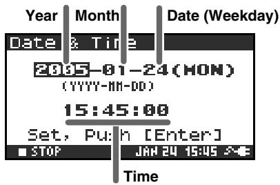
7 Project Name
You can use Name 1-8 to specify eight different names. The project name will consist of this name plus a consecutive number of 001, 002, 003 ... appended to it. For example, in the case of the default setting R4_Scene1, the project name will be R4_Scene1_001.
In order to use a name you've specified here, you'll need to set the Recording Setup parameter Project Name to Name 1-8.
Available characters
(space)!#$%&'(.)+,-.01234546789;=@
ABCDEFGHIJKLMNOPQRSTUVWXYZ[]^_abcdefghijklmnpqrstuvwxyz{}
8 HDD Utility
Here you can execute various utility commands with respect to the R-4's internal hard disk. You can't execute HDD Utility commands during recording or playback.
| Command | Explanation |
| Format | Formats the internal hard disk. All projects and folders in the internal hard disk will be erased; afterwards, the hard disk will be empty. * Be sure to back up your projects before you execute this command. |
| Check | Checks the internal hard disk, and after reorganization, frees up any hard disk space not used by R-4 projects. * There is no guarantee that this command will restore the internal hard disk to a normal operating state. Since this command directly affects the storage area of the hard disk, it is possible that projects may be affected. Be sure to back up your projects before you execute this command. |
9 CF Utility
Here you can execute various utility commands with respect to a CompactFlash card inserted on the R-4. You can't execute CF Utility commands during recording or playback.
| Command | Explanation |
| Format | Formats the CompactFlash card. All projects and folders on the CompactFlash card will be erased; afterwards, the card will be empty. * Be sure to back up your projects before you execute this command. |
| Check | Checks the CompactFlash card, and after reorganization, frees up any space on the card not used by R-4 projects. * There is no guarantee that this command will restore the CompactFlash card to a normal operating state. Since this command directly affects the storage area of the CompactFlash card, it is possible that projects may be affected. Be sure to back up your projects before you execute this command. |
10 Factory Reset
This command resets the following settings to their factory-set state. You can't execute Factory Reset during recording or playback.
Recording Setup
Player Setup
Speaker
LCD Setup
System Setup
Project Name
HDD Utility
Effects (Type, Link, Play, Rec, Parameters)
Example operations
Recording Setup settings
You can use the same procedure to make the settings listed below. As an example, we'll show how to make Recording Setup settings.
Recording Setup
Player Setup
Speaker
LCD Setup
System Setup
Press the R-4's [SYSTEM] button.
The system menu screen appears in the display.
2 Use the [CURSOR] buttons to choose 1 Recording Setup, and press the [ENTER] button.
The Recording Setup screen appears.
3 Use the [SCRUB/VALUE] dial to choose the Input Select value.
The setting is applied as soon as you select it.
You don't need to press the [ENTER] button.
4 Use the [CURSOR] buttons to choose Rec Freq.
5 Use the [SCRUB/VALUE] dial to select the Rec Freq. value.
In the same way, use the [CURSOR] buttons and the [SCRUB/ VALUE] dial to choose and set the remaining items.
7 When you've finished making settings, press the [EXIT] button. You're returned to the System Menu screen.
Press the [EXIT] button once again to return to the main screen.
If you want to make other system-related settings, use the [CURSOR] buttons to select the desired menu item.
Date & Time settings

Press the R-4's [SYSTEM] button.
The system menu screen appears in the display.

Use the [CURSOR] buttons to choose 6 Date & Time, and press the [ENTER] button.
The Date & Time screen appears.

Use the [CURSOR] buttons and the [SCRUB/VALUE] dial to specify the date and time.
When you've finished making settings, press the [EXIT] button.
You're returned to the System Menu screen.
- If you decide to cancel, press the [EXIT] button.

Press the [EXIT] button once again to return to the main screen.
If you want to make other system-related settings, use the [CURSOR] buttons to select the desired menu item.
Project Name settings
Press the R-4's [SYSTEM] button.
The system menu screen appears in the display.
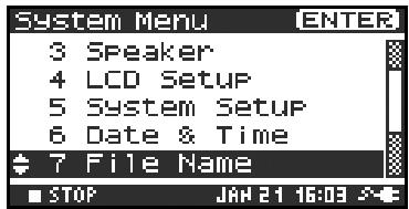
2 Use the [CURSOR] buttons to choose 7 Project Name, and press the [ENTER] button.
The Project Name screen appears.
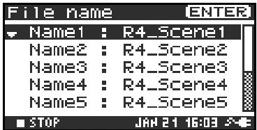
3 Use the [CURSOR] buttons to choose the Name you want to edit, and press the [ENTER] button.
A screen for editing the project name appears.
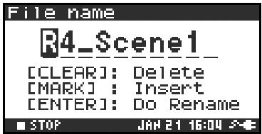
4 Use the [CURSOR] buttons, [SCRUB/VALUE] dial, [CLEAR] button, and [MARK] button to edit the name.
When you're finished, press the [ENTER] button.
You're returned to the Project Name screen.
- If you decide to cancel, press the [EXIT] button.
Available characters
(space)!#$%&'(.)+,-.01234546789;=@
ABCDEFGHIJKLMNOPQRSTUVWXYZ[]^_abcdefghijklmnpqrstuvwxyz{}
Press the [EXIT] button once again to return to the main screen.
If you want to make other system-related settings, use the [CURSOR] buttons to select the desired menu item.
Executing HDD Utility or CF Utility commands
As an example, we'll show how to execute HD Utility commands. You can also use the same procedure to execute CF Utility commands.

Press the R-4's [SYSTEM] button.
The system menu screen appears in the display.
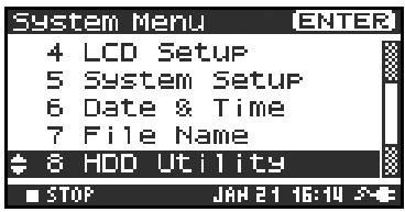

Use the [CURSOR] buttons to choose 8 HDD Utility, and press the [ENTER] button.
The HDD Utility screen appears.
If you want to execute a CF Utility command, choose 9 CF Utility.
- If you decide to cancel, press the [EXIT] button.
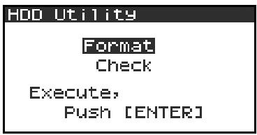
- If no CompactFlash card is inserted, the message shown at right will appear.

Use the [CURSOR] buttons to choose either "Format" or "Check," and press the [ENTER] button.


The display will ask "Are you sure?" Use the [CURSOR]
buttons to select "Yes" if you are sure you want to execute (or "No" if you decide to cancel without executing).
Then press the [ENTER] button.

The message shown at right will appear while processing is being performed.
Don't turn off the power while processing is being performed.

When processing has been completed, you will automatically return to the System Menu screen.

Press the [EXIT] button once again to return to the main screen.
If you want to make other system-related settings, use the [CURSOR] buttons to select the desired menu item.
Executing Factory Reset (Restoring the factory settings)
Press the R-4's [SYSTEM] button.
The system menu screen appears in the display.
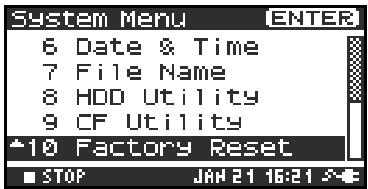
2 Use the [CURSOR] buttons to choose 10 Factory Reset, and press the [ENTER] button.
The Factory Reset screen appears.
3 Press the [ENTER] button if you want to execute Factory Reset.
- If you decide to cancel, press the [EXIT] button.

4 The display will ask "Are you sure?" Use the [CURSOR]
buttons to select "Yes" if you are sure you want to execute (or "No" if you decide to cancel without executing).
Then press the [ENTER] button.
When processing has been completed, you will automatically return to the System Menu screen.

Press the [EXIT] button once again to return to the main screen.
If you want to make other system-related settings, use the [CURSOR] buttons to select the desired menu item.
Handling memory cards
You can use CompactFlash memory cards to transfer project files from the R-4's internal hard disk to your computer, or WAV files from your computer to the R-4's hard disk.
- You can also transfer files directly via a USB connection. For details, refer to “Connecting the R-4 to your computer” (p. 72).
- You cannot record directly onto a CompactFlash card, or play back files from a CompactFlash card.
Types of CompactFlash card you can use
- You can use CompactFlash cards of up to 2 GB (gigabytes) in capacity.
- Some models or makes of CompactFlash card may not work correctly with the R-4.
-
Microdrives cannot be used.
-
Don't insert or remove a CompactFlash card while it is being accessed. Doing so may damage the data in the R-4 or in the CompactFlash card, and may damage the card itself.
- Carefully insert the CompactFlash card all the way in-until it is firmly in place.
Inserting and removing a card
Inserting
Switch off the R-4's power.
2 Open the [MEMORY CARD] slot cover, and insert the CompactFlash card with its top surface facing upward.
Insert the CompactFlash card all the way into the slot.
- If you attempt to forcibly insert the card in the wrong direction, the R-4 and the CompactFlash card may be damaged. Use caution.
3 Close the [MEMORY CARD] slot cover.
Removing
Switch off the R-4's power.
2 Make sure that data is not being written to or read from the CompactFlash card.
3 Open the [MEMORY CARD] slot cover, press the eject button, and remove the CompactFlash card.
Formatting a CompactFlash card
Before you use a CompactFlash card with the R-4, you'll need to format the card. For the formatting procedure, refer to page 68 of "Executing HDD Utility or CF Utility commands" (p. 68). CompactFlash cards formatted on a device other than the R-4 may not work correctly on the R-4. The CompactFlash card must be formatted in FAT16 format.

As an exception, you should use your Macintosh (not the R-4) to format the CompactFlash card if you will be using the card in Mac OS 9.
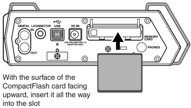
Connection to a computer
Connecting the R-4 to your computer
A project you recorded on the R-4 can be moved or copied to your computer. Likewise, files from your computer can be moved or copied to the R-4's hard disk.
Using battery power will not cause a malfunction, but we recommend that you always use the AC adaptor to prevent damage to the contents of the hard disk, which could occur if the batteries fail while the R-4 is connected to your computer.
1 Turn on the R-4's power switch.
2 Use a USB cable to connect the R-4 to your computer.
The computer will detect the R-4, and the screen shown at right will appear.
It may take several seconds for detection to occur.
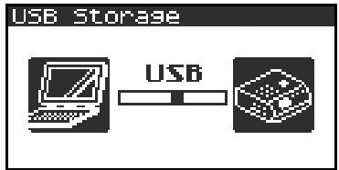
- If you see a dialog box asking you to "Windows can perform the same action each time you insert a disk or connect a device with this kind of file," click [Cancel].
The computer will detect the R-4 as follows.
| Windows | When viewed from My Computer or Explorer, the R-4 will appear as EDIROL R-4. |
| Mac OS | The R-4 will appear as EDIROL R-4 on the desktop. |
3 You can copy WAV files from the R-4 to your computer, or from your computer to the R-4.
To copy a file, drag and drop it.
Disconnecting the R-4 from your computer
Here's how to close the connection between your computer and the R-4. You must use the procedure described below to close the connection before you disconnect the USB cable.

Don't disconnect the USB cable or power down the R-4 while it's connected to your computer.
Windows
1 Close all software and windows (such as Explorer) that are referencing the R-4's hard disk.
- If any software or windows (such as Explorer) that are referencing the R-4's hard disk are open when you close the USB connection between your computer and the R-4, an error will occur and the connection will not be closed correctly.
2 In the Windows task tray, double-click the Safely Remove Hardware icon( ).
The Safely Remove Hardware dialog box will appear.
3 Select the item that indicates the R-4.
Item indicating the R-4
| Windows XP, 2000 | USB Mass Storage Device |
| Windows Me | USB Disk |
4 In the dialog box, click [Stop].
5 When the Stop a Hardware Device dialog box appears, select the item that indicates the R-4, and click [OK].
6 When your computer indicates "Safe To Remove Hardware," you can disconnect the USB cable between the R-4 and your computer. Alternatively, you can switch off power to the R-4. When you disconnect the cable, the screen shown at right will appear.
- Never switch off the R-4's power or disconnect the USB cable before you have closed the connection. Doing so may damage the internal hard disk.

Macintosh
1 Cancel the connection with the R-4 displayed on the desktop.
If you're using Mac OS X, drag the EDIROL R-4 icon into in the dock.
Normally, when you drag to the trash can located at the right edge of the dock, the indication will change from the trash can to allowing you to cancel the connection.
If you're using Mac OS 9, drag the EDIROL R-4 icon into the trash.
2 When the icon has disappeared from the desktop, you can disconnect the USB cable between the R-4 and your computer. Alternatively, you can switch off power to the R-4.
Connecting a video device that has a LANC connector
You can connect the R-4's L connector to a video device that has a LANC connector, and make the R-4 operate in synchronization with the video device.
- The R-4 does not record or synchronize to time code. Also, the recording time on the video device and the recording time on the R-4 may drift during long recordings.
LANC connection settings
Press the R-4's [SYSTEM] button. The System Menu screen appears.

2 Use the [CURSOR] buttons to choose 5 System Setup, and press the [ENTER] button.
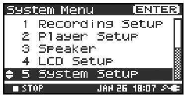
3 The System Setup screen appears. Use the [CURSOR] buttons to choose L-Connector.
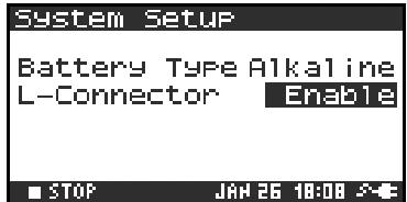
4 Use the [SCRUB/VALUE] dial to select Enable. The setting is applied when you select it. You don't need to press the [ENTER] button.
Press the [EXIT] button.
You're returned to the System Menu screen. Press the [EXIT] button once again to return to the main screen.
In this state, the R-4 will operate in synchronization with your video device. For details on settings and operation for your video device, refer to the manual of your video device.
Using the LANC connection
1 Use the special cable to connect the LANC connector of your video device to the R-4's [L-CONNECTOR].
2 Power up your video device.
3 When your video device enters recording-standby mode, the R-4 will also enter recording-standby mode.
4 When you begin (or stop) recording on your video device, the R-4 will also begin (or stop) recording.
Before you record using the R-4, you'll need to make a variety of settings so it's set up in a way that's appropriate for your recording situation and purposes.
This section gives several actual examples of applications. For details on connections refer to "Recording" (p. 27). Here we will explain the settings you'll need to make on the R-4.
Connecting an external mic for CD-quality stereo recording
This is a basic form of recording.
Panel settings
| Input level select switch | MIC |
| Phantom power switch | ON if you’re using a condenser mic that requires phantom power; otherwise OFF |
■ Recording Setup
| Input Select | Analog |
| Rec Freq. | 44.1 kHz |
| Rec Bit | 16 bit |
| Rec Mode | STEREOx1 |
| Pre Recording | OFF |
| Project Name | Date |
Recording birdsongs outdoors
Here are basic settings for recording birdsongs or similar sounds outdoors. Since you'll need to run on batteries outdoors, the settings take power conservation into account.
Panel settings
| Input level select switch | MIC |
| Phantom power switch | ON if you’re using a condenser mic that requires phantom power; otherwise OFF |
■ Recording Setup
| Input Select | Analog | By lowering the sampling frequency (Rec Freq.) and limiting the number of tracks, you can minimize the size of the file to be written. This will decrease the amount of access to the hard disk, thereby conserving power. |
| Rec Freq. | 44.1 kHz | |
| Rec Bit | 16 bit | |
| Rec Mode | STEREOx1, MONOx1 | Set to match the mics that are connected. |
| Pre Recording | 4 sec | The pre-recording setting lets you press the record button when you hear birdsong; sounds that occurred several seconds earlier will be captured retro-actively. If you're trying to capture birdsong, a setting of four seconds will be sufficient. In comparison to allowing recording to continue, this method will minimize the number of accesses to the internal hard disk. However, with any pre-recording setting other than OFF, recording will always be occurring internally. |
| Project Name | Date | Using the Date setting will make it easy to tell the date and time that the recording was made. |
LCD Setup
| BackLight Timer | 5 sec |
System Setup
| Battery Type | Set to the type of batteries you’ve installed |
Recording audio while shooting video
Here are the basic settings for using the R-4 to record audio while you're shooting video. If you're recording outdoors, the settings for "Recording birdsongs outdoors" (p. 76) can be used in this case as well, but other settings specific to video will also be necessary.
Panel settings
| Input level select switch | MIC |
| Phantom power switch | ON if you’re using a condenser mic that requires phantom power; otherwise OFF |
■ Recording Setup
| Input Select | Analog | The number of mics will depend on the video you're shooting. If you're simply recording the background sound, use two mics and record in stereo. If you're re-cording a play or an instrumental performance, you'll probably want to set up one mic for each actor or instrument. You can record up to four mics simultaneously. |
| Rec Freq. | 48 kHz | If you're going to shoot video with a video camera, and later use a video editing system to bring in the audio tracks recorded by the R-4, it's a good idea to record at 48 kHz. |
| Rec Bit | 16 bit | If you're capturing audio for use in a production in which the video is the main element, 16-bit recording provides sufficient quality. |
| Rec Mode | Set this to match the mic(s) you're using. Choose the MONO setting if each mic is assigned to a different actor or instrument. With the MONO setting, a separate WAV file will be created for each mic. In other cases you will generally use the STEREO setting. | |
| Pre Recording | OFF | Turn this OFF, since you'll be synchronizing to the video device. |
| Project Name | Name | It's convenient to assign a unique name to the project so that each recorded project will be easily identifiable; e.g., SCENE001, SCENE002, ... etc. |
System Setup
| L-Connector | Enable | Set this to Enable if you're synchronizing the R-4 with a video camera that is equipped with a LANC connector. |
Recording audio memos using just the R-4
You can use the internal mics to record on just the R-4 without needing any external equipment. However, the recording quality will be unavoidably less than when using good-quality external mics. The sound of the R-4's button operations or internal mechanism may also be present in the recording.
| Input Select | Int-Mic |
| Rec Freq. | 44.1 kHz |
| Rec Bit | 16 bit |
| Rec Mode | STEREOx1 |
| Pre Recording | OFF |
| Project Name | Date |
Simultaneously recording environmental sounds (ambience)
You can take advantage of the R-4's ability to record four channels simultaneously. You might use channels 1 and 2 to record the stage performance via line inputs, and channels 3 and 4 to record the sounds of the room or audience via mics.
Panel settings
| Input level select switch | LINE (CH1 and 2), MIC (CH3 and 4) |
| Phantom power switch | ON if you’re using a condenser mic that requires phantom power; otherwise OFF |
Recording Setup
| Input Select | Analog | Set this to Analog since you're recording from the combo in-put jacks. |
| Rec Freq. | 44.1 kHz | If you'll be using a computer to edit the waveforms after re-cording, you may wish to use a higher sampling frequency. |
| Rec Bit | 16 bit | |
| Rec Mode | STEREOx2 | Choose the STEREO x2 setting so that you can record two stereo pairs; one pair is the line feed from the stage and the other pair is the ambience mics. |
| Pre Recording | OFF, 1–29 sec | Specify the pre-recording time as desired. |
| Project Name | Date, Name | Specify a name that will help you manage the projects when you've finished recording. Date... Using the Date setting will make it easy to tell the date and time that the recording was made. Name... Assigning a unique project name, so that the projects have names such as SCENE001, SCENE002, and so forth, will make it easy to see which projects belong together. |
Simultaneously recording at different input levels
These settings are useful when you cannot afford mistakes, such as when recording an event or other nonre repeatable occasion. Even if you've set the input levels appropriately, there may be cases in which an unexpectedly loud sound causes clipping to occur; or conversely, in which the sound stays at an unexpectedly low level.
In such cases, you can use two pairs of mics and channels, each set to differing input levels, and record them simultaneously. Afterward, you can choose the best pair.
Panel settings
| Input level select switch | MIC |
| Phantom power switch | ON if you’re using a condenser mic that requires phantom power; otherwise OFF |
| Input level knobs | Set channels 1 and 2 to appropriate levels. Set channels 3 and 4 to slightly lower input levels; for example, about -12 dB lower than channels 1 and 2. |
■ Recording Setup
| Input Select | Analog |
| Rec Freq. | 44.1 kHz |
| Rec Bit | 16 bit |
| Rec Mode | STEREOx2 |
| Pre Recording | OFF |
| Project Name | Date |
This section explains the most important messages that may appear in the R-4's display
| Message | Status |
| Int-Batt Low! | Int-Batt Low! The internal battery has run low. The internal battery must be replaced. If it runs low, the internal clock will become inaccurate. Please contact one of the service locations listed on the warranty card to have the battery replaced. |
| Battery Low! | Battery Low! The batteries have run low. Install fresh batteries, or use the AC adaptor. |
| HDD Slow! | HDD Slow! Data could not be written to the hard disk fast enough. This message may be encountered after you've repeatedly written and erased project files, and have thus caused the files on the hard disk to become fragmented, slowing down the access speed. |
| Media Full! | Media Full! There is insufficient free space on the hard disk or CompactFlash card. Transfer project files to your computer to free up more space. |
| Over 2GB | Over 2GB The project is too large. This message will appear if the project newly created by appending an existing project exceeds 2 GB. The R-4 can handle files up to 2 GB in size. |
| Project exists! | Project exists! An identically named project already exists. Create the project using a different name. |
| File-Sys Error! | File-Sys Error! A problem has occurred with the file system. |
| Name too long! | Name too long! The project name is too long. This message will appear if the project name newly created when you use Trim, Combine, or copy a project is too long. You'll need to shorten the name of the source project. |
| Improper Proj. | Improper Proj. The R-4 cannot handle this project. |
| HOLD ON | HOLD ON The HOLD switch is on. This message will appear if you attempt to operate the R-4 while the HOLD switch is on. |
| Now Recording | Now Recording The R-4 is recording now. This message will appear if you attempt to operate the R-4 during recording. If you need to perform an operation, you must first stop recording. |
| Now Playing | Now Playing The R-4 is playing now. This message will appear if you attempt to operate the R-4 during playback. If you need to perform an operation, you must first stop recording. |
| LANC Offline | LANC Offline The connection with the L connector has been broken. This message will appear if signals from the L connector are interrupted, or if the cable is disconnected. |
If you experience difficulties, read this section first. It contains tips on how to resolve various problems.
Computer-related problems
Can't close the connection with the R-4
If you're using Windows, and Explorer or any other software that is referencing the R-4's hard disk is open when you attempt to close the USB connection between the R-4 and your computer, the error message "An error occurred while removing USB mass storage device - Unable to close device 'unspecified volume'."
"Please execute Stop Device again later." will appear, and you will be unable to disconnect the R-4.
Close all software or windows that are referencing the R-4's hard disk. Then execute "Safely remove hard disk" once again.
CompactFlash card inserted in the R-4 is not visible from the computer
The CompactFlash card inserted in the R-4 will not be directly visible from the computer. This means that you won't be able to manipulate projects within the CompactFlash.
Recording-related problems
Can't record
You won't be able to record correctly if the input level you specified using the input level knob is too low.
Please set the input level correctly.
Refer to: "Adjusting the input level" (p. 28)
Nor will you be able to record correctly if the input level select switch is set incorrectly. Please set the input level switch correctly.
Refer to: "Input level select switches" (p. 16)
If you're recording from a connected mic, make sure that the mic is correctly connected to the combo input jack.
Also check the setting of the input level select switch and the phantom power switch.
Refer to: “Phantom power switches [PHANTOM POWER]” (p. 10)
"Input level select switches" (p. 16)
You also won't be able to record correctly if the system setting Input Select is wrong.
Refer to: "System settings" (p. 60)
Strange sounds are heard during the recording
If you've recorded via the internal mics, you may hear metallic, mechanical clicks in the recording. These sounds are the operating noises of the R-4's internal hard disk. Due to how the R-4 is constructed, the hard disk operating sounds may affect the recording.
You can alleviate this somewhat by using the Graphic EQ effect on the REC side to lower the 2kHz and 4 kHz levels.
Recorded sound is distorted
The sound will be distorted if the input level is too high. Refer to "Adjusting the input level" (p. 28), and use the input level knob to adjust the level appropriately.
In some cases, the sound may be distorted because you've applied an effect while recording. You should adjust the input level with the effect applied. Adjust the effect parameters so that distortion does not appear.
Pan (stereo image) is not recorded correctly.
If the limiter is turned on, it will respond to the levels of each channel, meaning that when the level of a sound located toward the right (or left) side increases, the limiter for that channel will limit the volume. If you're recording in stereo, the result will be that the left and right volume difference will diminish, causing the pan (stereo image) to move toward the center.
The limiter cannot be applied to multiple channels as a group.
If you're using the Comp&DeEsser effect with channel linking (LINK) set separately for CH1, CH2, CH3, and CH4, and the compressor begins to operate on CH1 (left), this will eliminate the level difference with CH2 (right), causing the pan (stereo image) to move toward the center.
In this case, set the LINK setting to CH1+2 or CH3+4 so that whenever compression starts being applied to CH1 (left), it will be applied to CH2 (right) at the same time.
Also, the stereo image will not be recorded correctly if the input level knob settings differ significantly between L and R, so that the levels are not balanced correctly.
Even though you've set the recording levels, the sound is distorted when you turn on an effect
Since some effects work by emphasizing a portion of the sound, this may increase the volume of the overall song, thereby causing clipping (distortion). You may take either of the following two actions.
- Lower the level (LEV) values for each effect parameter
The overall volume will decrease, but the character of the effect will be maintained.
Refer to:"Effects setting" (p. 55)
- Lower the input level to decrease the volume before applying the effect
This adjustment is easy to make, but may change the resulting character of the effect.
A message of HDD Slow! appears
Writing access to the hard disk has slowed down.
As you repeatedly write and delete project files, the files on the hard disk will become fragmented, and this will slow down the processing speed.
If you are making important recordings, you should consistently delete all projects together when you're finished with them. Repeated deletion of smaller pieces of data will cause the disk to become fragmented, possibly causing recording to fail.
Playback-related problems
No sound
If the monitor level knob is turned too far down, the volume may be too low for you to hear. Gradually raise the monitor level knob.
Refer to: "Monitor level knob [MONITOR]" (p. 13)
Make sure that your headphones or speakers are connected correctly.
No sound from the internal speakers
In the system settings for Speaker, make sure that Speaker Switch is ON. No sound is output from the internal speakers if this setting is OFF.
No sound is output from the internal speakers if headphones are connected.
To prevent acoustic feedback, no sound is output from the internal speakers during recording or recording-standby.
The CompactFlash card contains a file, but the R-4 won't play it
The R-4 can't directly play files from the CompactFlash card.
In order to play a file located on the CompactFlash card, use the Finder screen to copy the file onto the R-4's hard disk, and then play it.
Refer to: "Copying a project (Copy)" (p. 44)
A skip of several seconds occurs in the project playback
If the R-4 is subjected to vibration or impact, writing to the hard disk may not occur in time, meaning that that portion of sound will not be recorded. When you listen to the recorded project, the time count during playback will not skip, but there will be a skip of several seconds in the sound of the project.
During recording, please be careful that the R-4 is not subjected to impact.
The sound skips when you play back through the internal speakers
Vibration produced by the internal speakers may cause reading from the hard disk to fail, and this may cause skips in the sound.
Try turning the monitor level knob toward the left to lower the volume of the internal speakers.
Alternatively, you can monitor through headphones.
Skipping occurs in the sound
As you repeatedly write and delete project files, the files on the hard disk will become fragmented, and this will slow down the processing speed. If you continue recording in this state, a message of "HDD Slow!" will appear, and skips may occur in the recorded project.
If you are making important recordings, you should consistently delete all projects together when you're finished with them. Repeated deletion of smaller pieces of data will cause the disk to become fragmented, possibly causing recording to fail.
Problems with the R-4's operation
Power does not turn on
Make sure that the AC adaptor is correctly connected.
If you're using batteries, make sure that each battery is securely in place and in the correct orientation. It's also possible that the batteries have run down, so you should obtain a new set of batteries.
Refer to: “Connecting the AC adaptor and turning the power on” (p. 24)
"Installing batteries and turning the power on" (p. 25)
Make sure that the HOLD switch is turned off. If it is on, the panel buttons and the scrub and shuttle dials will be inoperable.
Refer to: "Hold switch [HOLD]" (p. 10)
Finder operation is sluggish
If a folder contains a large number of files, operation will be sluggish when you open the Finder, and the screen will not scroll easily.
If there is a large number of files, operations in the Finder will take more time. Try moving projects in the folder to a different folder so that the folder contains fewer projects.
Device connected to the L connector does not work correctly
The R-4's L connector is only for reception. You cannot connect it to a controller that requires transmission functionality or power supply, and use it to operate the R-4.
Backlight turns off
The Backlight setting in LCD Setup may be set to turn off the backlight when the unit has not been operated for a while.
Refer to: "4 LCD Setup" (p. 62)
Settings you made have disappeared
If effect settings or system settings you made have reverted to their original state, it's possible that you inadvertently reset the R-4 to its factory-set condition.
Refer to: "Executing Factory Reset (Restoring the factory settings)" (p. 69)
Effect parameters you set have been initialized
Effect parameter values will be remembered as long as you don't change the effect type; they will return to the default values if you change the effect type. If you've made precise settings, it's a good idea to make a note of those settings if you want to use them again.
Refer to: "Effects setting" (p. 55)
Can't operate the panel
Make sure that the HOLD switch is turned off.
If this is on, the panel buttons and the scrub and shuttle dials will be inoperable.
Refer to: "Hold switch [HOLD]" (p. 10)
Project names and folder names in the main switch or Finder are garbled
WAVE file or folder names that contain double-byte characters (e.g., Japanese) are not displayed correctly. In some cases, it will not be possible to Rename them successfully.
Refer to: "Available characters" (p. 63)
Recorder Part
Channels
4
Signal Processing
AD/DA Conversion: 24 bits Sampling Frequency: 44.1 / 48 / 96kHz
Data Type
Format: WAV Sampling Frequency: 44.1/48/96 kHz Bit Depth: 16/24 bits
Media
Internal Hard Disk Drive (40 GB) CompactFlash (supports 32 MB-2 GB)
Recording Time
16 bit/44.1 kHz (Stereo): 58 hours
16 bit/48 kHz (Stereo): 53 hours
24 bit/48 kHz (Stereo): 35 hours
16 bit/96 kHz (Stereo): 17 hours
-
These recording times are approximate. Your actual results may vary somewhat.
-
If more than one recorded file exists, the total recordable time will be less than these.
Audio Input and Output Part
Analog Inputs
Channel 1-4: XLR type (phantom powered), 1/4 inch TRS phone type (balanced/unbalanced) Internal Microphone (Stereo)
Analog Outputs
LINE Out: 1/4 inch phone type (L, R), RCA phono type (L, R) Headphones: Stereo 1/4 inch phone type
- Digital Input/Output
Coaxial type (conforms to IEC60958)
Input Impedance
4 k ohms
- Nominal Input Level (Variable)
Line Level: -33- +4 dBu
MIC Level: -60- -23 dBu
Output Impedance
LINE Out: 950 ohms
Headphones: 10 ohms
Output Level:
LINE Out: -10 dBV
Headphones: 40mW + 40mW
- Limiter threshold level
-10 dB (relative to digital full-scale), maximum compression ratio 1:3
Residual Noise Level
LINE Out: -85 dBu
Digital Data: -90 dBFS
(fs = 96 kHz, Input: 1 k ohms terminated,
Level Switch: MIC,
Input Level Knob: Min. Input: 4 channels simultaneously)
Total Harmonic Distortion (THD + N)
0.03% (fs = 96 kHz, Input: 1 k ohms terminated, Level Switch: LINE, Input Level Knob: Min. Input: 4 channels simultaneously, Band Width: 22 kHz)
Recommended Load Impedance for Headphones
32 ohms
Frequency Response
10Hz - 40kHz (0- -3 dB)
- Phantom Power
48 + / - 2V / 8mA Available 4 Channels simultaneously (total of all channels must be 25mA or less)
- 0 dBu = 0.775 Vrms
Other Input/Output Part
- USB Interface
B Type Connector Supports USB 1.1 and 2.0 Mass Storage Device Class.
- CompactFlash Slot
Supports Type I only.
L Connector
Receiving only.
Supports Start/Stop Sync only.
Not Supports Timecode.
Effect Unit Part
Effect Type:
3-BAND SHELVING EQ, 6-BAND GRAPHIC EQ, NOISE GATE, ENHANCER, COMPRESSOR AND DE-ESSER, NO EFFECT
- Available to either recording or playing
- Not available to recording in 96 kHz sampling frequency.
Control
Power Switch
- Hold Switch
Input Gain Knobs: CH1-CH4
Monitor Level knob
- Input Level Switches: CH1/2, CH3/4 (LINE/MIC Level)
- Phantom Power Switches: CH1/2, CH3/4
- Limiter Switch
- Scrub (Value)/Shuttle Dial
- Transport Buttons:
PREV, NEXT, STOP, PLAY, PAUSE, REC - Marker Buttons: CLEAR, PREV, NEXT, MARK
- Function Buttons: WAVE EDIT, EFFECTS, SYSTEM
A-B Repeat Button - Display Button
Others
Display
128 × 64 dots Graphic LCD (backlit LCD)
Power Supply
AC Adaptor, Alkaline dry battery LR6 (AA) type x 8, or Nickel Hydrogen battery (HR15 / 51)× 8
Power Consumption
2000 mA
- Dimensions
240 (W) x 217.4 (D) x 77.1 (H) mm
9-1/2 (W) x 8-9/16 (D) x 3-1/16 (H) inches
- Weight (with batteries)
1.7 kg 3 lbs 12 oz
Accessories
Owner's Manual AC Adaptor USB cable Carrying Case
- In the interest of product improvement, the specifications and/or appearance of this unit are subject to change without prior notice.
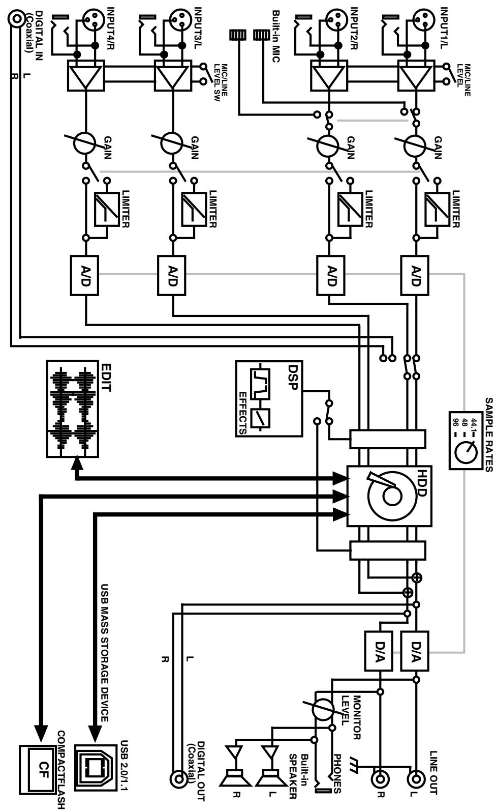
Deutsch
Beschreibung des R-4 p. 88
Français
8 Pulsante effects (EFFECTS)
Pulsante system (SYSTEM)
1 Pulsante A-B repeat (A-B REPEAT)
14 Pulsante exit (EXIT)
Pulsante play (PLAY)
24 Pulsante record (REC)
BackLight 62
BackLight Timer 62,76
batteries 25
Battery compartment 17
Battery life 26
Battery Low 79
Battery Time 63
Battery Type 76
Block diagram 86
Bottom panel 17
BWF 22
C
Carrying case 8
CF Utility 64, 68
Channel level meters 18
Channel level sliders 19
Channel names 18
Check 63-64
CLEAR 11
Clear button 11
Clip level indicators 18-19
Combine 52
Combo input jacks 16
Comp&DeEsser 57
CompactFlash 68,70
computer 72
Contrast 62
Copy 44
Cord hook 14
CURSOR/MONITOR SELECT 12
Cursor/Monitor Select buttons 12
D
Date 62
Date & Time 63, 66
DCIN 14
Delete 42
Digital 60
digital device 31
DIGITAL IN 14
Digital input connector 14
DIGITAL OUT 14
Digital output connector 14
digital recording device 35
DISPLAY 11
Display 13, 18
Display button 11
Divide 50
E
Effect button 11
EFFECTS 11
effects 55, 58
Eject button 14
Enhancer 57
ENTER/FINDER 12
Enter/Finder button 12
EXIT 12
Exit button 12
F
Factory Reset 64, 69
File-Sys Error 79
Format 63-64, 68, 71
Four-channel projects 22
Front panel 13
G
Graphic EQ 56
Grounding terminal 15
H
HDD Slow 79,81
HDD Utility 63, 68
Headphone jack 15
headphones 34
HOLD 10
HOLD ON 79
Hold switch 10
1
Improper Proj. 79
INPUT GAIN 13
Input level knobs 13,28,30,33,78
Input level select switch 16,27,32,75-78
Input Select 60,75-78
Inserting 71
Int-Batt Low 79
Internal mics 9
Internal speakers 9
Int-Mic 60
L
L connector 14
LANC 74
LANC Offline 79
LCD Setup 62
L-CONNECTOR 14
L-Connector 63,77
Level 18
Level scale 18
LIMITER 10
Limiter 27,33
Limiter switch 10
LINE OUT 16
Line output jacks 16
M
Macintosh 73
main screen 18,20
Make Folder 46
MARK 11,39
Mark button 11
MARKER 11
Marker 11
Marker indicators 18
Media Full 49, 51, 53-54, 79
MEMORY CARD 14
Memory card slot 14
Merge 54
MIC 27
MIC-L 9
MIC-R 9
mixer screen 19
Monaural projects 21
MONITOR 13
Monitor level knob 13
MONOx1 21
MONOx2 21
MONOx3 21
MONOx4 21
Move 45
N
Name 62,79
Name too long 79
NEXT 13
NEXT button 13
nickel metal-hydride 25
Ni-MH 63
Noise Gate 56
Now Playing 79
Now Recording 79
0
Output assignments 18
Output level meters 19
Over 2GB 79
P
PAUSE 13
Pause button 13
PHANTOM POWER 10
Phantom power switch 10, 27, 30, 32, 75-78
PHONES 15
pjt 22
PLAY 13
Play button 13
Play Mode 36, 62
Player Setup 36, 62
POWER 9,24
Power source 19
Power switch 9
Pre Recording 61,75-78
PREV 13
PREV button 13
Progress bar 18
Project exists 79
Project Name 18,62-63,67,75-78
R
REC 13
Rec Bit 60,75-78
Rec Freq. 60, 75-78
Rec Mode 61, 75-78
Record button 13,28,30-31,33
Recordable time 20
Recording Setup 65
Recording-standby 28
Remaining hard disk capacity 20
Remaining time 19
Removing 71
Rename 43
Repeat 36, 62
s
Sample size 18
Sampling frequency 18
Scrub dial 12
SCRUB/VALUE 12
Security Slot 15
Select 41
Sequential 62
SHUTTLE 12
Shuttle dial 12
Side panel 14, 16
Single 62
Speaker 37,62
Speaker Switch 62
Stereo 22
Stereo projects 22
STEREOx1 22
STEREOx2 22
STOP 13
Stop button 13
SYSTEM 11
System button 11
System settings 27, 30-32, 60
System Setup 63
T
Time counter 18, 20
Top panel 9
Total recording time 20
Total time 18
Trim 48
U
USB 14
USB cable 8
USB connector 14
W
wav 22
WAVE EDIT 11
Waveeditbutton 11
Windows 73
X
X2 Play 36, 62
IMPORTANT: THE WIRES IN THIS MAINS LEAD ARE COLOURED IN ACCORDANCE WITH THE FOLLOWING CODE.
BLUE: NEUTRAL
BROWN: LIVE
As the colours of the wires in the mains lead of this apparatus may not correspond with the coloured markings identifying the terminals in your plug, proceed as follows:
The wire which is coloured BLUE must be connected to the terminal which is marked with the letter N or coloured BLACK. The wire which is coloured BROWN must be connected to the terminal which is marked with the letter L or coloured RED.
Under no circumstances must either of the above wires be connected to the earth terminal of a three pin plug.
For the USA
DECLARATION OF CONFORMITY Compliance Information Statement
Model Name: R-4
Type of Equipment : 4-CHANNEL PORTABLE REORDER and WAVE EDITOR
Responsible Party : Edirol Corporation North America
Address: 425 Sequoia Drive, Suite 114, Bellingham, WA 98226
Telephone: (360) 594-4276
- Microsoft and Windows are registered trademarks of Microsoft Corporation.
- Windows® is known officially as: "Microsoft® Windows® operating system."
- Apple and Macintosh are registered trademarks of Apple Computer, Inc.
- Mac OS is a trademark of Apple Computer, Inc.
- All product names mentioned in this document are trademarks or registered trademarks of their respective owners.
- CompactFlash and ◆ are trademarks of SanDisk Corporation and licensed by CompactFlash association.
- Roland Corporation is an authorized licensee of the CompactFlash™ and CF logo ( ◆) trademarks.
- Fugue © 2005 Kyoto Software Research, Inc. All rights reserved.
-EDIROL
EUROPE
EDIROL (Europe) Ltd.
Studio 3.4 114 Power Road London W4 5PY
U.K.
TEL: +44 (0)20 8747 5949
FAX:+44 (0)20 8747 5948
http://www.edirol.com/europe
Deutschland
TEL:070033476520
France
TEL:0810000371
Italia
TEL: 02 93778329
U.S.A./CANADA
EDIROL Corporation
North America
425 Sequoia Drive, Suite 114
Bellingham, WA 98226
U.S.A
TEL: (360) 594-4273
FAX: (360) 594-4271
http://www.edirol.com/
Roland
AFRICA
EGYPT
Al Fanny Trading Office
9, EBN Hagar A1 Askalany
Street,
ARD E1 Golf, Heliopolis,
Cairo 11341, EGYPT
TEL: 20-2-417-1828
REUNION
Main Road, Claremont 7708
SOUTH AFRICA
TEL: (021) 674 4030
ASIA
CHINA
Roland Shanghai Electronics
Co,Ltd
5F. No.1500 Pingliang Road
Shanghai 200090, CHINA
TEL: (021) 5580-0800
Roland Shanghai Electronics
Co,Ltd.
(BEIJING OFFICE)
10F.No.183 Section Anhuaxili
Chaoyang District Beijing
100011 CHINA
TEL: (010) 6426-5050
Roland Shanghai Electronics
Co,Ltd.
(GUANGZHOU OFFICE)
2/F., No.30 Si You Nan Er Jie
Yi Xiang, Wu Yang Xin Cheng
Guangzhou 510600, C
TEL: (020) 8736-0428
HONG KONG
Parsons Music Ltd.
8th Floor, Railway Plaza, 39
Chatham Road South, T.S.T.
Kowloon, HONG KONG
TEL: 2333 1863
INDIA
Rivera Digitec (India) Pvt. Ltd.
409, Nirman Kendra
Mahalaxmi Flats Compound 66
Off. Dr. Edwin Moses Road, TEL: (011) 4615 5666
Mumbai-40001
TEL: (822) 2163
TEL: (022) 2493 9051
INDONESIA
PT Citra IntiRama
J1. Cideng Timur No. 15J-150
Jakarta Pusat
INDONESIA
TEL: (021) 6324170
KOREA
Cosmos Corporation
1461-9, Seocho-Dong,
Seocho Ku, Seoul, KOREA
TEL: (02) 3486-8855
MALAYSIA/
SINGAPORE
Roland Asia Pacific Sdn. Bhd.
45-1, Block C2, Jalan PJU 1/39
Dataran Prima, 47301 Petalii
Jaya, Selangor, MALAYSIA
TEL: (03) 7805-3263
PHILIPPINES
G.A. Yupangco & Co. Inc.
339 Gil J. Puyat Avenue
Makati, Metro Manila 1200,
PHILIPPINES
TEL: (02) 899 9801
TAIWAN
ROLAND TAIWAN
ENTERPRISE CO., LTD.
Room 5, 9fl. No. 112 Chung
Shan N. Road Sec.2, Taipei, Taiwan
TAIWAN,ROC TEL.(32)251-223
TEL: (02) 2561 3339
THAILAND
Theera Music Co., Ltd.
330 Verng NakornKasem, Soi
2, Bangkok 10100, THAILAND
TEL: (02) 2248821
VIETNAM
Saigon Music
Suite DP-8
40 Ba Huyen Thanh Quan
Street
Hochiminh City, VIETNAM
TEL: (08) 930-1969
AUSTRALIA/ NEW ZEALAND
AUSTRALIA/
NEW ZEALAND
Roland Corporation
Australia Pty..Ltd.
38 Campbell Avenue
Dee Why West. NSW 2099
AUSTRALIA
For Australia
Tel: (02) 9982 8266
For New Zealand
Tel: (09) 3098 715
CENTRAL/LATINAMERICA
ARGENTINA
Instrumentos Musicales S.A.
Av.Santa Fe 2055
(1123) Buenos Aires
ARGENTINA
TEL: (011) 4508-2700
BARBADOS
A&B Music Supplies LTD
12 Webster Industrial Park
Wildey, St.Michael, Barbados
TEL: (246)430-1100
BRAZIL
Roland Brasil Ltda.
Rua San Jose, 780 Sala B
Parque Industrial San Jose
Cotia - Sao Paulo - SP, BRAZIL
TEL: (011) 4615 5666
CHILE
Comercial Fancy II S.A.
Rut.: 96,919,420-1
Nataniel Cox #739, 4th Floor
Santiago - Centro, CHILE
TEL: (02) 688-9540
COLOMBIA
Centro Musical Ltda.
Cra 43 B No 25 A 41 Bododega 9
Medellin, Colombia
TEL: (574)3812529
CURACAO
Zeelandia Music Center Inc.
Orionweg 30
Curacao, Netherland Antilles
TEL:(305)5926866
DOMINICAN REPUBLIC
Instrumentos Fernando Giraldez
155, New National Road
Patras 26442, GREECE.
TEL:2610435400
HUNGARY
Roland East Europe Ltd.
Warehouse Area DEPO' Pf.83
H-2046 Torokbalint,
HUNGARY
TEL: (23) 511011
IRELAND
Roland Ireland
G2 Calmount Park, Calmount
Avenue, Dublin 12
Republic of IRELAND
TEL: (01) 4294444
ITALY
Roland Italy S. p. A
Danvik Center 28, 2 tr.
S-131 30 Nacka SWEDEN
TEL: (0)8702 00 20
SWITZERLAND
Roland (Switzerland) AG
Roland (U.K.) Ltd.
Atlantic Close, Swansea
Atlantic Close, Swansea Enterprise Park, SWANSEA
SA7 9FL
UNITED KINGDOM
TEL: (01792) 702701
MIDDLE EAST
BAUPAIN
Moon Stores
No.16, Bab Al Bahrain Avenue.
P.O.Box 247, Manama 304.
State of BAHRAIN
TEL: 17 211 005
CYPRUS
Radex Sound Equipment Ltd.
17, Diagorou Street, Nicosia,
CYPRUS
TEL: (022) 66-9426
IRAN
MOCO INC.
No.41 Nike St., Dr.Shariyati Ave.,
Roberoye Cerahe Mirdamad
Tehran, IRAN
TEL: (021) 285-4169
ISRAEL
Halilit P. Greenspoon & Sons
Ltd.
8 Retzif Ha'aliya Hashnya St.
Tel-Aviv-Yafo ISRAEL
TEL: (03) 6823666
JORDAN
AMMAN Trading Agency
245 Prince Mohammad St.,
Amman 1118, JORDAN
TEL: (06) 464-1200
KUWAIT
EASA HUSAIN AL-YOUSIFI
& SONS CO.
Abdullah Salem Street,
Safat, KUWAIT
TEL: 243-6399
LEBAN
Chahine
Gerge Zeidan St., Chahine
Bldg., Achrafieh, P.O.Box: 16-
5857
Beirut,LEBANON
TEL: (01) 20-
OMAN
TALENTZ CENTRE L.L.C.
P.O. BOX 37, MUSCAT,
POSTAL CODE 113
TEL:931-3705
QATAR
Badie Studio & Stores
P.O.Box 62
Doha, QATAR
TEL: 423554
SAUDI ARABIA
aDawliah Universal
Electronics APL
Corniche Road, Aldossary
Bldg., 1st Floor, Alkhobar,
SAUDI ARABIA
P.O.Box 2154,Alkhobar 31952
SAUDIARA
TEL: (03) 898 2081
SYRIA
Technical Light & Sound
Center
Rawda, Abdul Qader Jazair
Bldg. No. 21, P.O.BOX 13520
Damascus, SYRIA
TEL: (011) 223-5384
TURKEY
Zak Electronics & Musical
Instruments Co. L.L.C
Zabeel Road, Al Sherooq Bldg.
No.14, Grand Floor, Dubai,
U.A.E.
TEL: (04) 3360715
January 15, 2005 (EDIROL-1)