
UA-700 - Audio Interface EDIROL - Free user manual and instructions
Find the device manual for free UA-700 EDIROL in PDF.
| Product type | USB 2.0 audio interface with microphone preamps, guitar input, COSM modeling, and built-in effects |
| Dimensions (approx.) | 210 x 150 x 45 mm |
| Weight (approx.) | 0.8 kg |
| Power supply | AC adapter (LIVOO) included |
| Analog inputs | 2 microphone inputs (XLR/TRS combo) with 48V phantom power, 1 high-impedance guitar input (6.35 mm jack), 2 line inputs (6.35 mm jack) |
| Analog outputs | 2 master outputs (RCA), 2 general outputs (6.35 mm jack), 1 headphone output (6.35 mm jack) |
| Digital inputs/outputs | Optical and coaxial input, optical and coaxial output |
| MIDI | MIDI input and output (DIN 5-pin) |
| Connectivity | USB B for computer connection |
| Sampling frequencies | 32, 44.1, 48, 96 kHz (depending on mode) |
| Resolution | 24-bit |
| Main functions | Microphone modeling (COSM), guitar amp modeling (COSM), compressor/de-esser, noise suppressor/equalizer, chorus/reverb, guitar effects (flanger, tremolo, phaser, delay, compressor), center cancel, phono equalizer |
| Patch storage | 6 user patches |
| Supported drivers | WDM, MME (Windows), OMS, FreeMIDI, ASIO (Mac) |
| Maintenance and cleaning | Unplug the device before cleaning. Use a dry, soft cloth. Avoid solvents. |
| Safety | Do not expose to moisture. Use the supplied AC adapter. Follow the power-on sequence. |
| Spare parts and repairability | Contact authorized after-sales service. Do not open the device. |
| General information | Versatile audio interface for musicians and producers. Manual available in multiple languages at notice-facile.com. |
Frequently Asked Questions - UA-700 EDIROL
User questions about UA-700 EDIROL
0 question about this device. Answer the ones you know or ask your own.
Ask a new question about this device
Download the instructions for your Audio Interface in PDF format for free! Find your manual UA-700 - EDIROL and take your electronic device back in hand. On this page are published all the documents necessary for the use of your device. UA-700 by EDIROL.
USER MANUAL UA-700 EDIROL
Thank you for purchasing the UA-700 USB Audio Interface.
Before using this unit, carefully read the sections entitled: "USING THE UNIT SAFELY" and "IMPORTANT NOTES" (Owner's manual pp. 2--5). These sections provide important information concerning the proper operation of the unit. Additionally, in order to feel assured that you have gained a good grasp of every feature provided by your new unit, Owner's manual should be read in its entirety. The manual should be saved and kept on hand as a convenient reference.
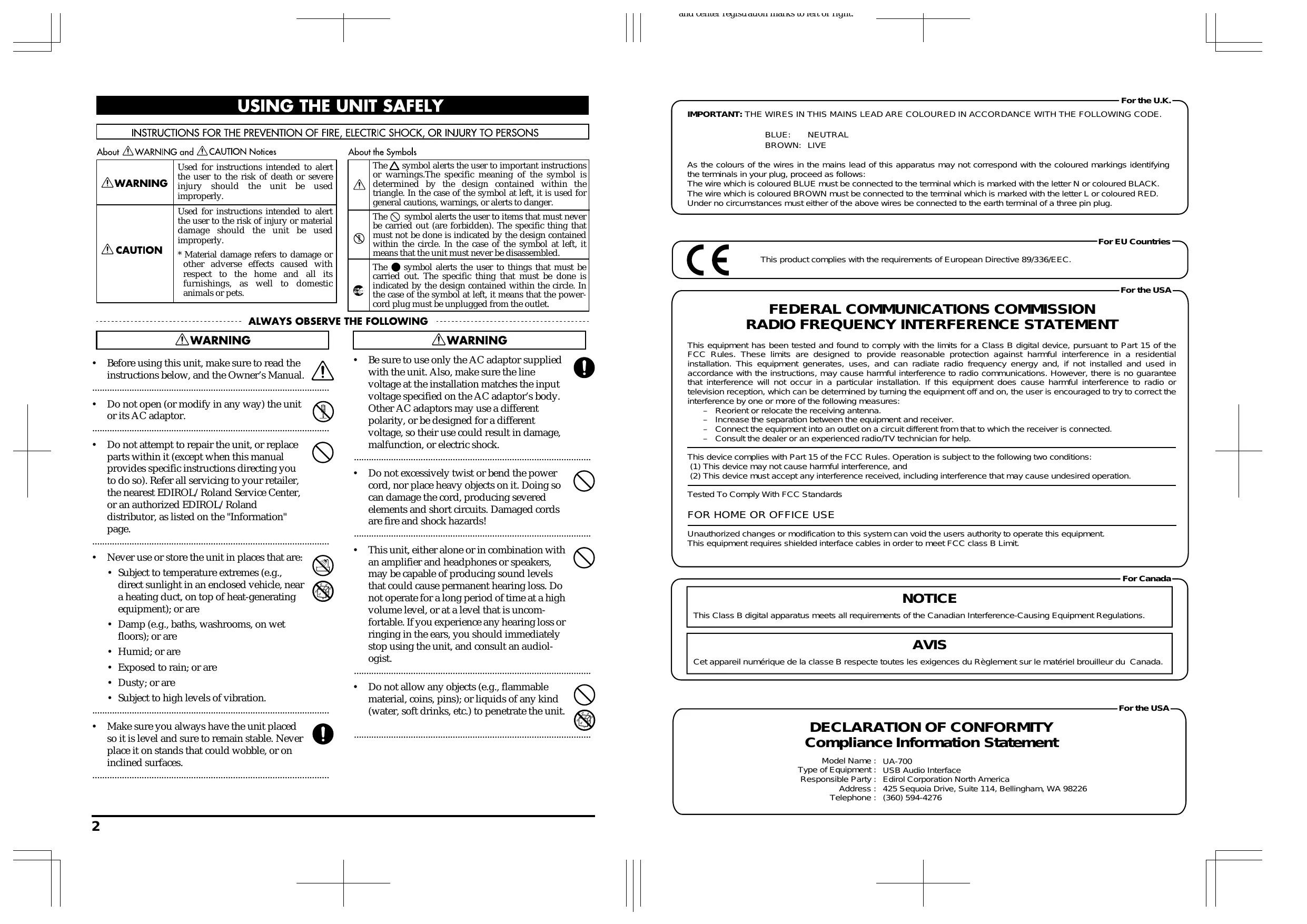
USING THE UNIT SAFELY
INSTRUCTIONS FOR THE PREVENTION OF FIRE, ELECTRIC SHOCK, OR INJURY TO PERSONS
About WARNING and CAUTION Notices
| ▲WARNING | Used for instructions intended to alert the user to the risk of death or severe injury should the unit be used improperly. |
| ▲CAUTION | Used for instructions intended to alert the user to the risk of injury or material damage should the unit be used improperly. * Material damage refers to damage or other adverse effects caused with respect to the home and all its furnishings, as well to domestic animals or pets. |
About the Symbols
| A | The △ symbol alerts the user to important instructions or warnings. The specific meaning of the symbol is determined by the design contained within the triangle. In the case of the symbol at left, it is used for general cautions, warnings, or alerts to danger. |
| B | The ⊙ symbol alerts the user to items that must never be carried out (are forbidden). The specific thing that must not be done is indicated by the design contained within the circle. In the case of the symbol at left, it means that the unit must never be disassembled. |
| C | The ● symbol alerts the user to things that must be carried out. The specific thing that must be done is indicated by the design contained within the circle. In the case of the symbol at left, it means that the power-cord plug must be unplugged from the outlet. |
ALWAYS OBSERVE THE FOLLOWING
WARNING
Before using this unit, make sure to read the instructions below, and the Owner's Manual.

- Do not open (or modify in any way) the unit or its AC adaptor.

- Do not attempt to repair the unit, or replace parts within it (except when this manual provides specific instructions directing you to do so). Refer all servicing to your retailer, the nearest EDIROL/Roland Service Center, or an authorized EDIROL/Roland distributor, as listed on the "Information" page.

- Never use or store the unit in places that are:

- Subject to temperature extremes (e.g., direct sunlight in an enclosed vehicle, near a heating duct, on top of heat-generating equipment); or are

- Damp (e.g., baths, washrooms, on wet floors); or are
- Humid; or are
- Exposed to rain; or are
- Dusty; or are
-
Subject to high levels of vibration.
-
Make sure you always have the unit placed so it is level and sure to remain stable. Never place it on stands that could wobble, or on inclined surfaces.

WARNING
- Be sure to use only the AC adaptor supplied with the unit. Also, make sure the line voltage at the installation matches the input voltage specified on the AC adaptor's body. Other AC adaptors may use a different polarity, or be designed for a different voltage, so their use could result in damage, malfunction, or electric shock.

- Do not excessively twist or bend the power cord, nor place heavy objects on it. Doing so can damage the cord, producing severed elements and short circuits. Damaged cords are fire and shock hazards!

- This unit, either alone or in combination with an amplifier and headphones or speakers, may be capable of producing sound levels that could cause permanent hearing loss. Do not operate for a long period of time at a high volume level, or at a level that is uncomfortable. If you experience any hearing loss or ringing in the ears, you should immediately stop using the unit, and consult an audiologist.

- Do not allow any objects (e.g., flammable material, coins, pins); or liquids of any kind (water, soft drinks, etc.) to penetrate the unit.


WARNING
-
Immediately turn the power off, remove the AC adaptor from the outlet, and request servicing by your retailer, the nearest Roland Service Center, or an authorized Roland distributor, as listed on the "Information" page when:
-
The AC adaptor or the power-supply cord has been damaged; or
- Objects have fallen into, or liquid has been spilled onto the unit; or
- The unit has been exposed to rain (or otherwise has become wet); or
-
The unit does not appear to operate normally or exhibits a marked change in performance.
-
In households with small children, an adult should provide supervision until the child is capable of following all the rules essential for the safe operation of the unit.
- Protect the unit from strong impact. (Do not drop it!)
- Do not force the unit's power-supply cord to share an outlet with an unreasonable number of other devices. Be especially careful when using extension cords—the total power used by all devices you have connected to the extension cord's outlet must never exceed the power rating (watts/amperes) for the extension cord. Excessive loads can cause the insulation on the cord to heat up and eventually melt through.
- Before using the unit in a foreign country, consult with your retailer, the nearest Roland Service Center, or an authorized Roland distributor, as listed on the "Information" page.
DO NOT play a CD-ROM disc on a conventional audio CD player. The resulting sound may be of a level that could cause permanent hearing loss. Damage to speakers or other system components may result.


CAUTION
- The unit and the AC adaptor should be located so their location or position does not interfere with their proper ventilation.

- Always grasp only the output plug or the body of the AC adaptor when plugging into, or unplugging from, this unit or an outlet.

- Whenever the unit is to remain unused for an extended period of time, disconnect the AC adaptor.

- Try to prevent cords and cables from becoming entangled. Also, all cords and cables should be placed so they are out of the reach of children.

- Never climb on top of, nor place heavy objects on the unit.

- Never handle the AC adaptor body, or its output plugs, with wet hands when plugging into, or unplugging from, an outlet or this unit.

- Before moving the unit, disconnect the AC adaptor and all cords coming from external devices.

- Before cleaning the unit, turn off the power and unplug the AC adaptor from the outlet.

- Whenever you suspect the possibility of lightning in your area, disconnect the AC adaptor from the outlet.

- Should you remove the optical connector caps, make sure to put them in a safe place out of children's reach, so there is no chance of them being swallowed accidentally.

IMPORTANT NOTES
In addition to the items listed under "USING THE UNIT SAFELY" on page 2 and 3, please read and observe the following:
Power Supply
- Do not use this unit on the same power circuit with any device that will generate line noise (such as an electric motor or variable lighting system).
- The AC adaptor will begin to generate heat after long hours of consecutive use. This is normal, and is not a cause for concern.
- Before connecting this unit to other devices, turn off the power to all units. This will help prevent malfunctions and/or damage to speakers or other devices.
Placement
- Using the unit near power amplifiers (or other equipment containing large power transformers) may induce hum. To alleviate the problem, change the orientation of this unit; or move it farther away from the source of interference.
- This device may interfere with radio and television reception. Do not use this device in the vicinity of such receivers.
- Noise may be produced if wireless communications devices, such as cell phones, are operated in the vicinity of this unit. Such noise could occur when receiving or initiating a call, or while conversing. Should you experience such problems, you should relocate such wireless devices so they are at a greater distance from this unit, or switch them off.
- To avoid possible breakdown, do not use the unit in a wet area, such as an area exposed to rain or other moisture.
Maintenance
- For everyday cleaning wipe the unit with a soft, dry cloth or one that has been slightly dampened with water. To remove stubborn dirt, use a cloth impregnated with a mild, non-abrasive detergent. Afterwards, be sure to wipe the unit thoroughly with a soft, dry cloth.
- Never use benzine, thinners, alcohol or solvents of any kind, to avoid the possibility of discoloration and/or deformation.
Additional Precautions
- Please be aware that the contents of memory can be irretrievably lost as a result of a malfunction, or the improper operation of the unit. To protect yourself against the risk of loosing important data, we recommend that you periodically save a backup copy of important data you have stored in the unit's memory in another MIDI device (e.g., a sequencer).
- Unfortunately, it may be impossible to restore the contents of data that was stored in another MIDI device (e.g., a sequencer) once it has been lost. Roland Corporation assumes no liability concerning such loss of data.
- Use a reasonable amount of care when using the unit's buttons, sliders, or other controls; and when using its jacks and connectors. Rough handling can lead to malfunctions.
- When connecting / disconnecting all cables, grasp the connector itself—never pull on the cable. This way you will avoid causing shorts, or damage to the cable's internal elements.
- To avoid disturbing your neighbors, try to keep the unit's volume at reasonable levels. You may prefer to use headphones, so you do not need to be concerned about those around you (especially when it is late at night).
-
When you need to transport the unit, package it in the box (including padding) that it came in, if possible. Otherwise, you will need to use equivalent packaging materials.
-
Use a cable from Roland to make the connection. If using some other make of connection cable, please note the following precautions.
- Some connection cables contain resistors. Do not use cables that incorporate resistors for connecting to this unit. The use of such cables can cause the sound level to be extremely low, or impossible to hear. For information on cable specifications, contact the manufacturer of the cable.
Handling CD-ROMs
- Avoid touching or scratching the shiny underside (encoded surface) of the disc. Damaged or dirty CD-ROM discs may not be read properly. Keep your discs clean using a commercially available CD cleaner.
Copyright
- Unauthorized recording, distribution, sale, lending, public performance, broadcasting, or the like, in whole or in part, of a work (musical composition, video, broadcast, public performance, or the like) whose copyright is held by a third party is prohibited by law.
- When exchanging audio signals through a digital connection with an external instrument, this unit can perform recording without being subject to the restrictions of the Serial Copy Management System (SCMS). This is because the unit is intended solely for musical production, and is designed not to be subject to restrictions as long as it is used to record works (such as your own compositions) that do not infringe on the copyrights of others. (SCMS is a feature that prohibits second-generation and later copying through a digital connection. It is built into MD recorders and other consumer digital-audio equipment as a copyright-protection feature.)
-
Do not use this unit for purposes that could infringe on a copyright held by a third party. We assume no responsibility whatsoever with regard to any infringements of third-party copyrights arising through your use of this unit.
-
Microsoft and Windows are registered trademarks of Microsoft Corporation.
- Screen shots in this documents are reprinted with permission from Microsoft Corporation.
- Windows® XP is known officially as: "Microsoft® Windows® XP operating system".
- Windows® 2000 is known officially as: "Microsoft® Windows® 2000 operating system".
- Windows® Me is known officially as: "Microsoft® Windows® Millennium Edition operating system".
- Windows® 98 is known officially as: "Microsoft® Windows® 98 operating system".
- Apple and Macintosh are registered trademark of Apple Computer, Inc.
- MacOS is a trademark of Apple Computer, Inc.
- OMS is a registered trademark of Opcode Systems, Inc.
- FreeMIDI is a trademark of Mark of the Unicorn, Inc.
- ASIO is trademark of Steinberg Media Technologies AG.
- All product names mentioned in this document are trademarks or registered trademarks of their respective owners.
Contents
IMPORTANT NOTES 4
Contents 6
Features of the UA-700 10
Built-in COSM effects 10
24-bit/96 kHz data for pristine audio quality 10
Wide variety of input/output jacks 10
Direct Monitor function 10
WDM/ASIO 2.0 drivers included 10
Contents of the package 12
Setup 13
Getting Connected and Installing Drivers (Windows) 14
What is a driver? 14
Advanced mode and Standard driver mode 14
Installing the special driver 15
Installing the OS-standard driver 28
Settings and checking 33
Check whether there is sound. 38
Getting Connected and Installing Drivers (Macintosh) 39
What is a driver? 39
Advanced mode and Standard driver mode 39
Installing the special driver 40
Installing the ASIO driver. 47
Installing the OS-standard driver 48
Einstellungen und Überprüfung 60
Überprüfung, ob Sound zu horen ist 61
Installation des speziellen Treibers 63
Installation des ASIO-Treibers 70
Configuration et contrôle 81
Vérifiez la présence de son 82
Installation du pilote spécial 84
Installation du pilote ASIO. 92
Configurazione e verifica 102
Verificare se l'audio viene riprodotto. 103
Installatione del driver speciale 105
Installazione del driver ASIO 113
Operation 114
Names of things and what they do. 115
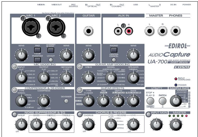
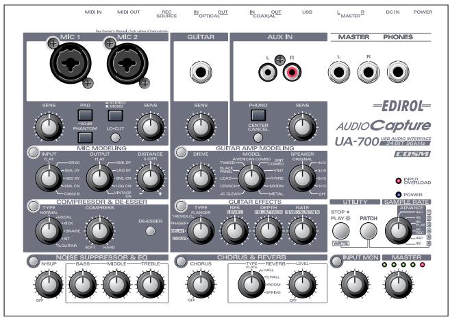
Panel. 115
Rear panel. 127
Application guide. 129
Basic use 129
Recording a guitar or bass 130
Recording from mics 131
Recording a keyboard 132
Analog recording from an audio device 133
Input audio from a CD/MD/DAT to your computer. 134
Digitally recording the UA-700's output to an MD 135
Adjusting the audio latency 135
Using ASIO Direct Monitor 136
Advanced applications. 138
Customizing the effects 138
Adjusting the volume of the effects. 141
Switching patches from an external device 142
Sequencer control switch settings. 143
Send/Return mode 144
Restoring the factory settings 145
Limitations at 96 kHz 145
Block diagram. 145
Problems related to the USB driver 241
Problems when using the UA-700 243
Deleting the special driver 251
MIDI implementation 254
Specifications. 261
Index 263
Features of the UA-700
Thank you, and congratulations on your choice of the UA-700. The UA-700 is an audio interface that can be connected to your computer via a USB cable, allowing you to digitally record and play back high-quality audio data.
Built-in COSM effects
The UA-700 features the same COSM engine that has won acclaim with the BOSS GP-20 and GT-6. From the heavy distortion of a tube amp, to a lightly distorted crunch sound, or the clean sound typical of a JC-120, these effects deliver the powerful tones of a guitar amp, faithfully simulating even the subtle impact of picking and volume.
24-bit/96 kHz data for pristine audio quality
You can enjoy high-quality digital recording/playback on your computer using 24-bit/96 kHz* data.
- Your application must support 24-bit/96 kHz data.
- Simultaneous recording and playback at 96 kHz is not possible.
Wide variety of input/output jacks
Two combo-type jacks, which provide both XLR balanced (with phantom power) and TRS balanced inputs, are provided. One input provides a high-impedance (Hi-Z) connection for directly connecting your guitar or bass. The UA-700 also provides RCA phono-type inputs and outputs, phone outputs, and digital input/output jacks (coaxial and optical), making it possible for you to readily connect almost any kind of device.
Direct Monitor function
The Direct Monitor function lets you monitor the input signal directly from headphones or the analog outputs without passing the audio through your computer application. You can also switch the monitor function on/off from an ASIO^ 2.0 compatible application.
WDM/ASIO 2.0 drivers included
You can enjoy high performance with WDM compatible applications such as SONARTM, and ASIO compatible applications such as CubaseTM and LogicTM. Of course you can also use applications that support MME (Windows®) or Sound Manager (Mac OS®).
- Roland provides no guarantee or support regarding the operation of sequencer software or audio editing software made by other companies. Please contact the manufacturer of the software you are using.
What is USB?
USB stands for Universal Serial Bus. It is a new interface used to connect various peripheral devices to a computer.
USB allows more than one peripheral device to be connected via a single USB cable, and also allows data to be transmitted more rapidly than conventional serial ports.
Peripherals can also be connected or disconnected with the power turned on, and the computer will automatically recognize the peripheral that has been plugged in. (Some peripherals may require settings or other operations to be performed.)
About SCMS
SCMS (Serial Copy Management System) is a function that protects the rights of the copyright owner by prohibiting second-generation or later copying via a digital connection to a consumer digital audio device such as a DAT recorder or MD recorder. When a recording is made via a digital connection on a digital recorder that has this function, SCMS data will be recorded along with the digital audio signal. A digital audio signal containing this SCMS data cannot be recorded again via a digital connection.
Contents of the package
UA-700
- AC adaptor
This is the only AC adaptor you should use with the UA-700. Do not use any AC adaptor other than the supplied one, since doing so may cause malfunction.
The ferrite core attached to the cable of the AC adaptor is for the purpose of preventing electromagnetic interference. Do not remove it. (However, the ACI-120C AC adaptor does not come with a ferrite core, since it is unnecessary.)
- If you require a replacement due to loss or damage, please contact a "EDIROL/Roland Service Center" listed in the "Information" section at the end of this manual. If you purchase a new AC adaptor, please specify the special AC adaptor with ferrite core designed for the UA-700.
USB cable
Use this to connect the USB connector of your computer with the USB connector of the UA-700. For details on connections and driver installation, refer to Getting Connected and Installing Drivers (Windows p. 14 or Macintosh p. 39).
- Please use only the included USB cable. If you require a replacement due to loss or damage, please contact a "EDIROL/Roland Service Center" listed in the "Information" section at the end of this manual.
CD-ROM
This contains the driver required in order to use the UA-700.
Owner's Manual
This is the manual you are reading. Please keep it on hand for reference.
Setup
This section explains how to install the drivers needed for connecting the UA-700 to a computer, and make the necessary settings.
Getting Connected and Installing Drivers (Windows) (p. 14)
Getting Connected and Installing Drivers (Macintosh) (p. 39)
If you are using a Macintosh computer, please proceed to Getting Connected and Installing Drivers (Macintosh) (p. 39).
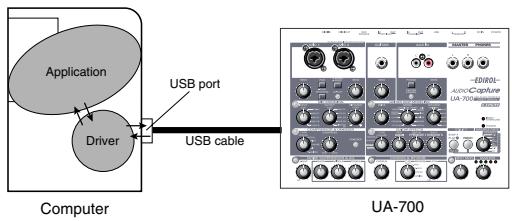
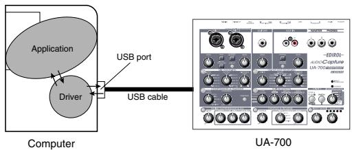
What is a driver?
A "driver" is software that transfers data between the UA-700 and application software running on your computer, when your computer and the UA-700 are connected by a USB cable. The driver sends data from your application to the UA-700, and from the UA-700 to your application.
Advanced mode and Standard driver mode
The UA-700 has two operating modes, Advanced mode and Standard driver mode, and a different driver is used by each mode.
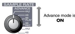
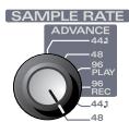
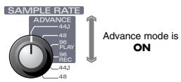
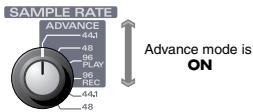
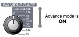
■ Advanced mode
The UA-700 will operate in this mode when the ADVANCE mode is turned ON. (→Refer to ADVANCE (mode select) switch (p. 125)) The special driver included on the CD-ROM will be used, allowing audio to be recorded/played/edited with high quality and stable timing.
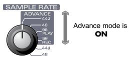
In Advanced mode, audio signals can be transferred between the UA-700 and the computer at a resolution of 24 bits and sampling frequencies of 44.1 / 48 / 96kHz . Select this mode if you are using an application that allows high-quality audio recording/playback/editing, such as an application that supports 24 bit audio (e.g., the Cakewalk series or Cool Edit) or an ASIO-compatible application (e.g., Cubase VST or Logic Audio). ( Installing the special driver (p. 15))
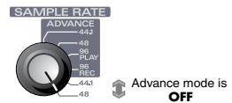
Standard driver mode
The UA-700 will operate in this mode when the ADVANCE mode is turned OFF. ( Refer to ADVANCE (mode select) switch (p. 125))
The standard USB audio driver included with Windows will be used. In standard driver mode, audio signals are transferred between the
UA-700 and the computer at a resolution of 16 bits and sampling
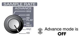
frequencies of 44.1 kHz. Select this mode if you are using an application that uses Window's own functionality, such as an application that uses the computer's CD-ROM drive to play back CD-audio, or an application that uses the software synthesizer included with Windows.
The standard driver that is included with Windows does not support ASIO.
( Installing the OS-standard driver (p. 28))
- If you want to use MIDI, use Advanced mode.
- The standard driver included with Windows does not support ASIO.
Switching between Advanced mode and Standard driver mode
If you first install both the special driver and the standard driver, you will be able to switch between Advance and Standard driver modes by operating the UA-700's ADVANCE (mode select) switch.
- In order for the setting of the ADVANCE (mode select) switch to take effect, you must exit all sequencer software and other applications that use the UA-700, switch off the UA-700, then turn it back on again.
Installing the special driver
The installation procedure will differ depending on your system.
Please proceed to one of the following sections, depending on the system you use.
- Windows XP/2000 users .....(p. 15)
- Windows Me/98 users............(p. 26)
Windows XP/2000 users
The CD-ROM contains two types of driver for Windows XP/2000 (WDM driver and MME driver). Normally, you should use the WDM driver.
WDM driver
You should use this driver if you have specified WDM driver mode for SONAR or a similar application. This will provide the highest-quality audio performance.
- If you are using Windows 2000, it is not possible to use 24-bit audio with applications that do not support a WDM driver mode, such as Cool Edit or Media Player.
MME driver
This driver allows you to use 24-bit audio even from applications that do not have a WDM driver mode, such as Cool Edit. It is not possible to use the MME driver from WDM driver mode of an application such as SONAR.
It is not possible to install both the WDM driver and the MME driver. You must select one beforehand, and install only that driver. If after installing one of these drivers you decide to change drivers, you must first delete the already-installed driver and then install the new driver.
( Deleting the special driver (p. 251))
- The WDM driver and the MME driver can be installed using the same procedure.
Windows XP users

With the UA-700 disconnected, start up Windows.
Disconnect all USB cables except for a USB keyboard and USB mouse (if used).

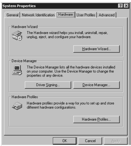
Open the System Properties dialog box.
- Click the Windows start menu, and from the menu, select Control Panel.
- In "Pick a category", click "Performance and Maintenance".
- In "or pick a Control Panel icon", click the System icon.

Click the Hardware tab, and then click [Driver Signing].
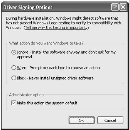
Open the Driver Signing Options dialog box.
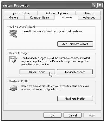

Make sure that "What action do you want Windows to take?" is set to "Ignore".
If it is set to "Ignore", simply click [OK].
If it is not set to "Ignore", make a note of the current setting
("Warn" or "Block"). Then change the setting to "Ignore" and click [OK].
After installing the driver, restore the original setting.
( If you changed "What action do you want Windows to take?" (p. 21))

If you are using
Windows XP
Professional, you must log on using a user name with an administrative account type (e.g., Administrator). For details on user accounts, please consult the system administrator of your computer.

Depending on how your system is set up, the System icon may be displayed directly in the Control Panel (the Classic view). In this case, double-click the System icon.

If you changed "What action do you want Windows to take?" in step 4, you must restore the previous setting after you have installed the driver. ( If you changed "What action do you want Windows to take?" (p.21))

Click [OK] to close the System Properties dialog box.

Exit all currently running software (applications).
Also close any open windows. If you are using virus checking or similar software, be sure to exit it as well.

Prepare the CD-ROM.
Insert the CD-ROM into the CD-ROM drive of your computer.

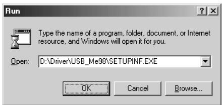
Click the Windows start button. From the menu that appears, select "Run...".
Open the "Run..." dialog box.

In the dialog box that appears, input the following into the "Open" field, and click [OK].
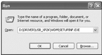
D:\Driver\USB XP2K\WDM\SETUPINF.EXE
The drive name "D:" may be different for your system. Specify the drive name of your CD-ROM drive.

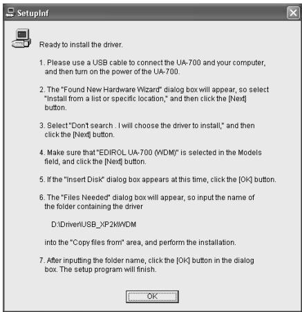
The SetupInf dialog box will appear.
You are now ready to install the driver.
MEMO
If you are using the MME driver, input MME instead of WDM.
MEMO
In this manual, the location of folders and files is given in terms of the file path, using \ as the delimiter.
For example, USB_XP2K\SETUPINF.
EXE indicates the SETUP.EXE file
found in the USB_XP2K folder.

Use the USB cable to connect the UA-700 to your computer.
- With the power switch turned OFF, connect the AC adaptor to the UA-700.
- Connect the AC adaptor to an electrical outlet.
- Use the USB cable to connect the UA-700 to your computer.

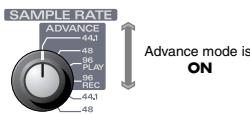
Set the UA-700's ADVANCE (mode select) switch to the ON position.
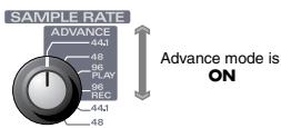

Set the UA-700's power switch to the ON position.
Near the task bar, your computer will indicate "Found New Hardware". Please wait.

The Found New Hardware Wizard will appear.
Make sure that the screen indicates "EDIROL UA-700 (WDM)", select "Install from a list or specific location (Advanced)", and click [Next].
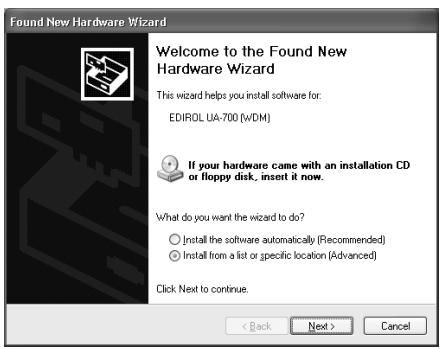

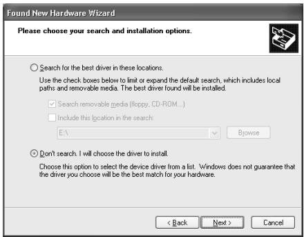
The screen will indicate "Please choose your search and installation options".
Select "Don't search. I will choose the driver to install", and click [Next].

Once the connections have been completed, turn on power to your various devices in the order specified. By turning on devices in the wrong order, you risk causing malfunction and/or damage to speakers and other devices.

This unit is equipped with a protection circuit. A brief interval (a few seconds) after power up is required before the unit will operate normally.

In the case of the MME driver, make sure that "EDIROL UA-700 (MME)" is displayed.
17
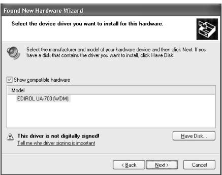
Make sure that the "Model" field indicates "EDIROL UA-700
(WDM)”, and click [Next]. Driver installation will begin.
MEMO
In the case of the MME driver, make sure that "EDIROL UA-700 (MME)" is displayed.
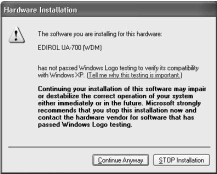
If the "What action do you want Windows to take?" setting was not set to "Ignore", a "Hardware Installation" dialog box will appear.
If "What action do you want Windows to take?" is set to "Warn",
- Click [Continue Anyway].
- Continue the installation.
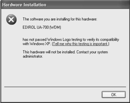
If "What action do you want Windows to take?" is set to "Block"
- Click [OK].
- When the "Found New Hardware Wizard" appears, click [Finish].
- Perform the installation as described in the "Troubleshooting" section on Device Manager shows "?", "!", or "USB Composite Device" (p. 242).
18
The Insert Disk dialog box will appear.
Click [OK].
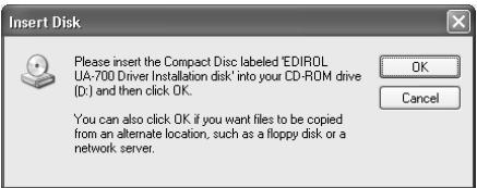
MEMO
The Insert Disk dialog may not appear. In that case, proceed to step 17.
19
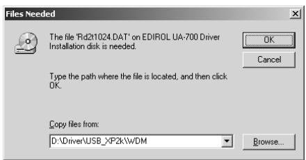
The Files Needed dialog box will appear. Input the following into the "Copy files from" field, and click [OK].
D:\Driver\USB_XP2K\WDM
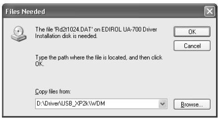
- The drive name “D:” may be different for your system. Specify the drive name of your CD-ROM drive.
MEMO
If you are using the MME driver, input MME instead of WDM.
If the "What action do you want Windows to take?" setting was not set to "Ignore", a "Hardware Installation" dialog box will appear.
If "What action do you want Windows to take?" is set to "Warn",
- Click [Continue Anyway].
- Continue the installation.
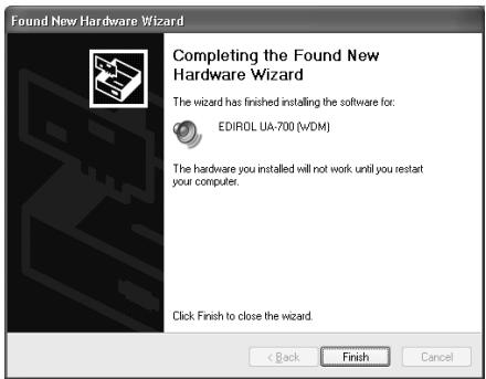
20
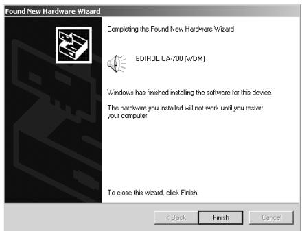
The Found New Hardware Wizard will appear.
Verify that "EDIROL UA-700 (WDM)" or "EDIROL UA-700 (MME)" is displayed, and click [Finish]. Wait until "Found New Hardware" appears near the taskbar.
21
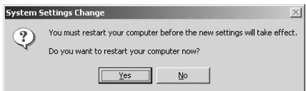
When driver installation has been completed, the System Settings Change dialog box will appear.
Click [Yes]. Windows will restart automatically.
If you changed "What action do you want Windows to take?"
If you changed the What action do you want Windows to take? setting, restore the original setting after Windows restarts.
- If you are using Windows XP Professional, log on to Windows using the user name of an administrative account (e.g., Administrator).
- Click the Windows start menu, and from the menu, select Control Panel.
-
In "Pick a category", click "Performance and Maintenance".
-
Depending on how your system is set up, the System icon may be displayed directly in the Control Panel (classic view). In this case, double-click the System icon.
-
In "or pick a Control Panel icon", click the System icon. The System Properties dialog box will appear.
- Click the Hardware tab, and then click [Driver Signing]. The Driver Signing Options dialog box will appear.
- Return the What action do you want Windows to take? setting to the original setting (either "Warn" or "Block"), and click [OK].
- Click [OK]. The System properties dialog box will close.
Next, you need to make the driver settings. ( Settings and checking (p. 33))
Windows 2000 users
1
With the UA-700 disconnected, start up Windows.
Disconnect all USB cables except for a USB keyboard and USB mouse (if used).
2
Log on to Windows as a user with administrative privileges (such as Administrator).
3
Open the System Properties dialog box.
Click the Windows Start button, and from the menu that appears, select Settings | Control Panel. In Control Panel, double-click the System icon.
NOTE
If the UA- 700 is alreadyconnected to yourcomputer and a message of
"Add New Hardware Wizard" is displayed, go to the included CD-ROM folder named
DRIVER\USB_XP2K\WDM or
DRIVER\USB_XP2K\MME, open the file
Readme_e.htm, and read the "Troubleshooting" section entitled "You attempted to install using the above procedure, but were not able to".

Click the Hardware tab, and then click [Driver Signature].
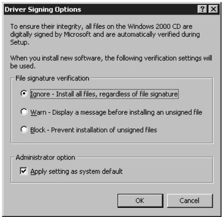
Open the Driver Signing Options dialog box.

Make sure that "File signature verification" is set to "Ignore".
If it is set to "Ignore", simply click [OK].
If it is not set to "Ignore", make a note of the current setting ("Warn" or "Block"). Then change the setting to "Ignore" and click [OK].
After installing the driver, restore the original setting.
( If you changed "File signature verification" (p. 26))

If you changed "File signature verification" in step 5, you must restore the previous setting after you have installed the driver. () If you changed "File signature verification" (p.26))

Click [OK] to close the System Properties dialog box.

Exit all currently running software (applications).
Also close any open windows. If you are using virus checking or similar software, be sure to exit it as well.

Insert the CD-ROM.
Insert the CD-ROM into the CD-ROM drive of your computer.

Click the Windows Start button. From the menu that appears, select "Run...".
Open the "Run..." dialog box.
10
In the dialog box that appears, input the following into the "Open" field, and click [OK].
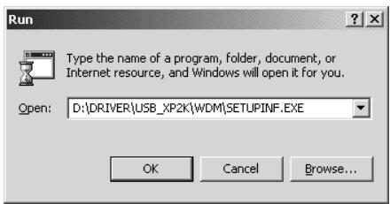
D:\DRIVER\USB_XP2K\WDM\SETUPINF.EXE
- The drive name “D:” may be different for your system. Specify the drive name of your CD-ROM drive.
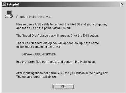
11
The SetupInf dialog box will appear.
You are now ready to install the driver.
12
Use the USB cable to connect the UA-700 to your computer.
- With the power switch turned OFF, connect the AC adaptor to the UA-700.
- Connect the AC adaptor to an electrical outlet.
- Use the USB cable to connect the UA-700 to your computer.
13
Set the UA-700's ADVANCE (mode select) switch to the ON position.
14
Set the UA-700's power switch to the ON position.
Near the task bar, your computer will indicate "Found New Hardware". Please wait.
MEMO
In this manual, the location of folders and files is given in terms of the file path, using \ as the delimiter. For example,
WDM\SETUPINF.EXE
indicates the
SETUPINF.EXE file found in the WDM folder.
MEMO
If you are using the MME driver, input MME instead of WDM.
MEMO
Once the connections have been completed, turn on power to your various devices in the order specified. By turning on devices in the wrong order, you risk causing malfunction and/or damage to speakers and other devices.
MEMO
This unit is equipped with a protection circuit. A brief interval (a few seconds) after power up is required before the unit will operate normally.
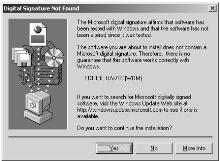
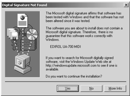
If the "File signature verification" setting was not set to "Ignore", a "Digital Signature Not Found" dialog box will appear.
If "File signature verification" is set to "Warn",
- Click [Yes].
- Continue the installation.
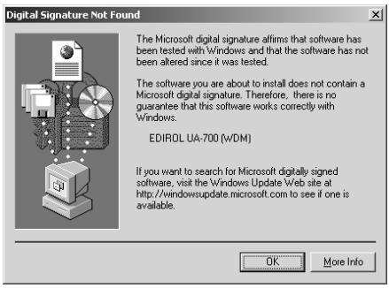
If "File signature verification" is set to "Block"
- Click [OK].
- When the "Found New Hardware Wizard" appears, click [Finish].
- Perform the installation as described in the "Troubleshooting" section on Device Manager shows "?", "! ", or "USB Composite Device" (p. 242).
15
The Insert Disk dialog box will appear.
Click [OK].
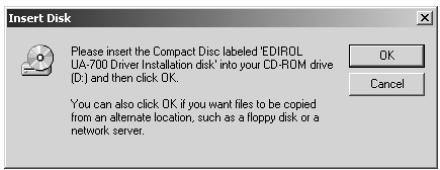
16
The Files Needed dialog box will appear.
In the Copy files from field, type the folder name that is shown in the dialog box, and click [OK].
D:\DRIVER\USB_XP2K\WDM
- The drive name “D:” may be different for your system. Specify the drive name of your CD-ROM drive.

If the Insert Disk dialog box does not appear, please read The "Insert Disk" dialog box does not appear (p. 242)

If you are using the MME driver, input MME instead of WDM.
If the "File signature verification" setting was not set to "Ignore", a "Digital Signature Not Found" dialog box will appear.
If "File signature verification" is set to "Warn",
- Click [Yes].
- Continue the installation.
17
The "Find New Hardware Wizard" may be displayed.
Verify that "EDIROL UA-700 (WDM)" or "EDIROL UA-700 (MME)" is displayed, and click [Finish].
If the "Find New Hardware Wizard" dialog box is not displayed, proceed to step 18.
18
The System Settings Change dialog box may appear.
Click [Yes]. Windows will restart automatically.
If the System Settings Change dialog box does not appear, restart Windows from the Start menu.
If you changed "File signature verification"
If you changed the "File signature verification" setting in step 5, restore the original setting after Windows restarts.
- After Windows restarts, log in to Windows as a user with administrative privileges, (such as Administrator).
- In the Windows desktop, right-click the My Computer icon, and from the menu that appears, select Properties. The System Properties dialog box will appear.
- Click the Hardware tab, and then click [Driver signature]. The Driver Signing Options dialog box will appear.
- Return the "File signature verification" setting to the original setting (either "Warn" or "Block"), and click [OK].
- Click [OK]. The System Properties dialog box will close.
Next, you need to make the driver settings.
( Settings and checking (p. 33))
Windows Me/98 users
1
With the UA-700 disconnected, start up Windows.
Disconnect all USB cables other than those for a USB keyboard or USB mouse.
2
Exit all currently running software (applications).
Also, close any open windows. If you are using a virus checker or similar software, be sure to exit this as well.
3
Prepare the CD-ROM.
Insert the CD-ROM into the CD-ROM drive of your computer.
4
Click the Windows Start button. From the menu that appears, select Run...
Open the Run... dialog box.

If the UA-700 is already connected to your computer and a message of "Add New Hardware Wizard" is displayed, go to the CD-ROM folder named DRIVER\USB_ME98, open the file Readme_e.htm, and read the "Troubleshooting" section entitled "You attempted to install using the above procedure, but were not able to".

In the dialog box that appears, input the following into the "Open" field, and click [OK].
D:\DRIVER\USB_ME98\SETUPINF.EXE
- The drive name “D:” may be different depending on your system. Type the name of your CD-ROM drive.

Open the SetupInf dialog box.
You are now ready to install the driver.

Use the USB cable to connect the UA-700 to your computer.
- With the power switch turned OFF, connect the AC adaptor to the UA-700.
- Connect the AC adaptor to an electrical outlet.
- Use the USB cable to connect the UA-700 to your computer.

Set the UA-700's ADVANCE (mode select) switch to the ON position.

Set the UA-700's power switch to the ON position.
Near the task bar, your computer will indicate "Found New Hardware". Please wait.

If you are using Windows 98, an Insert disk dialog box will appear.
Click [OK].


In this manual, the location of folders and files is given in terms of the file path, using \ as the delimiter.
For example, USB_ME98\SETUPINF. EXE indicates that the SETUPINF.EXE file is located in the USB_ME98 folder.

Once the connections have been completed, turn on power to your various devices in the order specified. By turning on devices in the wrong order, you risk causing malfunction and/or damage to speakers and other devices.

This unit is equipped with a protection circuit. A brief interval (a few seconds) after power up is required before the unit will operate normally.

If you are using Windows 98 and the Insert disk dialog box dose not appear, please read The "Insert Disk" dialog box does not appear (p.242).
11
The New Hardware Found dialog box will appear.
In the Copy files from field, type the folder name that is shown in the SetupInf dialog box, and click [OK].
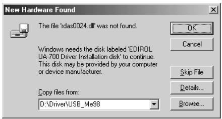
D:\DRIVER\USB_ME98
- The drive name “D:” may be different depending on your system. Type the name of your CD-ROM drive.
12
Once the driver has been installed, the New Hardware Found dialog box will close.
In the SetupInf dialog box, click [OK]. The SetupInf dialog box will close.
Next, you need to make the driver settings.
( Settings and checking (p. 33))
Installing the OS-standard driver
The procedure for installation and settings will depend on your system. Proceed to the appropriate section as follows.
- Windows XP/2000 users. (p. 28)
- Windows Me users. (p. 29)
- Windows 98 users. (p. 30)
Windows XP/2000 users
1
With the UA-700 disconnected, start up Windows.
Disconnect all USB cables except for a USB keyboard and USB mouse (if used).
2
Exit all currently running software (applications).
If you are using a virus checker or similar software, be sure to exit it as well.

If the New Hardware Found dialog box does not appear, re-install the driver using the same procedure as described in The "Insert Disk" dialog box does not appear (p. 242).

Use the USB cable to connect the UA-700 to your computer.
- With the power switch turned OFF, connect the AC adaptor to the UA-700.
- Connect the AC adaptor to an electrical outlet.
- Use the USB cable to connect the UA-700 to your computer.

Place the UA-700's ADVANCE (mode select) switch in the OFF position.

Advance mode is OFF

Set the UA-700's power switch to the ON position.
The UA-700 will be detected automatically, and the driver will be installed.

When installation is complete, restart Windows.
Next, you will need to make the driver settings. ( Settings and checking (p. 33))
Windows Me users

With the UA-700 disconnected, start up Windows.
Disconnect all USB cables except for a USB keyboard and USB mouse (if used).

Exit all currently running software (applications).
If you are using a virus checker or similar software, be sure to exit it as well.

Use the USB cable to connect the UA-700 to your computer.
- With the power switch turned OFF, connect the AC adaptor to the UA-700.
- Connect the AC adaptor to an electrical outlet.
- Use the USB cable to connect the UA-700 to your computer.

Place the UA-700's ADVANCE (mode select) switch in the OFF position.
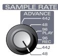
Advance mode is OFF
MEMO
Once the connections have been completed, turn on power to your various devices in the order specified. By turning on devices in the wrong order, you risk causing malfunction and/or damage to speakers and other devices.
MEMO
If you are using Windows XP, the installation has been completed when the message near the taskbar saying that "Found New Hardware" has disappeared.
MEMO
This unit is equipped with a protection circuit. A brief interval (a few seconds) after power up is required before the unit will operate normally.
MEMO
Once the connections have been completed, turn on power to your various devices in the order specified. By turning on devices in the wrong order, you risk causing malfunction and/or damage to speakers and other devices.

Set the UA-700's power switch to the ON position.

Windows will detect the UA-700, and the "Add New Hardware Wizard" dialog box will appear.
Make sure that Automatic search for a better driver (Recommended) is selected, and click [Next].
Add New Hardware Wizard
Windows has found the following new hardware:
USB Audio Device
Windows can automatically search for and install software on the computer. You can also use the Windows 3200 home computer to install media, insert it now and click Next.
What would you like to do?
Automatic search for a better driver (Recommended)
Specify the location of the driver (Advanced)

Driver detection will begin.

When the driver has been found, driver installation will begin.

Once the driver has been installed, a dialog box will inform you of this.
Click [Finish].

Restart Windows.
Add New Hardware Wizard

USB Audio Device
Windows has finished installing the new hardware device.
<Back
Finish
Cancel
Next, you will need to make the driver settings.
( Settings and checking (p. 33))
Windows 98 users
The USB composite device driver is installed first, then the USB audio device driver is installed. Use the following procedure to install the drivers.

With the UA-700 disconnected, start up Windows.
Disconnect all USB cables except for a USB keyboard and USB mouse (if used).

Exit all currently running software (applications).
If you are using a virus checker or similar software, be sure to exit it as well.

This unit is equipped with a protection circuit. A brief interval (a few seconds) after power up is required before the unit will operate normally.

Depending on your system, a certain amount of time may be required for the device to be detected after the driver has been installed.

Use the USB cable to connect the UA-700 to your computer.
- With the power switch turned OFF, connect the AC adaptor to the UA-700.
- Connect the AC adaptor to an electrical outlet.
- Use the USB cable to connect the UA-700 to your computer.

Place the UA-700's ADVANCE (mode select) switch in the OFF position.
Advance mode is OFF

Set the UA-700's power switch to the ON position.

USB composite device will be detected automatically, and the "Add New Hardware Wizard" dialog box will appear. Click [Next].
Add New Hardware Wizard
This wizard searches for new drivers for:
USB Composite Device
A device driver is a software program that makes a hardware device work.

Next
Cancel

When "What do you want Windows to do?" appears, select "Search for the best driver for your device (Recommended)", and click [Next].
Add New Hardware Wizard
What do you want Windows to do?
Search for the best driver for your device [Recommended].
Display a list of all the drivers in a specific location, so you can select the driver you want.

A dialog box like the one shown will appear.
Check CD-ROM drive, and click [Next]
Add New Hardware Wizard
Windows will search for new drivers in its driver database on your hard drive, and in any of the following selected locations. Click Next to start the search.
Floppy disk drives
√ CD-ROM drive
Microsoft Windows Update
Specify a location:

Next
Cancel

Once the connections have been completed, turn on power to your various devices in the order specified. By turning on devices in the wrong order, you risk causing malfunction and/or damage to speakers and other devices.

This unit is equipped with a protection circuit. A brief interval (a few seconds) after power up is required before the unit will operate normally.

If this dialog box does not appear, refer to "Find new hardware wizard" does not execute automatically (p. 241).

If the display indicates "Can't find an updated driver for this device", check "Updated driver", and click [Next].

A dialog box like the one shown will appear.
Click [Next].
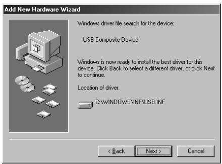

Depending on your system, the Driver
location may differ from the illustration, but this is not a problem.
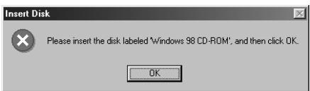
10
File (driver) copying will begin.
If the Windows CD-ROM is not inserted in the CD-ROM drive, a "Insert Disk" dialog box may appear. In this case, insert the Windows CD-ROM into the CD-ROM drive and click [OK].
11
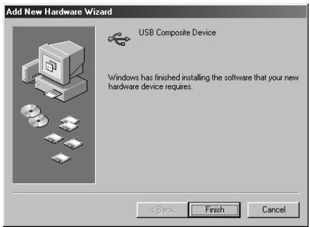
When installation of the USB Composite Device driver is completed, a dialog box like the one shown here will appear.
Click [Finish].
12
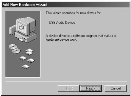
Next, the USB audio device will be detected automatically, and the "Add New Hardware Wizard" dialog box will appear.
Click [Next], and proceed with the installation in the same way as in steps 8-11 (p. 31).
13
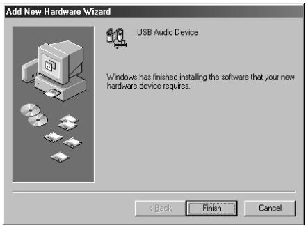
When installation of the USB audio device driver is complete, a dialog box like the one shown here will appear.
Click [Finish].
14
Installation of the USB composite device driver and USB audio device driver has been completed.
Restart Windows.
Next, you will need to make the driver settings.
( Settings and checking (p. 33))
Settings and checking
■ Specifying the audio and MIDI input/output destination
Windows XP/2000/Me users
1
Open Control Panel.
Click the Windows Start button, and from the menu that appears, select Settings | Control Panel.
Windows XP
Click the Windows start button, and from the menu that appears, select Control Panel.
2
Open the Sounds and Audio Devices Properties dialog box (or in Windows 2000/Me, Sounds and Multimedia Properties).
Windows XP
In “Pick a category”, click “Sound, Speech, and Audio Devices”. Next, in “or pick a Control Panel icon”, click the sounds and Audio Devices icon.
Windows 2000/Me
In Control Panel, double-click the Sounds and Multimedia icon to open the "Sounds and Multimedia Properties" dialog box.
MEMO
Depending on how your system is set up, the Sounds and Audio Devices icon may be displayed directly in the Control Panel (the Classic view). In this case, double-click the Sounds and Audio Devices icon
MEMO
If the Sound and Multimedia icon is not displayed, click "Show all control panel options" in the frame at the left.

Click the Audio tab.

For MIDI music playback, click the located at the right of [Default device] (or in Windows 2000/Me, [Preferred device]), and select the following from the list that appears.
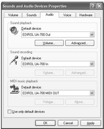
| Advanced mode | Standard driver mode | |
| Sound playback | EDIROL UA-700 OUT | EDIROL UA-700 (Windows XP) USB Audio Device (Windows 2000/Me) |
| Sound recording | EDIROL UA-700 IN | EDIROL UA-700 (Windows XP) USB Audio Device (Windows 2000/Me) |
| MIDI music playback | EDIROL UA-700 MIDI OUT | MIDI cannot be handled when using Standard Driver mode. |

- Close the Sounds and Audio Devices Properties dialog box.
- Click OK to complete the settings.
Proceed to the next section. ( Volume Control setting (p. 36))
Windows 98 users

Open Control Panel.
Click the Windows Start button, and from the menu that appears, select* Settings | Control Panel.

Open the Multimedia Properties dialog box.
In Control Panel, double-click the Multimedia icon to open the "Multimedia Properties" dialog box.

Click the Audio tab.

For details on Advanced mode and Standard Driver mode, refer to Advanced mode and Standard driver mode (p. 14).

Specify the "Preferred device". Click the Playback field and Recording field, make the following selections from the list that appears, and click [Apply].
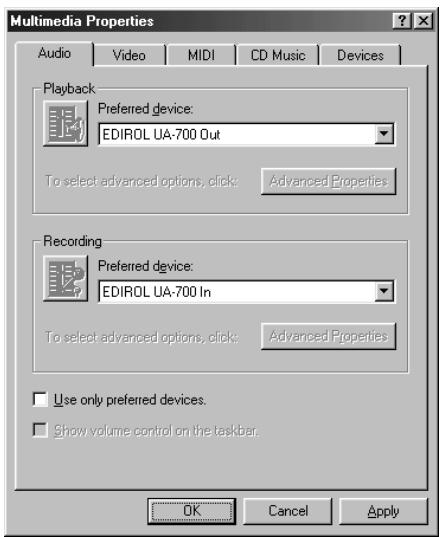
| Advanced mode | Standard driver mode | |
| Playback | EDIROL UA-700 Out | USB Audio Device |
| Recording | EDIROL UA-700 In | USB Audio Device |

Click the MIDI tab.

Set "MIDI output".
Select [Single instrument], and choose one of the following from the list that appears, and click [Apply].
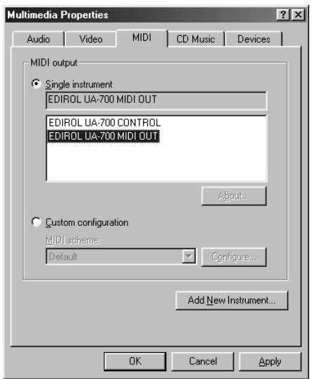
| Advanced mode | Standard driver mode | |
| MIDI output | EDIROL UA-700 MIDI OUT | MIDI cannot be handled when using Standard Driver mode. |

Close the Multimedia Properties dialog box.
Click [OK] to complete the settings.

For details on Advanced mode and Standard Driver mode, refer to Advanced mode and Standard driver mode (p. 14).

For details on Advanced mode and Standard Driver mode, refer to Advanced mode and Standard driver mode (p. 14).
This completes MIDI and audio input/output destination settings. If you installed the standard Windows driver, make settings for the Windows volume control.
Proceed to the next section. ( Volume Control setting (p. 36))
Volume Control setting
If you installed the standard Windows driver, set the Windows volume control.

Open the Volume Control.
Click the Windows Start button, and select Programs | Accessories | Entertainment | Volume Control.

Raise or lower the slider to adjust the volume of the UA-700.
If you have installed the Standard driver, the UA-700 can use the Windows volume control to adjust the output volume.
Items that can be set
| CD Player (CD Audio) | Controls the volume of “audio CDs” on the internal CD-ROM drive of the computer. (*1) |
| WAVE | Controls the volume of sound output from the “EDIROL UA-700” audio output device. Digital output and analog output will change. |
| Synthesizer SW Synth | Controls the volume of the software synthesizer built into Windows. |
*1
If the CD playback volume does not change when you adjust this control, then change the WAVE volume. If you are using Windows 2000 and the CD Player is not displayed, check "Enable digital music CDs for this CD playback device" in Digital CD Playback.
( When playing audio CDs from the computer's internal CD-ROM drive, or using the UA-700 to play game music (Standard driver mode only) (p. 37))

If the Volume Control is not installed on your computer, use the Control Panel icon Add or Remove Programs to install it. For details on installation, refer to the Windows manual or Help.

You will be able to use the UA-700 at the best audio quality if you set the Volume Control volume to the maximum setting.

If Mute is checked or if the slider is lowered all the way, no sound will be output from the UA-700.
When playing audio CDs from the computer's internal CD-ROM drive, or using the UA-700 to play game music (Standard driver mode only)
Windows XP/2000 users:
- Open the System Properties dialog box. Select Start | Settings | Control Panel, and in the Control Panel, double-click the System icon. (Windows XP- Click the Windows start button, and from the menu that appears, select Control Panel.)
- Open the Device Manager. Click the Hardware tab, and click the Device Manager button.
- Open the CD-ROM drive's Properties. In CD-ROM drive, double-click the CD-ROM drive that you are using. In Digital CD Playback, check the "Enable digital CD audio for this CD-ROM device" item.
Windows Me users:
- Open System Properties. Select Start | Settings | Control Panel, and in Control Panel, double-click the System icon.
- Open the CD-ROM drive's Properties. Double-click the CD-ROM icon, and then double-click the CD-ROM drive that you are using.
- Click the Properties tab, and in Digital CD Playback, check the "Enable digital CD audio for this CD-ROM device" item.
Windows 98 users:
- Open the Multimedia Properties dialog box. Select Start | Settings | Control Panel, and in Control Panel, double-click the Multimedia icon.
- Click the Music CD tab, and check the "Enable digital CD audio for this CD-ROM device" item.
Check whether there is sound
Now we will play back the sample data to check whether connections are correct.
Playing back the sample data
Here we will use standard Windows functionality to play back the sample data. The sample data is found on the CD-ROM.
1
Insert the CD-ROM into the CD-ROM drive of your computer.
2
From the Sample folder of the CD-ROM, drag Alright(.wav) to your desktop, copying it.
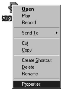
3
Right-click the copied file Alright(.wav), and select Properties (Play for Windows XP/2000/Me).
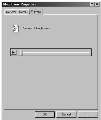
4
Play back the sample data.
Click the Preview tab, and then click the button.
Was the sample data played back?
If it was played back correctly, this means that the computer and the UA-700 are connected correctly, and that the drivers have been installed correctly.

In order to hear the sample data, you will need approximately 30 MB of free space on the hard disk in which Windows is installed.

Use of the song data supplied with this product for any purpose other than private, personal enjoyment without the permission of the copyright holder is prohibited by law. Additionally, this data must not be copied, nor used in a secondary copyrighted work without the permission of the copyright holder.

What you actually see on your computer screen may be different depending on your computing environment and the operating system your using.

If it did not play back correctly, refer to "Troubleshooting" (p. 240) to determine the reason. This section contains information on how to solve problems such as no sound, or failure to play back correctly.
Getting Connected and Installing Drivers (Macintosh)
If you are using a Windows computer, please proceed to Getting Connected and Installing Drivers (Windows) (p. 14).
What is a driver?
A "driver" is software that transfers data between the UA-700 and application software running on your computer, when your computer and the UA-700 are connected by a USB cable. The driver sends data from your application to the UA-700, and from the UA-700 to your application.
Advanced mode and Standard driver mode
The UA-700 has two operating modes, Advanced mode and Standard driver mode, and a different driver is used by each mode.
■ Advanced mode
The UA-700 will operate in this mode when the ADVANCE mode is turned ON. (→Refer to ADVANCE (mode select) switch (p. 125)) The special driver included on the CD-ROM will be used, allowing audio to be recorded/played/edited with high quality and stable timing.
In Advanced mode, audio signals can be transferred between the UA-700 and the computer at a resolution of 24 bits and sampling frequencies of 44.1 / 48 / 96kHz . Select Advanced mode if you are using an application that is able to record/playback/edit high-quality audio, such as a 24 bit audio application or an ASIO-compatible application such as Cubase VST, Logic Audio, and Metro. In Advanced mode, the UA-700 cannot play back audio data (audio CDs or warning sounds) from the Macintosh sound manager. ( Installing the special driver (p. 40))
Standard driver mode
The UA-700 will operate in this mode when the ADVANCE mode is turned OFF. (→Refer to ADVANCE (mode select) switch (p. 125)) The standard USB audio driver included with MacOS will be used. In standard driver mode, audio signals are transferred between the UA-700 and the computer at a resolution of 16 bits and sampling
frequencies of 44.1 / 48 kHz. Select this mode if you are using an application that uses MacOS's own functionality, such as an application that uses the computer's CD-ROM drive to play back CD-audio, or an application that uses the software synthesizer included with MacOS. The standard driver included with MacOS does not support ASIO.
Note also that the use of Mac OS 8.6 is not supported.
( Installing the OS-standard driver (p. 48))
Switching between Advanced mode and Standard driver mode
If you first install both the special driver and the standard driver, you will be able to switch between Advance and Standard driver modes by operating the UA-700's ADVANCE (mode select) switch.
- In order for the setting of the ADVANCE (mode select) switch to take effect, you must exit all sequencer software and other applications that use the UA-700, switch off the UA-700, then turn it back on again.
Installing the special driver
You must install the MIDI driver even if you will be using only audio on the UA-700. Be sure to install the MIDI driver.
Use either OMS or FreeMIDI as the MIDI driver.
If you are using OMS (p. 40)
If you are using FreeMIDI (p. 44)
-
Either OMS or FreeMIDI must be installed in your Macintosh, as appropriate for the sequencer software you are using.
-
If the power of the UA-700 is turned on, a message like the following will appear when the Macintosh is started up. Perform the steps described below as appropriate for the message that is displayed.
If the screen indicates:
"Driver required for USB device 'unknown device' is not available. Search for driver on the Internet?"
click [Cancel].
If the screen indicates:
"Software required for using device 'unknown device' cannot be found. Please refer to the manual included with the device, and install the necessary software"
click [OK].
■ Installing the UA-700 driver (OMS)
Use the following procedure to install the UA-700 driver.
The included UA-700 OMS driver is an add-on module for using the UA-700 with OMS. In order for you to use it, OMS must already be installed on the hard disk from which you started up.
If you would like to learn more about OMS, refer to OMS_2.3_Mac.pdf in the OMS Driver folder within the Driver E folder of the CD-ROM. You will need the Adobe Acrobat Reader in order to view OMS_2.3_Mac.pdf.
- Disconnect the UA-700 from the Macintosh before you perform the installation.

OMS can be found in the OMS Driver folder within the Driver E folder of the CD-ROM.
1
Exit all currently running software (applications).
If you are using a virus checker or similar software, be sure to exit this as well.
2
Prepare the CD-ROM.
Insert the CD-ROM into the CD-ROM drive.
3
Double-click the UA-700 OMS Driver-E Installer icon (found in the Driver E folder of the CD-ROM) to start up the installer.
4
Verify the Install Location, and click [Install].
5
If a message like the following is displayed, click [Continue].
The other currently running applications will exit, and installation will continue.

This installation requires your computer to restart after installing this software. Click Continue to automatically quit all other running applications. Click Cancel to leave your disks untouched.
Cancel
Continue
6
A dialog box will indicate Installation completed.
Click [Restart] to restart your Macintosh.
OMS settings
To check the OMS settings, you will first need to connect a MIDI sound module to the UA-700's MIDI OUT connector.
For details on connecting a MIDI sound module, refer to the owner's manual for your MIDI sound module.
1
Use the USB cable to connect the UA-700 to your computer.
- With the power switch turned OFF, connect the AC adaptor to the UA-700.
- Connect the AC adaptor to an electrical outlet.
- Use the USB cable to connect the UA-700 to your computer.
2
Set the UA-700's ADVANCE (mode select) switch to the ON position.
3
Set the UA-700's power switch to the ON position.

The indication for the installation location will differ depending on your system. Make sure that the startup disk for the system you are using is selected.

Once the connections have been completed, turn on power to your various devices in the order specified. By turning on devices in the wrong order, you risk causing malfunction and/or damage to speakers and other devices.

From the CD-ROM, drag the Driver E-OMS Setting folder into the Opcode-OMS folder on the hard disk of your Macintosh to copy it there.

DM5 Setting

In the Opcode-OMS Application folder where you installed OMS, double-click OMS Setup to start it up.

OMS Setup

If a dialog box like the one shown here appears, click [Turn It Off]. A confirmation dialog box will then appear, so click [OK].

AppleTalk
AppleTalk is on. It is used for connecting your computer to network services, such as file servers and printers. But it can make MIDI communication less reliable.
If you choose Turn It Off, don't disconnect AppleTalk yet.
CAUTION: GMS may not turn off AppleTalk as reliably as Apple's system software.
Options...
Leave It On
Turn It Off

The Create a New Studio Setup dialog box will appear.
Click [Cancel]. If you accidentally clicked OK, click [Cancel] in the next screen.
Create a New Studio Setup
A studio setup document is a list of your M1DI devices and cables between them.
You use it to tell applications what's in your studio.
Click OK to have OMS automatically locate your MIDI devices and build a new studio setup document.
Cancel
OK

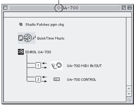
Choose "Open" from the File menu.
From the OMS Setting folder that you copied in step 4, select the UA-700 USB file, and click [Open].
A screen like the one shown here will appear.


This unit is equipped with a protection circuit. A brief interval (a few seconds) after power up is required before the unit will operate normally.

We recommend that you turn off AppleTalk, by selecting Chooser from the Apple menu.

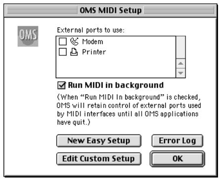
From the Edit menu, select OMS
MIDI Setup.
In the OMS MIDI Setup dialog box that appears, check Run MIDI in background, and click [OK].
10
From the File menu, choose Make Current.
If you are unable to select Make Current, it has already been applied, and you may continue to the next step.
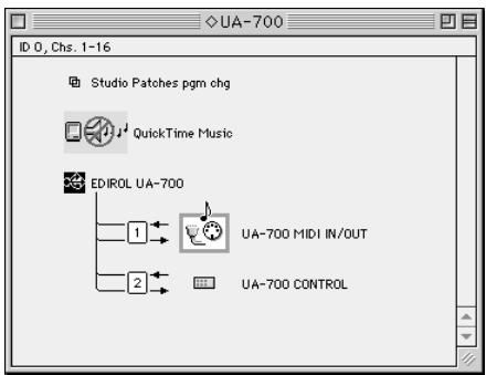
A diamond mark () indicated the settings are enabled.
11
Verify that MIDI transmission and reception can be performed correctly.
From the Studio menu, choose Test Studio.
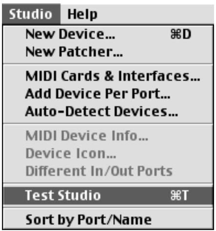
12
'When you move the mouse cursor near the sound generator icon, the cursor will change to a shape.
Click on the icon of each port in the diagram at right. If sound is heard from the sound module connected to the UA-700, the settings are correct.
13
Exit OMS Setup.
From the File menu, choose [Quit]. If the AppleTalk confirmation dialog box appears, click [OK] to close the dialog box.
This completes connections for the UA-700 and Macintosh, and installation of the MIDI driver.
Next, you need to install the ASIO driver.
( Installing the ASIO driver (p. 47))
■ Installing the UA-700 driver (FreeMIDI)
Use the following procedure to install the UA-700 driver. The included UA-700 FreeMIDI driver is an add-on module for using the UA-700 with FreeMIDI. In order to use it, FreeMIDI must be installed on the hard disk from which you started up.
- Disconnect the UA-700 from the Macintosh before beginning the installation.
1
Exit all currently running software (applications).
If you are using a virus checker or similar software, be sure to exit this as well.
2
Prepare the CD-ROM.
Insert the CD-ROM into the CD-ROM drive.
3
Double-click the UA-700 FM Driver - E Installer icon (found in the Driver E folder of the CD-ROM) to start up the installer.
4
Verify the Install Location, and click [Install].
5
If a message like the following is displayed, click [Continue].
The other currently running applications will exit, and installation will continue.

This installation requires your computer to restart after installing this software. Click Continue to automatically quit all other running applications. Click Cancel to leave your disks untouched.
Cancel
Continue
6
A dialog box will indicate Installation completed. Click [Restart] to restart your Macintosh.
FreeMIDI settings
To check the FreeMIDI settings, you will first need to connect a MIDI sound module to the UA-700's MIDI OUT connector.
For details on connecting a MIDI sound module, refer to the owner's manual for your MIDI sound module.
1
Use the USB cable to connect the UA-700 to your computer.
- With the power switch turned OFF, connect the AC adaptor to the UA-700.
- Connect the AC adaptor to an electrical outlet.
- Use the USB cable to connect the UA-700 to your computer.
2
Set the UA-700's ADVANCE (mode select) switch to the ON position.
3
Set the UA-700's power switch to the ON position.
4
From the CD-ROM, copy the Driver E - FreeMIDI Driver - Settings folder onto the hard disk of your Macintosh.
5
Open the FreeMIDI Applications folder from the location into which you installed FreeMIDI, and double-click the FreeMIDI Setup icon to start it up.
6
When "OMS is installed on this computer..." appears, click [FreeMIDI].
7
The first time the software is started up, a dialog box saying "Welcome to FreeMIDI!" will appear.
Click [Continue].
MEMO
Once the connections have been completed, turn on power to your various devices in the order specified. By turning on devices in the wrong order, you risk causing malfunction and/or damage to speakers and other devices.
MEMO
This unit is equipped with a protection circuit. A brief interval (a few seconds) after power up is required before the unit will operate normally.
8
When the FreeMIDI Preferences dialog box appears, click [Cancel].
9
When the About Quick Setup dialog box appears, click [Cancel].
10
From the File menu, choose Open.
11
Select UA-700 USB from the Settings folder you copied in step 3, and click [Open].
12
Verify that MIDI transmission and reception occur correctly.
13
From the MIDI menu, choose Check Connections.
14
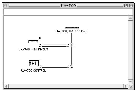
The mouse cursor will change to the shape of a keyboard. Click on the icon of each port in the diagram at right.
If sound is heard from the sound module connected to the UA-700, the settings are correct.
15
Once again choose the MIDI menu command Check Connections to end the test.
16
From the File menu, choose Quit to exit FreeMIDI Setup.
This completes connections for the UA-700 and Macintosh, and installation of the MIDI driver.
Next you will install the ASIO driver. ( Installing the ASIO driver (p. 47))
Installing the ASIO driver
You must install the MIDI driver even if you will be using only audio on the UA-700. Be sure to install the MIDI driver before you install the ASIO driver.
This section explains how to install the ASIO driver that allows the UA-700 to be used by your sequencer software or audio editing software. For details on installation and settings of the ASIO driver, be sure to also read the Driver E-ASIO Driver-Setting ASIO Driver-E.HTM document on the CD-ROM.
In Advanced mode, the UA-700 cannot play back audio data from the Macintosh's sound manager (such as audio CDs and alert sounds).
The ASIO driver of the UA-700 supports the following audio input/output channels.
Audio input.....24/16 bit 1 stereo ch. (2 monauralchs.)
Audio output.....24/16 bit 1 stereo ch. (2 monauralchs.)
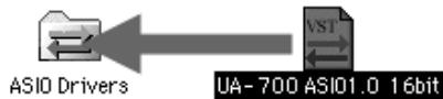
Here we will explain how to install the ASIO 1.0 16 bit-compatible driver.
If your ASIO-compatible software supports ASIO 2.0 or recording/playback of 24 bit audio data, using the following drivers will provide a higher quality environment.
| ASIO-compatible software | Driver to use | |
| ASIO2.0-compatible | 24 bit compatible | |
| × | × | UA-700 ASIO 1.0 16 bit |
| × | ○ | UA-700 ASIO 1.0 24 bit |
| ○ | × | UA-700 ASIO 2.0 16 bit |
| ○ | ○ | UA-700 ASIO 2.0 24 bit |
MEMO
ASIO (Steinberg Audio Stream In/Out Interface) This is an audio interface standard promoted by the Steinberg Corporation. When the UA-700 is used with ASIO-compatible software, the synchronization precision will be improved, allowing a more sophisticated music production environment.
1
From the Driver E-ASIO Driver folder of the CD-ROM, copy [UA-700 ASIO1.0 16bit] to the [ASIO Drivers] folder within the
ASIO Drivers folder of the ASIO-compatible software you are using (e.g., Cubase VST, Logic Audio, Digital Performer, Metro, or SPARK LE).
2
Start up your ASIO-compatible software (e.g., Cubase VST, Logic Audio, Digital Performer, Metro, or SPARK LE).
3
Open the Audio setting dialog box of your ASIO-compatible software, and select [UA-700 ASIO 16bit] as the ASIO Device.
MEMO
The Audio setting dialog box will be named differently depending on your software. For details refer to the manual of your software.
Installing the OS-standard driver
1
With the UA-700 disconnected, start up Mac OS.
2
Exit all currently running software (applications).
If you are using a virus checker or similar software, be sure to exit it as well.
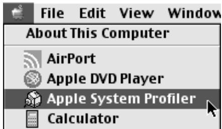
3
After starting up Mac OS, select Apple System Profiler from the Apple menu.
The "Apple System Profiler" dialog box will appear.
4
Click the Devices and Volumes tab.
5
Use the USB cable to connect the UA-700 to your computer.
- With the power switch turned OFF, connect the AC adaptor to the UA-700.
- Connect the AC adaptor to an electrical outlet.
- Use the USB cable to connect the UA-700 to your computer.
6
Set the UA-700's ADVANCE (mode select) switch to the ON position.

7
Set the UA-700's power switch to the ON position.
8
Wait for approximately five seconds.
The UA-700 will use the driver included with Mac OS.
While you are waiting, the screen display will not change, but the UA-700 is being detected. Do not touch the mouse or keyboard.

Once the connections have been completed, turn on power to your various devices in the order specified. By turning on devices in the wrong order, you risk causing malfunction and/or damage to speakers and other devices.

This unit is equipped with a protection circuit. A brief interval (a few seconds) after power up is required before the unit will operate normally.

In order to check that detection has been completed, once again go to "Apple System Profiler", and select "Update all
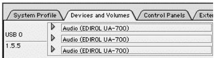
information" from the Commands menu.
In the USB area, three audio devices will be displayed.
If these are displayed correctly, driver installation has succeeded. In the File menu, click Quit to close "Apple System Profiler".
If they are not displayed correctly, disconnect the UA-700, wait for about ten seconds, and then repeat the procedure from step 2.
Next, you will need to make the driver settings.
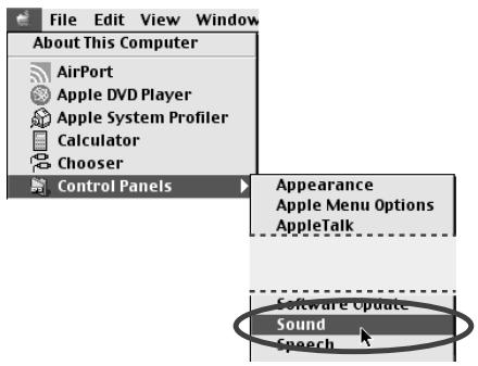
Settings the sound input/output

From the Apple menu, select Control Panel - Sound.
The Sound dialog box will appear.

The main volume slider will not move.

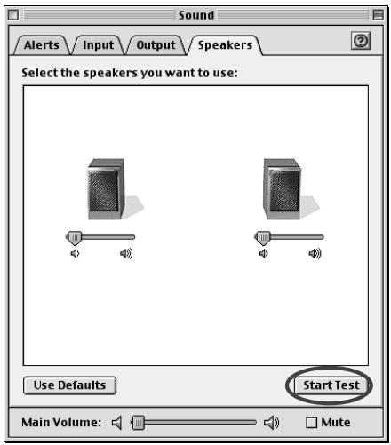
Click the Speakers tab or Speaker Settings.
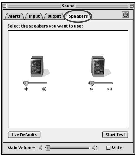

With the volume turned down on the UA-700 and on your peripheral audio equipment, click [Start Test].
Test signals will be output from the UA-700; left first, then right, as indicated in the screen.

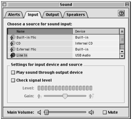
In the Sound dialog box, click the Input tab.
In Choose a source for sound input (Device), select USB audio.
- Do not check "Play sound through output device".

When you are finished making settings, close the Sound dialog box.
From the File menu, select Quit.

The output volume of the UA-700 cannot be adjusted with the Mac OS sound dialog box. Make volume adjustments through other means, such as on the speaker system you are using.

If USB audio is not displayed, close the "Sound" dialog box, and disconnect the UA-700's USB cable from the Macintosh. Perform the driver installation (p. 48) once again.
Windows XP-Anwender

Select the device driver you want to install for this hardware.

Select the manufacturer and model of your hardware device and then click Next. If you have a disk that contains the driver you want to install, click Have Disk.
Show compatible hardware
Model
EDIROL UA-700 (wDM)

driver is not digitally signed!
Tell me why driver signing is important
Disk
an
MEMO
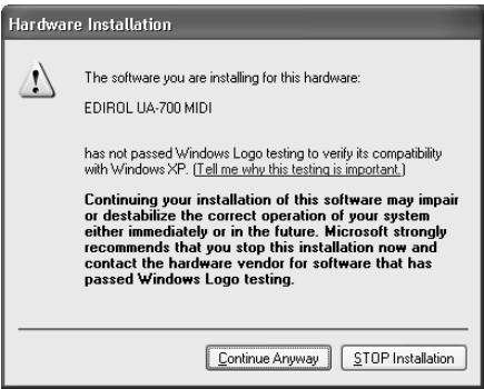
Hardware Installation

The software you are installing for this hardware:
EDIROL UA-700 (WDM)
has not passed Windows Logo testing to verify its compatibility with Windows XP. [Tell me why this testing is important.]
Continuing your installation of this software may impair or destabilize the correct operation of your system either immediately or in the future. Microsoft strongly recommends that you stop this installation now and contact the hardware vendor for software that has passed Windows Logo testing.
Continue Anyway
STOP Installation
Hardware Installation

The software you are installing for this hardware:
EDIROL UA-700 (WDM)
has not passed Windows Logo testing to verify its compatibility with Windows XP. [Tell me why this testing is important.]
This hardware will not be installed. Contact your system administrator.
OK
18
D:\Driver\USB_XP2K\WDM
Hardware Installation

The software you are installing for this hardware:
EDIROL UA-700 MIDI
has not passed Windows Logo testing to verify its compatibility with Windows XP. [Tell me why this testing is important.]
Continuing your installation of this software may impair or destabilize the correct operation of your system either immediately or in the future. Microsoft strongly recommends that you stop this installation now and contact the hardware vendor for software that has passed Windows Logo testing.
Continue Anyway
STOP Installation
20
The wizard has finished installing the software for:
EDIROL UA-700 (wDM)
The hardware you installed will not work until you restart your computer.
Click Finish to close the wizard.
Back Finish
21
Advanced mode and Standard driver mode (S.14).
MEMO
"Driver required for USB device 'unknown device' is not available. Search for driver on the Internet?"
"Software for using device 'unknown device' cannot be found. Please refer to the manual included with the device, and install the necessary software".
This installation requires your computer to restart after installing this software. Click Continue to automatically quit all other running applications. Click Cancel to leave your disks untouched.
Cance
Continue

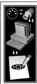
Create a New Studio Setup
A studio setup document is a list of your M1DI devices and cables between them.
You use it to tell applications what's in your studio.
Click OK to have OMS automatically locate your MIDI devices and build a new studio setup document.

Cancel
OK
A diamond mark () indicated the settings are enabled.
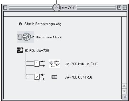

Different In/Out Ports
Test Studio
第T
Sort by Port/Name
12
This installation requires your computer to restart after installing this software. Click Continue to automatically quit all other running applications. Click Cancel to leave your disks untouched.
Can
Continue
6
Hardware Installation

The software you are installing for this hardware:
EDIROL UA-700 (WDM)
has not passed Windows Logo testing to verify its compatibility with Windows XP. [Tell me why this testing is important.]
Continuing your installation of this software may impair or destabilize the correct operation of your system either immediately or in the future. Microsoft strongly recommends that you stop this installation now and contact the hardware vendor for software that has passed Windows Logo testing.
Continue Anyway
STOP Installation
Hardware Installation

The software you are installing for this hardware:
EDIROL UA-700 (WDM)
has not passed Windows Logo testing to verify its compatibility with Windows XP. [Tell me why this testing is important.]
This hardware will not be installed. Contact your system administrator.
OK
18
Please insert the Compact Disc labeled 'EDIROL'
UA-700 Driver Installation disk' into your CD-ROM drive
[D:] and then click OK.
You can also click OK if you want files to be copied from an alternate location, such as a floppy disk or a network server.
Si la boite
Cancel
D:\Driver\USB_XP2K\WDM
This installation requires your computer to restart after installing this software. Click Continue to automatically quit all other running applications. Click Cancel to leave your disks untouched.
Cancel
Continue
6
A diamond mark () indicated the settings are enabled.
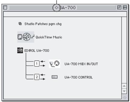
11
This installation requires your computer to restart after installing this software. Click Continue to automatically quit all other running applications. Click Cancel to leave your disks untouched.
Cane
Continue
6
D:\Driver\USB_XP2K\WDM
"Driver required for USB device 'unknown device' is not available. Search for driver on the Internet?"
,farecliscu[Cancel.]
"Software required for using device 'unknown device' cannot be found. Please refer to the manual included with the device, and install the necessary software".
fareclcusu[OK].
This installation requires your computer to restart after installing this software. Click Continue to automatically quit all other running applications. Click Cancel to leave your disks untouched.
Cancel
Continue
6
A diamond mark () indicated the settings are enabled.


This installation requires your computer to restart after installing this software. Click Continue to automatically quit all other running applications. Click Cancel to leave your disks untouched.
Cane
Continue
6
Dalla cartella Driver E-ASIO
This section explains the function and use for each part of the UA-700.
Names of things and what they do
The following introduces the various knobs, switches, etc., and explains what they do.
Panel
The UA-700 can be divided into the main control section, and four control sections for specific purposes. The explanation here is organized by these control sections, and explains the names and functions of each section.
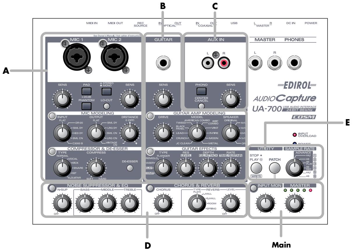
- Main. Main control. (p. 116)
A.Mic control. (p. 117)
B.Guitar control (p. 120)
C. Line control. (p. 123)
D. System Effect control. (p. 123)
E. Utility (p. 125)
Only one at a time!
Effects cannot be simultaneously applied to Mic control, Guitar control, and Line control. However, System Effect control can be used to apply an effect to all inputs. ( see Block diagram (p. 145))
Not available at 96 kHz!
If you are using 96 kHz, you cannot apply effects other than COMPRESSOR & DE-ESSER and NOISE SUPPRESSOR & EQ.
Main control
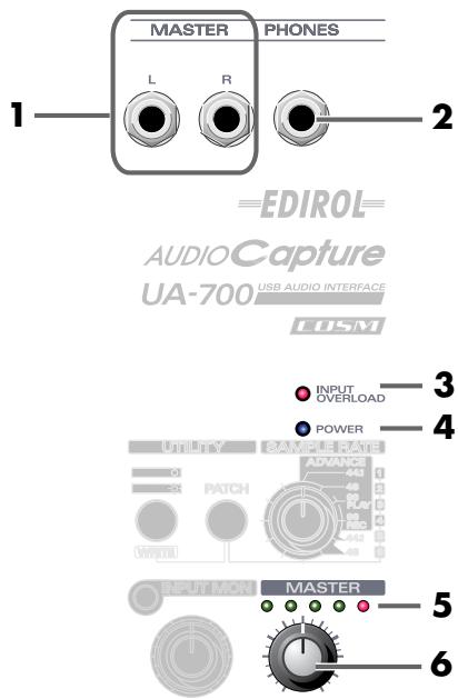
1. Master output jacks (phone type)
These are analog audio output jacks. They output the same sound as the master output jacks on the rear panel (RCA phono type). Use the set of jacks that is appropriate for the device you are connecting or the cables you are using.
2. Headphones jack
You can connect a set of headphones to this jack. The headphones jack will output the same sound as the master output jacks, the coaxial digital output jack, and the optical digital output jacks. Even if headphones are connected, sound will still be output from the master output jacks.
3. Input peak indicator
This lets you check whether distortion is occurring in the sound that is input from the mic input jacks, guitar input jack, or line input jacks. Adjust the input sensitivity knobs for each input so that the peak indicator does not light.
4. Power indicator
When you turn on the power switch, this indicator will blink for several seconds, and then remain lit.
5. Output level indicator
The number of LEDs that blink changes in accord with the output level, adjusted using the MASTER knob. If the red LED at the far right lights, use the master knob to lower the volume.
6. Master knob (MASTER)
This adjusts the final overall volume. It controls the volume of the digital output jacks, headphone jack, master output jacks (phone type), master output jacks (RCA phono type), coaxial digital output jacks, and optical digital output jacks.
■ Input monitor section
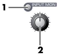
1. Input monitor switch
This switches whether the input signal from the mic input jacks, guitar input jack, line input jacks, and digital input jack will be output from the headphone jack, master output jacks, and digital output jacks.
If this switch is on, the input signal will be output. If this switch is off, the input signal will not be output. Turn this off (dark) if the audio data is being
"thru-ed" within your computer, or if you have connected a mixer and are outputting the input signal directly from your mixer for monitoring. The volume you adjust here will not affect the recording level.
- The input monitoring on/off state can be controlled directly from an ASIO 2.0 compatible application such as Cubase.
2. Input monitor volume
This knob adjusts the volume of the input signal from the mic input jacks, guitar input jack, line input jacks, and digital input jacks that is output from the headphone jack or master output jacks.
If this knob is set to the

position, the volume will be the same as the signal being recorded.
A. Mic control
Mic input section
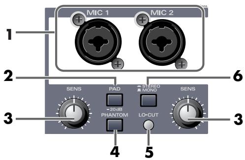
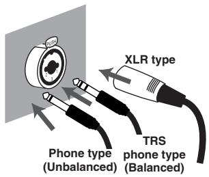
1. Mic input jacks (MIC1, MIC2)
These are input jacks for analog audio signals. You can use either XLR type or phone type connectors, depending on the device you are connecting. Either balanced or unbalanced connections may be used. 48V phantom power can be supplied to the XLR type connector, allowing you to use phantom-powered condenser mics. In this case, turn on the Phantom power switch.
- This instrument is equipped with balanced (XLR/TRS) type input jacks. Wiring diagrams for these jacks are shown at right. Make connections after first checking the wiring diagrams of other equipment you intend to connect.

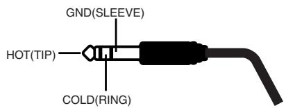
- Always turn the phantom power off when connecting any device other than condenser microphones that require phantom power. You risk causing damage if you mistakenly supply phantom power to dynamic microphones, audio playback devices, or other devices that don't require such power. Be sure to check the specifications of any microphone you intend to use by referring to the manual that came with it.
(This instrument's phantom power: 48 V DC, 10 mA Max)
2. Gain select switch (PAD -20 dB)
This switches the input level of the Mic input jacks.
Turn this off if you have connected a device that has low output gain.
3. Input sensitivity knobs
These adjust the input level of the mic input jacks.
4. Phantom power switch (PHANTOM 48V)
This is an on/off switch for the phantom power that is supplied to the XLR type mic input jacks.
- You must switch this off if a device not using phantom power is connected to the XLR type jacks, since supplying phantom power to such a device will cause malfunction.
5. LO-CUT switch
This lets you make a clearer recording by cutting pop noise (which can occur when a performer blows on the mic) and unwanted low-frequency "rumble".
6. STEREO/MONO select switch
This selects whether the input from the Mic input jacks will be handled as stereo or monaural. If you select stereo mode, MIC 1 will be recorded on the left channel, and MIC 2 on the right channel. If you select monaural mode, MIC 1 and MIC 2 will be mixed, and the same signal will be recorded on the left channel and right channel.
■ Mic effect section/Mic modeling
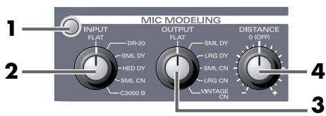
This section can transform the character of an inexpensive general-purpose mic into the character of an expensive studio mic (microphone -> microphone conversion).
Similar transformations can be applied to change the type of mic and apparent distance from the audio source. You can also add the character of a specific type of mic to an instrument that you are recording from line input (line -> microphone conversion).
1. Mic modeling switch
Switches mic modeling on/off. If this is off, mic modeling will be bypassed.
2. Input mic type selector knob
Selects the type of mic you are using for recording.
| FLAT | Line input |
| DR-20 | Roland DR-20 (a dynamic mic manufactured by Roland) |
| SML DY | A small dynamic mic used for instruments and vocals |
| HED DY | A headset-type dynamic mic |
| SML CN | An ultra-compact condenser mic |
| C3000 B | AKG C3000B (a condenser mic manufactured by AKG) |
3. Output mic type selector knob
Selects the type of mic you want to simulate.
| FLAT | A mic with a flat frequency response. Use this when you want to eliminate the idiosyncrasies of the mic used for recording. |
| SLM DY | A dynamic mic widely used for instruments and vocals. Ideal for a guitar amp or snare drum. |
| LRG DY | A dynamic mic with an extended low-frequency range. Suitable for bass drum or toms. |
| SML CN | A condenser mic for instruments, characterized by a bright-sounding upper range. Suitable for metallic percussion and acoustic guitar. |
| LRG CN | A condenser mic with a flat response. Suitable for vocals, narrations, and acoustic instruments. |
| VINTAGE CN | A vintage condenser mic. Suitable for vocals and acoustic instruments. |
- If you select a condenser-type mic model for OUT, the low-frequency range will be extended, which may cause low-frequency rumble transmitted through the mic stand to be emphasized. In such cases, either use the LO-CUT switch to cut the unwanted low-frequency range, or attach an isolation mount (a mic holder that uses rubber bands to absorb vibration) to your mic stand when you record.
4. Distance knob
This knob models the distance from the audio source to the mic. The simulated distance will be closer as you turn the knob toward the right (+), or farther if you move it toward the left (-).
■ Mic effect section/Compressor & De-esser
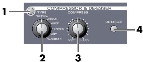
A compressor is an effect that makes the volume more consistent by compressing high input levels and boosting low input levels.
A de-esser is an effect that cuts the sibilants from a vocal, producing a softer tone.
1. Compressor/De-esser switch
Switches the compressor/de-esser on/off. The effects will be bypassed if this is off.
2. Compressor type select knob
Selects the type of compressor that is most suitable for the source you are recording.
- If you want to adjust the parameters with greater precision, refer to Compressor/De-esser section (p. 139), under “Advanced applications”.
| NORMAL | Light compression suitable for recording most instruments or vocals on a demo tape. | |
| Ratio | medium (2.8 : 1) | |
| Attack | medium | |
| Release | very fast | |
| VOCAL | Heavier compression suitable for recording a powerful vocal. | |
| Ratio | extremely high (∞ : 1) | |
| Attack | extremely fast | |
| Release | slow | |
| KICK | Compression suitable for recording a bass drum. Produces a percus-sive sound with a strong sense of attack. | |
| Ratio | extremely high (16 : 1) | |
| Attack | slow | |
| Release | medium | |
| SNARE | Compression suitable for recording a snare drum. Produces a powerful and heavy sound. | |
| Ratio | high (8 : 1) | |
| Attack | fast | |
| Release | fast | |
| KIT | Compression suitable for recording an entire drum kit. | |
| Ratio | medium (4:1) | |
| Attack | medium | |
| Release | medium | |
| A.GUITAR | Compression suitable for recording an acoustic guitar. Smoothly controls the sound, producing a natural effect when reverb or chorus are applied. | |
| Ratio | low (2:1) | |
| Attack | fast | |
| Release | medium | |
| Attack | The time from when the input level exceeds the threshold level until the effect is applied. |
| Release | The time from when the input level falls below the threshold level until the effect ceases to be applied. |
| Ratio | The ratio by which the level is compressed when the signal exceeds the threshold level. High ratio settings will produce sharp compression, and low settings will produce gentle compression. |
3. Compressor level knob
Controls the depth of compression. Turning this toward HARD will produce a stronger effect. This knob controls the threshold level (the level at which the effect begins to be applied) and the compressor output level.
4. De-esser switch
Switches the de-esser on/off.
- The effect will depend on the compressor type. The strongest effect is obtained with VOCAL.
B. Guitar control
■Guitar input section
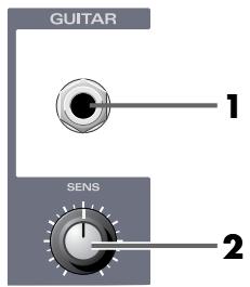
1. Guitar input jack
This is a high-impedance input jack for guitar. You can connect a guitar or bass directly to this jack.
2. Input sensitivity knob
This knob adjusts the input level.
■Guitar Amp Modeling section
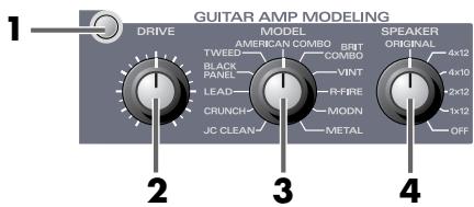
Using COSM technology, the Model knob simulates characteristics of a guitar amp, and the Speaker knob simulates the speaker size and cabinet configuration.
1. Guitar Amp Modeling switch
Switches the Guitar Amp Modeling on/off. The effect is bypassed if this switch is off.
2. Drive knob (DRIVE)
Adjusts the degree of distortion. Turning this knob clockwise will produce stronger distortion.
As desired, you can also modify the tone in other ways. ( Advanced applications (p. 138))
3. Model knob (MODEL)
Selects the type of guitar amp.
| Type | Character |
| JC CLEAN | The sound of a Roland JC-120. |
| CRUNCH | A naturally distorted crunch sound. |
| LEAD | Powerful, high-gain metal sound. |
| BLACK PANEL | Models a Fender Twin Reverb. |
| TWEED | Models a Fender Bassman 4 x 10" combo. |
| AMERICAN COMBO | Models a MESA/Boogie combo amp. |
| BRIT COMBO | Models the lead sound of a VOX AC-30TB. |
| VINT (VINTAGE STACK) | Models the input 1 sound of a Marshall 1959. |
| R-FIRE (R-FIRE STACK) | Models the RED channel of a MESA/Boogie DUAL Rectifier. |
| MODN (MODERN STACK) | Models a Soldano SLO-100. |
| METAL (METAL STACK) | Models the lead channel of a Peavey EVH5150. |
4. Speaker cabinet knob (SPEAKER)
Selects the type of speaker cabinet.
If you select ORIGINAL, the most suitable type of speaker cabinet for the selected type of guitar amp will be chosen automatically.
| Type | Character |
| ORIGINAL | The speaker(s) provided by the amp you selected in MODEL |
| 4 x 12” | A sealed speaker cabinet with four 12-inch speakers, ideal for large amps |
| 4 x 10” | An open-back speaker cabinet with four 10-inch speakers, with a unique sound |
| 2 x 12” | A typical open-back speaker cabinet with two 12-inch speakers |
| 1 x 12” | A small open-back speaker cabinet with one 12-inch speaker |
| OFF | Speaker cabinet modeling will not be performed. |
■Guitar effect section
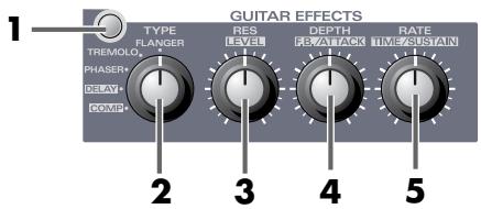
1. Guitar effect switch
Switches the guitar effect on/off.
2. Effect type select knob
Select either Flanger, Tremolo, Phaser, Delay, or Compressor.
The function of Effect control knobs 1, 2, and 3 will depend on the effect you choose.
Immediately after you select an effect, the parameters of that effect will be set to the factory settings.
If you want to adjust the effect, use the Effect control knobs described below.
3. Effect control knob 1 (RES)
4. Effect control knob 2 (DEPTH)
5. Effect control knob 3 (RATE)
Flanger
Produces a flanging effect which gives a "twisting" character to the sound.
| Effect control knob 1 | Resonance | Adjusts the amount of resonance (amount of feedback). Turning the knob clockwise produces a stronger and more distinctive effect. |
| Effect control knob 2 | Depth | Adjusts the depth of modulation. |
| Effect control knob 3 | Rate | Adjusts the speed of modulation. |
Tremolo
An effect that cyclically varies the volume.
| Effect control knob 1 | Phase | Spreads the tremolo to left and right. Turning this knob clockwise will produce a greater spread between left and right. |
| Effect control knob 2 | Depth | Adjusts the depth of the effect. |
| Effect control knob 3 | Rate | Adjusts the rate of modulation. |
Phaser
An effect that adds a phase-shifted sound to the direct sound, creating a phaser effect that produces a sense of rotation.
| Effect control knob 1 | Resonance | Adjusts the amount of resonance (amount of feedback). Increasing this value will produce a strong and more distinctive effect. |
| Effect control knob 2 | Depth | Adjusts the depth of rotation. |
| Effect control knob 3 | Rate | Adjusts the rate of rotation. |
Delay
Adds a delayed sound to the direct sound, creating a sense of greater depth.
| Effect control knob 1 | Level | Adjusts the volume of the delayed sound. |
| Effect control knob 2 | Feedback | Adjusts the amount of delayed sound that is returned to the input of the delay. Turning this knob clockwise will increase the number of delay repeats. |
| Effect control knob 3 | Delay time | Adjusts the delay time. |
Compressor
This is an effect that makes the level more consistent by compressing loud sounds and boosting soft sounds, sustaining the sound without distorting it.
| Effect control knob 1 | Level | Adjusts the volume. |
| Effect control knob 2 | Attack | Adjusts the strength of the picking attack. Turning this knob clockwise will sharpen the attack, producing a crisp sound. |
| Effect control knob 3 | Sustain | Specify the range (time) for which low-level signals will be boosted to a fixed volume. Turning this knob clockwise will produce longer sustain. |
C. Line control
Line input section
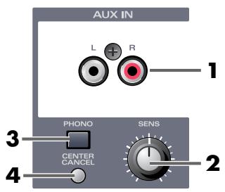
1. Line input jacks
Use these jacks to input audio signals from an audio device or MIDI sound module.
2. Input sensitivity knob
Adjusts the input level.
3. Phono equalizer switch
This switch turns on the built-in phono equalizer. This allows you to directly connect a record player. If you are using a record player with a built-in equalizer, leave this switch turned off.
-
Depending on your system, this may be affected by noise from your computer.
-
Connect the UA-700's grounding terminal (p. 128) to the grounding terminal of your record player.
- Connect your computer and the UA-700 to separate electrical outlets.
- Correctly ground your computer. (Refer to the owner's manual for your computer.)
4. Center cancel switch
This switch erases the signals localized at the center of the stereo signal that is input. This function is useful when you are creating karaoke data.
- In some cases, such as when effects have been applied to the signal, it may not be possible to erase the center signal.
- Since this processing avoids canceling the bass drum and bass guitar, it may not be possible to erase the vocal from the song if it contains a large amount of low-frequency components.
D. System effect control section
■ Noise Suppressor/Equalizer section
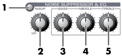
1. Noise Suppressor/Equalizer switch
Switches the noise suppressor/equalizer on/off. The effects are bypassed when this switch is off.
Noise suppressor
This effect suppresses the hum and noise that are picked up by a guitar pickup or microphone. Since the noise is reduced according to the envelope (volume change) of the input sound, a natural effect is obtained with virtually no change to the input sound.
2. Noise suppressor sensitivity knob
Adjusts the threshold level according to the level of the noise. If the noise is loud, turn this knob clockwise. Adjust the knob so that the decays of the input signal will sound natural.
- High settings of the threshold control may cause the beginning or end of notes to sound unnatural, and you may hear no sound at all if the volume control of your guitar is turned down.
Equalizer/Tone controls
These adjust the tonal character.
3. Bass knob (BASS)
Adjusts mainly the lower range.
4.Middle knob (MIDDLE)
Adjusts mainly the midrange.
5. Treble knob (TREBLE)
Adjusts mainly the upper range.
Chorus/Reverb section
Chorus
This effect adds a slightly modulated sound to the direct sound, creating beautiful spaciousness and depth.
Reverb
This effect adds the reverberation that is characteristic of performing in a concert hall.
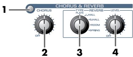
1. Chorus/Reverb switch
Switches chorus/reverb on/off. The effects are bypassed when this switch is off.
2. Chorus level knob
Adjusts the volume of the effect sound.
3. Reverb Type select switch
Selects the type of reverb. A variety of acoustical spaces can be simulated, depending on the knob's setting.
| Type | Character |
| Plate (PLATE) | Simulates a plate reverb unit. (A reverb device that uses the vibrations of a metal plate.) This is characterized by a metallic resonance with an extended high-frequency range. |
| Large Hall (L. HALL) | Simulates the reverberation of a concert hall. This produces a mild and spacious reverberation. |
| Small Hall (S. HALL) | Simulates the reverberation of a small concert hall. This produces a soft and clear reverberation. |
| Room (ROOM) | Simulates the reverberation of a room. This produces bright-sounding reverberation typical of a large room. |
| Spring (SPRING) | Simulates the spring reverb unit that is built into some guitar amps. |
4. Reverb Level knob
Adjusts the volume of the reverb sound.
E. Utility section
Sample rate/Patch select
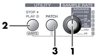
1. Sample rate select switch
This selects the sample rate (sampling frequency) that is used when recording or playing audio signals. In order for this setting to take effect, you must exit all applications, switch off the UA-700, then turn it on again.
( Using the sample rate select switch (p. 129))
ADVANCE (mode select) switch
The sample rate select switch is also used as the ADVANCE (mode select) switch that specifies the operating mode when the UA-700 is connected to your computer.
ADVANCE ON (Advanced mode)
Set the switch to the ADVANCE 44.1, 48, 96 PLAY, or 96 REC position.
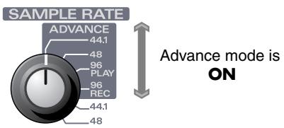
ADVANCE OFF (Standard driver mode)
Set the switch to the 44.1 or 48 position.
Advance mode is OFF
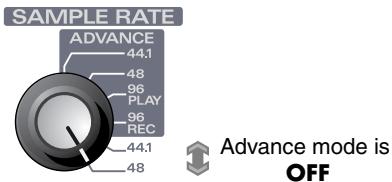
For details on the driver, refer to Getting Connected and Installing Drivers (Windows) (p. 14), or Getting Connected and Installing Drivers (Macintosh) (p. 39).
2. Sequencer control switch
This switch controls the playback of your sequencer. If you press this switch when it is dark, the switch will light and your sequencer will begin playing. If you press this switch when it is lit, it will go dark and your sequencer will stop.
In order to enable this switch, you will need to make settings on your sequencer.
( refer to Sequencer control switch settings (p. 143))
- The method of making these settings will depend on the version of your sequencer. Also, some sequencers may not support remote control. For details, check the manual of your sequencer.
3. Patch Mode switch
The UA-700 lets you save the current state of the effect settings into one of six patches, and load them at any time. This switch is used in conjunction with the Sequencer control switch and the Sample rate select switch to save and load patches.
Sample rate select switch specifies the patch number
Sequencer control switch . saves the patch
- Loading a patch
On the UA-700, the settings of the mic modeling section, compressor & de-esser section, guitar amp modeling section, guitar effect section, noise suppressor & equalizer section, reverb & chorus section, LO-CUT switch, and center cancel switch settings can be loaded from one of six patches.
- After a patch has been read, the settings will not match the positions of the panel knobs. Be aware of this when continuing to adjust the settings.
- Press the Patch Mode switch.
The Patch Mode switch will blink, and the UA-700 will be ready to load a patch.
- Turn the Sample rate/patch select switch to select the patch (number) that you want to load.
If you press any switch other than the Patch Mode switch, the Patch Mode switch will go dark. You will exit Patch mode and return to the previous state; i.e., the state prior to beginning the patch loading process. - Press the Patch Mode switch.
The Patch Mode switch will blink more rapidly, and will go dark when the patch has been loaded.
When you load a patch, all parameters of the patch will be transmitted to your computer in the form of a bulk dump. You can record this bulk dump into your sequencer software in order to save UA-700 patch parameters on your computer. In your sequencer software, select [EDIROL UA-700 CONTROL] as the MIDI port.
Saving a patch
On the UA-700, the settings of the mic modeling section, compressor & de-esser section, guitar amp modeling section, guitar effect section, noise suppressor & equalizer section, reverb & chorus section, Lo-Cut switch, and center cancel switch settings can be saved into one of six patches.
- Use the knobs of each section to create the desired sound.
- Hold down the Patch Mode switch, and press the Sequencer Control switch.
The Patch Mode switch will light, and the Sequencer Control switch will blink, indicating that the UA-700 is ready to save a patch. The current settings of the panel knobs and switches can now be saved.
3. Turn the Sample Rate/Patch Select knob to select the patch (number) that you want to save.
- If you press any switch other than the Sequencer Control switch, the Patch Save operation will be cancelled. The Patch Mode switch will go dark, and you will exit Patch mode.
- Press the Sequencer Control switch.
The Sequencer Control switch will blink more rapidly, and will go dark when the patch has been saved.
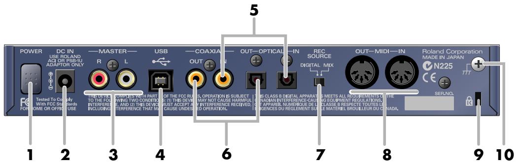
1. Power switch
Press this switch to turn the power on/off. The power is on when the switch is pressed inward.
2. AC adaptor jack
Connect the included AC adaptor to this jack. Insert the plug firmly so it won't get unplugged accidentally.
3. Master output jacks (RCA phono type)
These are output jacks for analog audio signals. They output the same sound as the Master output jacks (phone type) located on the panel. Use the set of jacks that is appropriate for the device or cable you are using.
4. USB connector
Use a USB cable to connect this to your computer.
- Do not connect or disconnect the USB cable while an audio playback application is running. Doing so may cause the application to hang up.
5. Coaxial digital input jack/Optical digital input jack
Use these jacks for digital input from a CD/MD/DAT. If a digital device is connected to the Optical digital input jack, the Optical digital input jack will take priority, and no signal will be input from the Coaxial digital input jack.
6. Coaxial digital output jack/Optical digital output jack
Use these jacks for digital connections to a digital audio device such as a DAT or MD.
7. Recording source select switch
This switch selects the input signal that will be sent via USB to your computer as the recording source.
| DIGITAL | Only the input from the digital input jack (coaxial or optical) will be sent to the computer. * Use the DIGITAL setting if you want to input digital data from a CD or MD. In this case, the various effect settings will be ignored, and only the original data will be input, without any possibility for noise to be added. |
| MIX | The input from all inputs (including the digital input jack) will be sent to the computer. |
8. MIDI IN/OUT connectors
Connect these to the MIDI connectors of other MIDI devices to allow MIDI messages to be exchanged with your computer.
9. Security Slot (R)
http://www.kensington.com/
10. Grounding terminal
Depending on the conditions under which you use the UA-700, noise may appear in the audio signal. If this occurs, you may be able to solve the problem by connecting this terminal to an external ground connection.
- Unsuitable places for connection
Water pipes (may result in shock or electrocution)
Gas pipes (may result in fire or explosion)
- Telephone-line ground or lightning rod (may be dangerous in the event of lightning)
Noise may also appear in the sound when a record player is connected. If this occurs, connect this terminal to the grounding terminal of your record player. For details, refer to Line input section (p. 123).
Application guide
This chapter explains various ways in which you can connect and use the UA-700.
- To prevent malfunction and/or damage to speakers or other devices, always turn down the volume, and turn off the power on all devices before making any connections.
Basic use
You can connect headphones and/or monitor speakers as shown in the diagram, and monitor the playback of your application, or the sound of instruments or audio devices connected to the UA-700.
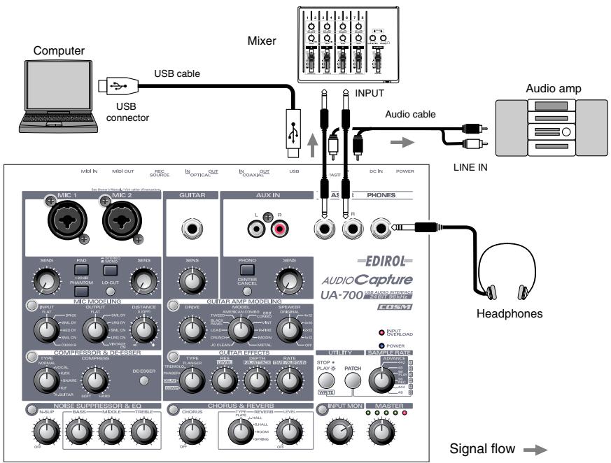
Using the sample rate select switch
- You must set the UA-700's sample rate select switch to match the sampling frequency used by your application.
- If the sample rate select switch is set to 96 kHz REC, you will not hear the sound that is played back by your application.
- If the sample rate select switch is set to 96kHz PLAY, the sound of instruments or audio devices connected to the UA-700 cannot be recorded by your application.
Recording a guitar or bass
With these connections and settings, only the guitar sound will be recorded on your computer when you record into your sequencer application by playing your guitar along with the audio data from your computer.
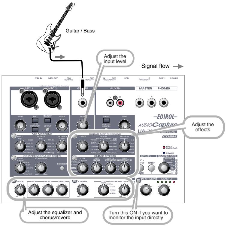
The sound of the device connected to the Guitar input jack will be recorded on both the L channel and R channel on your computer. It will also be output directly from the digital output jack.
Use the Input sensitivity knob to adjust the input level. For the best-quality recording, use the input sensitivity knob to adjust the level until it is as high as you can get it without causing the input peak indicator to light.
Turn on the Input monitor switch, and use the Input monitor knob to adjust the monitor volume of your guitar or bass. This will not affect the recording level.
Do not connect anything to the input jacks that you are not using.
- Guitar effects cannot be applied if you are using 96 kHz PLAY/REC. In this case, only COMPRESSOR & DE-ESSER and NOISE SUPPRESSOR & EQ can be applied.
Recording from mics
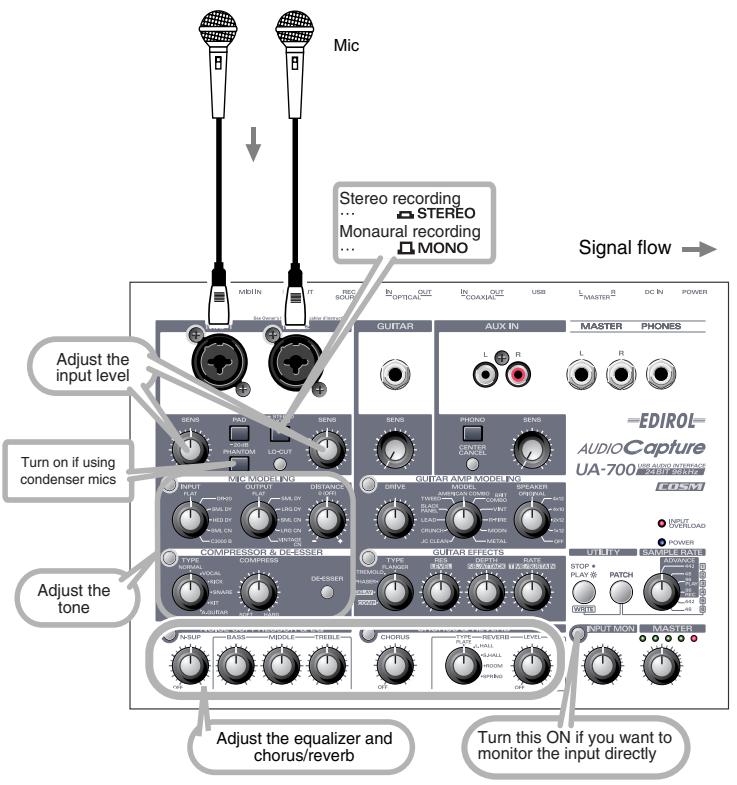
If you are using condenser mics, turn on the Phantom power switch. The sound will also be output directly from the digital output jack.
- If a device that does not use phantom power is connected to the XLR type jacks, you must turn phantom power off, since supplying phantom power to such a device may cause malfunction.
The sound of the device connected to MIC 1 will be recorded on the left channel, and the sound of the device connected to MIC 2 will be recorded on the right channel.
Use the Input sensitivity knobs to adjust the input level. For the best-quality recording, use the input sensitivity knobs to adjust the level until it is as high as you can get it without causing the Input peak indicator to light.
Turn on the Input monitor switch, and use the Input monitor knob to adjust the monitor volume of the mic inputs.
Do not connect anything to the input jacks that you are not using.
- If you are using 96 kHz PLAY/REC, only the COMPRESSOR & DE-ESSER and NOISE SUPPRESSOR & EQ effects can be applied.
-
Howling could be produced depending on the location of microphones relative to speakers. This can be remedied by:
-
Changing the orientation of the microphone(s).
2.Relocating microphone(s) at a greater distance from speakers. - Lowering volume levels.
Recording a keyboard
Here's how your keyboard performance can be sent to the computer as audio data. The audio data can be recorded on your sequencer software.
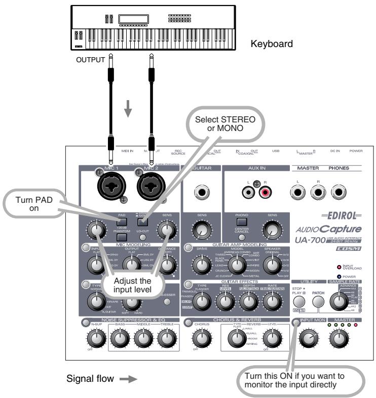
You can use phone plug cables to connect your keyboard (or other device) to the Mic input jacks. If you set the STEREO/MONO select switch to the STEREO position, the sound that is input from MIC 1 will be recorded on the left channel, and the sound from MIC 2 will be recorded on the right channel.
If you set this to the MONO position, the recording will be monaural.
Use the Input sensitivity knobs to adjust the input level. For the best-quality recording, use the input sensitivity knobs to adjust the level until it is as high as you can get it without causing the Input peak indicator to light.
Turn on the Input monitor switch, and use the Input monitor knob to adjust the monitor volume.
Do not connect anything to the input jacks that you are not using.
- Mic effects cannot be applied if you are using 96 kHz PLAY/REC.
Only the COMPRESSOR & DE-ESSER and NOISE SUPPRESSOR & EQ effects can be applied.
Analog recording from an audio device
Make connections as shown in the diagram.
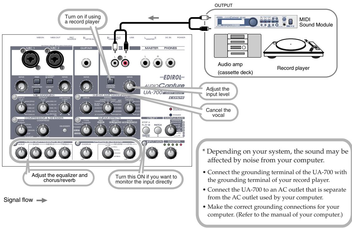
Normally, when connecting a record player, you should turn on the Phono equalizer switch. If your record player includes an equalizer, turn this switch off.
Use the Input sensitivity knobs to adjust the input level. For the best-quality recording, use the input sensitivity knobs to adjust the level until it is as high as you can get it without causing the Input peak indicator to light.
Turn on the Input monitor switch, and use the Input monitor knob to adjust the monitor volume.
Do not connect anything to the input jacks that you are not using.
- If you are using 96 kHz PLAY/REC, you cannot apply the center canceller effect.
Avoid loop connections
UA-700
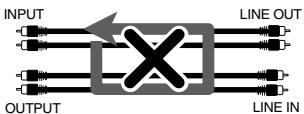
Example of loop connection
Audio amp
(cassette deck, record player)
If the UA-700 is connected as shown in the above diagram to a device that passes the input audio through to the output, and if the Input Monitor switch is turned on, the sound will loop between the UA-700 and that device, producing oscillation at an unexpectedly high volume. Be careful to avoid such connections, since this can cause malfunction or speaker damage.
Input audio from a CD/MD/DAT to your computer
Make connections as shown in the diagram.
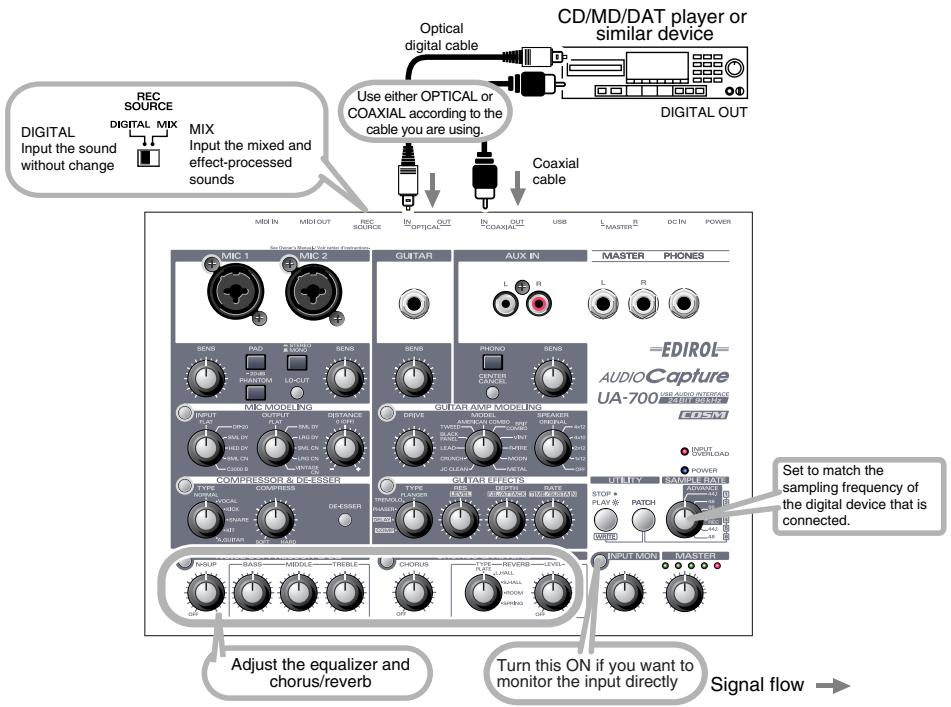
Set the rear panel Record Source select switch to MIX if you want to mix the input from the Mic input jacks or Guitar input jack together with the input signal from the Digital input jack and record the mix. With this setting, you will be able to apply equalizer and chorus/reverb.
Set the rear panel Record Source select switch to DIGITAL if you want to directly input the signal from the digital input jack without processing it. With this setting, the digital signal will be input at its original high quality. You will not be able to apply equalizer or chorus/reverb. Nor will you be able to record guitar or mic along with the digital input.
- The UA-700 does not support the audio formats of professional digital audio devices.
Do not connect anything to the input jacks you are not using.
Built-in sample rate converter
The UA-700 can perform realtime sampling rate conversion of the signal that is input from the digital input jack.
48 kHz -> 44.1 kHz
32kHz - > 48kHz
The digital signal will be converted into the frequency specified by the Sample rate select switch before it is recorded by your application.
Even when recording the digital output of a satellite receiver whose frequency switches automatically, you can obtain high-quality digital recordings without changing the settings of the UA-700 or of your application.
Digitally recording the UA-700's output to an MD
Make connections as shown in the diagram.
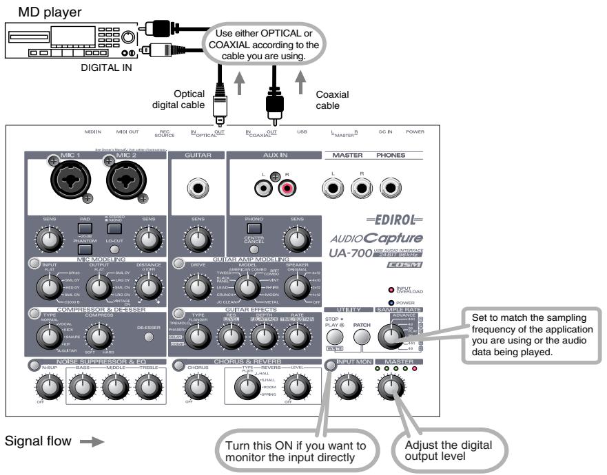
Set the Sample rate select switch of the UA-700 to a sampling frequency that your recording device (e.g., MD) is able to record. Please also note that the application you are using must also be set to the same sampling frequency.
- The UA-700 does not support the audio formats of professional digital audio devices.
The input signals from the various input jacks and digital input jack of the UA-700 can be output directly from the digital output jack.
Do not connect anything to the input jacks you are not using.
Adjusting the audio latency
When using the UA-700 in Advanced mode, you can change the driver settings to adjust the latency of the audio. To adjust the latency, change the Buffer Size in the driver settings dialog box.
-
Latency is the time delay from when an application plays back audio data until the sound is actually heard from an audio device such as the UA-700.
-
As described in Opening the special driver settings dialog box (p. 137), open the "Driver Settings" dialog box.
-
Adjust the driver buffer size.
The following setting will produce the shortest latency.
Windows:
Set "Audio Buffer Size" to the far left (Min).
Macintosh:
Set "Buffer Size" to the far left (Min).
- Click [OK] to close the driver settings dialog box.
- Restart the application that is using the UA-700.
If you are using an application that has a function for testing audio devices, get it to perform its tests.
- Play back audio data on your application.
If interruptions occur in the sound, repeat this procedure, and gradually increase the buffer size specified in step 2 until interruptions no longer occur.
- Depending on the application you are using, there may be a buffer size or latency adjustment function among the audio settings of the application as well. For details, refer to the operation manual for your application.
Using ASIO Direct Monitor
If you are using the UA-700 in Advanced mode from an ASIO 2.0 compatible application, the UA-700's Input Monitor select switch can be controlled from your ASIO 2.0 compatible application.
- As described in Opening the special driver settings dialog box (p. 137), open the "Driver Settings" dialog box.
- Make the following settings.
Check the "Use ASIO Direct Monitor" check box.
-
Click [OK] to close the driver settings dialog box.
-
Depending on your application, there may also be an ASIO Direct Monitor setting among the audio settings of your application. For details, refer to the operation manual for your application.
- When using ASIO Direct Monitor, monitoring may switch on/off at unexpected times, depending on the application settings and on the recording procedure. If this occurs, uncheck the check box in step 2 to disable ASIO Direct Monitor.
Opening the special driver settings dialog box
If using the WDM driver on Windows XP/2000:
- Open the "Control Panel" and double-click "EDIROL UA-700".
-
The "EDIROL UA-700 Driver Settings" dialog box will appear.
-
In Windows XP, click "Switch to classic view" to switch the display to the classic view. EDIROL UA-700 will not be displayed unless the classic view is selected.
If using the MME driver on Windows XP/2000:
- Open the "Control Panel", and double-click "System".
- If you are using Windows XP and cannot find System, click "Switch to classic view" to select the Classic view.
- Click the "Hardware" tab, and click the [Device Manager] button.
- Double-click "Sound, Video, and Game Controllers".
- Double-click "EDIROL UA-700".
- Click the "Properties" tab, and in the "Multimedia Devices" area, double-click "Audio Devices".
- Select "EDIROL UA-700", and click the [Properties] button.
- Click the [Settings] button, and the "EDIROL UA-700 Driver Settings" dialog box will appear.
If using Windows Me/98:
- Open the "Control Panel", and double-click "Sound and Multimedia". (In the case of Windows 98, double-click "Multimedia".)
- Click the "Devices" tab, and double-click "Audio Devices".
- Select "EDIROL UA-700 Audio", and then click the [Properties] button to open Properties.
- Click the [Settings] button, and the "EDIROL UA-700 Driver Settings" dialog box will appear.
If using Macintosh:
Open the ASIO Control Panel from the Audio Settings dialog box of your ASIO-compatible application. The name of the Audio Settings dialog box and the procedure for opening the ASIO Control Panel will differ depending on your application. For details, refer to the operation manual for your application.
Advanced applications
Customizing the effects
You can make additional detailed adjustments to the settings of each effect unit. These parameters are called "Custom parameters".
- Custom parameters can be controlled using the switches of each section and the effect control knobs of the Guitar Effects section.
Guitar Amp Modeling section (p. 139)
| Level | Adjusts the volume. |
| Pre drive | Adds natural and warm distortion. |
| Edge | Adds crispness, and emphasizes the nuances of your picking. |
Compressor/De-esser section (p. 139)
| Level | Adjusts the volume. |
| Attack Time | Adjusts the strength of the attack. Raising this value will sharpen the attacks of the sound, making it crisper. |
| Release Time | Adjusts the time from when the signal falls below the threshold until it returns to its original uncompressed state. |
Chorus/Reverb section (p. 140)
| Chorus/Pre-Delay | Adjusts the time from when the direct sound is output until the effect sound is output. Lengthening the pre-delay will create a sensation of multiple sounds being played together (a doubling effect). |
| Chorus Depth | Adjusts the depth of the chorus effect. Set this to “0” if you are using this as a doubling effect. |
| Chorus Rate | Adjusts the speed of the chorus effect. |
■Guitar Amp Modeling section
Procedure
- Turn the Model knob to select the guitar amp that you want to adjust.
- Press and hold the Guitar Amp Modeling switch for at least three seconds.
The Guitar Amp Modeling switch and the Guitar Effects switch will blink, and the UA-700 will enter a mode that lets you adjust the Guitar Amp Modeling custom parameters.
- With the indicators of the Guitar Amp Modeling switch and Guitar Effects switch both blinking, turn the Guitar Effects section Effect control knobs 1-3 (p. 121) to adjust each custom parameter.
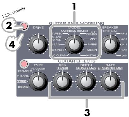
| Effect control knob 1 | Level |
| Effect control knob 2 | Pre-drive |
| Effect control knob 3 | Edge |
- Press the Guitar Amp Modeling switch once again to make it light.
The Guitar Effect Switch will stop blinking, and you will exit the custom parameter adjustment mode.
- The custom parameters you adjusted will return to the factory settings when the power is turned off.
- You can make independent settings for each of the eleven different guitar amp models.
Compressor/De-esser section
Procedure
- Turn the
Compressor type select knob to select the compressor type that you want to adjust.
- Press and hold the
Compressor/Deesser switch for at least three seconds.
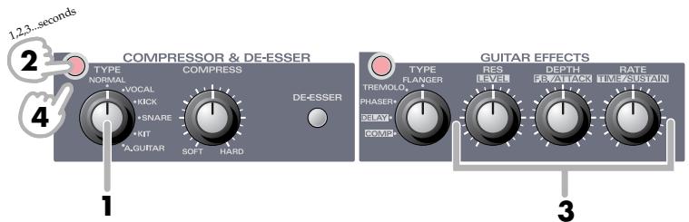
The Compressor/De-esser switch and the Guitar Effects switch will blink, and the UA-700 will enter a mode that lets you adjust the Compressor's custom parameters.
- With the indicators of the Compressor/De-esser switch and Guitar Effects switch both blinking, turn the Guitar Effects section Effect control knobs 1-3 (p. 121) to adjust each custom parameter.
| Effect control knob 1 | Level |
| Effect control knob 2 | Attack time |
| Effect control knob 3 | Release time |
- Press the Compressor/De-Esser switch once again to make it light.
The Guitar Effect Switch will stop blinking, and you will exit the custom parameter adjustment mode.
- The custom parameters you adjusted will return to the factory settings when the power is turned off.
- You can make independent settings for each of the six different compressor types.
Chorus/Reverb section
Procedure
- Press and hold the Chorus/Reverb switch for at least three seconds.
The Chorus/Reverb switch and the Guitar Effects switch will blink, and the UA-700 will enter a mode that lets you adjust the Chorus/Reverb custom parameters.
- With the indicators of the Chorus/Reverb switch and Guitar Effects switch both blinking, turn the Guitar Effects section Effect control knobs 1-3 (p. 121) to adjust each custom parameter.
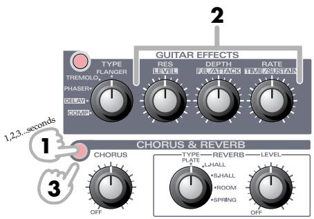
| Effect control knob 1 | Chorus pre-delay |
| Effect control knob 2 | Chorus depth |
| Effect control knob 3 | Chorus rate |
- Press the Chorus/Reverb switch once again to make it light.
The Guitar Effect Switch will stop blinking, and you will exit the Custom parameter adjustment mode.
- The custom parameters you adjusted will return to the factory settings when the power is turned off.
Adjusting the volume of the effects
In some cases, the sound may become distorted during recording or playback when delay, reverb, or other effect sound is added. If this occurs, use the following procedure to adjust the level appropriately.
Procedure
- Press and hold the Input Monitor switch for at least three seconds.
The Input Monitor switch and Guitar Effects switch will blink, and the UA-700 will enter a mode that lets you adjust the Effect output level.
- While listening to the sound, turn Effect control knob 1 (p. 121) until the sound is no longer distorted.
During recording, adjust this so that the Input level indicator of your sequencer software does not reach the maximum.
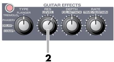
If effect control knob 1 is set to the

position, the
volume will be at unity gain.
[Bypassed ... input:output are in a 1:1 ratio (0 dB)]
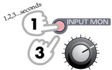
- If you leave the Input Monitor knob and the Master Volume knob at the

position (0 dB), the
recorded volume will be the same as the output volume. This is convenient when adjusting the effect volume.
-
When you press the Input Monitor switch, it will stop blinking, and you will exit the Effect output level adjustment mode.
-
The setting you adjusted will return to the factory setting when the power is turned off. (0 dB = input:output ratio of 1:1)
- The setting you adjusted can be stored in a patch.
Block diagram
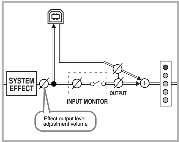
Switching patches from an external device
Switching patches from a sequencer
Here's how the six patches stored in the UA-700 can be selected from your sequencer software.
- Select [EDIROL UA-700 CONTROL] as the output destination for a MIDI track in your sequencer software that contains MIDI data for switching patches.
- When you transmit a program change (PC) message from your sequencer, the UA-700 will switch patches.
Program changes and UA-700 patches correspond as follows.
PC #0 patch 1
PC #1 patch 2
PC #2 patch 3
PC #3 patch 4
PC #4 patch 5
PC #5 patch 6
- Program changes are received on all channels.
Switching patches from an external MIDI device
Even if the UA-700 is not connected via USB, you can use a MIDI foot controller such as the Roland GFC-50 to switch UA-700 patches.
- Connect your MIDI foot controller to the UA-700's MIDI IN connector.
- When you transmit a program change (PC) message from your foot controller, the UA-700 patch will change.
PC #0 patch 1
PC #1 patch 2
PC #2 patch 3
PC #3 patch 4
PC #4 patch 5
PC #5 patch 6
Sequencer control switch settings
You can use the UA-700's sequencer control switch to start/stop playback or recording on your sequencer.
Settings for SONAR 1.0
- From the Options menu, choose MIDI Devices.
In the MIDI Devices dialog box, select [EDIROL UA-700 CONTROL] as both the Inputs and Outputs.
- From the Options menu, choose Key Bindings.
Make the following settings in the Key Bindings dialog box.
[Type of Keys]
Check "MIDI" and "Enable"
[MIDI 'Shift' Options]
Check "Key", and input "C 0"
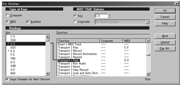
Stopping the sequencer
- In the [Boundings] area, set [Key] to [D 0].
- In the [Function] area, select [Transport | Stop].
- Click the [Bind] button.
The [Key] [D 0] will be connected to the [Function] area [Transport | Stop].
If you also want to assign the UA-700's PLAY button (Sequencer Control switch) to start recording on your sequencer, proceed to step 6. If you want to assign the PLAY button (Sequencer Control switch) to start playback on your sequencer, proceed to step 10. If you have now finished making settings, click the [OK] button. The Shortcut Key dialog box will close, and the settings will be completed.
Starting recording
- In the [Boundings] area, set [Key] to [D 0].
- In the [Function] area, select [Transport | Record].
- Click the [Bind] button.
The [Key] [D 0] will be connected to the [Function] area [Transport | Record].
- Click [OK] to close the Key Bindings dialog box and complete the setting.
Starting playback
- In the [Boundings] area, set [Key] to [E 0].
- In the [Function] area, select [Transport | Play].
- Click the [Bind] button.
The [Key] [E 0] will be connected to the [Function] area [Transport | Play].
- Click [OK] to close the Key Bindings dialog box and complete the setting.
If you are using another sequencer
If you press the Sequencer control switch when the button is dark, the following messages will be transmitted from the UA-700 to the MIDI port [EDIROL UA-700 CONTROL] of your computer.
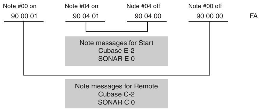
If you press the Sequencer Control switch when the button is lit, the following messages will be transmitted from the UA-700 to the MIDI port [EDIROL UA-700 CONTROL] of your computer.
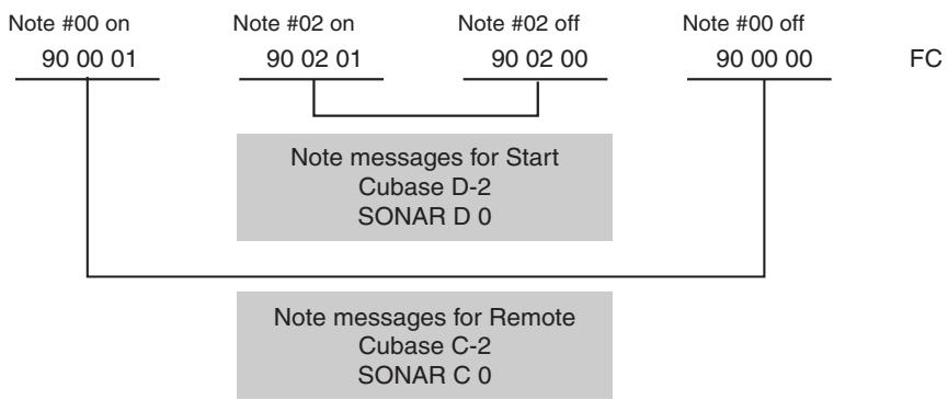
Send/Return mode
The UA-700 provides a mode that lets you apply effects to the audio data played back by your computer, and then re-record it on your computer. (See the block diagram.)
Use this when you want to apply effects to existing audio data.
- Turn on the power while holding down the Input Monitor switch.
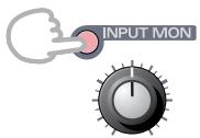
To cancel Send/Return mode, turn on the power once again without holding down the Input Monitor switch.
- External input from a guitar or mic is not possible in this mode.
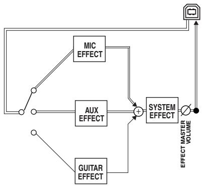
Restoring the factory settings
- Turn on the power while holding down the Patch Mode switch and Sequencer Control switch.
- All of the panel buttons will blink several times.
The factory settings have been restored.
- Patch data will return to the factory settings.
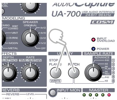
Limitations at 96 kHz
- Only the Noise Suppressor & Equalizer section and the Compressor & De-Esser section will function at 96kHz .
- You cannot record and play back simultaneously.
Block diagram
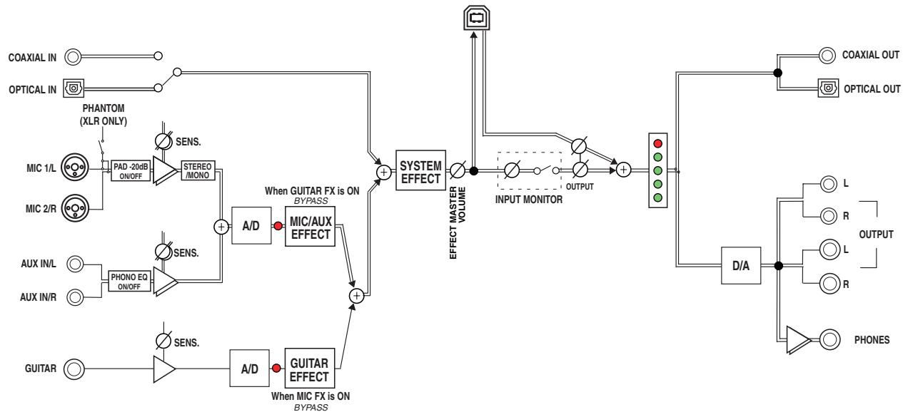

Example of loop connection

Audio amp
(cassette deck, record player)
Section entree micro
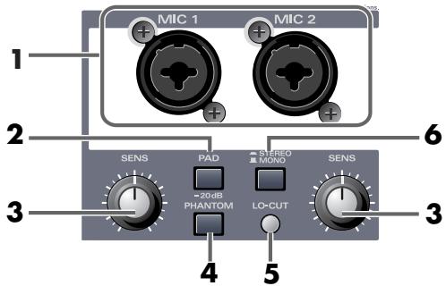
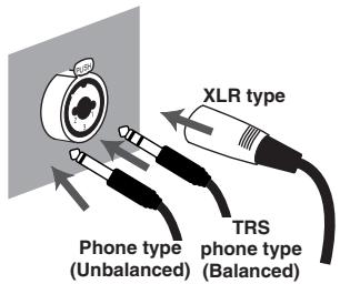
Section MIC MODELING
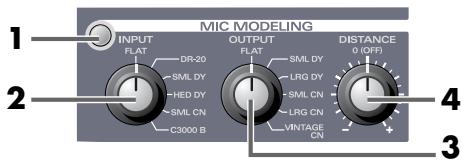
Section Compressor & De-esser
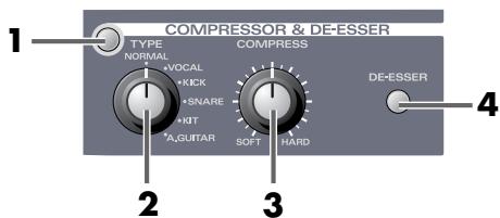
Section Guitar Amp Modeling
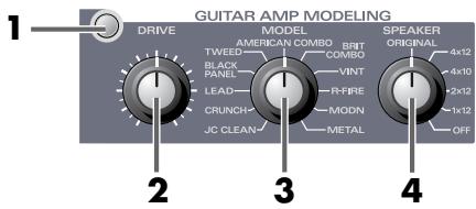
Section Noise Suppressor & EQ
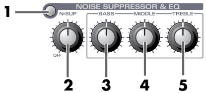
Section Chorus/Reverb
Chorus
1. Commutateur Chorus/Reverb

Example of loop connection
Audio amp
(cassette deck, record player)
Section Guitar Amp Modeling (p. 205)
Section Compressor/De-esser (p. 205)
Section Chorus/Reverb (p. 206)
Section Guitar Amp Modeling
Procedure
Section Compressor/De-esser
Procedure
Section Chorus/Reverb
Procedure
1. Interruftore Guitar Amp Modeling
4. Manopola speaker cabinet (SPEAKER)
1. Interruftore Guitar Effects
Selectionare Flanger, Tremolo, Phaser, Delay o Compressor.
1. Interru tture Chorus/Reverb
Modo ADVANCE DISATTIVATO (modo driver standard)
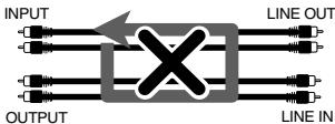
Example of loop connection

Audio amp
(cassette deck, record player)
If an unexpected problem occurs while using the SD-80, read this chapter first. It contains numerous tips for resolving problems.
If you are using Windows or Macintosh for the first time, and as a result find it difficult to follow the procedural explanations, please refer to the manuals that came with your computer or operating system.
Problems related to the USB driver 241
An "Unknown driver found" dialog box appears, and you are unable to install the driver 241
"Find new hardware wizard" does not execute automatically 241
"Find new hardware wizard" ends before the process is completed 241
"Found unknown device" appears even though you installed the driver 242
Driver is not installed correctly 242
Can't install/delete/use the driver in Windows XP/2000 242
Windows XP/2000 displays a "Hardware Installation" or "Digital Signature Not Found" dialog box 242
Device Manager shows "?","!”, or "USB Composite Device" 242
The "Insert Disk" dialog box does not appear 242
A dialog box says "Can't use driver required by USB device 'EDIROL UA-700'" ....243
Problems when using the UA-700 243
Operating system becomes unstable 243
Can't hear sound from the computer 243
Can't play back / record MIDI 245
Interrupted notes or delays occur during MIDI playback 245
Sound from devices connected to the input jack is not heard in the headphones.....246
Volume from a device connected to the input jacks is too low. 246
The sound of a device connected to the input jack is distorted 246
Noise is heard during audio playback 246
Sound is interrupted during audio playback 247
Digitally recorded sound is distorted, is at the wrong pitch, or contains noise. 249
Playback or recording halts midway through, and then becomes impossible........250
Recording produces a silent (blank) file 250
Game background music does not play 250
Effects are not applied. 250
Sound becomes distorted or noisy when you apply an effect 250
Recorded sound is too soft 250
Noise is heard when you connect a record player. 251
A loud buzz is present in the guitar signal 251
Deleting the special driver 251
Windows XP/2000 users 251
Windows Me/98 users. 252
Macintosh users 253

Problems common to Windows and Macintosh

Problems occurring only in Windows

Problems occurring only in Macintosh
Problems related to the USB driver

An “Unknown driver found” dialog box appears, and you are unable to install the driver

"Find new hardware wizard" does not execute automatically

"Find new hardware wizard" ends before the process is completed
- It may take about 15 seconds (or more) after the USB cable is connected for the UA-700 to be detected.
- Is the USB cable connected correctly?
Make sure that the UA-700 and your computer are correctly connected via a USB cable.
- Is USB enabled on your computer?
Refer to the operation manual for your computer, and make sure that USB is enabled.
It has been found that in some cases, not all of the Windows 98 files required to support audio via USB are installed when a computer is shipped.
Please contact the manufacturer of your computer.
- Does your computer meet the USB specifications?
If you are using a computer that does not fulfill the electrical requirements of the USB specifications, operation may be unstable. In this case, you may be able to solve the problem by connecting a USB hub.
- Does "Unknown device" appear for "Other device" or "Universal serial bus controller"?
Use the following procedure to delete "Other device" (Universal Serial Bus Controller) "Unknown device", and then restart your computer.
- In the Windows Control Panel, double-click System. The System Properties dialog box will appear.
- Click the Device Manager tab.
- Double-click "Other device" or "Universal Serial Bus Controller" to display a list of devices.
- From the list, select the unknown device and click [Delete].
- In the dialog box that asks you to confirm the deletion, click [OK].
- Verify that "Other device" or "Unknown device" is not displayed in the list, and click [Close] to close the dialog box.

"Found unknown device" appears even though you installed the driver
If your computer or USB hub has two or more USB connectors, and you connect the UA-700 to a USB connector to which the UA-700 has never been connected before, the “Unknown device” dialog box may appear even on a computer onto which you have already installed the driver.
Refer to Getting Connected and Installing Drivers (Windows) (p. 14), and install the driver once again. This is not a malfunction.

Driver is not installed correctly
As described in Deleting the special driver (p. 251), delete the USB audio device driver that is installed in your computer, and then install the UA-700 driver once again as described in Getting Connected and Installing Drivers (Windows) (p. 14). Also check whether there is an “Unknown device” in “Other devices” or “Universal Serial Bus Controller.”
If you find one, delete it.

Can't install/delete/use the driver in Windows XP/2000
- Did you log on to Windows as a user with administrative privileges?
In order to install/delete/re-install the driver in Windows XP/2000, you must be logged into Windows as a user with administrative privileges, such as Administrator. For details, please contact the system administrator for your computer system.
- Did you make "Driver Signing Options"?
In order to install/re-install the driver, you must make "Driver Signing Options".
(Windows XP p. 16, Windows 2000 p. 22)

Windows XP/2000 displays a "Hardware Installation" or "Digital Signature Not Found" dialog box
- Did you make "Driver Signing Options"?
In order to install/re-install the driver, you must make the settings described in "Driver Signing Options". (Windows XP p. 16, Windows 2000 p. 22)

Device Manager shows “?”, “!”, or “USB Composite Device”

The "Insert Disk" dialog box does not appear
Use the following procedure to re-install the driver.
- Turn off the power of your computer, and start up Windows with all USB cables disconnected (except for keyboard and mouse).
- After Windows restarts, use a USB cable to connect the UA-700 to your computer.
-
Click the Windows [Start] button, and from the menu that appears, choose Settings | Control Panel.
-
Double-click the System icon. The System Properties dialog box will appear.
- Click the Device Manager tab.
- Check whether you can see an indication of “?Composite USB Device”, “?USB Device”, “!USB Device”, or “USB composite device” displayed below “Sound, Video, and Game Controllers”, “Other Devices”, or “Universal Serial Bus Controller”. If you find any such indication, select it and click [Delete].
- A dialog box will ask you to confirm deletion of the device. Verify the contents of the dialog box, and then click [OK]. In the same way, delete all indications of “?Composite USB Device”, “?USB Device”, “USB Device”, and “USB composite device” that you find.
- If you find EDIROL UA-700 with a yellow “!” or a red “?” displayed beside it, delete this in the same way.
- When you have finished deleting the unwanted devices, click [OK] in the System Properties dialog box.
- Turn off the power of the UA-700, then delete the driver. ( Deleting the special driver (p. 251))
-
Restart Windows. Then install the driver once again. ( Getting Connected and Installing Drivers (Windows) (p. 14)).
-
If the problem still occurs after you have taken the above measures, please refer also to the Readme file for the USB driver. The Readme file is on the CD-ROM.

A dialog box says "Can't use driver required by USB device 'EDIROL UA-700'
- [Special driver mode] Are you using only audio?
You must install the MIDI driver even if you are using the UA-700 only with audio. Please install the UA-700 driver for OMS or FreeMIDI.
(→Installing the special driver (p. 40))
Problems when using the UA-700

Operating system becomes unstable
- Operation becomes unstable when the computer is started up with the UA-700 already connected. Please start up your computer with the UA-700 disconnected, and then connect the UA-700. On a computer that uses a USB keyboard, starting up the computer with the UA-700 already connected may cause operation to become unstable. In this case, start up the computer with the UA-700 disconnected, and then connect the UA-700.

Can't hear sound from the computer
Is the Sampling frequency select switch set to "96 kHz REC"?
If the sampling frequency is 96kHz , the Sampling frequency select switch must be set differently, depending on whether you are recording or playing back. When playing back at 96kHz , set the front panel Sampling frequency select switch to 96kHz PLAY.
In order for the setting to take effect, you must exit all applications, switch off the UA-700, then turn it back on again. (1. Sample rate select switch (p. 125))
- Is it possible that the UA-700's Master volume has been placed at 0 (turned fully counterclockwise)?
- The UA-700's Sampling frequency select switch may have been set to "96 kHz REC". With this setting, only recording is possible. Sound from the computer cannot be played back.
- Have you specified the audio and MIDI data output destination for your operating system? You must specify the UA-700 as the audio data output destination for your computer. For details on how to make this setting, refer to Settings and checking. (Windows, Settings and checking (p. 33)/ Macintosh, OMS settings (p. 41), FreeMIDI settings (p. 45))
- In your playback software, have you specified the audio data output destination? For some software, such as Cool Edit Pro LE, you will need to specify the UA-700 as the output destination for audio data. For details on the procedure for making settings, refer to the owner's manual for your software.
- Are you running multiple applications?
- If multiple applications are running simultaneously, an error message may appear. If this occurs, click [OK] and exit the other applications.
- Even if an application window is closed, it is still running if it appears in the taskbar. Be sure to exit unneeded applications displayed.
- Was the driver installed correctly? In order for you to play back audio data via the UA-700, the driver must be installed. For installation and settings, refer to "Getting Connected and Installing Drivers" (Windows, p. 14 / Macintosh, p. 39).
- Is your computer in Suspend or Sleep mode? If so, get your computer to resume normal operation, then exit all applications that are using the UA-700. Next, turn the UA-700's power off, then switch it on again.
- Did you plug in the USB cable, or unplug it while an application was running?
- Exit all applications that are using the UA-700, and exit all applications that are using the UA-700, and re-connect the UA-700.
- Have you selected "Game compatible device" or "Voice modem" as the output for the audio track? If game compatible device or voice modem (the actual name will depend on the computer you are using) is selected for the audio track of your software, the audio track may not play back. Do not select these devices as the port.
- Has your computer been set to enter Sleep mode? If your computer enters Sleep mode, exit the software you are using, and then restart your computer. We recommend that you set your computer to not use Sleep mode.
Windows
- [Standard driver mode] Are you attempting to play back an audio CD using your computer's CD player? If you want to play an audio CD from your computer's internal CD-ROM drive, refer to When playing audio CDs from the computer's internal CD-ROM drive, or using the UA-700 to play game music (Standard driver mode only) (p. 37)
- [Standard driver mode / Windows XP/2000 WDM driver] Are the volume control faders raised? Adjust the volume of the faders as described in Volume Control setting (p. 36).
Can't play back / record MIDI

- Has the MIDI device you are using been set correctly?
In order to record/play MIDI tracks using the UA-700, you must correctly install the UA-700 driver (Getting Connected and Installing Drivers (Windows) (p. 14)).
Also make sure that the input port and output port are set as follows in your software.
| INPUT port | OUTPUT port |
| EDIROL UA-700 MIDI IN | EDIROL UA-700 MIDI OUT |

- Has the MIDI device you are using been selected correctly?
Select [UA-700 MIDI IN/OUT] as the MIDI output device.

- Are the track outputs set correctly?
MIDI tracks to which no MIDI playback device is assigned will not be heard. If you want to play back a MIDI track, you must make sure that the MIDI device you want to use is displayed in your software as the MIDI output port. For details, refer to the owner's manual for your software.

- Is OMS/FreeMIDI set correctly?
As described in OMS settings (p. 41) or FreeMIDI settings (p. 45), check the OMS or FreeMIDI settings. Also make sure that the device for MIDI IN/OUT is correctly selected in the MIDI settings of your MIDI sequencer software.

Is the OMS setup enabled?
If a diamond-shaped symbol is not displayed at the left edge of the title area in the OMS setup window, the setup is not enabled. From the OMS File menu, choose "Make Current". (OMS settings (p. 41))
Interrupted notes or delays occur during MIDI playback

-
Make Windows XP settings to enable background processing.
Make the following settings so that MIDI processing will occur smoothly. -
Click the Windows start button, and from the menu that appears, select Control Panel.
- In "Pick a category", click "Performance and Maintenance".
-
In "or pick a Control Panel icon", click the System icon.
-
Click the Advanced tab.
- At the right of the Performance field, click [Settings]. The Performance Options dialog box will appear.
- Click the Advanced tab.
- In the Processor Scheduling field, select "Background services", and click [OK].
- In the System Properties dialog box, click [OK]. The System Properties dialog box will close.
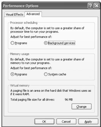

Sound from devices connected to the input jack is not heard in the headphones
- Is the headphone volume set appropriately?
Turn the knob clockwise to adjust the volume.
Is the input monitor switch turned on (lit)?
Turn it on (lit).
- Is the recording source select switch set to MIX?
Set it to MIX.

Volume from a device connected to the input jacks is too low
- Are you using a cable that has a built-in resistor?
Use a cable without a built-in resistor (e.g., Roland PCS series).
Is the Input volume raised appropriately?
Turn the knob clockwise to adjust the volume.

The sound of a device connected to the input jack is distorted
If you are inputting sound through the input jacks, use the Input sensitivity knobs of the UA-700 to lower the input level.

Noise is heard during audio playback
Is a mic or guitar still connected?
If a mic or guitar is connected to the UA-700, disconnect the mic or guitar, and turn the input sensitivity knob all the way to the left. Disconnect any audio devices you are not using.
- Noise is sometimes heard in the line input or mic input.
If a USB-compatible MIDI sound module and the UA-700 are connected via USB to the same computer, and the outputs of the MIDI sound module are connected to the line input jacks of the UA-700, noise from your computer may be heard via the MIDI sound module from the UA-700, depending on the computer you are using. If this occurs, you can either connect the MIDI sound module and the UA-700 in parallel using a self-powered hub, or connect the MIDI sound module via its serial or MIDI interface.
- Are two or more audio devices such as the UA-700 or a mixer connected to your computer?
Try connecting only a single UA-700 unit, and check whether the noise disappears. If numerous audio devices are connected to a computer, noise may occur depending on your system. In such cases, connect only the UA-700 to your computer.

- Does your sequencer software support ASIO 2.0?
If your ASIO-compatible software does not support ASIO 2.0, it will not operate correctly if you use [UA-700 ASIO2.0 16bit] or [UA-700 ASIO2.0 24bit] as the ASIO driver.
In this case, select either [UA-700 ASIO1.0 16bit] or [UA-700 ASIO1.0 24bit] as the ASIO driver.

- Does your sequencer software support 24-bit audio?
If your ASIO-compatible software does not support 24-bit audio input/output, it will not operate correctly if you select [UA-700 ASIO1.0 24bit] or [UA-700 ASIO2.0 24bit] as the ASIO driver. In this case, select either [UA-700 ASIO1.0 16bit] or [UA-700 ASIO2.0 16bit] as the ASIO driver.

Is the UA-700 connected to a USB hub?
Try connecting the UA-700 directly to the USB connector of the Macintosh itself.

- Are you using a USB device other than the UA-700?
Try turning off the power of all USB audio devices other than the UA-700.

-
In some cases, you may also be able to solve this problem by grounding the chassis of your computer, or the grounding connector of the AC power supply plug of your computer. In addition, you can check whether any devices that produce a strong magnetic field are located nearby, such as a television or microwave oven.
-
Also check the troubleshooting item Sound is interrupted during audio playback (p. 247)
Sound is interrupted during audio playback

- Are many applications running on your computer?
If you use many applications or start up other applications during playback, playback may be interrupted, depending on your computer system. Please exit unneeded applications, and try again. If this does not resolve the problem, try restarting your computer.

- Graphic accelerators may cause noise to be heard during audio playback.
Use the following procedure to turn the graphic accelerator "Off".
- In the Windows Control Panel, double-click Display to open the Display Properties dialog box, and click the Settings tab.
- Click Advanced, and in the properties that appear, click the Performance tab. For Windows XP, click Advanced, and then click the Troubleshoot tab.
For Windows 2000, click Advanced, and then click the Troubleshooting tab.
- Set the Hardware acceleration slider to None, and click [OK].
- In the Display Properties dialog box, click [OK] to close the dialog box. Then restart your computer.

- In Windows XP, make the settings that enable background processing.
Make these settings so that audio processing can be performed smoothly.
Make settings as described in Make Windows XP settings to enable background processing. (p. 245).

- Try using the following procedure to change your disk drive settings.
The following setting item may not exist on some computers.
- In the Windows Control Panel, double-click System.
- Click the Device Manager tab.
- Double-click Disk Drives to see the list of devices.
-
From the list, select GENERIC IDE DISK TYPE??, and click Properties to access the GENERIC IDE DISK TYPE?? Properties dialog box.
-
In the ?? field of GENERIC IDE DISK TYPE??, there will be a number that differs depending on your computing environment.
-
Click the Settings tab, place a check mark in the check box for the DMA option, and click [OK] to close the dialog box.
-
Depending on your system, a DMA Settings dialog box may appear. Check the contents, and click either [OK] or [Cancel].
-
In the System Properties dialog box, click [OK] to close the dialog box. Then restart your computer.

Try installing more memory.
Installing more memory will increase the performance of your computer. For details on how to install more memory, refer to the operation manual for your computer.

- Does your computer satisfy the requirements of the USB standard?
If you are using a computer (such as a computer that you yourself assembled) that does not satisfy the electrical requirements of the USB specifications, you may experience interruptions in the audio. If this occurs, you may be able to solve the problem by connecting a USB hub that contains its own power supply.

- On some computers, audio playback may be interrupted due to the Power Management settings in the Control Panel.
The Power Supply Properties that you see when you double-click Power Management will differ depending on your computer system. One example is given below, but you should also refer to the operation manual for your computer. Some computers may not have all of the following setting items.
-
Click the Windows Start button, and select Settings | Control Panel to open the Control Panel.
-
In Control Panel, double-click System to open the System Properties dialog box.
- Click the Device Manager tab.
- Double-click System Devices to display the list of devices.
- From the list, select Advanced Power Management Support. Then click Properties to open the Advanced Power Management Support Properties dialog box.
- Click the Settings tab, and in Troubleshooting, place a check in the check box for Don't Poll Power Supply Status. Then click [OK].
- In the System Properties dialog box, click [OK].
- Restart Windows.
Windows
- If you are using the special driver, you can solve this problem in the "EDIROL UA-700 Driver Settings" dialog box.
For details, refer to the section "Something is wrong with playback; sound is interrupted or notes are missing" within the Readme_e file located in the folder in which you installed the CD-ROM.
Windows
Depending on the virtual memory setting or network-related settings, noise may occur. Please make the following settings before use.
- In Chooser of the Apple menu, set AppleTalk to "Inactive".
(This setting is not changed as a result of turning off AppleTalk, as requested by OMS when sequencer software is started up. You must change the setting yourself using the "Chooser".) - In the "Memory" Control Panel, set Virtual Memory to "Off".
- Depending on the way in which you connect to the Internet, use the UA-700 with the following settings.
If you connect to the Internet via a LAN cable
Use while the LAN cable is connected.
If you connect to the Internet via the internal modem port, or are not connected to the Internet In the "TCP/IP" Control Panel, set "Connect via" to "PPP".
After you have made the settings, restart your Macintosh.
- Do not use software that accesses the network (such as a Web browser) at the same time that you are using sequencer software or audio editing software.
Macintosh
- Try increasing the Buffer Size in the ASIO Driver control panel.
The name of the settings dialog box will differ depending on your software.
- If you change the buffer size, you must exit the software and then restart it.
- Roland can make no guarantee of, nor provide support regarding the operation of sequencer software and audio editing software made by another manufacturer. Please contact the manufacturer of the software you are using.
Macintosh
* Digitally recorded sound is distorted, is at the wrong pitch, or contains noise
-
If you are using a long optical digital cable, noise may be produced when the cable is connected, or the sound may be distorted. We recommend that you use optical digital cables that are no longer than one meter in length.
-
Does the sampling frequency setting of your application match the setting of the UA-700's sampling frequency switch?

Playback or recording halts midway through, and then becomes impossible
- Was a heavy processing load experienced while using the UA-700, such as accessing the CD-ROM drive or a network?
If an operation involving a heavy processing load is performed while the UA-700 is in use, it may not operate correctly. If this occurs, stop playback/recording, and then try resuming playback/recording. If you are still unable to play back/record, exit all applications that use the UA-700, switch off the UA-700, then turn it on again.

Recording produces a silent (blank) file
- Try setting the bit rate to "16 bit or higher".
If you are using Windows 98 Second Edition and your recording software is set to a bit rate setting of 8 bits, a silent file may be created, effectively making recording impossible. If this occurs, set the bit rate to "16 bit or higher", and you will be able to record normally.
- Is the Recording source select switch set correctly?
- In your operating system, is the audio data input destination set correctly?
- On your recording software, is the audio data input destination set correctly?
- The UA-700's Sampling frequency select switch may have been set to "96 kHz PLAY". When set to "96 kHz PLAY", only playback is possible. If you want to record the sound from your computer, choose a setting other than "96 kHz PLAY".

Game background music does not play
- Does the game use an audio CD for background music? (Standard driver mode)
If the game uses an audio CD for background music, refer to When playing audio CDs from the computer's internal CD-ROM drive, or using the UA-700 to play game music (Standard driver mode only) (p. 37).

Effects are not applied
- Are you using the UA-700 at 96kHz ?
If you are using the UA-700 at 96 kHz, you cannot apply effects other than COMPRESSOR & DE-ESSER and NOISE SUPPRESSOR & EQ.

Sound becomes distorted or noisy when you apply an effect
Adjust the volume of the effect unit. (-> "Adjusting the volume of the effect unit" (p. 82))

Recorded sound is too soft
Adjust the volume of the effect unit. (-> "Adjusting the volume of the effect unit" (p. 82))

Noise is heard when you connect a record player
- Have you connected the grounding terminal?
Depending on your system, the UA-700 may be affected by noise from your computer. Please ground the grounding terminals of the UA-700 and your computer.
Sometimes this problem can be solved by grounding the chassis of your computer, or the grounding connector of your computer's AC power supply. You should also check whether there is a device nearby that produces a strong magnetic field, such as a television or a microwave oven. (p. 68)

A loud buzz is present in the guitar signal
- Does the buzz decrease when you lower the volume of your guitar?
If the buzz decreases when you lower the volume of your guitar, it is possible that the pickup of your guitar is receiving noise from a computer or a display screen. Move as far away from the computer as possible.
Sometimes this problem can be solved by grounding the chassis of your computer, or the grounding connector of your computer's AC power supply. You should also check whether there is a device nearby that produces a strong magnetic field, such as a television or a microwave oven. (p. 68)
Deleting the special driver
If you were unable to install the special driver according to the procedure given, the UA-700 may not be recognized correctly by the computer. In this case, use the following procedure to delete the special driver, and then follow the procedure in Getting Connected and Installing Drivers (Windows, p. 14; Macintosh, p. 39) to install the driver once again.
Windows XP/2000 users
In order to delete (uninstall) the driver, a user with administrative privileges such as Administrator must be logged onto Windows. For details, contact the system administrator of your computer.
- With all USB cables disconnected, start Windows. (USB keyboard and USB mouse excepted)
-
Log on to Windows under a user name belonging to the Administrator group, such as "Administrator".
-
Set the UA-700's ADVANCE (mode select) switch to the ON position.
- After connecting the UA-700 to your computer via a USB cable, turn on the power of the UA-700.
- Exit all applications before deleting the driver.
-
Open the Control Panel, and double-click System.
-
In Windows XP, click “Switch to classic view” to switch the display to the classic view. EDIROL UA-700 will not be displayed unless the classic view is selected.
-
Click the Hardware tab, and in the "Device Manager" area, click [Device Manager].
-
Double-click "Sound, Video, and Game Controllers" to view the list of devices.
-
From the list, click "EDIROL UA-700 (WDM)" or "EDIROL UA-700 (MMX)" to select it. Then right-click, and from the menu that appears, select "Delete".
- If “EDIROL UA-700 (WDM)” or “EDIROL UA-700 (MMX)” does not appear in the list, refer to the “Can’t install/delete/use the driver in Windows XP/2000” section (p. 242) in “Troubleshooting”.
- A dialog box will ask you to confirm that you want to delete the device. Verify the contents of the dialog box, and click [OK].
- Close the Device Manager window, and click [OK] in System Properties.
- Disconnect the USB cable from the UA-700.
- Restart Windows.
Windows Me/98 users
- With all USB cables disconnected, start up Windows. (USB keyboard and USB mouse excepted)
- Set the UA-700's ADVANCE (mode select) switch to the ON position.
- After connecting the UA-700 to your computer via a USB cable, turn on the power of the UA-700.
- Exit all applications before deleting the driver.
-
Open the Control Panel, and double-click System.
-
Depending on the state of your computer, System may not appear in the Control Panel. In this case, click "Show all control panel options".
-
Click the Device Manager tab.
- Double-click "Sound, video, and game controllers" to see a list of devices.
- From the list, click "EDIROL UA-700" to select it, and click [Remove].
- A dialog box will appear, asking you to confirm that you want to delete the driver. Verify the contents, and click [OK].
- Click [Close] to close System Properties.
- Disconnect the USB cable from the UA-700.
- In Control Panel, click Folder Options and then click the Display tab. (In Windows 98, click Start Settings Folder Options)
- In Advanced settings of the View tab, remove the check mark for "Hide protected operating system files (Recommended)", click "Show hidden files and folders", and then click [OK]. (In Windows 98, this will be "Show all files".)
- Click Start Find Files or folders.
- In "Search location", select "Local hard drive". Then in "Name of file or folder", type "0024.*" and click [Begin search].
-
Of the files that are found, delete the five files Rdas0024.DLL, Rddp0024.dat, Rddv0024.drv, Rdvx0024.vxd, and Rdwm0024.sys. If the list shows Rdif0024.inf or RolandRDIF0024.INF, delete these files as well.
-
Never delete any file other than the files specified here.
-
Restart Windows.
Macintosh users
- Disconnect the USB cable (by which the UA-700 is connected) from your Macintosh.
- From the system extensions folder, drag "USB UA-700 Driver" into the trash to delete it.
- Delete UA-700 from the OMS Folder inside the System folder, or drag UA-700 Driver from the FreeMIDI Folder to the trash.
- Drag the ASIO driver that you installed in Installing the ASIO driver (p. 47) into the trash to delete it.
- Restart the Macintosh.
MIDI implementation
The operation of the UA-700 can be controlled by MIDI messages. The following MIDI messages are used for control.
When connected via USB
MIDI messages transmitted and received by the computer via the UA-700 Control port
When not connected via USB
MIDI messages transmitted and received via the UA-700's MIDI connectors
1. Data transmitted and received
■Channel voice messages
Program changes (receive)
Status Second byte
CnH ppH
n = MIDI channel number: 0H--FH (ch. 1--16)
pp = program number: 00H--05H (prog.1-6)
- These messages are used to recall patches.
- The operation will be the same for any MIDI channel number 0H--FH.
System exclusive messages
Data Request 1 (RQ1)
These messages request another device to "please send data."
The address and size indicate the type and size of data that is being requested.
If a data request message is received, and if that device is in a state in which it can transmit data, and the address and size are appropriate, the requested data will be transmitted as a "Data set 1 (DT1)" message. If not, nothing will be transmitted.
| Status | Data byte | Status |
| F0H | 41H, 10H, 00H, 58H, 11H, aaH, bbH, ccH, ddH, ssH, ttH, uuH, vvH, sum | F7H |
Byte Explanation
F0H Exclusive status
41H ID number (Roland)
10H Device ID
00H Model ID (UA-700)
58H Model ID (UA-700)
11H Command ID (RQ1)
aaH Address MSB
bbH Address
ccH Address
ddH Address LSB
ssH Size MSB
ttH Size
uuH Size
vvH Size LSB
sum Checksum
F7H EOX (End of Exclusive)
- MSB: upper byte of the starting address of the requested data
- LSB: lower byte of the starting address of the requested data
- The ID number is a manufacturer-specific ID. Roland's ID is 41H.
- The model ID is a model-specific ID. The model ID for the UA-700 is 00H and 58H.
- For details on the checksum, refer to the Supplementary material (p. 259)
- Data Set 1 (DT1)
These messages transmit the actual data, and are used to transfer data settings to a device.
Data requested by a Data Request (RQ1) is also returned in this format.
| Status | Data byte | Status |
| F0H | 41H, 10H, 00H, 58H, 12H,aaH, bbH, ccH, ddH, eeh,...ffH, sum | F7H |
Byte Explanation
F0H Exclusive status
41H ID number (Roland)
10H Device ID
00H Model ID #1 (UA-700)
58H Model ID #1 (UA-700)
12H Command ID (RQ1)
aaH Address MSB
bbH Address
ccH Address
ddH Address LSB
eeH Data
:
*
.
ffH Data
sum Checksum
F7H EOX (End of Exclusive)
- The ID number is a manufacturer-specific ID. Roland's ID is 41H.
- The model ID is a model-specific ID. The model ID for the UA-700 is 00H and 58H.
- For details on the checksum, refer to the Supplementary material (p. 259).
2. Individual parameter transfer
Individual parameter transfer allows a single exclusive message (a "F0...F7" packet) to transmit (or request transmission of) data for a single parameter.
Use the addresses in the parameter address map listed below for individual parameter transfer.
On the UA-700, an individual parameter will be transmitted each time an internal parameter changes due to knob or switch operations. It is also possible to obtain the current state of a parameter by using a Data Request 1 (RQ1) to request it. In this case, the size value of the transmission request is fixed at "4."
The data is using four-byte nibble, with offset 8000H (decimal 0 is 8000H).
Parameter address map (Individual)
| Parameter no. | Address | Parameter |
| Range | Default | Comment |
| 1 | 00 20 00 11 | Lo-Cut Sw |
| 0 - +1 | 0 | OFF/ON |
| 2 | 00 20 00 15 | Lo-Cut Frequency |
| 0 - +15 | 4 | |
| 20,40,50,63,80,100,125,160,200,250,315,400,500, | ||
| 630,800,1000 | ||
| 3 | 00 20 00 19 | Mic Modeling Sw |
| 0 - +1 | 0 | OFF/ON |
| 4 | 00 20 00 1d | Mic Modeling Input |
| 0 - +5 | - | Flat/DR-20/Sml.Dy/Hed.Dy/Sml.Cn/ |
| C3000B | ||
| 5 | 00 20 00 21 | Mic Modeling Output |
| 0 - +5 | - | Flat/Sml.Dy/Lrg.Dy/Sml.Cn/Lrg.Cn/ |
| Vnt.Cn | ||
| 6 | 00 20 00 25 | Mic Modeling Distance |
| -24 - 24 | - | - |
| 7 | 00 20 00 29 | Mic Modeling Level |
| 0 - +127 | 100 | 0=zero - 100=0dB - 127=+6dB |
| 8 | 00 20 00 2d | Comp & De-Esser Sw |
| 0 - +1 | 0 | OFF/ON |
| 9 | 00 20 00 31 | Comp & De-Esser Type |
| 0 - +5 | - | Normal/Vocal/Kick/Snare/Kit/A.Guitar |
| 10 | 00 20 00 35 | Comp & De-Esser Compress |
| 0 - +127 | - | (Threshold & Gain) |
| 11 | 00 20 00 39 | Comp & De-Esser De-Esser Sw |
| 0 - +1 | 0 | OFF/ON |
| 12 | 00 20 00 3d | Comp & De-Esser Normal Ratio |
| 0 - +8 | 4 | 1.0:1/1.2:1/1.5:1/2.0:1/2.8:1/4.0:1/8.0:1/ |
| 16.0:1/inf:1 | ||
| 13 | 00 20 00 41 | Comp & De-Esser Normal Attack |
| 0 - +127 | 65 | 0.25 - 10.0ms - 100.0ms |
| 14 | 00 20 00 45 | Comp & De-Esser Normal Release |
| 0 - +127 | 6 | 0.05s - 0.5s - 6.00s |
| 15 | 00 20 00 49 | Comp & De-Esser Normal Level |
| 0 - +127 | 100 | 0=zero - 100=0dB - 127=+6dB |
| 16 | 00 20 00 4d | Comp & De-Esser Vocal Ratio |
| 0 - +8 | 8 | 1.0:1/1.2:1/1.5:1/2.0:1/2.8:1/4.0:1/8.0:1/ |
| 16.0:1/inf:1 | ||
| 17 | 00 20 00 51 | Comp & De-Esser Vocal Attack |
| 0 - +127 | 0 | 0.25 - 10.0ms - 100.0ms |
| 18 | 00 20 00 55 | Comp & De-Esser Vocal Release |
| 0 - +127 | 27 | 0.05s - 0.5s - 6.00s |
| 19 | 00 20 00 59 | Comp & De-Esser Vocal Level |
| 0 - +127 | 100 | 0=zero - 100=0dB - 127=+6dB |
| 20 | 00 20 00 5d | Comp & De-Esser Kick Ratio |
| 0 - +8 | 7 | 1.0:1/1.2:1/1.5:1/2.0:1/2.8:1/4.0:1/8.0:1/ |
| 16.0:1/inf:1 | ||
| 21 | 00 20 00 61 | Comp & De-Esser Kick Attack |
| 0 - +127 | 81 | 0.25 - 10.0ms - 100.0ms |
| 22 | 00 20 00 65 | Comp & De-Esser Kick Release |
| 0 - +127 | 41 | 0.05s - 0.5s - 6.00s |
| 23 | 00 20 00 69 | Comp & De-Esser Kick Level |
| 0 - +127 | 100 | 0=zero - 100=0dB - 127=+6dB |
| 24 | 00 20 00 6d | Comp & De-Esser Snare Ratio |
| 0 - +8 | 6 | 1.0:1/1.2:1/1.5:1/2.0:1/2.8:1/4.0:1/8.0:1/ |
| 16.0:1.inf:1 | ||
| 25 | 00 20 00 71 | Comp & De-Esser Snare Attack |
| 0 - +127 | 9 | 0.25 - 10.0ms - 100.0ms |
| 26 | 00 20 00 75 | Comp & De-Esser Snare Release |
| 0 - +127 | 28 | 0.05s - 0.5s - 6.00s |
| 27 | 00 20 00 79 | Comp & De-Esser Snare Level |
| 0 - +127 | 100 | 0=zero - 100=0dB - 127=+6dB |
| 28 | 00 20 00 7d | Comp & De-Esser Kit Ratio |
| 0 - +8 | 5 | 1.0:1/1.2:1/1.5:1/2.0:1/2.8:1/4.0:1/8.0:1/ |
| 16.0:1.inf:1 | ||
| 29 | 00 20 01 01 | Comp & De-Esser Kit Attack |
| 0 - +127 | 63 | 0.25 - 10.0ms - 100.0ms |
| 30 | 00 20 01 05 | Comp & De-Esser Kit Release |
| 0 - +127 | 37 | 0.05s - 0.5s - 6.00s |
| 31 | 00 20 01 09 | Comp & De-Esser Kit Level |
| 0 - +127 | 100 | 0=zero - 100=0dB - 127=+6dB |
| 32 | 00 20 01 0d | Comp & De-Esser A.Guitar Ratio |
| 0 - +8 | 3 | 1.0:1/1.2:1/1.5:1/2.0:1/2.8:1/4.0:1/8.0:1/ |
| 16.0:1.inf:1 | ||
| 33 | 00 20 01 11 | Comp & De-Esser A.Guitar Attack |
| 0 - +127 | 34 | 0.25 - 10.0ms - 100.0ms |
| 34 | 00 20 01 15 | Comp & De-Esser A.Guitar Release |
| 0 - +127 | 39 | 0.05s - 0.5s - 6.00s |
| 35 | 00 20 01 19 | Comp & De-Esser A.Guitar Level |
| 0 - +127 | 100 | 0=zero - 100=0dB - 127=+6dB |
| 36 | 00 20 01 1d | Amp Modeling Sw |
| 0 - +1 | 0 | OFF/ON |
| 37 | 00 20 01 21 | Amp Modeling Drive |
| 0 - +100 | - | (Drive & Master) |
| 38 | 00 20 01 25 | Amp Modeling Model |
| 0 - +10 | - | JC Clean/Crunch/Lead/Black Panel/ |
American Combo/Brit Combo/Vintage Stack/
| R-Fire Stack/Modern Stack/Metal Stack | ||
| 39 | 00 20 01 29 | Amp Modeling Speaker |
| 0 - +5 | - | Original/4x12/4x10/2x12/1x12/Off |
| 40 | 00 20 01 2d | Amp Modeling JC Clean Bass |
| -24 - 24 | 0 | - |
| 41 | 00 20 01 31 | Amp Modeling JC Clean Middle |
| -24 - 24 | 0 | - |
| 42 | 00 20 01 35 | Amp Modeling JC Clean Treble |
| -24 - 24 | 0 | - |
| 43 | 00 20 01 39 | Amp Modeling JC Clean Presence |
| -24 - 24 | -2 | - |
| 44 | 00 20 01 3d | Amp Modeling JC Clean Pre Drive |
| 0 - +127 | 2 | - |
| 45 | 00 20 01 41 | Amp Modeling JC Clean Pre Lowcut |
| -32 - 0 | -1 | - |
| 46 | 00 20 01 45 | Amp Modeling JC Clean Pre Highcut |
| -32 - 0 | -4 | - |
| 47 | 00 20 01 49 | Amp Modeling JC Clean Bottom |
| 0 - +32 | 0 | - |
| 48 | 00 20 01 4d | Amp Modeling JC Clean Edge |
| 0 - +32 | 10 | - |
| 49 | 00 20 01 51 | Amp Modeling JC Clean Level |
| 0 - +127 | 100 | 0=zero - 100=0dB - 127=+6dB |
| 50 | 00 20 01 55 | Amp Modeling Crunch Bass |
| -24 - 24 | -6 | - |
| 51 | 00 20 01 59 | Amp Modeling Crunch Middle |
| -24 - 24 | 0 | - |
| 52 | 00 20 01 5d | Amp Modeling Crunch Treble |
| -24 - 24 | 0 | - |
| 53 | 00 20 01 61 | Amp Modeling Crunch Presence |
| -24 - 24 | 0 | - |
| 54 | 00 20 01 65 | Amp Modeling Crunch Pre Drive | 0 - +127 | 8 | - |
| 55 | 00 20 01 69 | Amp Modeling Crunch Pre Lowcut | -32 - 0 | 0 | - |
| Parameter no. | Address | Parameter | Range | Default | Comment |
| 56 | 00 20 01 6d | Amp Modeling Crunch Pre Highcut | -32 - 0 | 0 | - |
| 57 | 00 20 01 71 | Amp Modeling Crunch Bottom | 0 - +32 | 6 | - |
| 58 | 00 20 01 75 | Amp Modeling Crunch Edge | 0 - +32 | 8 | - |
| 59 | 00 20 01 79 | Amp Modeling Crunch Level | 0 - +127 | 100 | 0=zero - 100=0dB - 127=+6dB |
| 60 | 00 20 01 7d | Amp Modeling Lead Bass | -24 - 24 | 4 | - |
| 61 | 00 20 02 01 | Amp Modeling Lead Middle | -24 - 24 | 6 | - |
| 62 | 00 20 02 05 | Amp Modeling Lead Treble | -24 - 24 | 0 | - |
| 63 | 00 20 02 09 | Amp Modeling Lead Presence | -24 - 24 | 8 | - |
| 64 | 00 20 02 0d | Amp Modeling Lead Pre Drive | 0 - +127 | 13 | - |
| 65 | 00 20 02 11 | Amp Modeling Lead Pre Lowcut | -32 - 0 | -11 | - |
| 66 | 00 20 02 15 | Amp Modeling Lead Pre Highcut | -32 - 0 | -8 | - |
| 67 | 00 20 02 19 | Amp Modeling Lead Bottom | 0 - +32 | 0 | - |
| 68 | 00 20 02 1d | Amp Modeling Lead Edge | 0 - +32 | 14 | - |
| 69 | 00 20 02 21 | Amp Modeling Lead Level | 0 - +127 | 100 | 0=zero - 100=0dB - 127=+6dB |
| 70 | 00 20 02 25 | Amp Modeling Blk Panel Bass | -24 - 24 | -9 | - |
| 71 | 00 20 02 29 | Amp Modeling Blk Panel Middle | -24 - 24 | 4 | - |
| 72 | 00 20 02 2d | Amp Modeling Blk Panel Treble | -24 - 24 | 3 | - |
| 73 | 00 20 02 31 | Amp Modeling Blk Panel Presence | -24 - 24 | 2 | - |
| 74 | 00 20 02 35 | Amp Modeling Blk Panel Pre Drive | 0 - +127 | 10 | - |
| 75 | 00 20 02 39 | Amp Modeling Blk Panel Pre Lowcut | -32 - 0 | -2 | - |
| 76 | 00 20 02 3d | Amp Modeling Blk Panel Pre Highcut | -32 - 0 | -18 | - |
| 77 | 00 20 02 41 | Amp Modeling Blk Panel Bottom | 0 - +32 | 0 | - |
| 78 | 00 20 02 45 | Amp Modeling Blk Panel Edge | 0 - +32 | 16 | - |
| 79 | 00 20 02 49 | Amp Modeling Blk Panel Level | 0 - +127 | 100 | 0=zero - 100=0dB - 127=+6dB |
| 80 | 00 20 02 4d | Amp Modeling Tweed Bass | -24 - 24 | -6 | - |
| 81 | 00 20 02 51 | Amp Modeling Tweed Middle | -24 - 24 | 9 | - |
| 82 | 00 20 02 55 | Amp Modeling Tweed Treble | -24 - 24 | 5 | - |
| 83 | 00 20 02 59 | Amp Modeling Tweed Presence | -24 - 24 | 5 | - |
| 84 | 00 20 02 5d | Amp Modeling Tweed Pre Drive | 0 - +127 | 23 | - |
| 85 | 00 20 02 61 | Amp Modeling Tweed Pre Lowcut | -32 - 0 | -11 | - |
| 86 | 00 20 02 65 | Amp Modeling Tweed Pre Highcut | -32 - 0 | -14 | - |
| 87 | 00 20 02 69 | Amp Modeling Tweed Bottom | 0 - +32 | 7 | - |
| 88 | 00 20 02 6d | Amp Modeling Tweed Edge | 0 - +32 | 10 | - |
| 89 | 00 20 02 71 | Amp Modeling Tweed Level | 0 - +127 | 100 | 0=zero - 100=0dB - 127=+6dB |
| 90 | 00 20 02 75 | Amp Modeling Ame Combo Bass | -24 - 24 | -3 | - |
| 91 | 00 20 02 79 | Amp Modeling Ame Combo Middle | -24 - 24 | 4 | - |
| 92 | 00 20 02 7d | Amp Modeling Ame Combo Treble | -24 - 24 | 5 | - |
| 93 | 00 20 03 01 | Amp Modeling Ame Combo Presence | -24 - 24 | 9 | - |
| 94 | 00 20 03 05 | Amp Modeling Ame Combo Pre Drive | 0 - +127 | 24 | - |
| 95 | 00 20 03 09 | Amp Modeling Ame Combo Pre Lowcut | -32 - 0 | -4 | - |
| 96 | 00 20 03 0d | Amp Modeling Ame Combo Pre Highcut | -32 - 0 | -26 | - |
| 97 | 00 20 03 11 | Amp Modeling Ame Combo Bottom | 0 - +32 | 12 | - |
| 98 | 00 20 03 15 | Amp Modeling Ame Combo Edge | 0 - +32 | +11 | - |
| 99 | 00 20 03 19 | Amp Modeling Ame Combo Level | 0 - +127 | 100 | 0=zero - 100=0dB - 127=+6dB |
| 100 | 00 20 03 1d | Amp Modeling Brit Combo Bass | -24 - 24 | 9 | - |
| 101 | 00 20 03 21 | Amp Modeling Brit Combo Middle | -24 - 24 | 4 | - |
| 102 | 00 20 03 25 | Amp Modeling Brit Combo Treble | -24 - 24 | 7 | - |
| 103 | 00 20 03 29 | Amp Modeling Brit Combo Presence | -24 - 24 | 13 | - |
| 104 | 00 20 03 2d | Amp Modeling Brit Combo Pre Drive | 0 - +127 | 20 | - |
| 105 | 00 20 03 31 | Amp Modeling Brit Combo Pre Lowcut | -32 - 0 | 0 | - |
| 106 | 00 20 03 35 | Amp Modeling Brit Combo Pre Highcut | -32 - 0 | -10 | - |
| 107 | 00 20 03 39 | Amp Modeling Brit Combo Bottom | 0 - +32 | 3 | - |
| 108 | 00 20 03 3d | Amp Modeling Brit Combo Edge | 0 - +32 | 10 | - |
| 109 | 00 20 03 41 | Amp Modeling Brit Combo Level | 0 - +127 | 100 | 0=zero - 100=0dB - 127=+6dB |
| 110 | 00 20 03 45 | Amp Modeling Vint Bass | -24 - 24 | 13 | - |
| 111 | 00 20 03 49 | Amp Modeling Vint Middle | -24 - 24 | 14 | - |
| 112 | 00 20 03 4d | Amp Modeling Vint Treble | -24 - 24 | 12 | - |
| 113 | 00 20 03 51 | Amp Modeling Vint Presence | -24 - 24 | 8 | - |
| 114 | 00 20 03 55 | Amp Modeling Vint Pre Drive | 0 - +127 | 25 | - |
| 115 | 00 20 03 59 | Amp Modeling Vint Pre Lowcut | -32 - 0 | -9 | - |
| 116 | 00 20 03 5d | Amp Modeling Vint Pre Highcut | -32 - 0 | -6 | - |
| 117 | 00 20 03 61 | Amp Modeling Vint Bottom | 0 - +32 | 2 | - |
| 118 | 00 20 03 65 | Amp Modeling Vint Edge | 0 - +32 | 6 | - |
| 119 | 00 20 03 69 | Amp Modeling Vint Level | 0 - +127 | 100 | 0=zero - 100=0dB - 127=+6dB |
| 120 | 00 20 03 6d | Amp Modeling R-Fire Bass | -24 - 24 | 5 | - |
| 121 | 00 20 03 71 | Amp Modeling R-Fire Middle | -24 - 24 | 0 | - |
| 122 | 00 20 03 75 | Amp Modeling R-Fire Treble |
| -24 - 24 | 11 | - |
| 123 | 00 20 03 79 | Amp Modeling R-Fire Presence |
| -24 - 24 | 5 | - |
| Parameter no. | Address | Parameter |
| Range | Default | Comment |
| 124 | 00 20 03 7d | Amp Modeling R-Fire Pre Drive |
| 0 - +127 | 19 | - |
| 125 | 00 20 04 01 | Amp Modeling R-Fire Pre Lowcut |
| -32 - 0 | -4 | - |
| 126 | 00 20 04 05 | Amp Modeling R-Fire Pre Highcut |
| -32 - 0 | -4 | - |
| 127 | 00 20 04 09 | Amp Modeling R-Fire Bottom |
| 0 - +32 | 6 | - |
| 128 | 00 20 04 0d | Amp Modeling R-Fire Edge |
| 0 - +32 | 9 | - |
| 129 | 00 20 04 11 | Amp Modeling R-Fire Level |
| 0 - +127 | 100 | 0=zero - 100=0dB - 127=+6dB |
| 130 | 00 20 04 15 | Amp Modeling Modern Bass |
| -24 - 24 | 0 | - |
| 131 | 00 20 04 19 | Amp Modeling Modern Middle |
| -24 - 24 | -4 | - |
| 132 | 00 20 04 1d | Amp Modeling Modern Treble |
| -24 - 24 | 8 | - |
| 133 | 00 20 04 21 | Amp Modeling Modern Presence |
| -24 - 24 | 8 | - |
| 134 | 00 20 04 25 | Amp Modeling Modern Pre Drive |
| 0 - +127 | 21 | - |
| 135 | 00 20 04 29 | Amp Modeling Modern Pre Lowcut |
| -32 - 0 | 0 | - |
| 136 | 00 20 04 2d | Amp Modeling Modern Pre Highcut |
| -32 - 0 | 0 | - |
| 137 | 00 20 04 31 | Amp Modeling Modern Bottom |
| 0 - +32 | 0 | - |
| 138 | 00 20 04 35 | Amp Modeling Modern Edge |
| 0 - +32 | 7 | - |
| 139 | 00 20 04 39 | Amp Modeling Modern Level |
| 0 - +127 | 100 | 0=zero - 100=0dB - 127=+6dB |
| 140 | 00 20 04 3d | Amp Modeling Metal Bass |
| -24 - 24 | 0 | - |
| 141 | 00 20 04 41 | Amp Modeling Metal Middle |
| -24 - 24 | 0 | - |
| 142 | 00 20 04 45 | Amp Modeling Metal Treble |
| -24 - 24 | 2 | - |
| 143 | 00 20 04 49 | Amp Modeling Metal Presence |
| -24 - 24 | 6 | - |
| 144 | 00 20 04 4d | Amp Modeling Metal Pre Drive |
| 0 - +127 | 5 | - |
| 145 | 00 20 04 51 | Amp Modeling Metal Pre Lowcut |
| -32 - 0 | -6 | - |
| 146 | 00 20 04 55 | Amp Modeling Metal Pre Highcut |
| -32 - 0 | -2 | - |
| 147 | 00 20 04 59 | Amp Modeling Metal Bottom |
| 0 - +32 | 0 | - |
| 148 | 00 20 04 5d | Amp Modeling Metal Edge |
| 0 - +32 | 9 | - |
| 149 | 00 20 04 61 | Amp Modeling Metal Level |
| 0 - +127 | 100 | 0=zero - 100=0dB - 127=+6dB |
| 150 | 00 20 04 65 | Guitar Effect Sw |
| 0 - +1 | 0 | OFF/ON |
| 151 | 00 20 04 69 | Guitar Effect Type |
| 0 - +4 | - | Comp/Delay/Phaser/Tremolo/Flanger |
| 152 | 00 20 04 6d | Guitar Effect Comp Sustain |
| 0 - +127 | 100 | - |
| 153 | 00 20 04 71 | Guitar Effect Comp Attack |
| 0 - +127 | 30 | - |
| 154 | 00 20 04 75 | Guitar Effect Comp Level |
| 0 - +127 | 100 | 0=zero - 100=0dB - 127=+6dB |
| 155 | 00 20 04 79 | Guitar Effect Delay Time |
| 1 - 420 | 150 | 1ms - 150ms - 420ms , step 1ms |
| 156 | 00 20 04 7d | Guitar Effect Delay Feedback |
| 0 - +98 | 32 | 0% - 98% |
| 157 | 00 20 05 01 | Guitar Effect Delay Level |
| 0 - +127 | 32 | 0=zero - 100=0dB - 127=+6dB |
| 158 | 00 20 05 05 | Guitar Effect Phaser Rate |
| 1 - 1000 | 100 | 0.01 - 10.0Hz, step 0.01Hz |
| 159 | 00 20 05 09 | Guitar Effect Phaser Depth |
| 0 - +127 | 64 | - |
| 160 | 00 20 05 0d | Guitar Effect Phaser Resonance |
| 0 - +98 | 70 | 0% - 98% |
| 161 | 00 20 05 11 | Guitar Effect Phaser Level |
| 0 - +127 | 80 | 0=zero - 100=0dB - 127=+6dB |
| 162 | 00 20 05 15 | Guitar Effect Tremolo Rate |
| 1 - 1000 | 500 | 0.01 - 10.0Hz, step 0.01Hz |
| 163 | 00 20 05 19 | Guitar Effect Tremolo Depth |
| 0 - +127 | 90 | - |
| 164 | 00 20 05 1d | Guitar Effect Tremolo Phase |
| 0 - +180 | 0 | 0deg - 180deg |
| 165 | 00 20 05 21 | Guitar Effect Flanger Manual |
| 0 - +127 | 100 | - |
| 166 | 00 20 05 25 | Guitar Effect Flanger Rate |
| 1 - 1000 | 10 | 0.01 - 10.0Hz, step 0.01Hz |
| 167 | 00 20 05 29 | Guitar Effect Flanger Depth |
| 0 - +127 | 64 | - |
| 168 | 00 20 05 2d | Guitar Effect Flanger Resonance |
| 0 - +98 | 70 | 0% - 98% |
| 169 | 00 20 05 31 | Guitar Effect Flanger Level |
| 0 - +127 | 80 | 0=zero - 100=0dB - 127=+6dB |
| 170 | 00 20 05 35 | Center Cancellation Sw |
| 0 - +1 | 0 | OFF/ON |
| 171 | 00 20 05 39 | Noise Gate & EQ Sw |
| 0 - +1 | 0 | OFF/ON |
| 172 | 00 20 05 3d | Noise Gate & EQ Noise Gate |
| 0 - +127 | - | Off=0 - 127 |
| 173 | 00 20 05 41 | Noise Gate & EQ Bass |
| -24 - 24 | - | -12dB - 0dB - +12dB, step 0.5dB |
| 174 | 00 20 05 45 | Noise Gate & EQ Middle |
| -24 - 24 | - | -12dB - 0dB - +12dB, step 0.5dB |
| 175 | 00 20 05 49 | Noise Gate & EQ Treble |
| -24 - 24 | - | -12dB - 0dB - +12dB, step 0.5dB |
| 176 | 00 20 05 4d | Noise Gate & EQ Total Gain |
| -24 - 24 | 0 | -12dB - 0dB - +12dB, step 0.5dB |
| 177 | 00 20 05 51 | Chorus & Reverb Sw |
| 0 - +1 | 0 | OFF/ON |
| 178 | 00 20 05 55 | Chorus & Reverb Chorus Pre Delay |
| 1 - 300 | 76 | 0.1 - 30.0ms, step 0.1ms |
| 179 | 00 20 05 59 | Chorus & Reverb Chorus Rate |
| 1 - 1000 | 80 | 0.01 - 10.0Hz, step 0.01Hz |
| 180 | 00 20 05 5d | Chorus & Reverb Chorus Depth |
| 0 - +127 | 36 | - |
| 181 | 00 20 05 61 | Chorus & Reverb Chorus Mix |
| 0 - +127 | 100 | 0=off - 127=E50:D50 |
| 182 | 00 20 05 65 | Chorus & Reverb Reverb Type |
| 0 - +4 | 0 | Plate/Large Hall/Small Hall/Room/Sp |
| 183 | 00 20 05 69 | Chorus & Reverb Plate Time |
| 1 - 100 | 22 | 0.1s - 10.0s, step 0.1s |
| 184 | 00 20 05 6d | Chorus & Reverb Plate HF Damp |
| -10 - 0 | 0 | - |
| 185 | 00 20 05 71 | Chorus & Reverb L.Hall Time |
| 1 - 100 | 30 | 0.1s - 10.0s, step 0.1s |
| 186 | 00 20 05 75 | Chorus & Reverb L.Hall HF Damp |
| -10 - 0 | -3 | - |
| 187 | 00 20 05 79 | Chorus & Reverb S.Hall Time |
| 1 - 100 | 15 | 0.1s - 10.0s, step 0.1s |
| 188 | 00 20 05 7d | Chorus & Reverb S.Hall HF Damp |
| -10 - 0 | -1 | - |
| 189 | 00 20 06 01 | Chorus & Reverb Room Time |
| 1 - 100 | 8 | 0.1s - 10.0s, step 0.1s |
| 190 | 00 20 06 05 | Chorus & Reverb Room HF Damp | -10 - 0 | 0 | - |
| 191 | 00 20 06 09 | Chorus & Reverb Spring Time | 1 - 100 | 30 | 0.1s - 10.0s, step 0.1s |
| Parameter no. | Address | Parameter | Range | Default | Comment |
| 192 | 00 20 06 0d | Chorus & Reverb Spring HF Damp | -10 - 0 | -7 | - |
| 193 | 00 20 06 11 | Chorus & Reverb Reverb Mix | 0 - +127 | 100 | 0=off - 127=E50:D50 |
| 194 | 00 20 06 15 | Effect Master Volume | 0 - +127 | 100 | 0=zero - 100=0dB - 127=+6dB |
- An interval of at least 40 ms must be placed between each exclusive message.
3. Bulk dump
Use bulk dump messages when you want to transmit or receive a large amount of data in a single operation.
On the UA-700, all parameters will be transmitted in the form of a bulk dump when a patch is loaded.
The current state of all parameters can also be obtained by issuing a Data Request 1 (RQ1).
A bulk dump is divided into multiple exclusive messages for transmission.
The address map for a bulk dump is outlined below.
The address when requesting transmission is only the starting address (21 00 00), and the size value is fixed at "388" (request all parameters).
Request all parameters: F0 41 10 00 58 11 00 21 00 00 00 00 03 04 58 F7
The transmitted data is two-byte data with offset 2000H (decimal 0 is 2000H). The order of the parameters included in the data and their ranges are the same as for individual parameter transmission.
| Parameter no. | Address | Parameter | Range | Default | Comment |
| 1 | 00 21 00 00 | Lo-Cut Sw | 0 - +1 | 0 | OFF/ON |
| 2 | 00 21 00 02 | Lo-Cut Frequency | 0 - +15 | 4 | 20,40,50,63,80,100,125,160,200,250,315,400,500,630,800,1000 |
| 3 | 00 21 00 04 | Mic Modeling Sw | 0 - +1 | 0 | OFF/ON |
| 4 | 00 21 00 06 | Mic Modeling Input | 0 - +5 | - | Flat/DR-20/Sml.Dy/Hed.Dy/Sml.Cn/C3000B |
| 194 | 00 21 03 02 | Effect Master Volume | 0 - +127 | 100 | 0=zero - 100=0dB - 127=+6dB |
- An interval of at least 40 ms must be left between each exclusive message.
- You must also leave an interval of at least 200 ms after transmitting one set of bulk dump data.
4. Supplementary material
- Decimal and Hexadecimal table
(An "H" is appended to the end of numbers in hexadecimal notation.)
In MIDI documentation, data values and addresses/sizes of Exclusive messages, etc. are expressed as hexadecimal values for each 7 bits.
The following table shows how these correspond to decimal numbers.
| Dec. | Hex. | Dec. | Hex. | Dec. | Hex. | Dec. | Hex. |
| 0 | 00H | 32 | 20H | 64 | 40H | 96 | 60H |
| 1 | 01H | 33 | 21H | 65 | 41H | 97 | 61H |
| 2 | 02H | 34 | 22H | 66 | 42H | 98 | 62H |
| 3 | 03H | 35 | 23H | 67 | 43H | 99 | 63H |
| 4 | 04H | 36 | 24H | 68 | 44H | 100 | 64H |
| 5 | 05H | 37 | 25H | 69 | 45H | 101 | 65H |
| 6 | 06H | 38 | 26H | 70 | 46H | 102 | 66H |
| 7 | 07H | 39 | 27H | 71 | 47H | 103 | 67H |
| 8 | 08H | 40 | 28H | 72 | 48H | 104 | 68H |
| 9 | 09H | 41 | 29H | 73 | 49H | 105 | 69H |
| 10 | 0AH | 42 | 2AH | 74 | 4AH | 106 | 6AH |
| 11 | 0BH | 43 | 2BH | 75 | 4BH | 107 | 6BH |
| 12 | 0CH | 44 | 2CH | 76 | 4CH | 108 | 6CH |
| 13 | 0DH | 45 | 2DH | 77 | 4DH | 109 | 6DH |
| 14 | 0EH | 46 | 2EH | 78 | 4EH | 110 | 6EH |
| 15 | 0FH | 47 | 2FH | 79 | 4FH | 111 | 6FH |
| 16 | 10H | 48 | 30H | 80 | 50H | 112 | 70H |
| 17 | 11H | 49 | 31H | 81 | 51H | 113 | 71H |
| 18 | 12H | 50 | 32H | 82 | 52H | 114 | 72H |
| 19 | 13H | 51 | 33H | 83 | 53H | 115 | 73H |
| 20 | 14H | 52 | 34H | 84 | 54H | 116 | 74H |
| 21 | 15H | 53 | 35H | 85 | 55H | 117 | 75H |
| 22 | 16H | 54 | 36H | 86 | 56H | 118 | 76H |
| 23 | 17H | 55 | 37H | 87 | 57H | 119 | 77H |
| 24 | 18H | 56 | 38H | 88 | 58H | 120 | 78H |
| 25 | 19H | 57 | 39H | 89 | 59H | 121 | 79H |
| 26 | 1AH | 58 | 3AH | 90 | 5AH | 122 | 7AH |
| 27 | 1BH | 59 | 3BH | 91 | 5BH | 123 | 7BH |
| 28 | 1CH | 60 | 3CH | 92 | 5CH | 124 | 7CH |
| 29 | 1DH | 61 | 3DH | 93 | 5DH | 125 | 7DH |
| 30 | 1EH | 62 | 3EH | 94 | 5EH | 126 | 7EH |
| 31 | 1FH | 63 | 3FH | 95 | 5FH | 127 | 7FH |
- The decimal expression of the MIDI channel, program change, etc., is one greater than the decimal value shown in the table above.
- The hexadecimal expression for each 7 bits allows a maximum of 128 steps (0--127) to be expressed by one byte of data. Multiple bytes are used if the data requires greater resolution than this. For example, a value expressed by two 7-bit bytes "aa" and "bbH" would be aa x 128 + bb.
- In the case of signed (+/-) data, 00H = -64 , 40H = +/0 , and 7FH = +63 ; i.e., a value 64 less than the decimal value shown in the above table is used. In the case of a two-byte value, 0000H = -8192 , 4000 = +/0 , and 7F7F = +8191 . For example, a value of "aa" and "bbH" would have a decimal expression of aa bbH -4000H = aa × 128 + bb - 64 × 128 .
- In the case of data indicated as "use nibble data," hexadecimal expression in 4-bit units is used. A nibble-expressed value of the two bytes 0a and 0bH would have a value of a × 16 + b .
What is the decimal expression of 5AH?
From the preceding table, 5AH = 90
What is the decimal expression of the 7-bit hexadecimal value 1234H?
From the preceding table, 12H = 18 and 34H = 52
Thus, this is 18 × 128 + 52 = 2356
What is the decimal expression of the nibble-expressed value 0A 03 09 0D?
From the preceding table, 0AH = 10,03H = 3,09H = 9 ,and 0DH = 13 .
Thus, this is ((10 × 16 + 3) × 16 + 9) × 16 + 13 = 41885
What is the nibble-expressed value of decimal 1258?
1258 ÷ 16 = 78 (quotient) ... 10 (remainder)
78 ÷ 16 = 4 (quotient) ... 14 (remainder)
4 ÷ 16 = 0 (quotient) ... 4 (remainder)
From the preceding table, 0 = 00H 4 = 04H 14 = 0EH 10 = 0HA
Thus, the nibble-expressed value is 00 04 0E 0AH
Example of an actual MIDI message
CE 04
CnH is the Program Change status. "n" is the MIDI channel number. EH = 14, and 04H = 04 . Thus, this is a program change message on MIDI channel 15, for program number 05.
Exclusive message examples and checksum calculation
In order to verify that the message was received correctly, Roland exclusive messages (RQ1, DT1) add a checksum following the end of the data (before the F7). The checksum value is determined by the address and data (or size) of the exclusive message that is transmitted.
Calculating the checksum
("H" has been added following hexadecimal values)
The checksum is a value that results in a lower 7 bits of 0 when the address, size, and checksum itself are added together.
Specifically, the calculation will be as follows when the exclusive message you want to transmit has an address of aa bb ccH and data or size of dd ee ffH.
aa + bb + cc + dd + ee + ff = total
total ÷ 128 = quotient...remainder
128 - remainder = checksum
Using an Individual message to set Amp Modeling Drive to +20
From the parameter address map, the address for Amp Modeling Drive is 00H 20H 10H 21H. If the parameter value is +20, this will be 14H + 8000H (offset) = 8014H, which is expressed as nibbles by the four bytes 08H 00H 01H 04H.
F0 41 10 0058 12 00200121 08000104 F7
(1) (2) (3) (4) (5) Address Data Checksum (6)
(1) Exclusive status (2) ID number (Roland 41H)
(3) Device ID (10H) (4) Model MD (00H 58H)
(5) Command ID (DT1) (6) EOx
Next, we calculate the checksum.
[ 00\mathrm{H} + 20\mathrm{H} + 01\mathrm{H} + 21\mathrm{H} + 08\mathrm{H} + 00\mathrm{H} + 01\mathrm{H} + 04\mathrm{H} = 32 + 1 + 33 + 8 + 1 + 4 = 79 \text{(sum)} ]
115 (total) ÷ 128 = 0 (quotient) ... 79 (remainder)
Checksum = 128 - 79 (remainder) = 49 = 31H
Thus, F0 41 10 00 58 12 00 20 01 21 08 00 01 04 31 F7 is the message that is transmitted.
Using an Individual message to set the Noise Gate & EQ Noise Gate setting to +127.
From the parameter address map, the address for Chorus & Reverb Chorus Mix is 00H 20H 05H 3DH. The parameter value for +127 is 7FH + 8000H (offset) = 807FH , which is expressed as nibbles by the four bytes 08H 00H 07H 0FH.
F0 41 10 0058 12 0020053D 0800070F F7
(1) (2) (3) (4) (5) Address Data Checksum (6)
(1) Exclusive status (2) ID number (Roland 41H)
(3) Device ID (10H) (4) Model ID (00H 58H)
(5) Command ID (DT1) (6) EOX
Next, we calculate the checksum.
00H+20H+05H+3DH+08H+00H+07H+0FH=32+5+61+8+7+15=128 (sum)
128 (total) ÷ 128 = 1 (quotient) ... 0 (remainder)
[ \text{Checksum} = 128 - 0 \, (\text{remainder}) = 128 = 80\mathrm{H} ]
However, as an exception, the checksum for a remainder of 0 is not 80H but rather 00H .
Thus, F0 41 10 00 58 12 00 20 05 3D 08 00 07 0F 00 F7 is the message that is transmitted.
Model: UA-700
Date: June 1, 2002
Version:1.00
USB AUDIO INTERFACE
| Function... | Transmitted | Recognized | Remarks | |
| Basic Channel | Default Changed | X X | 1-16 X | |
| Mode | Default Messages Altered | X X **** | Mode 2 X X | |
| Note Number: | True Voice | X **** | X X | |
| Velocity | Note On Note Off | X X | X X | |
| After Touch | Key's Channel's | X X | X X | |
| Pitch Bend | X | X | ||
| Control Change | 0-120 121 | X X | X X | |
| Program Change : True Number | X **** | O 0-5 | ||
| System Exclusive | O | O | ||
| System Common | : Song Position : Song Select : Tune Request | X X X | X X X | |
| X X | X X | |||
| X | ||||
| System Real Time : Commands | X X | X X | ||
| Aux Messages | : All Sound Off : Reset All Controllers : Local On/Off : Active Sensing : System Reset | X X X X X X | X X X X X X | |
| X X X X X X | ||||
| X X X X X X | ||||
| Notes | ||||
Mode 1: OMNI ON, POLY
Mode 2: OMNI ON, MONO
Mode 3:OMNI OFF,POLY
Mode 4:OMNI OFF,MONO
O:Yes
X:No
Specifications
UA-700: USB Audio Interface
Number of Audio Record/Playback Channels
Record: 1 pair of stereo
Playback: 1 pair of stereo
- Full duplex (except for 96 kHz setting)
Signal Processing
AD/DA conversion: 24 bit linear
PC interface: 24 bit
Sampling Frequency
Digital output: 44.1/48/96 kHz
Digital input: 32/44.1/48/96 kHz *
- Built-in realtime sample rate converter
AD/DA Conversion: 44.1/48/96 kHz
Frequency Response
96.0 kHz: 20 Hz to 40 kHz (+0 dB/-2 dB)
48.0 kHz: 20 Hz to 22 kHz (+0 dB/-2 dB)
44.1 kHz: 20 Hz to 20 kHz (+0 dB/-2 dB)
- Nominal Input Level (variable)
Mic Input Jack 1, 2: -50 to -20 dBu (PAD OFF)
-30 to +0 dBu (PAD ON)
Guitar Input Jack: -30 to +0 dBu
AUX Input Jack: -24 to +0 dBu (PHONO OFF)
-55 to -30 dBu (PHONO ON)
Nominal Output Level
Master Output Jack: 0 dBu
Residual Noise Level
(Input terminated with 1k ohm, MASTER VOLUME: 0 dB,
INPUT SENS = min., INPUT MONITOR = min., IHF-A, typ.)
Master Output Jack: -95 dBu or less
Interface
USB
Digital Input/Output
Coaxial type
Optical type (conforms to S/P DIF)
MIDI IN/OUT
Effects
Guitar effects
Amp modeling
Modeling type: 11 types
JC CLEAN,CRUNCH,LEAD,BLACK PANEL,TWEED
AMERICAN COMBO, BRIT COMBO, VINTAGE
STACK, R-FIRE STACK,
MODERN STACK, METAL STACK
Speaker Cabinet type: 6 types
Original, 4 × 12'' , 4 × 10'' , 2 × 12'' , 1 × 12'' , OFF
Gitar effects: 5 types
Flanger, Tremolo, Phaser, Delay, Compressor
MIC effects
MIC modeling
Reference Microphone: 6 types
DR-20, Small Dynamic, Head-worn Dynamic,
Miniature Condenser, AKG C3000B, Flat
Modeling Microphone: 6 types
Small Dynamic, Large Dynamic, Small Condenser, Large
Condenser, Vintage Condenser, Flat
Preset type compressor: 6 types
Normal, Vocal, Kick, Snare, Kit, Acoustic guitar
De-esser
AUX effects
Center cancel
System effects
3 band equalizer, Noise suppressor,
Reverb (5 types), Chorus
Connectors
MIC Input Jack 1, 2
(XLR type (phantom power), 1/4 inch TRS phone type)
Guitar Input Jack
(Mono 1/4 inch phone type)
AUX Input Jack
(RCA phono type)
Digital In Connectors
(Coaxial type, Optical type)
Digital Out Connectors
(Coaxial type, Optical type)
Headphones Jack
(Stereo 1/4 inch phone type)
Master Output Jack L/R
(1/4 inch phone type, RCA phono type)
Power Supply
AC adaptor
Current Draw
780mA
- Dimensions
257 (W) x 183.5 (D) x 58.3 (H) mm
10-1/8 (W) x 7-1/4 (D) x 2-5/16 (H) inches
Weight
1.3 kg / 2 lbs 14 oz
Accessories
AC adaptor
Owner's Manual
USB cable
CD-ROM
- In the interest of product improvement, the specifications and/or appearance of this unit are subject to change without prior notice.
Index
Numerics
24-bit 247
96 kHz 115, 129, 145, 146, 162, 178, 179, 194, 209, 210, 225, 239
A
AC adaptor jack 127
ADVANCE (mode select) switch. 15, 125
Advanced mode 14,39,125,135,136
Advanced, modulo 221, 232
BASS 124, 156, 188, 219
Bass 130, 163
Bass knob 124
Bass,manopola 219
basse 195
Basso 226
Channel voice messages 254
Checksum. 259
Chitarra 226
Chorus/Reverb section 124, 138, 140
Chorus/Reverb switch 124, 140
Chorus/Reverb,interruttore. 219,236
Commutateur Chorus/Reverb ... 188, 206, 207
Commutateur Compressor/De-esser... 183,206
Compressor/De-esser switch..... 119, 139, 140
Compressor/De-esser, interruptore 214, 235, 236
DIGITAL 127,134,161, 168,193,200,223,231
Digital input jack 134
Digitale, presa d'ingresso 230
Digitaleingangsbuchse 167
Dimensionielbuffer 232
Distance knob 118
Distance, manopola 214
Effect control knobs. 139, 140
Effect output level 141
Effect output level adjustment mode 141
Effect type select knob. 121
Effects 138
Effekte 173
Equalizer/Tone controls 124
Equalizer/Ton-Regler 156
Grounding terminal 128
Guitar Amp Modeling section ... 120, 138, 139
Guitar Amp Modeling switch 120, 139
Guitar Amp Modeling, interruptore ....216, 235
Guitar effect section 121
Guitar Effect Switch 140
Guitar effect switch. 121
Guitar Effect, interruptore 235, 236, 237
Guitar Effects switch 139, 140, 141
Guitar Effects, interruptore 217, 235
Input Monitor select switch. 136
Input Monitor switch 133, 141, 144
Input monitor switch 116, 130, 131, 132, 133
Input monitor volume. 116
Input Monitor, interruptore 211, 226, 228, 229, 230, 232, 237, 238
LO-CUT switch. 117, 118
LO-CUT, interruptore 213, 214
Master output jacks. 116, 127
Master, manopola 211
MIC.....117,118,131,132,148,149,164
165, 181, 182, 196, 197, 212, 213, 227, 228
Mic control 117
Mic effect section/Compressor & De-Esser... 119
Mic effect section/Mic modeling. 118
Mic input jacks. 117, 132, 134
Mic input section 117
Mic modeling switch 118
Mic modeling, interruptore 213
MIDI IN/OUT connectors 127
MIDI IN/OUT-Anschlüsse 161
Modo driver standard 221
MONO 132, 165, 197, 228
N
Netzschalter 160
Prises MIDI IN/OUT 193
Program change 142
Program changes 254
Puffergroße 170
R
RATE 121, 154, 186, 217
RCA phono type 127
RCA phono, tipo 223
RCA/phono 192
RCA-Phonotyp. 160
Rec Source, interruptore 223
Record player 123
Record Source select switch. 134
Reverb 124,157,188,219
Reverb Level knob 124
Reverb Type select switch. 124
Sample rate/Patch select. 125
Section Chorus/Reverb 188, 204, 206
Section Compressor/De-esser.... 183, 204, 205
SectionGuitarAmpModeling. 185,204, 205
Section MIC MODELING 182
Section Noise Suppressor & EQ 188
Section Utility. 189
Security Slot 128
Sequencer control switch. 125, 144
Standard driver mode 14, 39, 125
System effect control section 123
System exclusive messages 254
IMPORTANT: THE WIRES IN THIS MAINS LEAD ARE COLOURED IN ACCORDANCE WITH THE FOLLOWING CODE.
BLUE: NEUTRAL
BROWN: LIVE
As the colours of the wires in the mains lead of this apparatus may not correspond with the coloured markings identifying the terminals in your plug, proceed as follows:
The wire which is coloured BLUE must be connected to the terminal which is marked with the letter N or coloured BLACK.
The wire which is coloured BROWN must be connected to the terminal which is marked with the letter L or coloured RED.
Under no circumstances must either of the above wires be connected to the earth terminal of a three pin plug.

For EU Countries
This product complies with the requirements of European Directive 89/336/EEC.
For the USA
FEDERAL COMMUNICATIONS COMMISSION RADIO FREQUENCY INTERFERENCE STATEMENT
This equipment has been tested and found to comply with the limits for a Class B digital device, pursuant to Part 15 of the FCC Rules. These limits are designed to provide reasonable protection against harmful interference in a residential installation. This equipment generates, uses, and can radiate radio frequency energy and, if not installed and used in accordance with the instructions, may cause harmful interference to radio communications. However, there is no guarantee that interference will not occur in a particular installation. If this equipment does cause harmful interference to radio or television reception, which can be determined by turning the equipment off and on, the user is encouraged to try to correct the interference by one or more of the following measures:
- Reorient or relocate the receiving antenna.
- Increase the separation between the equipment and receiver.
- Connect the equipment into an outlet on a circuit different from that to which the receiver is connected.
- Consult the dealer or an experienced radio/TV technician for help.
This device complies with Part 15 of the FCC Rules. Operation is subject to the following two conditions:
(1) This device may not cause harmful interference, and
(2) This device must accept any interference received, including interference that may cause undesired operation.
Tested To Comply With FCC Standards
FOR HOME OR OFFICE USE
Unauthorized changes or modification to this system can void the users authority to operate this equipment.
This equipment requires shielded interface cables in order to meet FCC class B Limit.
For Canada
NOTICE
This Class B digital apparatus meets all requirements of the Canadian Interference-Causing Equipment Regulations.
AVIS
DECLARATION OF CONFORMITY Compliance Information Statement
Model Name: UA-700
Type of Equipment : USB Audio Interface
Responsible Party : Edirol Corporation North America
Address: 425 Sequoia Drive, Suite 114, Bellingham, WA 98226
Telephone: (360) 594-4276
Information
When you need repair service, call your nearest EDIROL/Roland Service Center or authorized EDIROL/Roland distributor in your country as shown below.
-EDIROL
AUSTRALIA
EDIROL Australia Pty. Ltd.
72 Central Avenue
Oak Flats NSW 2529
AUSTRALIA
TEL: (02) 4257 9091
http://www.edirol.com.au
EUROPE
EDIROL (Europe) Ltd.
Studio 3.4 114 Power Road
London W4 5PY
U.K.
TEL: +44 (0)20 8747 5949
FAX:+44 (0)20 8747 5948
http://www.edirol.com/europe
Deutschland
TEL:070033476520
France
TEL: 0810 000 371
Italia
TEL: 02 93778329
U.S.A./CANADA
EDIROL Corporation North
America
425 Sequoia Drive, Suite 114
Bellingham, WA 98226
U.S.A
TEL: (360) 594-4276
FAX: (360) 594-4271
http://www.edirol.com/
Roland
AFRICA
EGYPT
Al Fanny Trading Office
9, EBN Hagar A1 Askalany Street
ARD E1 Golf, Heliopolis,
Cairo 11341, EGYPT
TEL:20-2-417-1828
REUNION
That Other Music Shop
(PTY) Ltd.
11 Melle St., Braamfontein,
Johannesbourg, SOUTH AFRICA
P.O.Box 32918, Braamfontein 2017
Johannesbourg, SOUTH AFRICA
TEL: (011) 403 4105
Paul Bothner (PTY) Ltd.
17 Werdmuller Centre,
Main Road, Claremont 7708
SOUTH AFRICA
P.O.BOX 23032, Claremont 7735
SOUTH AFRICA
TEL: (021) 674 4030
ASIA
CHINA
Roland Shanghai Electronics
Co., Ltd.
5F. No.1500 Pingliang Road
Shanghai, CHINA
TEL: (021) 5580-0800
Roland Shanghai Electronics
Co., Ltd.
(BEIJING OFFICE)
10F.No.18 Anhuaxili
Chaoyang District, Beijing,
CHINA
TEL: (010) 6426-5050
HONG KONG
Tom Lee Music Co., Ltd.
Service Division
22-32 Pun Shan Street, Tsuen
Wan, New Territories,
HONG KONG
TEL:24150911
INDIA
Rivera Digitec (India) Pvt. Ltd.
409, Nirman Kendra Mahalaxmi
Flats Compound Off. Dr. Edwin
Moses Road, Mumbai-400011,
INDIA
TEL: (022) 493 9051
INDONESIA
PT Citra IntiRama
J1.Cideng Timur No.15J-150
Jakarta Pusat
INDONESIA
TEL: (021) 6324170
KOREA
Cosmos Corporation
1461-9, Seocho-Dong.
Seocho Ku, Seoul, KOREA
TEL: (02) 3486-8855
MALAYSIA
G.A. Yupangco & Co. Inc.
339 Gil J. Puyat Avenue
Makati, Metro Manila 1200,
PHILIPPINES
TEL: (02) 899 9801
SINGAPORE
CRISTOFORIMUSIC PTE
LTD
Blk 3014, Bedok Industrial Park E.
02-2148,SINGAPORE 489980
TEL: 6243-9555
TAIWAN
ROLAND TAIWAN
ENTERPRISE CO.,LTD.
Room 5, 9fl. No. 112 Chung Shan
N.Road Sec.2, Taipei, TAIWAN
R.O.C.
TEL: (02) 2561 3339
THAILAND
Theera Music Co., Ltd.
330 Verg NakornKasem, Soi 2.
Bangkok 10100, THAILAND
TEL: (02) 2248821
VIETNAM
Saigon Music
138 Tran Quang Khai St.,
District 1
Ho Chi Minh City
VIETNAM
TEL: (08) 844-4068
AUSTRALIA/
NEW ZEALAND
NEW ZEALAND
Roland Corporation Ltd.
32 Shaddock Street, Mount Eden,
Auckland, NEW ZEALAND
TEL: (09) 3098 715
CENTRAL/LATIN
AMERICA
ARGENTINA
Instrumentos Musicales S.A.
Av.Santa Fe 2055
(1123) Buenos Aires
ARGENTINA
TEL: (011) 4508-2700
BRAZIL
Roland Brasil Ltda
Rua San Jose, 780 Sala B
Parque Industrial San Jose
Cotia - Sao Paulo - SP, BRAZIL
TEL: (011) 4615 5666
CHILE
Comercial Fancy II S.A.
Rut.: 96.919.420-1
Nataniel Cox #739, 4th Floor
Santiago - Centro, CHILE
TEL: (02) 688-9540
MEXICO
Casa Veerkamp, s.a. de c.v.
Ay, Toluca No. 323, Col. Olivar
155.New National Road
Patras 26442, GREECE
TEL: (061) 043-5400
HUNGARY
Intermusica Ltd.
Warehouse Area DEPO'Pf.83
H-2046 Torokbalint, HUNGARY
TEL: (23) 511011
IRELAND
Roland Ireland
Audio House, Belmont Court.
Donnybrook, Dublin 4
Republic of IRELAND
TEL: (01) 2603501
ITALY
Roland Italy S. p. A.
Danvik Center 28, 2 tr
S-131 30 Nacka SWEDEN
TEL: (08) 702 0020
SWITZERLAND
Roland (Switzerland) AG
Musitronic AG
Atlantic Close, Swansea
Enterprise Park, SWANSEA
SA7 9FJ,
UNITED KINGDOM
TEL: (01792) 700139
MIDDLE EAST
BAHRAIN
Moon Stores
No.16. Bab Al Bahrain Avenue.
P.O.Box 247, Manama 304,
State of BAHRAIN
TEL: 211 005
CYPRUS
Radex Sound Equipment Ltd.
- Diagorou Street, Nicosia,
CYPRUS
TEL: (02) 66-9426
IRAN
MOCO, INC.
No.41 Nike St., Dr.Shariyati Ave.,
Roberoye Cerahe Mirdamad
Tehran, IRAN
TEL: (021) 285-4169
ISRAEL
Halilit P. Greenspoon &
Sons Ltd.
8 Retzif Ha'aliya Hashnya St.
Tel-Aviv-Yafo ISRAEL
TEL: (03) 6823666
JORDAN
AMMAN Trading Agency
245 Prince Mohammad St.,
Amman 1118, JORDAN
TEL: (06) 464-1200
KUWAIT
Easa Husain Al-Yousifi
Abdullah Salem Street.
Safat, KUWAIT
TEL: 243-6399
LEBANON
Chahine S.A.L.
Gerge Zeidan St., Chahine Bldg.
Achrafieh, P.O.Box: 16-5857
Beirut, LEBANON
TEL: (01) 20-1441
QATAR
Badie Studio & Stores
P.O.Box 62
Doha, QATAR
TEL: 423554
SAUDI ARABIA
aDaw利亚h Universal
Electronics API
Corniche Road, Aldossary Bldg.
1st Floor, Alkhobar.
SAUDI ARABIA
P.O.Box 2154, Alkhobar 31952
SAUDI ARABIA
TEL: (03) 898 2081
SYRIA
Technical Light & Sound
Center
Khaled Ebn Al Walid St.
Bldg. No. 47, P.O.BOX 13520,
Damascus, SYRIA
TEL: (011) 223-5384
TURKEY
Barkat Muzik alelteri ithalat
ve ihracat Ltd Sti
Zak Electronics & Musical
Instruments Co. L.L.C.
Zabeel Road, Al Sherooq Bldg.
No. 14, Grand Floor, Dubai, U.A.E.
TEL: (04) 3360715