
500 BS - Electric drill KRESS - Free user manual and instructions
Find the device manual for free 500 BS KRESS in PDF.
| Brand | KRESS |
| Model | 500 BS |
| Product type | Electric drill |
| Power input | 500 W |
| Power output | 255 W |
| No-load speed | 0 - 3000 min⁻¹ |
| Rotation speed | 0 - 3000 min⁻¹ |
| Drilling capacity (steel) | 10 mm |
| Drilling capacity (wood) | 16 mm |
| Screwing capacity (wood) | 6 mm |
| Screwing capacity (sheet metal) | 5.3 mm |
| Chuck | 1 - 10 mm, quick-release |
| Spindle thread | 3/8" - 24 UNF |
| Weight | 1.2 kg |
| Power supply | 230 V ~ 50 Hz (typical) |
| Double insulation | Yes |
| Sound pressure level (LpA) | 77 dB(A) |
| Sound power level (LwA) | 88 dB(A) |
| Vibration (triaxial value) | < 2.5 m/s² |
| Functions | Drilling and screwing, variable speed, reversible rotation direction, continuous operation lock |
| Maintenance | Maintenance-free motor, clean ventilation slots after use |
| Safety | Disconnect before changing tool, do not work with ammonia, use a residual current device (RCD) outdoors |
| Spare parts | Interchangeable mains cable module, replaceable carbon brushes (after-sales service) |
Frequently Asked Questions - 500 BS KRESS
User questions about 500 BS KRESS
0 question about this device. Answer the ones you know or ask your own.
Ask a new question about this device
Download the instructions for your Electric drill in PDF format for free! Find your manual 500 BS - KRESS and take your electronic device back in hand. On this page are published all the documents necessary for the use of your device. 500 BS by KRESS.
USER MANUAL 500 BS KRESS
Original instructions EN 7
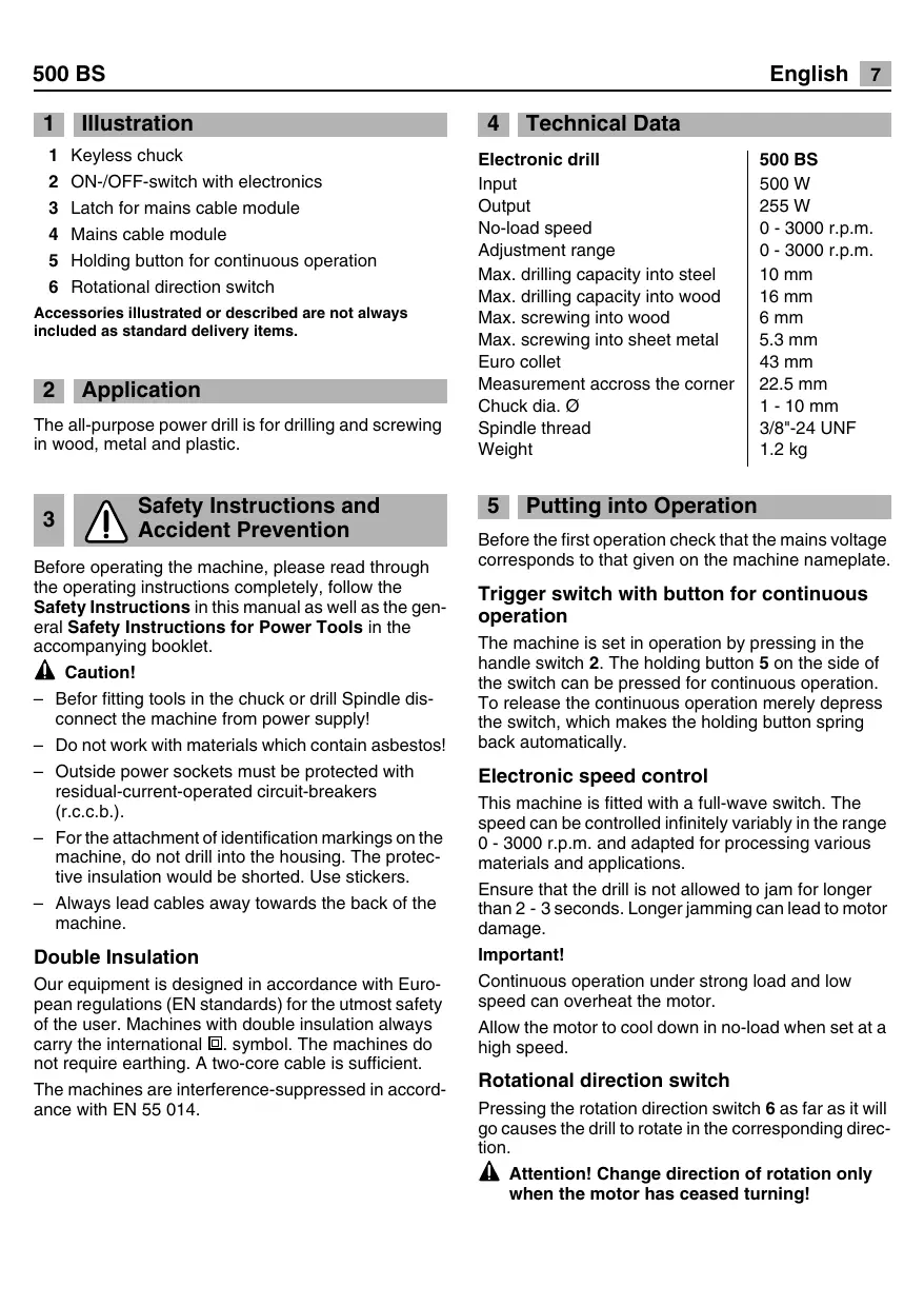
1 Keyless chuck
2 ON-/OFF-switch with electronics
3 Latch for mains cable module
4 Mains cable module
5 Holding button for continuous operation
6 Rotational direction switch
Accessories illustrated or described are not always included as standard delivery items.
2 Application
The all-purpose power drill is for drilling and screwing in wood, metal and plastic.
3! Safety Instructions and Accident Prevention
Before operating the machine, please read through the operating instructions completely, follow the Safety Instructions in this manual as well as the general Safety Instructions for Power Tools in the accompanying booklet.
A Caution!
- Before fitting tools in the chuck or drill Spindle disconnect the machine from power supply!
- Do not work with materials which contain asbestos!
- Outside power sockets must be protected with residual-current-operated circuit-breakers (r.c.c.b.).
- For the attachment of identification markings on the machine, do not drill into the housing. The protective insulation would be shorted. Use stickers.
- Always lead cables away towards the back of the machine.
Double Insulation
Our equipment is designed in accordance with European regulations (EN standards) for the utmost safety of the user. Machines with double insulation always carry the international l symbol. The machines do not require earthing. A two-core cable is sufficient.
The machines are interference-suppressed in accordance with EN 55 014.
4 Technical Data
Electronic drill
Input
Output
No-load speed
Adjustment range
Max. drilling capacity into steel
Max. drilling capacity into wood
Max. screwing into wood
Max. screwing into sheet metal
Euro collet
Measurement accross the corner
Chuck dia.
Spindle thread
Weight
500 BS
500 W
255W
0-3000 r.p.m.
0-3000 r.p.m.
10 mm
16 mm
6 mm
5.3 mm
43 mm
22.5 mm
1-10mm
3/8"-24 UNF
1.2 kg
5 Putting into Operation
Before the first operation check that the mains voltage corresponds to that given on the machine nameplate.
Trigger switch with button for continuous operation
The machine is set in operation by pressing in the handle switch 2. The holding button 5 on the side of the switch can be pressed for continuous operation. To release the continuous operation merely depress the switch, which makes the holding button spring back automatically.
Electronic speed control
This machine is fitted with a full-wave switch. The speed can be controlled infinitely variably in the range 0 - 3000 r.p.m. and adapted for processing various materials and applications.
Ensure that the drill is not allowed to jam for longer than 2 - 3 seconds. Longer jamming can lead to motor damage.
Important!
Continuous operation under strong load and low speed can overheat the motor.
Allow the motor to cool down in no-load when set at a high speed.
Rotational direction switch
Pressing the rotation direction switch 6 as far as it will go causes the drill to rotate in the corresponding direction.
Attention! Change direction of rotation only when the motor has ceased turning!
Operation of the Quick Clamping Drill Chuck
The fully automatic spindle locking makes possible quick and easy changing of the tool in the drill chuck.
Opening: Turn the sleeve in the "AUF" direction.
Clamping: Open the chuck and insert the tool as far as possible.
Firmly clamp the chuck by turning the sleeve in the "ZU" direction.
For soft drill shafts, it may be necessary to retighten after a short time!
6 Dismounting the Drill Chuck
Remove the left-hand threaded screw that secures the drill chuck on the drill spindle against unscrewing in left rotation. The drill chuck can then be loosened by lightly striking a Allen key clamped in the drill chuck and screwed off.
Remounting takes place in the reverse order.
Clean the flat surfaces on the drill chuck and spindle before mounting. Screw on the drill chuck firmly and secure with the safety screw.
Observe in addition that, when using a rim gear drill chuck, the chuck key must not be attached to the machine with chains, cords or similar means.
When drilling or screwdriving, secure the work pieces against being rotated by the drill.
7 Screwing
Make sure that the bit and screw correspond in size and shape.
It is advisable to use socket-head screws since their self-centering action ensures safe work. Or even better - TORX screws and the corresponding bits. Optimal screwing is achieved when the screwing device is fixed securely in the screw head.
Always make sure that the chosen speed is correct for the purpose for which you are using the machine.
When drilling match speed with type of material and drill. High speed drilling in steel and stone will cause premature tool wear.
Use tool steel twist drills for soft materials such as wood and plastics; high speed twist drills for steel and iron.
8 Maintenance Measures
Maintenance
The machine's motor has life-time lubrication and requires no special maintenance. However, should you operate the machine on a continuous basis over long periods of time we recommend that you send us the machine for thorough cleaning and an inspection. This will spare you unnecessary-ary repair expenses and increase the machine's service life. If you always clean the ventilator of dust after each operation, the motor will enjoy an ever longer service life. Uniform ventilation is essential for a long service life.
Replacing carbon brushes
Our service personnel will do this and all other servicing work fast and professionally.
9 Mains cable
Damaged mains cables should not be used. They are to be replaced without delay.
As the result of a innovative mains cable module 4, this is possible in a quick and easy manner. Press the latches 3 on both sides and pull the mains cable module out of the handle. Insert a new mains cable in the handle and latch. Mains cables in various lengths are available as special accessories.
Use the mains cable module provided only for Kress Electro-Tools. Do not attempt to operate other machines with the module.
10 Noise/vibration information
Measured values determined according to EN 60745.
The A-weighted noise level of the machine is typically:
Sound pressure level (LpA) 77 dB(A)
Sound power level (LwA) 88 dB(A)
Measurement uncertainty K = 3 dB
The noise level can exceed 85 dB(A) during operation.Wear hearing protection!
Vibration
Triaxial vibration emission value determined according to EN 60745.
Measured value ah = < 2.5 m/s²
Measurement uncertainty K = 1.5m / s^2
The vibration emission level given in this information sheet has been measured in accordance with a standardised test given in EN 60745 and may be used to compare one tool with another.
The vibration emission level will vary because of the ways in which a power tool can be used and may increase above the level given in this information sheet. This could lead to underestimation of vibration when the tool is used regularly in such a manner.
Note:
To be accurate, an estimation of the level of exposure to vibration experienced during a given period of work should also take into account the times when the tool is switched off and when it is running but not actually when doing the job.
This may significantly reduce the exposure level over the total working period.
11 Environmental Protection

Do not dispose of electric tools together with household waste material!
Recycle raw materials instead of disposing as waste
The machine, accessories and packaging should be sorted for environmental-friendly recycling.
These instructions are printed on recycled paper manufactured without chlorine.
The plastic components are labelled for categorised recycling.
Subject to change without notice
1 Figure
Reservation for andringar
1 Fig.
1 Hurtigspendeborepatron
2 Taend/Sluk-afbryder med elektronik
3 Lås netkabelmodul
4 Netkabelmodul
5 Laseknap til konstant drift
6 Retningsomskifter
HεKtpovikδεθuvσtpoωv
To mnxavna auto eiva Eeonlaioevo ^ eva diakottn
tnpouoc kmuatoc. OI oTpopec mtopoovva puOIOuov
abiabOeta otnv npoxn an0 0-3000 U/min ka va
npoapaoooovtovn entEepyiaota twv diaopowv
uikovkoi c epapoyec.
EniAev npooeEte 0ti To mXavma dev npenei va
mIoKapaei nepiootepo anto 2-3 eutepeAeTTA. Av to
muIokApiaqia dgapkeei nepiaotepo mIpouv va
npoEvnOov bAbaes otov kInntpa.
Σημαντικό!
O Kivntpac mnpoei epiinwn auvexouc kai unepoalnc enipapuvoc e xauhEc oTpopec va unepoepaevbei.
Auñoté tv apiθo στροφw κai φηoTe tv kivntnpa va κpuωσει χωpi φoptio.
DiaikottncΦopac TEPiOTpOphC
NATWvTAC TOV dIaKOTTN POpac NepiOToPooNc 6 Mxpi Tepa NepiOtpEeTai To mXavnma OTNV avtioTox n dieuBuvon.
Anpoooxn!Haalayn oopac nepiaotpoqn npenei va yivetai mvo eakvntooinmuynxavn!
Xeipioooc Tou taxutaoK
CE Declaration of conformity
We declare under our sole responsibility that this product is in conformity with the following standards or standardization documents: see CE
Technical file at: see TF
FR
Quality & Process Representative

Wolfgang Auch
Technischer Leiter
Technical Director
- Dieses Elektrowerkzeug wurde mit hoher Präzisierung gefertigt und unterleitig strengen werkseitigen Qualitätskontrolien.
- Daher garantieren wir die kostenlose Beseitigung von Fabrikations-oder Materialfehlum, die innerhalb von 24 Monaten ab Verkaufsdatum an den Endverbraucher auftreten. Wir behalten uns vor, defekte Teile auszubessern oder durch neue zu ersetzen. Ausgetauschte Teile gehen in unser Eigentum über.
- Unsachgemäß Verwendung oder Behandlung sowie die Öffnung des Gerätes durch nicht autorisierte Reparaturstellen führen zum Erlösenchen der Garantie. Dem Verschleib unterworfene Teile sind von Garantieleistungen ausgeschlossen.
- Garantieansprüche können nur bei unverzüglicher Meldung von Mangeln (auch bei Transportschaden) anerkannt werden. Durch Ausführung von Garantieleistungen wird die Garantiezeit nicht verlangert.
- Bei Störungenitte Gerät mit ausgeführter Garantiekarte und kurzer Mängelbeschreibung an uns oder die zuständige Servicestelle einsenden. Kaufbeleg beifugen.
- Durch die von uns übernommenen Garantie-Verpflichtungen werden alle weitergehendener Ansprüche des Käufers - insbesondere das Recht auf Wandelung, Minderung oder Geltendmachung von Schadenersatzansprüchen - ausgeschlossen.
- Dem Käfer steht jedoch nach seiner Wahl das Recht auf Minderung (Herabsetzung des Kaufpreises) oder Wandelung (Rückgangigmachung des Kaufvertrages) zu, falls es uns nicht geltet, evt. auftretende Mängel innerhalb einer angemessenen Frist zu beseitigen.
- Nicht ausgeschlossen sind die Schadensersatzansprüche nach den §§ 463, 480 Abs. 2,635 BGB wegen Fehlens zugesicherter Eigenschaften.
-
Die Bestimmungen nach Punkt 7 und 8 gesten nur für den Bereich der Bundesrepublik Deutschland.
-
Côt outillage électroportatif a été construit de manière très précise et a fait, en usine, l'objet de contrôleles de qualité très stricts.
- Cela nous permet d'assurer une réparation gratuite des définis de fabrication ou de matériel susceptibles d'être découvertes dans les 24 mois chez l'utilitaire à datede la date d'achat. Nous nous réservons le droit soit de modifier les pieces défectueuses, soit de les échanger contre des nuèves. Les pieces échéçées deviennent alors immédiatement notre propriété.
- Toute utilisation inadaptee, tout traitement inapproprié, toute ouverture de l'outillage effectué par un personnel ou un service non habilité à le faire entraine automatiquement l'extinction de toute revendication relative à cette garantie. Les pièces d'usure sont expressément exclues de cette garantie.
- Les revendications de garantie ne seront etre prises en compte qu'en cas de déclaration immédiate des défauts (avaries dues au transport y compris). L'exécution des prestations de garantie ne donne pas droit a une prolongation de la période de validité de la garantie.
- En cas de dysfonctionnement, veuillez expédier l'appareil avec sa carte de garantie dûment complétée et une brève description des défains à notre adresse ou à la station de service après-vente concernée. Prière de joindre la facture.
- Une prise en charge par nos soins dans le cadre de la garantie, exclut tout autre recours de la part de l'acheteur, en particulier le droit de rétraction, de réduction ou de revendication de dommages-intérêts.
- Cependant, il conserve son droit de rétraction (annulation du contrat de vente) ou de réduction (abaisissement du prix d'achat), selon ses convenances, si nous ne sommes pas en mesure d'éliminer d'éventuels définis dans un décai convenable.
- Ne sont pas exclues, les revendizations de dommages-intérêts selon §§ 463, 480 Al. 2,635 du Code Civil allemand, relatives à l'absence de propriétaires garanties.
-
Les dispositions 7 et 8 ne sont valables que pour l'Allemagne.
-
This electro-tool was manufactured with high precision and subjected to rigorous factory quality controls.
- Therefore, we guarantee the cost-free correction of fabrication or material defects that occur within 24 months of the date of purchase by the end user. We reserve the right to repair defective parts or replace them with new parts. Replaced parts become our property.
- Improper use or handling as well as opening of the machine by unauthorised repair agencies voids the guarantee. Parts subject to wear are excluded from the guarantee.
- The guarantee may only be enforced when defects are reported without undue delay (including shipping damage). Guarantee implementation does not extend the guarantee period.
- If the tool is defective, please complete the guarantee card and return the unit, guarantee card and a brief description of the problem to the responsible service location. Please enclose your sales receipt.
- The guarantee obligations assumed by us shall exclude any further claims on the part of the buyer, in particular the right to recission of a sale, reduction and the assertion of damage claims.
- However, the buyer shall have the right to either a reduction (in the purchase price) or the recission of the sale (cancellation of the sales agreement) should we fail to eliminate any defects within a reasonable period of time.
- Damage claims in accordance with §§ 463, 480 Paragraph 2,635 BGB due to absence of guaranteed quality shall not be not excluded.
-
The provisions defined in Items 7 and 8 only apply to the Federal Republic of Germany.
-
Dit elektrisch gereedschap is vervaardig met grote naukeurighend en isonderhevig aan strengde kwaliteitstcontroles in de fabriek.
- Daarom garanderen wij hetkesteloosverhelpen van fabricage- of materiaalfouten die binnen 24 maanden na de datum van de verkoop aan eindverbruiker optreden. Wij behouden ons hetrecht voor, defecte onderdelen te repareren of door neue te verrangen. Vervangen onderdelen worden ons eigendom.
- Ondeskundig gebruk of ondekundige behandeling alsmede het openen van de machine door nicht erkende reparatiebedrijven leiden tot verleys van de garantie. Onderdenen die aan slijtage onderhevig zijn,+zijn van de garantie uitsgesloten.
- Er kan slechts aanspraak op garantie verleend worden als de schade onverwijd gemeld ward (ook bij transportschade). Er volgt geen verlenging van de garantieperiode na uitvoering van garantieprestaties.
- Gleeive in geval van storing de machine met ingevulde garantie-bon en een korte beschrijving van de schade aan ons of aan een bevoegde service-dienst in te sturen. Cassabon bijvoegen.
- Door de door ons opgenomen garantieverpflichtingen zijn alle verdere aanspraken van de koper - met name hetrecht op koopvernietiging, prijsreductie of het eisen van schadevergoeding - uitgesloten.
- De koper hebelt zich aankeuze hetrecht op prijsreductie (vermindering van de aankoopprijs) of op koopvermietiging (annuleren van het koopcontract), indien wij er niert in slagen, eventuele opgetreden defecten binnen een redelijkte termijn te herstellen.
- Niet uitgesloten zijn de eisen van schadevergoeding volgens §§ 463, 480 alinea. 2,635 BGB wegens Niet bestaande, toegekende eigenschappen.
- De bepalingen onder punt 7 en 8 gelden alleen maar voor de Bondsrepubliek Duitsland.
1
Garanzia
- Application
- 3! Safety Instructions and Accident Prevention
- A Caution!
- Double Insulation
- Technical Data
- Electronic drill
- Putting into Operation
- Trigger switch with button for continuous operation
- Electronic speed control
- Important!
- Rotational direction switch
- Operation of the Quick Clamping Drill Chuck
- Dismounting the Drill Chuck
- Screwing
- Maintenance Measures
- Maintenance
- Replacing carbon brushes
- Mains cable
- Noise/vibration information
- Vibration
- Note:
- Environmental Protection
- Figure
- Fig.
- HεKtpovikδεθuvσtpoωv
- Σημαντικό!
- DiaikottncΦopac TEPiOTpOphC
- Xeipioooc Tou taxutaoK
- CE Declaration of conformity
- FR
- 1
- Garanzia
Brand : KRESS
Model : 500 BS
Category : Electric drill