
1050 SXC - Electric drill KRESS - Free user manual and instructions
Find the device manual for free 1050 SXC KRESS in PDF.
| Brand | KRESS |
| Model | 1050 SXC |
| Product type | Electric percussion drill |
| Power input | 1050 W |
| Power output | 600 W |
| Number of speeds | 2 |
| No-load speed (speed I) | 150-950 rpm |
| No-load speed (speed II) | 300-2250 rpm |
| Impact rate | n × 24 blows/min |
| Max. drilling diameter (steel) | 16 mm |
| Max. drilling diameter (wood) | 60 mm |
| Max. drilling diameter (concrete) | 20 mm |
| Max. screw diameter (wood) | 10 mm |
| Max. screw diameter (sheet metal) | 8 mm |
| Collar diameter | 43 mm |
| Chuck | Keyless chuck Ø 13 mm |
| Spindle thread | 1/2" × 20 UNF |
| Weight | 2.56 kg |
| Main functions | Impact drilling, drilling, screwdriving, tapping; left/right rotation; electronic speed control; torque preselection; safety slip clutch; spindle lock |
| Power supply | Mains, modular cable |
| Double insulation | Yes |
| Maintenance and cleaning | Clean the fan after each use; permanent motor lubrication; replace carbon brushes at authorized service center |
| Safety | Slip clutch; switch lock; chuck lock; auxiliary handle mandatory |
| Spare parts and repairability | Interchangeable mains cable module; replaceable chuck and carbon brushes; authorized service center |
| Warranty | 24 months, manufacturing defects |
| General information | Sound pressure level: 74+3 dB(A); sound power level: 87+3 dB(A); workplace emission value: 77+3 dB(A) |
Frequently Asked Questions - 1050 SXC KRESS
User questions about 1050 SXC KRESS
0 question about this device. Answer the ones you know or ask your own.
Ask a new question about this device
Download the instructions for your Electric drill in PDF format for free! Find your manual 1050 SXC - KRESS and take your electronic device back in hand. On this page are published all the documents necessary for the use of your device. 1050 SXC by KRESS.
USER MANUAL 1050 SXC KRESS
Electronic Percussion drill
Operating Instructions
| Electronic-Torque-Control | |||
| ∅ | Torque-Control | ||
| ∅ 4,0 | A | II | 1-2 |
| ∅ 5,0 | A | II | 1-3 |
| ∅ 6,0 | A | II | 4-9 |
| ∅ 8,0 | A | I | 6-10 |
| ∅ 10,0 | B | I | 8-10 |
1 ON/OFF switch with full wave electronic control and adjusting wheel for speed selection
2 Holding button for continuous operation
3 Change-over switch
4 Adjusting wheel for torque selection (Model 1050 SXC only)
5 Switching from normal drilling to percussion drilling
6 Mechanical 2-speed gearshift with LOCK switch (spindle locking)
7 Mains cable module
8 Locking device for mains cable module
9 Quick-change chuck
11 Auxiliary handle
| Technical data | 800 SX | 1050 SXC |
| Input | 800 W | 1050 W |
| Output | 430 W | 600 W |
| Full wave modulation | x | |
| Full wave control | x | |
| Rotation right/left | x | x |
| No. of speed ranges | 2 | 2 |
| No-load speed r.p.m. 1st gear | 0-1400 | 150-950 |
| 2nd gear | 0-3300 | 300-2250 |
| Load speed r.p.m. 1st gear | 850 | 900 |
| 2nd gear | 1970 | 2100 |
| Percussion rate p.m. | n x 24 | n x 24 |
| max. drill dia. into steel mm | 13 | 16 |
| max. drill dia. into wood mm | 30 | 60 |
| max. percussion drill dia into concrete mm | 18 | 20 |
| max. screwing into wood mm | 8 | 10 |
| max. screwing into sheet metal mm | 6.3 | 8 |
| Collar diameter, mm | 43 | 43 |
| Width across corners mm | 43 | 43 |
| Chuck dia., mm | 13 | 13 |
| Spindle thread | 1/2" x 20 UNF | |
| Weight kg | 2.34 | 2.56 |
Use
The drill is universally applicable for percussion drilling in rock, drilling and putting screws into wood, metal, and synthetics, and for tapping.
Safety instructions and prevention of accidents
Before operating the machine, please read through the operating instructions completely, follow the Safety Instructions in this manual as well as the general Safety Instructions for Power Tools in the accompanying booklet.
Caution!
- Beware of jamming. The machine may jam, for example, when the machine is at an angle or when the drill bit comes into contact with reinforcing steel!
- Before mounting tools in the drill chuck or spindle, always move the reversing switch (3) to the middle LOCK position, or disconnect the machine from the power supply, or remove the mains cable module (7) from the grip using the locking device button (8).
- Do not work with materials containing asbestos!
- Outside power sockets must be protected with residual-current-operated circuit-breakers (r.c.c.b.).
- Do not drill holes into the housing to label the machine. The protective insulation will be bridged. Please use self-adhesive labels.
Always lead cables away towards the back of the machine.
Double insulation
Our equipment is designed in accordance with European regulations (EN standards) for the utmost safety of the user. Machines with double insulation always carry the in
ternational symbol. The machines do not require earth- hing. A two-core cable is sufficient.
The machines are interference-suppressed in accordance with EN 55014.
Initial operation
Before the first operation check that the mains voltage corresponds to that given on the machine nameplate.
Trigger switch with button for continuous operation
The machine is set in operation by pressing in the handle switch (1). The small holding button (2) on the side of the switch is pressed in for continuous operation. To release the continuous operation merely depress the switch, which makes the holding button spring back automatically.
Electronic speed control
This machine has an integrated full wave electronic control circuit switch.
The required speed may be selected with the adjusting wheel (e.g. for serial screw drilling or for cutting threads). The switch is lockable in every position.
Position A = lowest speed
Position G = highest speed
Ensure that the drill is not allowed to jam for longer than 2-3 seconds. Longer jamming can lead to motor damage.
Important!
Continuous operation under strong load and low speed can overheat the motor. Allow the motor to cool down in no-load when set at a high speed!
Torque-selection + electronic safety system
(Model 1050 SXC only)
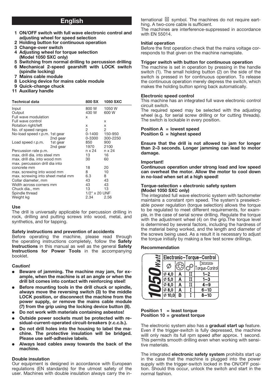
The integrated full wave electronic system with tachometer maintains a constant rpm speed. The system's preselectable power regulation (torque selection) allows the torque to be regulated to meet different requirements, for example, in the case of serial screw drilling. Regulate the torque with the adjustment wheel (4) on the grip. The torque level is determined by several factors, including the hardness of the material being worked, and the length and diameter of the screws being used. As a result it is necessary to adjust the torque initially by making a few test screw drillings.
Recommendation
| Electronic-Torque-Control | |||
| ∅ | e | e | Torque-Control |
| ∅ 4,0 | A | II | 1-2 |
| ∅ 5,0 | A | II | 1-3 |
| ∅ 6,0 | A | II | 4-9 |
| ∅ 8,0 | A | I | 6-10 |
| ∅ 10,0 | B | I | 8-10 |
Position 1 = least torque
Position 10 = greatest torque
The electronic system also has a gradual start up feature. Even if the trigger-switch is fully depressed, the machine will only reach its full rpm speed after approx. 1 second. This permits smooth drilling even when working with sensitive materials.
The integrated electronic safety system prohibits start up in the case that the machine is plugged into the power supply with the trigger-switch locked in the ON/OFF position. Should this occur, unlock the switch and start in the normal fashion.
Changing direction of rotation (main rotation - clockwise)
The direction of rotation of the spindle is altered by the reversing switch (3).
R = Clockwise (Right)
L = Anticlockwise (Left)
Important! Press the rotational direction switch 9 in each case to the stop on the housing, i.e. until it can be felt to engage.
The reversing switch is easiest to operate by using the thumb and index or middle finger from both sides.
Attention!
Change direction of rotation only when the motor has ceased turning!
When using the drill as a screwdriver, the percussion mechanism must be switched off. Switch-over by means of the sliding switch (5).
When fixed in the middle LOCK position, the reversing switch prevents accidental startup of the full wave control (1), for example when changing tools or mounting/removing the drill chuck.
Percussion drilling device
The machine has an integrated percussion mechanism and can be switched from normal drilling to percussion drilling. The sliding switch (5) allows switching from normal drilling to percussion drilling or vice-versa while the machine is in operation.
Normal drilling position
Push slide switch (5) to the left in direction of "normal drilling".
Percussion drilling position
Push slide switch (5) to the right in direction of "percussion drilling".
Mechanical two-speed gearshift
Shifting takes place by turning the finger-grip knob (6) on the upper side of the machine.
Position 1 = slow machine speed
Position 2 = fast machine speed
The two-speed gearing offers advantages for drilling and percussion drilling with small drill diameters up to c. 8 mm (shift gear to position 2). For larger drill diameters and for mixing work, shift gear to position 1.
The LOCK function (finger-grip knob (6) in LOCK position) is useful when mounting and removing the drill chuck. The LOCK position also facilitates wrench-free tool changes when using a quick-change chuck and allows maximum clamping force in tool mounting.
Safety slip coupling
The slip coupling takes effect as soon as a tool clamped in the machine becomes overloaded, is braked abruptly or jams. Although the motor and gear continue to run, the tool remains stationary. Thus, the motor and gear are protected against overload, impulsive gearwheel loading is ruled out.
Quick-change chuck
This chuck has been specially developed for use on percussion drills.
The chuck has a release safety lock which prevents any unintentional release of drilling tool even at high impact frequencies.
Operation by turning collar as usual to stop point. Engagement of clamping force safety lock for subsequent operation is clearly heard and felt.
Clamping and releasing of chuck by holding the locking ring.
Use as a screwdriver
Screwdriver inserts (bits) can fitted directly into the chuck. Use Phillips screws for best results. Safe operation is ensured by the self-centering mechanism. Please make sure to use the correct screwdriver inserts.
Cutting threads
The integrated electronic and the reversal of the direction of rotation makes the percussion drill also suitable for cutting threads. The use of machine taps is recommended. The tap is clamped into the chuck. The electronic controls are sensitive and should be handled with utmost care to prevent any breaking of tap - particularly when cutting threads into blind holes.
The required torque may be selected via the adjusting wheel in switch (1) and via the torque selection (4).
Important! When cutting threads, use low speeds only.
Important note for machines with clockwise and anticlockwise rotation.
Reassembly of drill chuck:
Caution!
Before disassembling and reassembling the drill chuck, disconnect the machine from the power supply, or remove the mains cable module (6) from the grip using the locking device button (7).
Caution!
Before removing and mounting the drill chuck, always move the reversing switch (3) to the LOCK position. By doing so, you eliminate the risk of accidentally triggering the full wave switch (1).
If a faulty chuck has to be replaced, please check whether the chuck is secured to the drill spindle with a safety screw. This screw must be removed first (Attention! Left-handed screw! Turn clockwise!).
The chuck can be loosened and unscrewed by lightly hitting a hexagon socket key (Allen key) which has been fitted in the chuck. It is refitted by repeating the procedure backwards.
Caution: Before fitting a new chuck please clean the end faces on the chuck and drill spindle.
Tighten the new chuck securely (30 Nm). Secure the chuck with the safety screw is there is one (Tighten the safety screw in anti-clockwise direction).
Caution!
It is still possible, especially when there is no safety screw, that the chuck comes off the drill spindle when it is turning in the anticlockwise direction. For this reason, when changing the chuck ensure that it is fitted onto the spindle perfectly.
Always make sure that the chosen speed is correct for the purpose for which you are using the machine.
High speeds are necessary for polishing and grinding. When drilling match speed with type of material and drill. High speed drilling in steel and stone will cause premature tool wear.
Use tool steel twist drills for soft materials such as wood and plastics; carbide-tipped stone drills for stone and concrete; high speed twist drills for steel and iron.
Also make sure that, using a gear-rim-chuck, the drill chuck key is never fastened to the drill with chains, strings or by similar means. Be sure that the workpiece cannot be taken along by the drill.
Maintenance
The machine's motor has life-time lubrication and requires no special maintenance. However, should you operate the machine on a continuous basis over long periods of time we recommend that you send us the machine for thorough cleaning and an inspection. This will spare you unnecessary repair expenses and increase the machine's service life. If you always clean the ventilator of dust after each operation, the motor will enjoy an ever longer service life. Uniform ventilation is essential for a long service life.
Replacing carbon brushes
Our service personnel will do this and all other servicing work fast and professionally.
Mains cable
Damaged mains cables must not be used. They are to be replaced immediately.
This has been made very straightforward by the new mains cable module (6). Press both locking keys (7) and pull the mains cable module (6) out of the handle. Insert the new mains cable into the handle and lock in place. Different lengthed mains cables are available as special accessories. Only use the mains cable module for KRESS power tools! Do not attempt to operate other electrical appliances with it!
Auxiliary handle
For safety reasons, the supplementary handle must always be used when working with the percussion drilling machine. It allows safe, wander-free guidance of the drill and, thanks to an integrated depth stop, precise adjustment of the drilling depth.
Ensure that the draw spindle is properly tightened to the auxiliary handle. Only in this way can you prevent the auxiliary handle from twisting on the collar or becoming detached from the equipment.
Supplied accessories
Auxiliary handle with depth stop
Noise/vibration information
Measured values correspond with EN 50144.
Sound pressure level: 1050 SXC = 74+3 dB (A)
800 SX = 78+3 dB (A)
Sound power level: 1050 SXC = 87^+3 dB (A)
800 SX = 91+3 dB (A)
Work place
emission value: 1050 SXC = 77^+3 dB (A)
800 SX = 81+3 dB (A)
Operators require noise protection equipment.
The weighted acceleration is typically 13.2m / s^2
Environmental protection
Kress takes back used machines for resource saving recycling. Due to their modular construction Kress machines can be very easily broken down into their recyclable basic materials. Hand in your old Kress machine at a dealer or send them directly to Kress.
Subject to change without notice.
| Electronic-Torque-Control | |||
| ∅ | Torque-Control | ||
| ∅ 4,0 | A | II | 1-2 |
| ∅ 5,0 | A | II | 1-3 |
| ∅ 6,0 | A | II | 4-9 |
| ∅ 8,0 | A | I | 6-10 |
| ∅ 10,0 | B | I | 8-10 |
Position 1 = couple de rotation minimal
Position 10 = couple de rotation maximal
Position de percussion
| Electronic-Torque-Control | |||
| ∅ | Torque-Control | ||
| ∅ 4,0 | A | II | 1-2 |
| ∅ 5,0 | A | II | 1-3 |
| ∅ 6,0 | A | II | 4-9 |
| ∅ 8,0 | A | I | 6-10 |
| ∅ 10,0 | B | I | 8-10 |
800 SX = 78+3 dB (A)
Geluidsvermogenniveau: 1050 SXC = 87+3 dB (A)
800 SX = 91+3 dB (A)
Emissiewaarde met
betrekking tot de
| Electronic-Torque-Control | |||
| ∅ | Torque-Control | ||
| ∅ 4,0 | A | II | 1-2 |
| ∅ 5,0 | A | II | 1-3 |
| ∅ 6,0 | A | II | 4-9 |
| ∅ 8,0 | A | I | 6-10 |
| ∅ 10,0 | B | I | 8-10 |
800 SX = 78+3 dB (A)
| Electronic-Torque-Control | |||
| ∅ | Torque-Control | ||
| ∅ 4,0 | A | II | 1-2 |
| ∅ 5,0 | A | II | 1-3 |
| ∅ 6,0 | A | II | 4-9 |
| ∅ 8,0 | A | I | 6-10 |
| ∅ 10,0 | B | I | 8-10 |
Posión 1 = par de giro minimo
$$ 8 0 0 S X = 9 1 ^ {+ 3} d B (A) $$
| Electronic-Torque-Control | |||
| ∅ | e | o | Torque-Control |
| ∅ 4,0 | A | II | 1-2 |
| ∅ 5,0 | A | II | 1-3 |
| ∅ 6,0 | A | II | 4-9 |
| ∅ 8,0 | A | I | 6-10 |
| ∅ 10,0 | B | I | 8-10 |
800 SX = 78+3 dB (A)
Ljudeffektsnivå: 1050 SXC = 87+3 dB (A)
800 SX = 91+3 dB (A)
Emissionsvärde pa
Reservation for andringar.
Dansk
1 Taend/sluk-kontakt med helbolgeelektronik og ind-stillingshjul til forvalg af omdrejningstal
2 Laseknap til konstant drift
3 Kontakt for hore-/venstrelob
4 Stillehujl for forvalg af omdrejningsmoment (kun model 1050 SXC)
5 Omskifterskyder for boring og slagboring
6 Mekanisk 2-gearskiffe med LOCK-kontakt (spindellås)
7Netkabel-modul
8 Låsning for netkabelmodul
9 Hurtigspændings-borepatron
11 Ekstrahandgreb
| Tekniske data | 800 SX | 1050 SXC | |
| Optagen effekt | 800 W | 1050 W | |
| Afgivet effekt | 430 W | 600 W | |
| Helbøgestyring | x | ||
| Helbøgeregulering | x | ||
| Højre-/venstrlæb | x | x | |
| Antal gear | 2 | 2 | |
| Tomgangsombdrejningstal o/min | I gear | 0-1400 | 150-950 |
| II gear | 0-3300 | 300-2250 | |
| Belastrningsombdrejningstal o/min | I gear | 850 | 900 |
| II gear | 1970 | 2100 | |
| Slagtal 1/min | n x 24 | n x 24 | |
| Boring i stål max. Ø mm | 13 | 16 | |
| Boring i træ max. Ø mm | 30 | 60 | |
| Slagboring i beton max. Ø mm | 18 | 20 | |
| Skrunig i træ max. Ø mm | 8 | 10 | |
| Skrunig i metal max. Ø mm | 6,3 | 8 | |
| Spændhalsdiameter Ø mm | 43 | 43 | |
| Hjørnmål mm | 43 | 43 | |
| Borepatronstorrelse Ø mm | 13 | 13 | |
| Spindelgevind | 1/2" x 20 UNF | ||
| Vægt kg | 2,34 | 2,56 | |
Anyendelse
Boremaskinen kan anvendes overalt til slagboring i sten, til boring og skrunig i træ, metal og kunststof som til gelevidskæring.
| Electronic-Torque-Control | |||
| ∅ | Torque-Control | ||
| ∅ 4,0 | A | II | 1-2 |
| ∅ 5,0 | A | II | 1-3 |
| ∅ 6,0 | A | II | 4-9 |
| ∅ 8,0 | A | I | 6-10 |
| ∅ 10,0 | B | I | 8-10 |
Stilling 1 = mindste drejningsmoment
Stilling 10 = største drejningsmoment
| Electronic-Torque-Control | |||
| ∅ | Torque-Control | ||
| ∅ 4,0 | A | II | 1-2 |
| ∅ 5,0 | A | II | 1-3 |
| ∅ 6,0 | A | II | 4-9 |
| ∅ 8,0 | A | I | 6-10 |
| ∅ 10,0 | B | I | 8-10 |
Stilling 1 = lavesto dreiemoment
Stilling 10 = hoyeste dreiemoment
Elektronikken er dessuten utstyr med en mykstart. Selv om man trykker bryteren welt inn, vil/DDE maskinen fopthastighet fere tetter ca. ett sekket. Denne funksjonen gjor det mulig med en myk boresetl selv i skjort material.
Den integrazione sikkerhetseleukonikken forbinder at maskinen starter hvis du en aller annen gigi vanvare skulle komme til a kople den til lysnettet med last PA-/AV-bryter.
I et slijk tilfelle mä du lose strombryteren og starte maskinen på vanlig mæte.
800 SX = 78+3 dB (A)
Lydeffektsnivå: 1050 SXC = 87+3 dB (A)
800 SX = 91+3 dB (A)
Arbeidsplasrelatert
Endringer forbeholds.
Suomi
| Electronic-Torque-Control | |||
| ∅ | Torque-Control | ||
| ∅ 4,0 | A | II | 1-2 |
| ∅ 5,0 | A | II | 1-3 |
| ∅ 6,0 | A | II | 4-9 |
| ∅ 8,0 | A | I | 6-10 |
| ∅ 10,0 | B | I | 8-10 |
Aänen painetaso: 1050 SXC = 74+3 dB (A)
800 SX = 78+3 dB (A)
Äänen tehtaso: 1050 SXC = 87+3 dB (A)
800 SX 91+3 dB (A)
| Electronic-Torque-Control | |||
| ∅ | e | e | Torque-Control |
| ∅ 4,0 | A | II | 1-2 |
| ∅ 5,0 | A | II | 1-3 |
| ∅ 6,0 | A | II | 4-9 |
| ∅ 8,0 | A | I | 6-10 |
| ∅ 10,0 | B | I | 8-10 |
Alambdaipopac stpopoov
(BaoiKn φopa «Δεξiδ»)
Took taxiaac ouoipiyens
AUToTOxOeXeXeXeIaYiaTIVeapApoyN OE KPOUAtKaDpAnava.
To taok exi aopalia aoivjatoc, nou eumodie tny akouia xaapawon tou pvaaleiou, akojn kal o uynacx auovnttek kpuanc.
Enavatonoθεηn tou took:
Ppoooxn!
Npiv Tny anoovapuoloynan kai enavatonoBETnou Tou kbyalte to kalwio ano Tny npica, naapaieote Tn maovada kalwioiu (6) ano Tn labn natovtasTic mavdaawoeic (7).
Ppoooxn!
Niv tv apaipean kai enavatoonetan tou taok yupiote tov diakotn aalaync opac npiotpawv (3) stn chean LOCK. Me autov tov tpno anopeuyetai naakouia laitoupyia tou diakotn nektpovikc diuuvoc1.
Ataai kai oio: Tpuavi onipal HSS (ataaui uynawv ano0oewv).
Mny Kpejate n otepewte To kEidi Taok μe aluoidec, Okoivia npapouoia avtikeiEvva oTo 8panavo kai npoeixetvea mnpapauovpota uAikia evyaic ano to tpuavi.
Suvtnpnon
O kivntnpac tnc unxavn6 evai moviva ypaapiauevo ka dev xpeiaetzai ibaitepn auvttnpno. Zepinwnou nou xpanoioeite evtatika Tnnxavn va mydAo xpvikdoa tna, uovitoume va tvn aooteilete sto oepic mac ia kaqapiauo kai texviko Eeyxo. Etai Egoiokoeide Eooiaeukw kai aevate nty diapkeia zwnc tnc unxvnc oac. Meta ano maakpa leitoupyia evai kalo va quoate tn okovn ano tov aveuipnpa, yiati o staepeoc Eaepiauc oivan umaykios vta th diapkeia cwns nnc unxavn6.
AvtikataaTaonTovyKtpow
Autn Tnv epyaioia kai aAee c npyaicc epbetaie dEayou ynpyopa kai owta ta Eouoiootneva ouvepeia mac.
Kaλωδio
a apéva Kaδδia dev eπitpenetai va xnpoiouotouvi. Pnevi a vvtikaiotwiayi aueoew.
Auto np e1 vaivei xapi tnc movabac kaawoiou peu uatoc (6) eTov nio anlo Tpno. Niote ta duo aykiotpa mavadawonc (7) kai tpaBnTe Tn movada kaawoiou (6) ano tn laBn, TomoEtnote Tn vea movada kalwiou ot nlaBn kai mavadowte Tn. Kaawia o diapopa mkn unapxouov av EidiKO EApTma.
XpəniəmoiTe Tn movda KaAωdiou mvo y Ta nλeKtpika εpyaεia tnc KRESS! Mny pOoataησεν aLeitoupyaetae με autiv dAee nλeKtpike oukeuec.
Enipoo8eTn xepoala
Ia loyous aopaleia npentkata tn xpnon tou kpooutikou 0panavou va xnpoiotoei tai navaT enpoo3en XeipolaB. AieukoUevn aopaan ohyou Tov 0spanavou kai nvy akpni puOmuon Tou baohus tpuimatoc me tv onyobabous.
800 SX = 78+3 dB (A)
- This electrical tool has been designed with high precision and was approved after undergoing strict quality control checks in the factory.
- We are therefore able to guarantee free servicing of any production or material faults which arise in the 24 months after the date of sale to the purchaser. We reserve the right to repair defective parts or else replace them with new parts. Parts which have been replaced become our property.
- The guarantee will be rendered void if the device is used improperly, mistreated or opened up by unauthorised repair personnel. Parts which are subject to wear are not covered by the guarantee.
- The guarantee may only be enforced when defects are reported without undue delay (including shipping damage). Guarantee implementation does not extend the guarantee period.
- If the tool is defective, please complete the guarantee card and return the unit, guarantee card and a brief description of the problem to the responsible service location. Please enclose your sales receipt.
- The guarantee obligations assumed by us shall exclude any further claims on the part of the buyer, in particular the right to recission of a sale, reduction and the assertion of damage claims.
- However, the buyer shall have the right to either a reduction (in the purchase price) or the recession of the sale (cancellation of the sales agreement) should we fail to eliminate any defects within a reasonable period of time.
- Damage claims in accordance with §§ 463, 480 Paragraph 2, 635 BGB due to absence of guaranteed quality shall not be not excluded.
- The provisions defined in Items 7 and 8 only apply to the Federal Republic of Germany.
Garantie
GB CE Declaration of conformity
We declare under our sole responsibility that this product is in conformity with the following standards or standardization documents: see below
Manager of Product Development

Josef Leins,
Quality Assurance Manager
Service-Anschriften / After sales service / Service après-venture
Westcross Centre, 15 Shield Drive
Brentford TW8 9EX
Phone: +44-(0)208-560 0885 - Telefax: +44-(0)208-847 0790
E-mail: njtoolsbrentford@btopenworld.com
Portugal
Sarraipa S.A.
Please fill in immediately and keep in safe place.
- Electronic Percussion drill
- Use
- Safety instructions and prevention of accidents
- Caution!
- Double insulation
- Initial operation
- Trigger switch with button for continuous operation
- Electronic speed control
- Position A = lowest speed
- Position G = highest speed
- Important!
- Torque-selection + electronic safety system
- (Model 1050 SXC only)
- Position 1 = least torque
- Position 10 = greatest torque
- Changing direction of rotation (main rotation - clockwise)
- Attention!
- Percussion drilling device
- Normal drilling position
- Percussion drilling position
- Mechanical two-speed gearshift
- Position 1 = slow machine speed
- Position 2 = fast machine speed
- Safety slip coupling
- Quick-change chuck
- Use as a screwdriver
- Cutting threads
- Maintenance
- Replacing carbon brushes
- Mains cable
- Auxiliary handle
- Supplied accessories
- Noise/vibration information
- Environmental protection
- Position de percussion
- Dansk
- Ekstrahandgreb
- Anyendelse
- Stilling 1 = mindste drejningsmoment
- Stilling 10 = største drejningsmoment
- Stilling 1 = lavesto dreiemoment
- Stilling 10 = hoyeste dreiemoment
- Suomi
- Alambdaipopac stpopoov
- (BaoiKn φopa «Δεξiδ»)
- Took taxiaac ouoipiyens
- Enavatonoθεηn tou took:
- Ppoooxn!
- Suvtnpnon
- AvtikataaTaonTovyKtpow
- Kaλωδio
- Enipoo8eTn xepoala
- Garantie
- GB CE Declaration of conformity
- Service-Anschriften / After sales service / Service après-venture
- Portugal
- Sarraipa S.A.
Brand : KRESS
Model : 1050 SXC
Category : Electric drill