
231 SHAPER ROUTER TABLE - Milling table DREMEL - Free user manual and instructions
Find the device manual for free 231 SHAPER ROUTER TABLE DREMEL in PDF.
| Product type | Router Table (Shaper Router Table) |
| Brand | DREMEL |
| Model | 231 |
| Use | Accessory for rotary tool, converts into a routing/shaping table |
| Rotary tool compatibility | DREMEL 300, 395, 398, 400, 4000 |
| Material | Metal and plastic |
| Power supply | Via the rotary tool (not included) |
| Adjustable cutting depth | Yes, with adjustment knob; graduations in inches (1/8) and millimeters (5 mm) |
| Parallel guide | Yes, movable with large knob |
| Router bit guard | Adjustable height central cylinder |
| Support wedge | Yes, adjustable to guide the workpiece |
| Push stick | Recommended for small pieces; can be homemade (wood 2x50x200 mm) |
| Safety | On/Off switch facing forward; stop by left-right movement |
| Maintenance and cleaning | Clean after use, check fastenings, keep work area clean |
| Spare parts and repairability | Have repairs done by a qualified repair person; identical replacement parts |
| Warranty | In compliance with legal regulations; excludes normal wear, overload, improper use |
| Manual | 84 pages, available in multiple languages |
Frequently Asked Questions - 231 SHAPER ROUTER TABLE DREMEL
User questions about 231 SHAPER ROUTER TABLE DREMEL
0 question about this device. Answer the ones you know or ask your own.
Ask a new question about this device
Download the instructions for your Milling table in PDF format for free! Find your manual 231 SHAPER ROUTER TABLE - DREMEL and take your electronic device back in hand. On this page are published all the documents necessary for the use of your device. 231 SHAPER ROUTER TABLE by DREMEL.
USER MANUAL 231 SHAPER ROUTER TABLE DREMEL
Dremel Europe The Netherlands
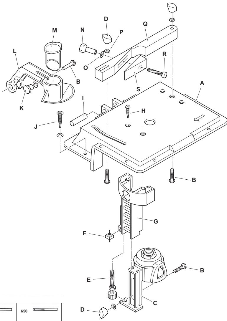
FIG.1
| 612 | 650 |
| 615 | 652 |
| 640 | 654 |
| 655 | |

WARNING
READ ALL INSTRUCTIONS.
Failure to follow all instructions
listed below may result in electric shock, fire and/or serious injury. The term "power tool" in all of the warnings listed below refers to your mains-operated (cored) power tool.
SAVE THESE INSTRUCTIONS
WORK AREA
a. Keep work area clean and well lit. Cluttered and dark areas invite accidents.
b. Do not operate power tools in explosive atmospheres, such as in the presence of flammable liquids, gases or dust. Power tools create sparks which may ignite the dust or fumes.
c. Keep children and bystanders away while operating a power tool. Distractions can cause you to lose control.
ELECTRICAL SAFETY
a. Power tool plugs must match the outlet. Never modify the plug in any way. Do not use any adapter plugs with earthed (grounded) power tools. Unmodified plugs and matching outlets will reduce risk of electric shock.
b. Avoid body contact with earthed or grounded surfaces such as pipes, radiators, ranges and refrigerators. There is an increased risk of electric shock if your body is earthed or grounded.
c. Do not expose power tools to rain or wet conditions. Water entering a power tool will increase the risk of electric shock.
d. Do not abuse the cord. Never use the cord for carrying, pulling or unplugging the power tool. Keep cord away from heat, oil, sharp edges or moving parts. Damaged or entangled cords increase the risk of electric shock.
e. When operating a power tool outdoors, use an extension cord suitable for outdoor use. Use of a cord suitable for outdoor use reduces the risk of electric shock.
f. If operating a power tool in a damp location is unavoidable, use an earth leakage circuit breaker. Use of an earth leakage circuit breaker reduces the risk of electric shock.
PERSONAL SAFETY
a. Stay alert, watch what you are doing and use common sense when operating a power tool. Do not use a power tool while you are tired or under the influence of drugs, alcohol or medication. A moment of inattention while operating power tools may result in serious personal injury.
b. Use safety equipment. Always wear eye protection. Safety equipment such as dust mask, non-skid safety shoes, hard hat, or hearing protection used for appropriate conditions will reduce personal injuries.
c. Avoid accidental starting. Ensure the switch is in the off position before plugging in. Carrying power tools with your finger on the switch or plugging in power tools that have the switch on invites accidents.
d. Remove any adjusting key or wrench before switching the power tool on. A wrench or a key left attached to a rotating part of the power tool may result in personal injury.
e. Do not overreach. Keep proper footing and balance at all times. This enables better control of the power tool in unexpected situations.
f. Dress properly. Do not wear loose clothing or jewellery. Keep your hair, clothing and gloves away from moving parts. Loose clothes, jewellery or long hair can be caught in moving parts.
g. If devices are provided for the connection of dust extraction and collection facilities, ensure these are connected and properly used. Use of these devices can reduce dust related hazards.
h. Do not work materials containing asbestos (asbestos is considered carcinogenic).
i. Take protective measures when during work dust can develop that is harmful to one's health, combustible or explosive (some dusts are considered carcinogenic); wear a dust mask and work with dust/ chip extraction when connectable.
POWER TOOL USE AND CARE
a. Do not force the power tool. Use the correct power tool for your application. The correct power tool will do the job better and safer at the rate for which it was designed.
b. Do not use the power tool if the switch does not switch it on and off. Any power tool that cannot be controlled with the switch is dangerous and must be repaired.
c. Disconnect the plug from the power source before making any adjustments, changing accessories, or storing power tools. Such preventive safety measures reduce the risk of starting the power tool accidentally.
d. Store idle power tools out of the reach of children and do not allow persons unfamiliar with the power tool or these instructions to operate the power tool. Power tools are dangerous in the hands of untrained users.
e. Maintain power tools. Check for misalignment or binding of moving parts, breakage of parts and any other condition that may affect the power tools operation. If damaged, have the power tool repaired before use. Many accidents are caused by poorly maintained power tools.
f. Keep cutting tools sharp and clean. Properly maintained cutting tools with sharp cutting edges are less likely to bind and are easier to control.
g. Use the power tool, accessories and tool bits etc., in accordance with these instructions and in the manner intended for the particular type of power tool, taking into account the working conditions and the work to be performed. Use of the power tool for operations different from those intended could result in a hazardous situation.
h. Use clamps or other practical way to secure and support the workpiece on a stable platform.
i. Use only genuine accessories.
SERVICE
a. Have your power tool serviced by a qualified repair person using only identical replacement parts. This will ensure that the safety of the power tool is maintained.
SAFETY INSTRUCTIONS FOR ROUTERS
GENERAL
This tool should not be used by people under the age of 16 years.
Always disconnect plug from power source before making any adjustment or changing any accessory.
ACCESSIONS
- Use only accessories with an allowable speed matching at least the highest no-load speed of the tool.
- Do not use damaged or deformed router bits.
- Only use sharp router bits.
- Protect accessories from impact, shock and grease.
BEFORE USE
- Avoid damage that can be caused by screws, nails and other elements in your workpiece; remove them before you start working.
Always check that the supply voltage is the same as the voltage indicated on the nameplate of the tool (tools with a rating of 230V or 240V can also be connected to a 220V supply). -
Dust from material such as paint containing lead, some wood species, minerals and metal may be harmful (contact with or inhalation of the dust may cause allergic reactions and/or respiratory diseases to the operator or bystanders); wear a dust mask and work with a dust extraction device when connectable.
-
Follow the dust-related national requirements for the materials you want to work with.
- Be sure tool is switched off when plugging in.
DURING USE
Always keep the cord away from moving parts.
- Never use the tool when cord or base-plate (=protective guard) is damaged; have it replaced by a qualified person.
- Keep hands and fingers away from router bit when tool is switched on.
- In case of electrical or mechanical malfunction, immediately switch off the tool and disconnect the plug.
- In case the router bit is blocked, resulting in jerking forces on the tool, immediately switch off the tool.
- In case of current interruption or when the plug is accidentally pulled out, immediately switch off the tool in order to prevent uncontrolled restarting.
- Do not apply so much pressure on the tool that it comes to a standstill.
ENVIRONMENT
DISPOSAL
The machine, accessories and packaging should be sorted for environmental-friendly recycling.
ONLY FOR EC COUNTRIES

Do not dispose of power tools into household waste! According the European Guideline 2002/96/EC for Waste Electrical and Electronic Equipment and its implementation into national right, power tools that are no longer usable must be collected separately and disposed of in an environmentally correct manner.
APPLICATION ADVICE
Use the appropriate router bits.
- For cuts parallel with the side of your workpiece use a rip fence.
- Protect yourself against the effects of vibration by maintaining the tool and its accessories, keeping your hands warm, and organizing your work patterns.
ASSEMBLY
ATTACHMENT FOR USE WITH DREMEL ROTARY TOOL MODELS 300, 395, 398, 400, 4000.
ATTENTION: Read entire instruction manual carefully before using your Dremel Shaper/Router Table. Retain instructions for future reference. This attachment will convert Dremel Rotary Tools to a Shaper/Router table for edge forming, routing, grooving, shaping, sanding, edges, jointing, etc.
See Figure 1:
A Base
B Carriage Bolt
C Tool Holder
D Large Knob
E Depth Adjustment Screw
F Nut-Square
G Depth Bracket
H Bracket Screw
Pin
J Mounting Screw
K Thumb Nut
L Guard
M Sleeve
N Clamp Screw Nut
0 Washer #9
P Washer 4,8 mm
Q Fence
R Wedge Clamp Screw
S Wedge
MOUNT TABLE TO WORKBENCH
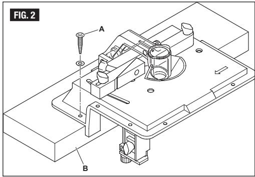
The SHAPER/Router TABLE comes assembled ready to mount on the workbench. After determining table location, predrill the bench using a 3,2mm diameter drill at the four mounting hole locations. Secure table to the bench using the 4 wood screws, and washers. (Included with the Shaper/Router Table.)
See Figure 2:
A 4 Wood Screws & Washers
B Use 50mm× 100mm as alternative mounting option
INSTALL ROTARY TOOL TO TABLE
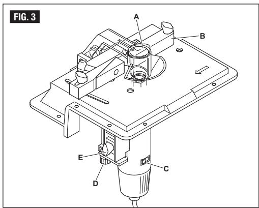
See Figure 3:
A Guard
B Fence
C On/off switch must face forward so left-to-right motion will turn tool off.
D Depth Adjustment Screw
E Clamp Knob
- Make sure the power cord of the rotary tool is unplugged and install the required router bit.
- Loosen the clamp knob and adjust the height of the tool holder to the lowest position.
- Move the rotary tool from the underside in the tool holder and turn the nut on top of the tool holder to fixate the rotary tool. Use the open end spanner to fasten the nut.
OPERATING INSTRUCTIONS
CHANGING ROUTER BITS
- Loosen the clamp knob and adjust the height of the tool holder to the lowest position.
- Rotate the rotary tool so the shaft lock button can be operated through an opening in the tool holder.
- Apply the shaft lock button and loosen the router bit.
- Remove the router bit through the table and install another router bit.
- Apply the shaft lock button and fixate the router bit.
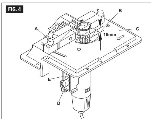
CUTTING DEPTH ADJUSTMENT
Loosen the clamp knob and turn the depth adjustment knob to set cutting depth. Depth of cut will be the amount the bit extends above the shaper/rodier table.
See Figure 4:
A Large Knob
B Depth of Cut
C Table
D Depth Adjustment Screw
E Tool Holder Assembly
Adjustment markings on the side of the tool holder facing outward are marked in inches and millimeters. View the markings prior to starting your project. Turn the depth adjustment knob to set desired depth. To ensure proper settings, rout and measure cut on scrap material.
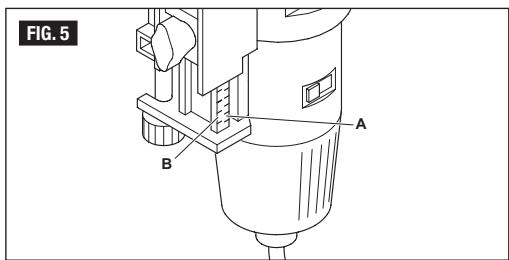
See Figure 5: Depth Adjustment Markings
A Inches in 1/8 inch increments
B Millimeters in 5 mm increments
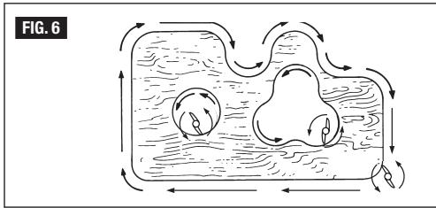
ROUTER FEED DIRECTION
The router spindle turns in an anticlockwise direction when viewed from above the table. For best control and quality of cut, feed the work into the bit in the direction that the bit will tend to pull the work to the fence. Feed the workpiece from right to left as shown.
See Figure 6
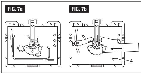
Feed direction is extremely important when using a pilot bit freehand on the edge of a workpiece as well as when using the fence with all bits.
See Figure 7a: Feed Direction without Fence
See Figure 7b: Feed Direction with Fence
A Feed Direction Arrow
Tips Table:
- Wrong Direction - Hard to control
- Feeding too fast - Overloads motor
- Dull bit - Overloads motor
- Cutting too large or deep in one pass - Overloads motor
- Feeding too slow - Leaves friction burns on work.
ROUTING USING THE FENCE
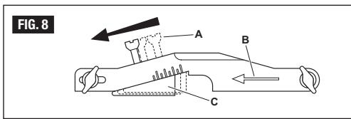
- Unplug the rotary tool before making any fence adjustments or bit changes. Feed the work against the rotation of the bit as shown. Most fence cutting is done with the support wedge adjusted to the right where it is in line with the fence.
See Figure 8: Fence
A Clamp Screw Nut
B Feed Direction
C Support Wedge
- Center cylinder of the guard can be adjusted up when making cuts using the fence. Loosen thumb nut, lift the cylinder up and secure by tightening thumb nut.
- When shaping small pieces or when finishing the cut on narrow, long pieces, use a push stick. Use 5 × 50 × 200 ~mm (metrics) piece of lumber notched as shown to make this push stick. It will enable you to keep your hands away from the cutting area.
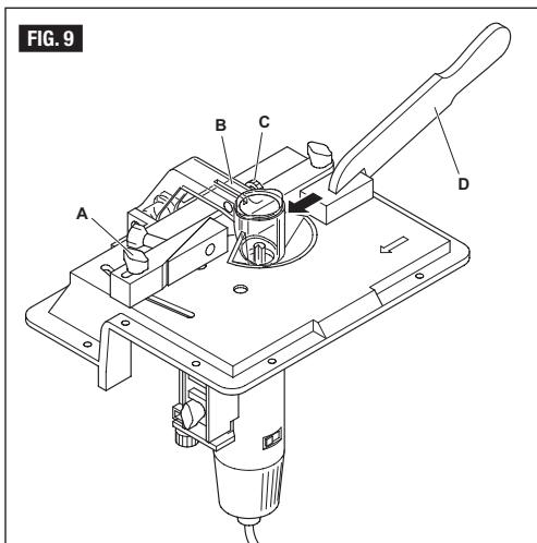
See Figure 9: Feed Direction for Straight Cuts with Fence
A Large Knob
B Center Cylinder
C Thumb Nut
D Push Stick
- To cut a straight groove, install the bit and set the depth of cut using the depth adjustment knob as shown in Fig. 4. Loosen large knob on left end of fence assembly to proper distance from bit to give desired groove location. Retighten large knob. Take a trial cut on scrap lumber to check depth and location of groove.
- When trimming the entire edge of a workpiece, adjust the support wedge for support of the workpiece on the left side of the cutter. First, adjust the fence to control the amount of cut. Take a trial cut of about 50~mm long and check the amount of cut. Turn rotary tool off. Loosen wedge clamp nut and slide wedge to left until wedge contacts workpiece. Retighten clamp nut to secure wedge to fence. Workpiece will not have support on both sides of the cutter. (See Fig. 8)

Place material between router bit or accessory and fence while routing or sanding edge.
ROUTING USING PILOT BITS
- When bits with pilots are to be used, move the fence back only enough to allow the amount of cut to be made. Keeping the fence close to the bits allows the fence to serve as a rear guard. In
special cases when the fence must be removed from the table, adjust the centre cylinder of the guard down to provide protection from revolving cutter.
- Only piloted bits can be used without the fence. The workpiece should be kept between the cutter and the operator, and fed from right to left.
- Feed the workpiece past the cutter without stopping and with a consistent speed, A change in feed or a dwell will cause an irregular cut.
EXPANDED TABLE WORK SURFACE
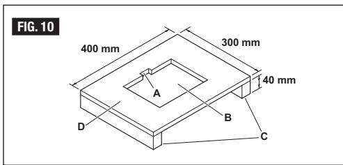
The Shaper/Router table is designed to make it easy to expand the size of the working surface. Use 10mm thick solid core plywood. Cut a rectangular hole in the plywood to fit over the table and secure using (8) #10 wood screws, 12mm in length. Support the table at both ends by securing 40mm high lumber supports to the plywood base. (See Fig. 10) (Hardware not included)
See Figure 10:
A 40 mm Slot to Clear Guard
B Rectangular Hole to fit over Table
C 40 mm High Supports on Both Ends will rest on Bench
D 10 mm Plywood
SERVICE AND WARRANTY
This DREMEL product is guaranteed in accordance with statutory/ country-specific regulations; damage due to normal wear and tear, overload or improper handling will be excluded from the guarantee.
In case of a complaint, send the tool undismantled together with proof of purchase to your dealer.
CONTACT DREMEL
For more information on the Dremel assortment, support and hotline, go to www.dremel.com
Dremel Europe, P.O. Box 3267, 4800 DG Breda, The Netherlands
Table de diagnostic:
SOLO PER I PAESI DELLA CE

FRESATURA CON USO DELLA GUIDA PARALLELA
FRAESNING MED JERN MED STYREHOVED
AAAATKOTTIKQN EAPTMATQN
- EeoiEiTe Tn laBn Tou oqiYknpa Kai puOjIoTe To uooc Tou ouTnIaTO OuyKpAtns TO EpyaleIOu OTN Katweptn Theon
- IepiopTejuTo TEpiopOkiOe pyaAei Toa Wte va mtpeiteva yeipioTeite To kolo apo aapaiAnic meaw evoc aoivajato sTo ouTtnja uoykpatanong Tou pyaAeiou.
- Kpatnate to kolapo aopaians kai yaapwote to kottiko εfaptnua.
4 Apaipote To KOTTIKO EApTnua Meaw Tou TpaTeJou KAI EYkataoTnEva aAlo KOTTIKO EApTnua. - Kpatnato To koIapao aopaiionc kai oipTe ToKOTTIKO EApTna.
PYOMIISHABOOYKONH
Aaakapete To ojoAo ouoqiyngs kai otpeyte To ojoAo pubuianc tou Baouc via va pubuiote To baoc kotn. To baooc konic evai n atoataan kata nTo vtoia pnoeexei To kottikr Tavw an tov Tlaaka diapppwoc/xaopaes.
_i_e to 4:
A BaOoKoTnC
B TpaTec
C Bida Puaions Baouc
D Suotma Suykpatnngs Epyaieou
E Meyann Aβn
Oi evdeieispuoians oia layia nts baans otpiinss tou epyaleiou, Tou tou Poc ta Eeuivai oneiuejeves oe ivtoes kai oe xiaioata. Deite Tc evdeieispriv Eekvihoetne tvp eyaia oac. Tpeye To poxlo puiians Tou baoaic va iu puaiaote To baoos Tou entioue. Via ia eiete Beboiot Oti ou pubioiaeic evai owotec, xapaete eva axnpato ulko ka etpnpote to baoctns toqnc.
AeTeTOx.5:EveEigic PoOmuGs Baoous
A IvToεs με 1/8 IvToa αιξησ
B XIAOToA 5XIAuEgnon
AIEYOYNsH TPOΦOΔOΣIAE PΓΑΛΕIoy XAPAEH
O afovaTou epyaleiou xapaqns otpeptai apioteopotpopa, otwic paiveita nauo atn TIVAIA. Fia kAUtepe EAEYxo KAI TOIOnta TNS KOTNt, TPOPOBHTOTE TO uALKO tTOKTIKKA tNI pOpa TNO TO KOTIKBO Ta TEVEI VA TPAJIeTo UAIKO TPOCS TO PTOATEUKIO NAEyMa TPOPOBHTOTE TO uALKO tAO Taejia TPOC T AIOPETA
_TE to 6
H dieuovan tropooosiaic evai onuavrikiotav xnpioitroie KOTTIKIOe TIAOTo Tou KIVEIaei To Xepi OTKV AOKN Tou Ulikou TPOC ETEEPyAia KAUBc KaTAtx npioitooite To TPOsATEUIKIO TEAYJU e ola To kOTTKA.
eto _X 7a:Kateuuvon Tpoosodios XwpiΦpaxn
e TE TO x.7b:KATEUuvon Tpoosooiac Me Ppaym
YKA3AHnI. Hecna3eaHemo Ha
onunacuhme no-dony ykaazahmu moxe da doeede do mokoe yap, noxap w/uni dpyeu mekku npaemu. Tepmuh'm "enekmpouHcmpyEmn" ce omhcdo zaxpaehau om enekmpueckama mpexa (c kaaben) enekmpouHcmpyEmnu.
IATA3ETE TE3N HNCTPYKUIN
PA50THO MRCTO
a. PdIbDkAITE pa6bTHTO C MRACTO N NOpeHeo BeNoporaBkbm U HeoccmmbHOno oceemnneue MoZam da peudzukammpydoou zononnyku.
6. He paBOTe T cEKeTPOHCTPymEnTH bBb B3PBOONaCHA cpDA, pNn HANHe NIEChO3AnAMM NTeHOCtN, rA3OBe nI npaxo0bpaHN MATEpAAIN. EneKpmOuHcmpyMeHMtme Moaam da oDcenm uCKpu, KOUMO Moa am da eB3nnAmHemr npaxoo0paHUM mamepuanu unu napu.
B.Дрыктыдаи истричимнидаану о entekртунструмэнто на Ваме на павота.Моглочаевая на Неманuarно може доedoюdoэдбадаю конрпюEbpxу entekртунструмэнма.
BE30NACHOCT IPN PABOTA C EJEKTPNUECKN TOK
a. ⅢeCenBt HA eNkTPOHnCTPUMHTA Tp6Ba DA cbTOBCTBA Ha H3N03BaHHa EeKTPnHeckn KOHTAK. B HmKaB cB syaHne POpMeHHe KONCTpyKUHTA Ha UIcENca. Korato p6OHTe CbC 3a3eMEHN (3aHyIeHN. EeKTPOnHCTPUMHTH He H3N03BaYte aADTepn 3a IeCNca. POn3eaHemHO npUauHaHn U cecnu U KOHAMKmu HAMnAEEpuCK oMokoe Yoap.
6. ɪəsərɪbʌtɪeɒnɪpə haɪrənto Bɪ nɔːdʒaʒæmɛnɪnɪnɪz aʒuŋhɛnɪn noBjpxHOctnɪ, hʌnp. trɒbɪ, padɪatənpɪr, neɪkɪnʌxədʒiNɪnɪ. Koəamə mənɒmo B u e aʒaʒæmɛnɪu zaʒuŋhɛnɪ, pʊckbʌm o Eʒ3HUKaBaHe n Mɑkɔe yɒdæ p eɪo-ʒɔfʌm.
B. Ppndna3aIe nektoPHNCHyMEnTA OT dbxdi HnBnAra. IpoHukBaHemHO bOa e enkmpouHcPymMeHa nouuaaa anochomca m okoae yad.
r. ⅢnON3aBte Kabe na cmo no npedHa3HneHHe. He nON3aTe Kabe na 3a Hocene Ha eneKToPOnHCTpyMeHa, 3a TereNe IIN 3a INBkDahe HA zuCenCe Na OKtKaT. IaTeze Kabe na OT harpBaHe, OmacraBaHe, OCTpn PsbOBe INI DInkseUc ce AactN. IoepeDenu unu ycKaHau KaBenu yEunuAam pucka m oMKo e yap.
Korato pa60TIne c eIekToPnHcTpymEnHa oTKpIto, n3no3BaIte cAmo yDblNkIeTNi Ka6BnI, npedHa3NaHeH 3a pa60Ta Ha oTKpO. I3no3BaHemo Ha yDblNkUmeI, npedHa3NaHeH 3a pa60Ma Ha omKpUmo, hAmalraa pucka om mokoe yOap.
f.Ako ce hana rnoon3baheTo ha eneKtpmnHcTpyMeHTa BbBnaxHa cpea, nnoon3aIte npdeanae npeKcb3a 3a yeTuHn TKOe. Hnnon3aHem o npdeanae npeKcb3a 3a yEmHu mokoeHAMamraea onachocmma om 6b3HukBe Ha mokoe yopd.
JIUHNI IPEIINCA3N CPEICTBA
a. b. Deiete BHIMATEHNI, CNEDETE BHIMATEHNO DEICTBMTA CN i pa60tete npedna3nBO c eENKTOPHNCTPymHTA. He nIOn3BaTte eneKTOPHNCTPymHTA, KORATO cTe YUMOPEN IIN NOD BHNJHnHO tA
HapKOTUHN BUECTBA, ANKOKON IIN yNOnBaUN NekpCTBA. Eduh Mue paceraeHcOm npu paBoma c enekmpouHcMpymema Moke da Ooede do cepo3UHn HaupanRBeHua.
6.

N3no3BaIe npedn3Ha ekmnpobka. HocTe BnHarn npedna3H OOhna.HocEhemo Ha noDxOduu npedna3Hu cpeCmea kamo duXamelaM hacka, 3dpaeu nIbMtHO aamOpeh CuS cMaBun apaFep obyku, amHouH Hamanba PcKsO om haparBHeHua.
B. ɪəsərbaɪte Bkɪnʊchætɪŋ Ho ᵋeɪntpɔmHCTpymænta no HæbHMænae. Iːpɛdɪ da Bkɪnʊhε Μινeçεπβa I bæpaHæbaʌtaɪmpexka ce yþeβepe, Ye nckobənɪt pnekbCsbæ E bɒnɒkθeHne "ɪkɪnʊhɛno". Ako npu hòcêne Ha eɪeɪkpouHcmpyemHa mɒþkʌmme npS cma Cu ɛs-pxv Ncskoʊraɪp NpksCsbæ unu ákɑ nɒðaʌame 3axpaHæbaʊn hapεşehue Ha eɪeɪkpouHcmpyemHa, Kɔəma e kɪnʊhɛe, 6b3Hk8a onaOHcscm om 3nɒnɒlɪya.
r.Ппдддддддддддддддддддддддддддддддддддддддддддддддддддддддддддддддддддддддддддддддддддддддддддддддддддд徴унчte eenktpnoHcTpymHTe oTcTpaHete BCNKn NOMOUNI HcTpyMENu RaeHNK KIOVObe oT Hero.TaeeH NIOU NOMOUn eHNCpMym,3abpeAoe 3akaeH naEpbmaCa ce YacUmHa eNekmprouncMpymMeMa MoKe O da npuHuH npaharBaHua.
H. He ce npotraite c ycnne. Pa6omeme e cmaunno nonojxue Ha maonocu cu nooobpkaime paoeohoece rpe3 anomoto epeme. Taka ue mojeme no-do6pe da konhpmnupame enekmpouhcnpymema, ako eb3hukne heoayaka humyauaia.
e. Hocete npdojmo so nekno. He pabomeme c wupoku dpexu unu 6kyma. Pzkmte kocama cu, dpxume u pbkaumcme cu na bezonacno paacsmouhne om ebpmau ce acmu. Wpokume dpexu, 6kyma unu dbnmu e kocu moam da ce zakayam om ebpmauime ce vacmu.
K. Ako ce npedbinkda 3n0n3BaHeto Ha acnnpaOnnHa ype6ba, ce ybepe, che T e BknoeHa n paobTn HpmaHNo. 3n0n3aHemO ha maKaea ype6da HamaIRea onacocmMa 3a 3dpaeeMo c8b3paHa c6c 3anpaauaHe.
3.He 6ba06TaBte a36ecToCbIbPkaU MaTePnAan (a36cTbTe KANePoeRHeN)
И. Ako BCNEICTBME Na H3BpBbAHATA DEHOC MOKeJa CEOTeIN BpeEN 3a 3dpABeN,NEChO3anAnIMn HnB3PbONoCN IN pax, PnpBAPrTeHNO 83MaJIte NOxOJauN npDnA3HmepKn (HrkOIO npXoBe c KaHcpeRoEHH);paOBeTete CdxNAeTIHa MACKa N, AKO e B3MOKHO, BKIOUeTe acnIPAuONHHa ype6Ba.
N3I0JI3BAHE IIOIIbPjxAHE HA EJEKTPOINHCTPYMEHTITE
a. He npetobapbaite enektpnohctpymenta. 3nnon3baite enektpnohctpymeta camo no HEBOTOpnpdHa3naHEnHe. Ipepaobumte no-do6pe u no-6e0anaccho, Kozamu 3nnon3aeme noxodma n enekmpouhcpmyem 8 aadadhenom npoa3o0dumra duana3oh Ha harno4abe.
6.He nIbnon3BaIte eNekTPOHNCTpyMEnT, NHTO yNcOB pNeKbCbae o nobpeDeH. EneKmpouHcPymEmn, KoIMo He MOnE da ce 6knOuea U u3KnOuea C npKbCaae e onaceH u mPraea da 6bde peMOHmuaPah.
B. Ⅲaedete ucnncena oKT kOHTA tnpaen da npabate Bcakbna hactpoikm, CMeHn ha npncnocnbneHH, Hn npbnpatae enktpoHCTPymentHa.Takuea npneNaHmupeku HamaIaeam pucka om EKIOUcheah Ha enekmpouHcnpyEmHa no HeBHumAue.
r. Korato He nIbn3BaTe eNekTPOHNCTpyMeTHa ro cBxpaHbAte N3bH o6cera Ha deuHa He No3BONBAITE Ha ImuHa H3eAn03HATn C eNekTPOHNCTpyMeTHa mNn C Teu HNCTpyKmua da pa6oTt C hero. EnekTPOHNCTpyMeHMume ca onachu e pbUeMe Ha Heo6yHu npome6umenu.
I. Naodp3xKaHa nEeKToHcPmEnHTe.IPOeBepTe 3a paaMeCTBaHETO HIN 3aTARHeTO Ha NODbHXNtC XACTn,OTyHEni YactH N BCYKn DpyN 6bCTOrTeCTBA, KONTO MOrAT Da BNIRHTA Ha paOToTaHa nEeKToHcPmEtHa.AKO e NOpBeDe,NonpaBete eEeKToHcPmEtHa npde Da no 3nON3BaTe.MHOe 3nONnyku ca npnuHEnu om Nooo bpxJauH eEeKToHcHpymEmHu.
e. Panaete pekeuimte nhtcypmeontcnn u cctmnpoepoe 0cepupepepepepepepepepepepepepepepepepepepepepepepepepepepepepepepepepepepepepepepepepepepepepepepepepepepepepepepepepepepepepepepepepepepepepepepepepepepepepepepepepepepepepepepepepepepepepepepepepepepepe pe
K. 3nO3BaIe enekTPOHCTPmEHTA, KOCHMATBInTE n KApKaHNIuTe KbM HrTo CNOpe Tc3N INCHTPyKuN i npEdNa3hauHeHTo HA OTdJIHnIA Tm EneKTOPIHCTPmEHTA, B3emaiKnIOB NHIMHHe YCNOBtHa Na pa60Ta N BIda pa60Ta, KOTo Tp8Ba Da ce NbBpSi. HnON3eAHemo Ha enekTPOUHCmpYMeHa 3a pa60Ma, pa3nNUH om Me3u, 3a KoMo e npedNa3hauHEn, Moaam Da odoebam do anochcmu.
3.Ии�нзаьгд.TССКИ ИМДугТРКУТСМЕТДЗАЗКAPБЕНУ NOIDPbXAHNE NA B60YBbPbY CTaBnHNA NpTФмDA.
n. ⅢποJI3BaIe cAmO opuINHaJIHn akceCoapN.
IIOIIPbJXKA
a. PemOHnTpaIte BaIIINe IeKTePOnHCTpyMeHT cAmO OT KAIANmIHpAH NPcOHaN 3MnON3BaU cAMo OpiINHAnHn Pe3epBn HActN.Toea ue Bu zapAHmua,ue ce 3ana38a 6eONachOcmma Ha eKeINpOuHcPmymHa.
YKA3AHNIA 3A BE3OПАСHA PABOTA C OБЕРФЕ3И
OBUUN
MaunHata He Tp6Ba Da ce 3n0n3Ba ot Iina pod 16 roinn.
- PprodиI3BpUBAHETOHaKAKBATOИДаБИЮНACTOPkaIIMCmHAHa npHnAdneXHOCTBnAHNi3BaXdaJIte UeNcEcnTe OHTAKTAHa ENEkTPO3aXpaHABHTo.
ДОпьЛНITEЛИн AKCECOAPN
I3No13BaeTcMoPnHaNDeXHCHN,NHrTODOnYCTMnCKOcT HbBpTeHe nIPOJLMAIMINa PBAHMaKCMImHATCkoPocHT Ha BbTpHe HnPb3eH XoHd ENEKTPOMHCTPYMHTA.
He 3n013BaIte NoBpeDEnH IJIe DeOpMpaHn Ppe3OBAuH NHOKOB.
- I3noI3BaIe cAmO ocTpri Ope3oBaun HOKOBe.
- Pana3eAkcecoapnteOydpnNcTpecenH.
IPEДИ YIOTPE6A
ИЗбгав trade Novpevi, KOITO MORAT DA 6bDat prnHINENI OT BHTOBTE, RTO3eN IN DpyTN MEtAHNI ENEMETN B op60BOTBAHNA detaII; OCTPahete N trpei da 3anoHHTe pa6Ota.
- PnB BkIOUbaHE B KOHTaTc, Ce yBepete, Ye NcHCTpyMeHTa e 13KIOUeH (NcHCTpyMEnTH C HOMHaTHO HAnpEKeHHe 230V mN 240V MoTa Da bDaT BkIOUeH N KbM 3axpaHbAe C HAnpEKeHMe 220V).
- PpaxbT OT HKON MATEpnni, KATO HAPPMMEc bIbPkaa OonoB 6o8, HKON BNOBE dIpbceHnA, MNEpaneH mMetan MoKeA da 6BeDeBPEN (KOHTAK IJN BIIuBaHe h TaKb PBAX MOrAT da npHnHrT aneprrnH peakunm nInn pecnipatopn H3abOyBAHN Ha opepatopn IJN CTsOHTe HabNIOo Nua); kON3BaaTe npTMOBnPaxBa MaKa n IpaobTe c aCnpnrpuao npxta yctpoCTBO, KORATO TAKOA MOKe Da 6Be Cb3pAO.
CnbadBaIe TeDeHINHPaHTe NO Bc3MckBaHNoT OTHOCHO 2aIpaHoeeDCTa 3aMaepHaNTNa, KOITOn Xenaeta Da o6ba6ToBaTe.
ПгнКIOИЧАБЕН BOKTAKA CE yBepETe, Ye eNEKTPOINHCTPyMENTa eN3KIOUHEN.
IPIN YIOTPEBA
Bnhar npbXte ka6ena daene oT DnHexeTe ce aactn.
- He IaON3BaIte IHNCTpyMENTa, KORATO e NOBpeHEn UHyp3T INI OCHOBHnT BLOK ( = npdeNa3eMexaHn3b); 3amraHaT My cneBa da Ce n3BpUOn t KBAmDInuPAnHO nIue.
IaHTPMAEeBnIpCTNTE CNOT Ppe3ObaaHIOK, KOrato HINCTPYMNTEA E BKNIOHEA.
B cnuyh ha enektpnecka JIN MEXAHmHa HEn3npABHOCT, NkHNOHTe He3a6abHO INCHPTyMeHTa N pKeBcHTe KOHTaC c enektpneckata MPeKa.
B cnuyaHa 3akmHbAhe Ha Hoxa, ppei3BnKbaIo Bn6paMn, He3a6abHO n3KlHOte NcHcTpymTa.
B cnuyai na npekcbaahe Na 3azaPbAbeHO nNn cnuyaiHo n3dbpBaHe Na 1eCenela H3a6abHb, BeDnHa n3KnIOHTe HnCTpyMeTA, 3a Da n36BerHete cnuyaiHO pectaptnpaHe Ha nHCTpyMNTA.
- Ppncnnpahe Ha nHCTpymEnTa, He npnnaaiTe cnna.
OKOJIHA CPEDA
BPAKYBAHE
C orneI ona3BaHe na OKoJIHATA cpeA enEKeTPOHNCTpyMEnbT, pONJbHInTeNIThe NpOncOBNeHn I noAKOBkATA TpRBeA da 6bDAT noNDIOxHe H naDIOXHa npePap60TKa 3a NOBtOPHO M3NO3Ba He Ca bDbKaUaTe CE B TRX CypOBHH.
CAMO 3A CTPAHNOT EC

He 3xBbPraTe eneKtpOnHcTpymEntte np6bntoBe OTnabu!
Cytlancho DimeKtmbata ha NC 2002/96/EC OHtocho 6pkaByhnh enektpknncn n enektponnn yctpnctbn
YbBpXdABaHeTo KATO HauNoHAnen 3aKOn EneKTpOnHcTpyMeHTte, KOtTO He MOrAT Da CE hN0n3BaT NOBeYE, TpRbA da Ce Cb6paT oTEnIHO nDaBat NDnAraHn HnNOxDpaIa NpepabOTka 3a OONO3TOBpArBaHE NaCbDpaXaunITE Ce TBx BTOPuHHc CypOBHn.
YKA3AHNIA 3A PABOTA
- I3noI3BaIte cAmO nOxOJaIe Ope3OBAIe HOXOB.
3aФрзованHa npofoiin,ycnpoeHnHa strPnHnHnKpaHa p6aTOHm MaTePnAn,ImnoIaBaeIe HnPaPnBaUaBau Btynka. - Pridna3aBte CE ot eFekTTE OT N6bpaUHNTe, KATO NOdIbXpATE INCTpyMEnTa HnKecceapnte My, na3Te pBuTe CN ToTIIN U OraHNsPATE BauNtE MoDENHa paObaTa.
CTIIOBAHE
ПИСТАВКА 3A ИЗПОЛЗВАЕС ΦЕР3A DREМEL, MОДЕЛIM 300, 395, 398, 400, 4000.
BHUMAHNE: Ipnoyetete BHMMATENO UIIOTO pBKOBOCTBO C HNCTPQUN, npEdu nA hINON3BAte Bauata npOPOHnfa Ppe3a/ o6epe3a Dremel. 3anaete nHcTpyKunite 3a b6Dneu cnpabkn. Ta3n npictabkA ue npBbPhe BpTAAuca ne HcTpymEnh Ha Dremel B maca 3a npOPOHnHa Ppe3a/O6epe3a 3a oOpOMHe Ha p6oBe, npOPOHnPaHe, INdbIb5BaHe A Kne6oBe, faoCoHHaPe, 3aqrAnJaHe Ha Pb6oBe, CseDInHBAHe n T.H.
BuxTe pfurpa 1:
A OchoBa
B Ankepen 6oNT
C DbpxkateNHaHnctpyMeHTa
D TOnMa pBkoXBaTka
E BnHT 3a HacTPOkHa Ha bIbOuHnHa
F Taika-KBaDpaTHa
G Cko6a 3a dIbIbOuHaTa
H BnHT 3a CkO6bTa
I Panae
J MOHTAXEH BnHT
K Kpunuata raika
L IpoTeKTop
M Myda
N Taika 3a 3akpenBaun60nT
0 1a#6a #9
P 1a6a4.8 MM
Q OrpaHnHTen
BnHT 3a KJIINHOuHaTa CkO6a
S KINH
MOHTIPAHE HA MACATA KbM PABOTHNTE3ΓX
MACATA 3A IPOΦHIIHA ΦPE3A/OBEPΦPE3A ce npednara crno6ha n roTOBA 3a MOHTIPAHE KbM paOToTHNe TepXc. CneI KaTO onpeDInTe MEcTOnIOJKeHnE To, npoBnIE Na CBtoETNHTE MeCTa B Te3Rxa YeTIpNTMOHTKHNOTOpBa c DnAmetb3,2 MM. 3aKpEnTe Macata KbM TE3RA Xpe34-Te BVtHa 3a Ibpo R uWbEit. (BKnOyuHn B KOMPNeKTa Ha macTa 3a npoФHIIa Fpe3a/OBepΦpe3a.)
BuxTe durnypa 2:
A 4dbpBeHN BnHTa Nwa6n
B IN3NO3BAITE 50 MM x 100 MM KATO anTEpHATMBNA OONIa 3a MOHTAK
MOHTIPAHE HA BbPTaUNCe IHCTPYMEHT KbM MACATA
BuxTe pfHypa 3:
A IpoTeKTop
B OrpaHnHTen
C LyKOBaHIN pRbCbAayB6Ba aEo6bPnHaHnepd, TAKA eD BIXHEKHETOOTARBO HADCHOa DaIK3NIOVAH NHCPTMHTA.
D BnHT 3a HactpoKa Ha DbIbOuHnHaTa
E Bbptraa pbkoxBatka 3a CTnckata
- Ybepete Ce, Ye 3azaPanhBaunrKabEn Ha bBpTnIe CE HcTpyMeHt e NkIIOuYeOHTaKa, I NOCTABeTe Heo6XoDMMnФpe3OBAuaN NaKapmIKN.
- Paxna6eBbptraata ce pkoXbaTka n peryInpaaTe BmOuHnata Ha nbPxaTeJHa HnCTpyMeNTa Ha Hn-HNcKO nIOJOKeHMe.
- PπdBxke Te BpTnμe CE nHCTpyMeHT KbM DoHATA CtpHa Ha DxbkataRe Na HcTpyMeHT N 3aBbPteTe raiKATA OT roPHTa My cTpaHa, 3a da ro fKnCnPate. N3nON3BaIte OTE bOpEn raeuH kNIOU, 3a da 3aterHeTe raiKATA.
MHCTPYKLIMN 3A PABOTA
CMRAHA HA ΦPE3OBAUITE HAKPAHNI
- PaxnaabeTe BpTaIaTa ce bpKoXBaTka n peYnImpaIte BmCOyHATA na DpbKaTeIa Ha IHCTpyMeHTa Ha Na Hn-HNCKOT NOJOKHe.
- 3aBbptete BbPTaunu Ce IHCTPMeHT, Taka Ye Da IMATE doctbI Do boknpaHTo Ha MydaT ape3 HAKO OT OTBpHTe Ha DbPKatEra HA IHCTPMeHTa.
- 7aEcbTae6bKpAeHTo HMaMyFaTa nPaXHa6TeF pE30BauaHae KauHnHKn.
- Cbane ro, kato ro npekapate npes macata, noctabete npyr.
- 3a#eHCTBaIeBIOKIPAHETo HA MypTaIa 3aTeHETe HOBNy fpeO8aUHnA HauKpHnK.
PEGYUNPAHE HA DbJIbOuHATA HA PRA3AHE
Pa3xna6eTe pkoKbATkata Ha CTNcKa I 3aBpTe TBe BpTnAca Te pKoKbATka 3a pepynIpaHae Na IbIoOchHATA, 3a da 3aadadete DblOocHATA ha p3aHe. Ta 5e bIbe paBaHa Ha pa3ctOHeMeTo, H KaETO hApaiNkbT ce n3daba Ha nPocmHata Ppe3a/ o6eppe3a.
BuxTe pfHypa 4:
A TOnMa pBkoXBaTka
B Dbl60uHa Ha cpe3a
C Maca
D BnHT 3a HacTPOKa Ha DbIbOuHnHaTa
E MoHTnpaHe Ha dBpxkATEJHa HnCTpyMeHtA
MapkePte 3a peryInpaNE O TbHnHaTc Tpna H TaBpKATEHa H nHCTpyMeNTa ca pa3rapeDHeN B mHIOmeTpR. Pa3rIeJaTe r, pneDi da 3aOnOHTe paOta. 3aBpTeTe peryNatopa Ha nbIbOchNuHATA, 3a Da 3aJaTeTe Heo6xOIMMaT A cHIOCT. 3a Da cn rapAANTpate npabuHnH NactpoKn, HanpabeTe pa3e3 B naphe 6paKaYBaH MATEpMa I nTo h3MepTe.
BnKTe pfrypa 5:Mapkepn 3a perynpane na DbIbOuHnata
A INHOBHe HA CTbIKNOT 1/8 HnHa
B MnImMeTpna CtbPkNOT 5 MM
IIOKKA HA IIOJABAHKbM OSEPΦPE3ATA
IIINHnEHTb HA o6ePdpe3a Ce BbTn B nOcKa, 6oPaTHa HA cauoBnKOBATA CTpeKNA pI NOrPe3 KbM Macata OTrope. 3a HaNIOB6pn pe3yITATn I KauCtBO H aOeNpO NaDaBae TeteAIna KbM hKnapAHHa B NocOKATA, B KTOrO HApKaiNkBTc Se CTpeMa Da N3bYtaB tEtAIna KbM OrpAnuHTeTna. NOpBaAte DetAina OTnRABO HAdrCHO, KAKTo E nOkazao.
BuxTeΦnrgpa6
IIOKoKaTa H a NpOlaBa e H 3NkOuHTeNHO BaoJn pRiN3N3BaHa NE hAkapaHNI K bOaay Cb cBcOboND bDmKeHne N pRb6a H aTeaHna, KaIKTo N prn I3N3BaH e O rpaHInTEnE 8CNCHApaknHnIe.
Bixte pfpya 7: Iocoka ha nodaBahe 6e3 orpaHnHTen
BixkTe fIgura 7b: Iocoka Ha noDaBaHe c orpaHmHTen
A Ctpenka 3a nocokata Ha nodaabaHe
TaBnua cbc CbBetn:
- Henpabinlha nocoka - trpydno ynpabnene
- Пекално 6bp30 noDABaHe -претоварBAHe Ha MToTopa
3.ИЗтбпен НакраинК -претоварыноу MTOPA
4.Ппекалношпрокилдьбokр ряза He 3a einn xoI -петоваране на мотopa - Ппекално бавно поаванe - no pa6obTHЯ дайл OCTabat cneiOT ИЗгарянe.
BnKTe pfHrypa 8: OpranHmTeI
A Taika 3a 3akpenBaunr 60nt
B Iocoka hanaodaabahe
C OnopeH KInH
- LcHTnpaunrTzINHbPHa nPoTeKTopoMoKe Da bDe perynpanDorropHO NOJoxHepe npnI3BpUbahe Ha cpe08e CnIOI3BaHa HOrpaHInTePa. Pa3XlaBeTe KpNlTaTa Raika, nobdHReTe ZINHbPa harope I ro 3akpenete, KaTo aTeHete KpNlHaTata raika.
3.ПиOB6a60TkaHaMaKINDeTaIIMnHInPn3aBbPbBaHeHa pape3aHaTBKnNnBbPnDeTaIIMn,3nON3BaIe nPbNkHa 3a N6yTbAte.3a HApPabataHa TakabaNpBcKaN3nON3BaIe Naphe DpbOcPa3mepn5x50x200MMcnppe3n,KakToeNOKa3Ao. TaIe BNnO3BOni DaBpXKe PBcTe CNdaleeOT3oHATA Ha pra3aHe.
BnKTe pfIgura 9: Pocka Ha noIaBaHe 3a npaBn cpe3Obe npn HnOJI3BaHe Ha orpaHnHTeI
A TOnMa pBkoXBaTka
B LcHTnpaUuJINHdbp
C Kpniluata raika
D Ipbka3a n36yTbahe
- 3a da m3pekete npab jxne6, MOHTnpai Te hakpainHnka n 3aadaite db60hnhata ha pr3ahe c NOMOHTa ha pkoxbatkata 3a perynipha Hdb60hnhata, kAKTO e NOK3AHO Ha qnr. 4. PaXnaIabeTe roJmATA pkoXBtKaT O JEBN Kpa H b6nKa Ha orapHnTEnIa, 3a da 3aadaeTe npoXdoJIaTO paoCTOnHNe O T hakpainHnka Do JxelAnO To MeCToONIOKeHne H xne6a. 3aterHeTe
OTHOBO rOJMAHATA pKoXaBaTka. HnapBabe np06eH cpe3 bpyx 6bpaYbaHO nape De bpo, 3a da npOBepITE dIbIoOCHNAta n paONIOJKeHNTo Na ce3a.
5. Pn6ob4o7ka Ha cenpyb6 ha daen Detan, perynipate OnpnHn KInH, TaKa ye Da ndoBpXpa6oTHnaTeaIOn IybaTa CtpHa Hoka. IIpb8o perynipate OrpanHnTeta, Taka ye Da npraNBA RoLEMNHTA Ha cpeA. HanpaBete np6eB cpeC dblnxHa OKJIO 50 MM n npOBepeTe roLEMNHTa My. IVkNHOte BpTRIaJe Ce IHCTpyMent. Pa3xNaBeTe raiKa tHa KNHObUNHa TcK6a N pIb3HeTe KNHa HAnBO, DOkATO BNE3e B KOtAKT C pa6oTHnTae TdA. 3aterHete OTHO BO rKaHa t KaC6bTa, 3a da 3akpeniTE KInHa KbM OrpanHnTeta. Pa6oTHnT aetAI HAma da NmMa onOPa ONDeTcPAn Ha HOKa. (BnkTe qR. 8)
BHIMAHNE
IocTabete MATEPnala Mzkyu HakpaHnkaHJIN akcecoapa Ha o6epfpe3aTn
OrpauHHTenI,doKATO npoOpHnnpate Hn 3aHnXdape pb6a.
IPOΦNIIIPAHE C N3IOJI3BAHE HA BOJEUHAKPAHNI
- Korato Tpr6Ba da ce M3No7Bat NaKapaiHnui C BODaH, prinDBeKHTe ORAPAHNTEIN H3ad Camo Do no NOXKeHne, npi KoTe Da MoKE da CE HanpAiB CbOTBETNHT Cpe3. PnpiDbPxAHeTo Ha ORAPAHNTE BnI3O do NaKapaiHnui Me No3BOJIaBA da CNYkx KATO 3aDen pnoTKeTOp. PnH NcKOn CneUaHm CnyAun, Korato ORAPAHNTEIT TRp6Ba da 6bde CaneH O MTacAta, peryPiNaTi Te CEHTpRpaAun CInHbPn NaTPOeTOp BdoNO nONoXeHne, 3a Da OCSrpynte 3aunita PnB5BpArTHO DBoHNQHe H aHOxa.
- Camo hakpaiHHuHTE C BODaY MoRAT Da CE IINON3BAT 6e3 orpaHHTeIa. PaobTHnA T deAnI TprBa da Ce HAMpu MeKdy HOKA n OpePATOPa H da Ce NDaba OT DAHO HANBO.
- NpOABaJIte paoBTHnA DetAI BbB HOKHa 6e3 Da cINAPate n C NOCTOARHnA KcOPOCT, PpOMA Hn BaHnA Ha NpOBAHe IINI ppeKbCBAHae Ue DOBeDE O HePAHEB cPee.
PA60THA NOBbPXHOCT HA PA3TErHATATA MACA
Macata 3a npofoiHna pfpe3a/obepfpe3a e c3daedha 3a yneChbaHe na ybeyniHaBaeHTo na p3aMeRa na paoBtHa nata NobpXHOCT.
VnO3BaAe TBpD nIepeNpTa C de6eHina 10 MM.N3peKTe B Hero npab0BfJbn OTbP, KOIto Da OTTOBpaH na Macata, n O 3akpeNte C NOMOua Ta (8) BVNTOBe 3a DpbBo #10 C dljnxHn 12 MM.OcHpyrE tone ONOp a DTbA kPaH na Macata, KATO noctabite dpBHeHn onopn b CMBOHn 40 MM na UneepnTatobata OCHOBa. (BVxTe fHr.10) (MATEpHnATNE He ca BKNHOeHN b KomPiKeTA)
BnKTe pfIgura 10:
A 40-MnIMMeTPOB npouen 3a nouchTaBe Ha npoTeKTopa
B IpaBoBfJIeH OTBOP, KOITTO Tp6Ba Da CbBnAdHe C macaTa
C Onopitc BncooHna 40 MM no Dbata p6a ue 6bDat nocabehn H aTe3Rkxa
D 10 MM wnepeppnat
CEPBn3HOOBcNJyXBAHEI TAPAHU
3aTo3 npDuykHT Ha DREML CE npedocTabra napHcBcIhaco 3akOHOBITE cNeMzHnHs 3a CbTeBHNTa cTpHa pA3nOpEbn; rapauHcIgTA uKTHOVA NBpeRd, nOeNt O M3HOCAbe B HopMaHINr XoH daPabot, oT npetOBaPBeHne HnHepaBInH yOntp6ea.
BcnyaHa peKnamaun,3npatete HNCTpymehTa Hpea3rno6eH 3aeNo cdokymeHT, yODCTBepRaau nokyntata Ha Baunra TbproBeu.
3A KOHTAKTNC DREML
3a noBee HnΦopMaJH 3a aocptmEHTa, nOdpbXkata n pRka TelefoHnBaPb3ka c DREML, nocetete www.dremel.com
Dremel Europe, P.O. Box 3267, 4800 DG Breda, HinderpaanJa
ALTALANOS BIZTONSAGI ELOIRASOK

A FIGYELEM
OLVASSA EL AZ OSSZES
AZ ASZTAL FELSZERELESE A MUNKAPADRA
CITITI TOATE INSTRUCTIUNILE.
Nerespectarea instructiunior
enumerate in celee ce urmeaza poate duce la electrocutare, incendiu si/ sau ranirige grave. Termenul de scula electrica folosit in continuare se refera la scule electrice alimentate de la retea (cu cablu de alimentare) si le celee cu accumulator (fara cablu de alimentare).
PASTRATI IN BUNE CONDITII PREZENTELE INSTRUCTIUNI
LOCUL DE MUNCA
OBLUME ITPABMITA TEXHMK M E3OTACHOCTI


BHIMAHME
IPOUHTNTE BCE INHCTPYKLIIM.
Ouubku, donyueHenbIe npu
bIIOJIHHeU npueeBHeHbIX Hxue UHCmpyKu, Mozym bI3aMtb
npaeKHe 3nEkpueCkum mOkom, noKap u/Unu npueeCmK
mKeJbIM npaBmAM. IcNoJIbOeAHnE Hxue NoHmue
<3nEkpUcHpMcyMe> pacnOpcmpaHaemc H a3nEkpUcHpCmyEm
c nImaHuem Otn Cemu (C kAbenem numHaun Otn 3nEkpocemu).
COXPAHNTE DAHHYIO NHCTPYKUNIO
PABOYEE MECTO
a. Pa6oHe MeCTO CnEyET COeDPKaTb YHcTOTe N nopRKe. BeCnOPrOkHa pa6oYem MeCeM u e0 nIHOxO cOseUeHue MOzym pueeCMu K HeucactnMb CnuaHae
b. 3aNepeiaeTcN bON 30aBtBcN 3NeKTPOnHCTpyMeNTAMn BO B3pIbBOOIAChNO cPene, B KTOPONI HxADITcR BCONlameHIOUceCe JXIDKCTN, rA3bl NIN nbIbN. 3NeKPTOpHcMpYMeHbMn UCKpRm, YMO MOJem npueecmNU K BCONlameHEHIOu nbIu unu napo8.
c. Pnirpaobote cneKtPOVHCTPYMHTOM He noJyCKaJIe 6bN3KO deten noctoPONHHnIu. Ppu oBmEHeHu 8o epMa paOboMb MOHO NOpepMb KOHIpoNBo HAD uHcMpYEmHMOn.
3JIKTP0B3O1ACHOCTb
He Bb6paBaiTe 3nEeKTPoHnHCTpyMeHTb I KOMMyHaJIbHbI MycOPII!
Cronhaco EAponeoncki DApneKtbe 2002/9/E3c o 3apstix 3nEkpTceXeCKN 3nEkpTOnbHxN hctyPmentax npi6Bopax,
a TAKKE O pNTBOPEOHN 3T0I DNEKPTBbI B H AUNHOAHBHe I PABO, OTCNYKBMBBE CNO BCPOK 3NKTPOHNCTPymTeBt HOITKNbI OTDeBNBO COOBATCn C JDABATCBn HA KOJONTHeCKN CTHYQ ToYTNNA3HIO.
COBETbI IO NCIOJIb3OBAHnIO
CEPBNCI TAPAHNTNUHOE OBCJNYXUBAHNE
RapantmHoe 6cbnyKbAHme npdykun KOMnHIM DREML OcyeCTBnTETCB A COOTBETCTBN C DEyCTBYOuMM MECTbIMnpabOBbHm HOPMAM. RapantHe naPocpTaRaETCA Ha Detanl, NOpBeRjHKHeIe cTeCTBENHOY m3HOCy. B CyNae nCnObl3oAHNAHCTpyMeHTaHaNaHcHnro rapantna TepreT cnly.
Ipaekpamaun OTCbIaIte HnctpyMeHT c6bpeBaewemy dnilepy, npinoxmb Yck, yDocToBepiauon nokynk.
KOHTAKTbIC DREMEL
ДононHTeNBHЯ NHФОмuaиб O6 accoTUMHeTe npOdyuKmDreMel, noDdERkKa nObIb3OBaTeNeI n RopUyA nIHHa HaxOJaTcHa caTte www.dremel.com
Dremel Europe, P.O. Box 3267, 4800 DG Breda, the Netherlands
ÜLDISED OHUTUS.JUHISED

ATETEVAATUST
LUGEGE LABI KOK JUHISED. Järgnevate ohutusnouete
HOIDKE KÖIK JUHISED HOOLIKALT ALLES
TÖOPIRKOND
UKSNES ELI LIKMESRIIKIDELE

PRIJUNKITE BESISUKANTI [RANK] PRI E STALO
Zr.3 pav.:
A Apsauga
B Kreiptuvas
C ljungimo/ijzungimo mygtukas turi butu nukreiptas j prieki, kad judesiu iis kaires j desine butu ijungtas jrankis.
D Gylio regulavimo verzle
E Spaustuvo galvute
A Inci in 1/8 incne difference
B Millimetre in 5mm difference
SMER REZKANJA
Os rezkalnika se vrti v nasprotni smeri urinege kazalca ce gledamo od zgoraj. Za najboljs nadzor in kvaliteto reza, rezkajte v smeri tako, da bo rezkalo vlekko predmet k ograji. Predmet obdelave rezkajte z desne proti levi kakor je prikazano.
Glej Sliko 6
KOPINTHEHEI ODPXABAHCE CHAXHOF AJIATA
a. Hemojte fopcnpatn chaxhni anat. Kopnchtte odrobajy hnh chaxhni anat notpe6ah 3a bauy daty cttyauniy. Odoepaayjum chaxHm anamom ypaudhe me nocao boje u cuzyphjye cknady ca Ibe08OM HAMEOHM.
b. HemoJTe KOpCtHTn ChaKHN anat AOK npeKnau CH on/off He padi. Buno Koju ChaKHu anam Koju He MOKE da Ce KOHmpOnuue NMOHY npekUOHaJe no Iacah U mOpa da ce nnonpae.
C. IVCKByuHTe yTuKau 13 M3BOPa cTpyJe npe BpuEHa bIIO KaBHX nOdeUbaHbA, 3aMHe np6oBa mN Ondaraba ChakHor anata. Taepe nepeHmBuHBe 636bdHcne Mepe CmaByjy pu3k od HeHAMepHOZ kTyBuHaBa ChakHOz anama.
d. ChaknH anat koJH ne yNontpebIaBate dpKHTe I3AHn Domauaja Deue H MHOJIte Do3OBUNTH da anatom pykJy ocObe KoJE HcNy OYNo3ate ca bHM INN OBIM yNUTCTBM. Chakhu anamu cy onachu y pykama KOpuchka KOU HUCy obyuHc.
e. Odkabajre Chakhe anate. Pboeperte da ny ci nu cnoj hn nni nokpetnhi denobin dojopeehn, kao Ito da ny ci denobynu yncipabHom taBny u CBE DPyre ycnobe Kojb 6bn MOrnn Da TYMH na pykoabahe chaknhm anatom.Ako je anat outehen, daje ra ha nonpankby pne nohohe YnOprefe.Y3pOK MHOeux Hecpeha je noo edopkaaahbe chakhoe anama.
f.Anat 3a ceYebe dApKTe OUTPMn HcCTMm.PpAsunHO odPjkBaah anam 3a ceYeBe ca oUmpum UeMaHa 3a ceYebe peJe Ce 3a2aAebjye u Nakwe aa je KoHmpnAmuCama.
g. Koprntte Chakn anat, np6bOp n 6tObe anata y cKnady ca OBMM yNytCTBMA n Ha NaHmKoJ je npeDbHEn 3a OpeHeny BpCTy ChakHOr anata yzmajyH y oBn4pAne yCnoBe n nocoA KoJ npeBa da ce obaBn. Ynomp6Ba ChakHoe anama 3a noCnooe KoJu Hucy npdeBuHenu MoKe da npoy3pOkye hacmahak onache cumyauej.
h. yntpe6ite cnojHnue nIi npyTn npaTmuaH naHH 3a noDynpahe obaPkaHa HcStbHIOJ nIaTfOpMn.
i. KopnCTnte camo opinnnaHnn np6op.
CEPBNC
a. Heka Baish Chaknhi Anat cepBicnpa KbanDipKOBAn cepBncp y3 Kopinhe camo nndentHmNxpe3epBNx denoHa. Ha maj nuhun o63eduhe ce opkaaee bcuyphocnu chakno anama.
YIYTCTBA 3A BE3BEDAH PAD CA IJIOJAJNUCOM
ONIHTA
Obaj anat He tpe6a da Kopncte oc6e nocn 16 roynha.
- O6abE3HO NCKONHajte anat n3 eJelKTPNHye YTMNHue pne Hero wTO N3BpUHTe 6nlo KAKBa INoDeuabaHa HINI ZAMEny pnp6oba.
PIMBOP
Kopmtte cmo np60b npja je do3boBena 6p3nHa y hajmaHy pyky jejHaka hajbehoj 6bp3HH npnpa3hOM xOdy eEeKTPuHOr anata.
Hemojte da Kopncntte oWteheHa nn deOpmcana rnoana.
Kopncnte cmo ootpa rloana.
3aHTnTne np6op od noTpeca, yapa n Macnix nobpunha.
IPIE YIOTPE6
I36eraaajte outheheha oupafobaa,ekepa ndpynx npedmeta H aBaAem noDpyjy pada; yknOHTe IX npe Hero 70o 3anoHHeTe pad.
YBek npoBeBaJaTe da nIe c HanoH cTpyje noknana ca HanoHOM habeEHm Ha cAmO anaty (aIaNHa KOJMa je habeEH HANOH od 230B mN 240B mya da pae i na 220B).
Ipaunha od mataepmjana, kao 10 cy 6oja koja caqpnx noop, Heke Bpcte dpBeta, MInhepani n Metal, Moke biNOnaCha (doDnir npYdnacbe paunahmeMo pOpyskoPbATn aleprinjcpeaekuJe n/Inn pecnipatopna oboBeHa pyKBOaOa nImu y 6bn3Hn); Hocntte Macky npotnb paunihne n padnte y3 ykbTyehnyej3a ekctpaekuiy npauhine kaada paadite Ha MeCTIma rde jy je Morythe npkBrHyntn.
- Пратуни поочи вазаши Кожа спрашим дрлдам рогиноком рада на образи ваним матерійамma.
- Поверпге дул щаел Икъун Када ra пикогчавateу ytuynu.
TOKOM YIOTPEBE
- Ybek dpxknte ka6n daneko od nokpTeHnx deNoBa.
Hnkaada Hmojte da Koprmtite anat ako je outhetahen Ka6bn ninn OCHOBHa nIOUa ( = 3aunTHmexAHn3am); 3aMeHy mOp a da oabn CTpyuHO nIe. - Ppcte n pyke npknte noaabe od rnoana ka ja e anat ykbuyen.
YcnyajdaNo deo He oEKNKTHOF NIM MEXHAHKHOF KBApa,OMMAX NCKbTywite anat NaN CKNHOJrTa rN YTHMNAe.
Ycnyajy da ce Itoanado 6nokipra,sto pe3yntpra Tpa3aem anata, OdmaX ra IckbYpHTe.
Y cnyaujya da dohe da no Hectanka stpyje nnn kko ce Kabn cnyajho NcKoJIH, OmaXk NKbUyHte anat, da bncte cnpeuHn noHOBHO KHeOHTOponlCAHO YkbUyBaHae.
Hemojte MHOgo da nprrnckate enektpnna anat da he 6n doJno do npectanka pada.
OKOJIINHA
OJIaIaIaIbE
Anat, np6op n am6anaxy tpe6an 6n copnpatn 3a ekonoikn noobhny peuiknaxy.
CAMO 3A 3EMJbE EY

He 6aajte ChaJHn anat y kyHNO cmehe!
YCKnady ca EbpocckOM dpeKTHOBm 2002/96/EC o OTnady
O neEeKInpUne H eNekTPOHnKOp OEnpE n HeNe pImMeye
CKnady ca HaauHOAHIN MzOHOM, eNekTpHNn AnATn
KoJIbMa je IcTeKao Bek TpaJaBHa MoPajy da Ce KynIbajy
OdoJeHo n OndaKy Ha ekONOuKn CnpBaHn NaHH.
CABETN 3A ПИМЕну
Kopuncte odrobabajha rnojana.
3a IrodaheBne OoRbHnaIparaneNHexCa 6OhoMCTPAHOH pIeMDTae konj cO6aPjye, KOpNCITE BoDnIuC.
3aHTITTE CE oN oNcNEiua Bn6pauija OndpKaaBHeM aIATKe I HeHnx HactabKa, OndpKaebajyH Baue pyke ToTlIMM I opraHINOBaHEM Bauxx paadHx obpa3a.
MOHTAKA
JOIDATAK 3A YIOTPE6Y CA MODEJIIMA DREML POTAUNOHJ AJATA 300,395,398,400,4000.
PAXHBa: Pankbno npouhtajre ueo yntcTb 3a pae npe ynotpe6be bauer Dremel cTOna obnikobau/roanuie. Cauybaje yntcTb 3a KaCNjuy yntop6by. Oabdoatak npetBorpHne Dremel potaunohn anat y cTo obnikobau/roanuie 3a Obnikobae Hnuza, roanhae, rpaBnape, obnikobaahe, neuapaehe, cnajahe NTd.
Budetcnkky1:
A NoctoBe
B Hocehni 3aBpTaH
C Dpkaa anata
D BéniKo dyrme
E 3aBPTaH 3a noDeuBaHe du6nHe
F Habptka -yETBpTaCTa
G Dpkaa dy6nHe
H Iotnnpn 3aBpTaB
I Ynoda
J MoHTaXHH 3aBPTaH
K KpJInn 3aBpaH
L 3aunntta
M Pykaba
N HabptKa cTe3HOr 3aBpTbA
0 3aNTnBHa noDnloka #9
P 3aNTnBHa nOdNoWka 4,8 MM
Q TpaHnUHnK
Klnnactn cnojHn 3aBpTaB
S KINH
MOHTAXA CTOJA HA PAADHY KJYIYY
CTO OBJIKKOBAA/ΓIΩDAJIANIUE nCnOpuyye ce CkNOnbEn h roToB 3a MoHTAKy Ha naDHy Knyu. HakoOn odpehYBaHa NokAuaJIe cTOnla N3bUaTIte pyne Ha knyni 6byjMm npEynHka 3,2 MM Ha eTnpri NOKaJIe. PInpArCTe CTO ha knyni KoprOCTe 4 aBptHa 3a Dbo N 3aTINBHe NIOLOUKE. (YKByueHo ca CTOnOM obJIKOBAA/rrOdaJIANIe.)
Budetcnk2:
A 4 3aBpTbTa 3a DpBO & 3aTnBHe nDnOwke
B KopnCTMe 50 MM x 100 MM KAO antepHAnBHy MoryhHOCT MOHTAKE
INHCTAJINIITEPOTAUHOHAIAT HA CTO
Budetcnkky3:
C 3aWNTa
D rpaHnHnK
E PteKmuaon/off(ykb/nckb) mopa da 6ybe OKepyHnape TaKa Da ce nomepaemb cBeA npema deCHO anat NcKbuyu.
F 3aBpTaH 3a noeWabAbe dy6nHe
G Cnojho Dyme
- YbePte Ce da je HanojHn Ka6I NCKbUyeH n INCTaMnITe notpe6Hn 6nt rnoaJIne.
- Ocnoobnnte cnojno duyme n noceinte BncnHy dpkaa anata ha hajnknn noonkaj.
3.Померпгетаразими anat ca doныстраху джач anata n OKерпгета habркн на врху джача anata kakсу босте уврстпгп разими anat.Корспгета кьчс са отвороним краяем за ппгиздам habрък.
YNYTCTBO 3A PAI
3AMEHA BINTOBA IIOJADJNUE
- Osoobodite cnojho dymre n nodecite BnCnHy dpKnaa anata ha hajnKnx noonKa;
-
3apotnpajte potaouHOH anat ka do bpabom hactabka moke da ce ynpabba kpo3 OTbOp Ha dpxayy anata.
-
IocTabte 6paby Hactabka u ocnoobdnte 6nt rlodaJIne.
- OndctpanHite 6MT rnoaIunie KPO CTIO HNCTaIIINITE dpyTN 6MT rnoaIunie
- IocTabite 6paby hactabka n yubpcntte 6nt rlodaJIne.
IOIDEJABAbeIyBnHECEeHbA
Oncobodte cnojho DYme o oxpehnete DYMe 3a noDeiababHe dyBnHe KaKo bIcTe NoDcEHNy DByHbA neCeHa nePcAdTbBA BeMmHy 3a KoJy BStuHcNtAD CTOnA O6NkOBaHr/NoDanHe.
Budetcnk4:
A BeNko Dyrme
B Duybina ceyeha
C Cto
D 3aBpTaH 3a noDeuBaHae dy6nHe
E Mohtaxa dpxkay anaata
O3nake noDeiabauHa ha 6oOHJcTpaHn dPkaHa anata OkpeHyte npema CnoBa o3aHueHe cy uNCHMa mNIIMMeTPMa. TOrnpaJte O3nake npe Hore Ito 3ano 3aHne Ca auaHm npjekOTM. OkpeHene yIgme 3a noDeiabauBe dyBHe KaKo 6bTe noDecnn JxEbeny DbyHn. Da 6bcTe 0e63eDnInm cnpaBHe NoCTaBKe, pexNt e Bek6BJte Ha KOMady OTaNHor matpejnaJana.
Budetcnky5:O3nake3a noedeawabahe dy6nne
A INHn y KopaIma oD 1/8 HnHa
B MnInmEtprny Kopaunma OJ 5 MM
IPABAU BOEbA TIOJADANIUE
BpeTeHO rnoIaIne okehe cye cmepy cynpothm od cmepa ka3aIbke ha caty noCMAtpaHO 0o3Oro od cTOnA.3a OTNIMAHy KOHTPNY m KAIaIITe CEHeBa BOInte o6padaK y bit y npabu y kojem he bit HactoJtAn da Nobuye o6paad kPema rpaHnHHNKy.BOInte o6paad ca DeCeHc cTpaHne pMeA JleBO KAIO tjo e pNkka3Ho HA cnIzM.
BudetcnCnky6
IpaBaU BoHeBa je od EKCTPmHOr 3HaJaA ja Ka CE KOpNCTn PImIoT 6HT Na HbIcNs oBpaTa Kao N KaD ce KOpNCTn rpaHmNHk Ca CBM 6tOBMa.
Budetn cnky 7a: Ppaau Boheba 6e3 rpanuHnka
Budetcnky 76: PpabaocBoheba ca rpanuHnKOM
A Ctrpeiua 3a npabauc boheba
CabeTn y3 cTo:
- IorpeuAn npabaT-TeuKo 3a KOHTPOJIncaTn
2.Bohene npebp30 -npeonTepehye MOTOP - Tyn 6nt - npeontehjye motop
- Cěnehě npebrevnko ilny peydó60ko y jejHOM nponá3y -nponeTpehyeJyope motor
5.Bohhe npecnpo -octabba tparobe pfnnkmu je Ha o6paTky.
TIODAHBEY3YNOTPEBY TPAHNHINKA
1.Иckbynte potaunohn anat npe Bpueha 6nlo KaKbIXNpoedawaba rpaHnauHnKaI 3amehe 6bitoba.Bodite opadak Hacynptot poatauBn 6tta kao 7to je npka3aHO Ha cInu. BeHnHa ceHbA ca rpaHnauHnKoB pUxie ca noTnnpHMM KINHOMnoDeuHMM deCHO y paBHn ca rpaHnuHnKoM
Budetn cHky 8:GammaNHHK
A HabpTKa CTe3HOr 3aBPTHa
B IpaBaAoHeHa
C IOTnOPHN KINH
2. ΒeHTpAHHI ΜιNIIHdap 3aIITHe MÖge da ce iOndeCnIpeMa rope Ka dce CEHeB BpuH y3 yNtPb6y rpaHnHnHa. OcNoBdnte KPNH NABTpY, NOIHNHte ΜιNIIHdap n Oe36BeMtTe ra npTtE3aHem KPNHne HABTpKte.
- Kad obnkye me na KOMaKe nIi KaT 3abPwabate cehe ycknx, dyaKHX KOMaJa KOPrCTte 7Uan 3a rpyahe. KoprCTte KOMaD rpaJ e 5 x 50 x 20 MM (MeTpNCH) zaceHen KaO tjo e npKa3aHO h CNiK aKo BcHe HapRabin Taj 7Uan 3a rpyahe. Oh he Bam OMOyHInn da pKInTe pyke daNeKO od oBnactn ceyeHa.
BUnTeN CnKy 9: PnabaQ BoHeBa 3a paBaNo CyeHeBa ca rpaHAnHmKo
A Benvko Dyrme
B LHeHtpaJIHHuJIINHdap
C KpJINH 3aBPTaH
D Ⅲtan3a rpahe
- 3a ceehepeabnHex 6pa3dIn mHCTaIIuIe 6bnt n noodeCte Iy6Hyne CehHea ynOtpe6yduMera 3a noedeauBaBe dy6Hne kao Uto jePnKia3aHO 3c. OocNoDgTe beNIOkyUteMa HneBHom Kpajc CKTlora rnaHnHnka Ha oIroBaapayJIo hy aDaHoeCTm 6dTa KaKO 6Btce OdepeAINNe JKeBey NokauyJb6pa3e.NoHOBO zaterHnTE BENko Dytme. O6BanTe np6bO ceeHeHa OTnAHOm Komady rpaheKa 6bcTe npoeBpIyDu6Hy n PokauNy Ib6pa3e.
- Kad nopdezyjete ue ny nuu oy obpatka, noode nte notnnpn knin 3a noyniipnae obpatka na neboo ctrpanh cekaa. Ipnno node nte rpanHHK 3a KONTPOy KOHNHcne ceeha. Obabite npo6ho ceehe o kO 50 MM dyNkHe n npOBpeBHTKOnHHY Ceeha. Ncbluynte potauonHn anat. OcnobodnTe cnojHny Habrtky knina Ha npHTMe KNIN npema Ibeo dok OH He doinnpe Opaack. TIOHO BprrtnHnte cnojHny Habrtky kao 6mte pnHBPcTNIKNIHN Ha npAHHKnK. Opaak he He mAtn ocNoHa h o6e cTpanHe cekaa. (Bndetn cn.8)
A YN03OPEHBe
Ioctabite matepujan n3mehy 6nTa
IIOdaJInce IIN np6Opa I raHnUHnka 3a
BpeMe IIOdaHa HIN NeWuapeHa Hbua.
TIODAHbE y3 yNOTPEbY NIILOT BHTOBA
1.Ako Tpe6a Da ce KOpIcTe 6bTOBn Ca nINOTOM, mOpNEpte rpaHmNHK H3aD cAmo TOnIK Da ce OMOrHy CcEHBe. DpKaHaBe rpaHmNHK 6b3Ny BToBA OMOrhy Bapa rOHNHky Da cTsyKny KAO 3aHbA 3aHTtA. Y cEJIaJIHIM CUYaeBJMMA KaD rpaHmNHK MOPa Da ce OcTpaHn Ca CTOLa, NODECtne CEHTPAHNI cUINHdap 3aHTtE Ipema done kako bCte o6e6eBnIn 3aHTtY o OKPeTaHa cekHa.
2. Camo NINOT BINTOBIV MORY da CE KOPMCTE 63 rpaHNAHnKA.
O6paIak TRe6a da CE dpKxN3MeHy cekAa I OnePatoN da CE BODi ca DeCE h CTPAH npeMa neBO.
3. Bovate obopaak nopad ceka 6e3 3ayctbaaba H ca paBnHomepHb63nHOM. Popenha y BoHeHy nIy 3ayctBahe npoyapokobahe hnpabnHIO ceHeBe.
ПОШИРЕHA PAДHA NOВРИНHA
Cto 6bnKOBaayr/tnoanuie Dn3ajnnpan je da onakua npouinpmbahe BevnHae npad nopeBnupn. KoprniTte upeepnnoJe deBneHHe 10 MM n Ca bcrPtMM jesPOM. Nuceptre npaboyraOHpyn y upeepnOHy n noedcnte je h3nd cToLa n o6e3bEneTp KopncTeH (8) #10 3aBrtHa a 3a DpO, 12 MM dykNHe. TOpynptre cTo HA o6a kpaja o6e3ehyyHn 40 MM BnCK OocnOaU od rpahe 3a ochoby od upepiNoe. (Bidetn cn. 10) (xapdBeH nej kByueH)
Budetcnky 10:
A 40 MM npope3 3a Ymshene 3aunite
B IpaBoyraOHa pya 3a noDeIaBaIe n3Haad cToJa
C 40 MM BnCOKn OcNoHn Ha oBa KpaJa OcnaJbajy Ce Na Knyu
D 10 MM mneepnnoa
CEPBMC I TAPAHUNJA
Obaj DREMEL npo3bod nocedyj rapaunjuy y cknay ca odpe6bama npoimcHAM kOaHOM/cneuHIM 3a 3emJy; ouTeheJa ycnei HopmaHnor KpOshHeBa n TpoeHa, poneTpeHeBa n Hn HenpOnHcO KpOshHeB NckSyBuHcNy uN 0KOBpaRanHeJy.
y cnuyajy jaxbe, nooalbnte anat baamw npodabayuy hepacknnonbHom cmahy 3ajeHNO ca doka3OM o KynoBHNI.
KOHTAKTDREMEL
3a BwIe HnFopMaJua o aocptmAnhy npdeyseHa Dremel, noPruuNi TenefoHxOj PInnju, nocTeNTe www.dremel.com.
Dremel Europe, P.O. Box 3267, 4800 DG Breda, Xolanaanja
VSEOBECNBEZPECTNÉ POKNY

VYSTRAHA
PRECIJATA JSE VI SETKY POKNY.
Nedodrzanie akéhokol'vek z miżsie
uvedenychPokynov moze zapricinit uraz elektrickym prudom, pozial alebo vazne zranenie. Termin „elektricky pristroj"vo vsektych upozorcheniyu chnvodnich nizsie sa vztahuje k va'smu elektrickemu pristroju napajanemu zo siete (kablom).
TIETO POKNY SI USCHOVAJTE
PRACOVISKO
a. Pracovisko udzriavaje (:iymy do boresvetlym. Neupratané aleba slabo ovsetlenie mesti su (:acstou pricinu nahed.
b. Nepouživaţe elektricke pristroje vo vþušnych oνzdušiach, teda v pritomnosti hovfárch kvaipalin, pnyo alne prochu Raieklercké pristroje yvtravají skry, ktoré mžu spsdosibt vznietjenie prachu alebo par.
c. PoÇas práce s elektrickým nastrojom zabrante pristupu deti a nepovolanych osob. Akékolvěk Rozptylovanie pozornosti moze viest k strate kontroly nad nastrojom.