Drumfit Wod Rider 3000 Eolo 07230 80 - Fitness Equipment CECOTEC - Free user manual and instructions
Find the device manual for free Drumfit Wod Rider 3000 Eolo 07230 80 CECOTEC in PDF.


| Product type | Exercise bike – indoor cycling |
| Brand | Cecotec |
| Model | Drumfit Wod Rider 3000 Eolo 07230 80 |
| Recommended use | Cardiovascular training at home |
| Resistance system | Air resistance (Eolo type) for a smooth and progressive effort |
| Flywheel | 3 kg flywheel for smooth pedaling |
| Transmission | Silent and maintenance-free belt |
| Console | LCD display with time, distance, speed, calories and cadence counter |
| Power supply | Operates with 2 AAA batteries (not included) |
| Frame | Robust and stable steel structure |
| Adjustable saddle | Saddle adjustable in height and horizontally |
| Adjustable handlebar | Multi-position handlebar adjustable in height |
| Emergency brake | Emergency brake on the flywheel for immediate stop |
| Noise level | Quiet – low noise emission during use |
| Dimensions (L × W × H) | 108 × 52 × 115 cm |
| Net weight | 24 kg |
| Maximum user weight | 120 kg |
| Care and cleaning | Clean with a soft, dry cloth; periodically check the tightening of screws |
| Safety | Non-slip pedals, floor stability and emergency brake |
| Spare parts and repairability | Spare parts available from Cecotec after-sales service |
Frequently Asked Questions - Drumfit Wod Rider 3000 Eolo 07230 80 CECOTEC
User questions about Drumfit Wod Rider 3000 Eolo 07230 80 CECOTEC
0 question about this device. Answer the ones you know or ask your own.
Ask a new question about this device
Download the instructions for your Fitness Equipment in PDF format for free! Find your manual Drumfit Wod Rider 3000 Eolo 07230 80 - CECOTEC and take your electronic device back in hand. On this page are published all the documents necessary for the use of your device. Drumfit Wod Rider 3000 Eolo 07230 80 by CECOTEC.
USER MANUAL Drumfit Wod Rider 3000 Eolo 07230 80 CECOTEC
DRUMFIT
Safety instructions 8
-
Parts and components 57
-
Before use 60
-
Product assembly 60
-
Operation 62
-
Information on exercising 64
-
Cleaning and maintenance 65
-
Technical specifications 66
-
Disposal of old electrical and electronic appliances 66
-
Technical support and warranty 66
-
Copyright 67
SOMMAIRE
Read these instructions thoroughly before using the device. Keep this instruction manual for future reference or new users.
- Read the entire manual before assembling and using the machine. Safe and efficient use can be only achieved if the machine is properly assembled, maintained, and used. It is your responsibility to make sure every user is informed about the warnings and precautions stated in this instruction manual.
- Before starting a training session, it is recommended for you to consult your doctor if you have any adverse health or physical condition that may pose a risk to your safety or make it difficult to use the exercise bike properly. Your doctor's advice is essential if you are taking medication that affects your heart rate, blood pressure, or cholesterol level.
- Be aware of your body signals. Incorrect or excessive exercise can deteriorate your health. Stop exercising if you experience any of the following symptoms: pain, tightness in your chest, irregular heartbeat, extreme shortness of breath, dizziness, or nausea. If you experience any of these conditions, you should consult your doctor before continuing with your training.
-
This machine can be used by children aged 8 years and above and persons with reduced physical, sensory, or mental capabilities or lack of experience and knowledge if they have been given supervision or instruction concerning the use of the machine in a safe way and understand the hazards involved. Children must not play with the device. Cleaning and user maintenance must not be carried out by unsupervised children.
-
Keep children and animals away from the assembling area, as small parts could cause risk of suffocation if swallowed.
- Keep children and pets away from the machine. Do not allow children to use it and/or play with the machine. It is designed for adults only.
- Use the exercise bike on a solid, even surface with a protective cover for your floor or carpet.
- Make sure that the screws and nuts are securely fastened before using the machine.
- The safety level of the machine can be only maintained through regular examination for damage and/or signs of wear and tear.
- Use the machine as indicated in this instruction manual. If you find any defective component while assembling or checking the machine, or if you hear any unusual noise coming from the equipment during use, stop using it. Do not use the equipment until the problem has been solved.
- Make sure you have enough space to lay out the parts before starting. Leave a free space of at least 0.6 m in front of all access areas of the machine in case of emergency. You can share the access areas with other machine nearby. Always ensure there are not any objects blocking the entrance and exit of the machine.

- Wear suitable clothing while using the machine. Avoid wearing loose clothing which may get caught in the equipment.
- WARNING: this training machine is not suitable for high-precision purposes. This equipment is HC class.
- WARNING: this machine operates by means of a flywheel. Be careful when in motion and ensure that it completely stops before getting down, as the inertia of the flywheel and pedals could cause injury to yourself or others.
- Maximum user weight: 120 kg.
- It is not recommended for outdoor use.
- This machine is designed for domestic use only and is not intended for bars, restaurants, farmhouses, hotels, motels, and offices.
- The air bike is not suitable for therapeutic use.
- Care must be taken when lifting or moving the equipment so as not to injure your back. Always use proper lifting techniques and/or assistance.
- WARNING: the heart rate sensors may be inaccurate, as it is not a medical device. Sensors can give you estimated heart rate information. If you feel any discomfort, stop exercising immediately. It may be dangerous for your health. If it persists, go immediately to the nearest medical centre.
- If repairs are required, please consult your supplier for further information or contact Cecotec Customer Service.
- If any parts protrude from the machine, they may interfere with the user's movement.
Instructions on batteries
- Do not burn or expose the batteries to high temperatures, as they may explode.
- Leaks from the batteries can occur under extreme conditions. Do not touch any liquid that leaks from the batteries. If the liquid gets into contact with skin, wash immediately with soap and water. If the liquid gets into the eyes, wash them immediately with clean water for a minimum of 10 minutes and seek medical attention. Wear gloves to handle the battery and dispose of it immediately in accordance with local regulations.
- Avoid contact between the batteries and small metal objects such as paper clips, coins, keys, nails, or screws.
- Do not tamper with the batteries in any way.
- The batteries must be removed for safe disposal of the machine.
- Keep the batteries out of the reach of children when there is a risk of ingestion.
- Battery ingestion can cause burns, soft-tissue perforation, and death. It can cause severe burns within two hours of the ingestion.
- In case of battery ingestion, please seek medical help immediately.
- The batteries' power supply terminals must not be short-circuited.
- If the machine is to be stored for a long period of time, it is advisable to remove the batteries.
- The batteries must be inserted in the correct position. When replacing batteries, check the polarity.
INSTRUCTIONS DE SÉCURITÉ
A. Handlebar
B. Console
C. Fan
D. Handlebar-height adjustment knob
E. Front stabiliser
F. Main frame
G. Rear stabiliser
H. Pedal
I. Saddle-height adjustment knob
J. Handlebar-distance adjustment knob
K. Saddle
Note:
the graphics in this manual are schematic representations and may not exactly match the device.
| No. | Description | Amount | No. | Description | Amount |
| 1 | Main frame | 1 | 50 | Flange nut M10×P1.0 | 4 |
| 2 | Console post | 1 | 51 | Eyebolt M6×36 | 4 |
| 3 | Left handrail arm | 1 | 52 | Hex nut M10×1.0 | 4 |
| 4 | Right handrail arm | 1 | 53 | Ring Φ10 | 4 |
| 5 | Handrail | 2 | 54 | Bearing 6003Z | 4 |
| 6 | Left and right foot bar | 2 | 55 | Hex bolt M6×15 | 4 |
| 7 | Front stabiliser | 1 | 56 | Belt pulley | 1 |
| 8 | Rear stabiliser | 1 | 57 | Gear Φ18×Φ13×6 | 1 |
| 9 | Saddle post | 1 | 58 | Fan wheel axle Φ10×140 | 1 |
| 10 | Saddle slider | 1 | 59 | Belt | 1 |
| 11 | Console | 1 | 60 | Left pedal | 1 |
| 12 | Cross pan head screw M5×10 | 2 | 61 | Right pedal | 1 |
| 13 | Extension sensor wire | 1 | 62 | Spacer | 4 |
| 14 | Wire plug ∅12 | 3 | 63 | Ring Φ32 | 2 |
| 15 | Hex bolt M8×16 | 6 | 64 | Bearing Φ32xΦ13x10 | 2 |
| 16 | Curve washer Φ16xΦ8x1.5 | 2 | 65 | Crank cover | 2 |
| 17 | Nut M8 | 2 | 66 | Flange nut M10×1.25 | 2 |
| 18 | Cross pan head self-tapping screw ST4.2×20 | 1 | 67 | Left crank | 1 |
| 19 | Sensor wire | 1 | 68 | Right crank | 1 |
| 20 | Axle | 2 | 69 | Left nylon nut 1/2" | 1 |
| 21 | Fixing plate | 2 | 70 | Right nylon nut 1/2" | 1 |
| 22 | Bolt M6x10 | 10 | 71 | Ring Φ20 | 2 |
| 23 | Wave washer Φ26xΦ16x0.3 | 2 | 72 | Bearing 6004Z | 2 |
| 24 | Metal bushing Φ28xΦ16x16 | 4 | 73 | Bike chain | 1 |
| 25 | D-shaped washer Φ28xΦ16x5 | 2 | 74 | Magnetic wheel axle | 1 |
| 26 | Flat washer Φ10xΦ25x2.0 | 2 | 75 | Hex nut M5 | 22 |
| 27 | Spring washer Φ19.5xΦ11.5x3 | 2 | 76 | Spring washer ∅5 | 8 |
| 28 | Hex bolt M10×20 | 2 | 77 | Hex bolt M5×15 | 8 |
| 29 | Carriage bolt M8x40 | 4 | 78 | Chain pulley | 1 |
| 30 | Curve washer Φ20xΦ8x1.5 | 4 | 79 | Saddle height-adjustment knob M16x25 | 1 |
| 31 | Cap nut M8 | 4 | 80 | Plastic bushing | 1 |
| 32 | Hex bolt M10x50 | 2 | 81 | Adjustment knob M16x35 | 1 |
| 33 | Metal bushing Φ24x15 | 4 | 82 | Saddle post plastic bushing | 1 |
| 34 | Nylon nut M10 | 2 | 83 | End cap 30x30 | 1 |
| 35 | End cap Φ32 | 2 | 84 | Saddle | 1 |
| 36 | End cap Φ28 | 2 | 85 | Flywheel left cover | 1 |
| 37 | Handrail arm foam grip | 2 | 86 | Cross pan head screw M5x10 | 8 |
| 38 | Flat washer Φ20xΦ8x1.5 | 4 | 87 | Screw M6x10 | 7 |
| 39 | Hex bolt M8x40 | 2 | 88 | Flywheel right cover | 1 |
| 40 | Movable wheel | 2 | 89 | Blade | 4 |
| 41 | Nylon nut M8 | 2 | 90 | Bolt M5x40 | 4 |
| 42 | Front and rear stabiliser end cap 80x40 | 4 | 91 | Flywheel | 1 |
| 43 | M10 Hex nut | 4 | 92 | Bolt M5x35 | 2 |
| 44 | Damper | 4 | 93 | Magnet | 1 |
| 45 | Left chain cover | 1 | 94 | Sensor bracket | 1 |
| 46 | Right chain cover | 1 | 95 | Fan wheel axle | 1 |
| 47 | Hex nut M6 | 8 | 96 | Footrest | 2 |
| 48 | Spring washer Φ6 | 8 | 97 | End cap Φ38 | 2 |
| 49 | Tension bracket | 4 |
Tools and hardware
- Spanner with Philips screwdriver S13-S14-S15 (x1). Fig. 2
- Spanner S10-S13-S17-S19 (x1). Fig. 3
- Allen key S6 (x1) Fig. 4
- Allen key S5 (x1) Fig. 5
- (20) Axle (x2). Fig. 6
- (23) Wave washer 26x 16x0.3 (x2). Fig. 6
- (25) D-shaped washer ø28xø16x5 (x2). Fig. 7
- (26) Washer 10x 25x2.0(x2) . Fig. 8
- (27) Spring washer ø19.5xø11.5x3 (x2). Fig. 9
- (28) Bolt M10x20 (x2). Fig. 10
- (29) Carriage bolt M8×40 (x4). Fig. 11
- (30) Curve washer φ 20xφ 8x1.5 (x4). Fig. 11
- (31) Cap nut M8 (x4). Fig. 11
2. BEFORE USE
- This device is packaged in a way as to protect it during transport. Take the device out of its box and remove all packaging materials. You can keep the original box and other packaging elements in a safe place. This will help you prevent damage to the device when transporting it in the future. In case the original packaging is disposed of, make sure all packaging materials are recycled accordingly.
- Make sure all parts and components are included and in good conditions. If there is any piece missing or in bad conditions, contact the Official Cecotec Technical Support Service immediately.
3. PRODUCT ASSEMBLY
Step 1: Front and rear stabilisers installation
- Remove two hex bolts M8x16 (15) and two flat washers 20×8×1.5 (38) from the front stabiliser (7). Unscrew the bolts using the Allen key S6 provided.
-
Attach the front stabiliser (7) onto the main frame (1) with the two hex bolts M8x16 (15) and two flat washers 20×8×1.5 (38) previously removed. Tighten the bolts using the Allen key S6 provided.
-
Remove two hex bolts M8x16 (15) and two flat washers 20×8×1.5 (38) from the rear stabiliser (7). Unscrew the bolts using the Allen key S6 provided.
- Attach the rear stabiliser (7) onto the main frame (1) with the two hex bolts M8x16 (15) and two flat washers 20×8×1.5 (38) previously removed. Tighten the bolts using the Allen key S6 provided. Fig. 12
Step 2: Handrails, foot bars and pedals installation
- Remove four M6x10 bolts (22) from the main frame (1) and take out two fixing plates (21) from the box.
- Install the axle (20) to the main frame (1) and tighten with the spanner provided.
- Then attach two fixing plates (21) to the axle (20) with the four M6x10 bolts (22) previously removed from the main frame. Tighten the assembly with the Allen key S5 provided.
- Attach the handrail (5) onto the main frame (1) with two wave washers 26×16×0.3 (23), two D-shaped washers 28×16×5 (25), two flat washers 10×25×2.0 (26), two spring washers 19.5×11.5×3.0 (27) and two hex bolts M10x20 (28). Tighten the assembly with the Allen key S6 provided.
- Remove one spacer (62) and right nylon nut (70) from the right pedal (61).
- Attach the right pedal foot bar (6) onto the right crank (68) using the right pedal (61), the spacer (62) and right nylon nut (70) previously removed. Tighten the right pedal (61) clockwise using the spanner with Philips screwdriver provided and screw the right nylon nut (70) counterclockwise with the spanner provided.
- Repeat the same procedure to attach the left pedal (11) onto the left side of the crank (62). Tighten the left pedal (11) counterclockwise using the spanner with Philips screwdriver provided and screw the left nylon nut (82) clockwise with the spanner provided. Fig. 13
Note
Do not turn the left pedal clockwise to tighten it or it will damage the nuts.
Step 3: Saddle post and footrest installation
- Turn the M16x35 adjustment knob (81) from the saddle post (9) counterclockwise to release the saddle slider (10).
- Then adjust the saddle slider (10) slightly forwards or backwards in one of the holes to lock it in the desired position.
- Lock the saddle slider (10) in place by tightening the adjustment knob M16x35 (81) clockwise.
- To adjust the saddle height, loosen the saddle-height adjustment knob M16x25 (79) on the post of the main frame and pull back the knob.
- Adjust the saddle post to the desired height so that the holes are aligned, then fit the knob and retighten it.
ENGLISH
Note
When adjusting the height of the saddle post, make sure that the plastic bushing does not exceed the mark line on the saddle post.
- Attach the footrest (96) onto the main frame (1). Tighten the assembly with the spanner provided. Fig. 14
Step 4: Left and right handrail arms and console installation
- Insert the right handrail arm (4) into the tube of the right handrail (5) and fix it with two M8x40 carriage bolts (29), two 20×8×1,5 curve washers (30) and two M8 cap nuts (31).
- Repeat the same procedure to assemble the left handrail arm (3).
- Connect the sensor wire (19) to the extension sensor wire (13).
- Remove two hex bolts M8x16 (15) and two curve washers 16×8×1.5 (16) from the main frame (1).
- Attach the console post (2) onto the main frame (1) with the two hex bolts M8x16 and two curve washers 16x8x1.5 (16) previously removed. Tighten the assembly with the Allen key provided.
- Remove two M5x10 cross pan head screws (12) from the console (11).
- Then attach the console (11) onto the upper end of the console post (2) with the two M5x10 cross pan head screws (12) previously removed. Tighten the screws using the spanner with Philips screwdriver provided.
- Connect the extension sensor wire (13) to the wire of the console (11). Fig. 15
4. OPERATION
Keys
MODE
Press to select a function. If held down for a few seconds, the MODE key will display the value 0.
SET
Press to set the time, distance, pulse and calorie values when not in SCAN mode.
RESET
- Press to reset the time, distance, and calorie values. There is no factory data saved, so the console will display 0.
- If the RESET button is held down for a few seconds, except for the ODO function, the counter will be reset and will show the value 0.
Functions
- SCAN. Press the MODE key until the "SCAN" icon appears on the screen, the console will display the 6 functions one by one: time, speed, distance, calories, ODO. Each display will be held for 6 seconds.
- Time. It counts the total training time from the start to the end of the workout. Press the MODE key until the "TIME" icon appears on the display and press the SET key to programme the target time of the training session. When the timer reaches 0, the console will beep for 10 seconds.
- Speed. It displays the current speed.
- Distance. It counts the total training distance from the start to the end of the workout. Press the MODE key until the "DIST" icon appears on the display and press the SET key to select the target distance of the training session. When the distance counter reaches 0, the console will beep for 10 seconds.
- Calories. It counts the total calories burned from the start to the end of the workout. Press the MODE key until the "CAL" icon appears on the display and press the SET key to select the calories you want to burn during the training session. When the calorie counter reaches 0, the console will beep for 10 seconds.
- ODO. This function allows you to see the total distance travelled as it accumulates on the console.
- Alarm. The console will "beep" when the MODE, SET and RESET keys are pressed.
- Automatic On/Off and Start/Stop. The console will automatically shut down after 4 minutes of inactivity. The console will stay on as long as the wheel is in motion or if any key is pressed.
| FUNCTION | AUTO SCAN | Every 5 seconds |
| Time | 00:00'~99:59' | |
| Current speed | 0.0 ~ 99.9 km/h | |
| Total distanced covered | 0.00 ~ 999.9 km | |
| Calories | 0.0 ~ 999.9 kcal | |
| ODO | 0.0 ~ 999.9 km | |
| Battery type | 2 AAA size batteries | |
| Operating temperature | 0°C ~ +40°C | |
| Storage temperature | -10°C ~ +60°C | |
5. INFORMATION ON EXERCISING
Warm-up and cool-down routine
Warm up
- Warm up is an essential part of any training session. The objective of warming up is to prepare the body for physical exercise and therefore minimise injuries.
- Warm up two to five minutes before doing exercise. Before starting each training session, it is advisable to prepare the body for more intense exercise by warming up and stretching the muscles, increasing circulation and pulse, and supplying more oxygen to the muscles.
Cool down
- It is also essential. To reduce stiffness, at the end of each workout, cool your body by repeating these exercises.
- The aim of cooling down is to return the body to its resting state at the end of each training session. Adequate cooling down slowly slows the heart rate and allows blood to return to the heart.
Warning
Ask your doctor before starting any type of exercise routine. This is especially important for those over the age of 35 or with pre-existing health problems. Read the instructions carefully before using any similar training equipment.
- Head roll Rotate your head to the right once, until you feel a slight pull on the left side of your neck.
- Then turn your head back once, extending your chin towards the ceiling and leaving your mouth open. Repeat the action by turning your head to the left once. Lastly, drop your head to your chest.
Shoulder lift
Lift the right shoulder towards the ear once. Next, raise the left shoulder while lowering the right one.
Side stretchOpen both arms to the side and gently lift them above your head. Stretch your right arm as far as you can towards the ceiling once. Repeat this action with your left arm.
Quadriceps stretching
With one hand resting on the wall for balance, grab your ankle and gently bring your heel towards your buttocks until you feel a tug on the front of your thigh. Bring the heel as close to the buttocks as possible. Hold for 15 seconds and repeat with the left foot.
- Inner thigh stretchingSit on the floor with the soles of your feet together and your knees pointing outwards. Bring your feet as close to your inner thighs as possible. Gently push the knees towards the ground. Hold for 15 seconds.
Toe touch
Slowly bend forward at the waist, letting your back and shoulders relax as you stretch your fingertips towards your toes. Stretch down as far as you can and hold the position for 15 seconds.
Hamstring stretching
Extend the right leg. Place the sole of the left foot against the inside of the right thigh. Stretch towards the toe as far as you can. Hold this position for 15 seconds. Relax and then repeat with the left leg.
Calf/Achilles tendon stretching
Lean against a wall with your right leg in front of your left leg and your arms in front of you. Keep your left leg stretched out and your right foot on the floor. Then, bend your right leg and lean forward, moving your hips towards the wall.
6. CLEANING AND MAINTENANCE
- To clean the air bike, simply wipe it off with a soft, damp cloth. Do not use abrasive cleaning agents or solvents to clean plastic parts. Wipe off any perspiration that may remain on the bike after each use. Be careful not to allow too much moisture to enter the console display, as this may create a risk of electric shock or cause failure of electrical components.
- Please keep the air bike, especially the console, away from direct sunlight to prevent damage to the display.
- Check weekly and before each use that all mounting bolts and the machine pedals are tightened securely.
- Store the air bike in a clean and dry place, out of the reach of children and pets.
7. TECHNICAL SPECIFICATIONS
Product reference: 07230
Drumfit CrossFit 3000 Eolo
Maximum user weight: 120 kg.
HC Class
Size: 139 x 61 x 132,5 cm
Weight: 37,5 kg
Technical specifications may change without prior notification to improve product quality.
Made in China | Designed in Spain
8. DISPOSAL OF OLD ELECTRICAL AND ELECTRONIC APPLIANCES
This symbol indicates that, according to the applicable regulations, the product and/or batteries must be disposed of separately from household waste. When this product reaches the end of its shelf life, you should dispose of the cells/batteries/accumulators and take them to a collection point designated by the local authorities.
Consumers must contact their local authorities or retailer for information concerning the correct disposal of old appliances and/or their batteries.
Compliance with the above guidelines will help protecting the environment.
9. TECHNICAL SUPPORT AND WARRANTY
Cecotec shall be liable to the end user or consumer for any lack of conformity that exists at the time of delivery of the product under the terms, conditions, and deadlines established by the applicable regulations.
It is recommended that repairs be carried out by qualified personnel.
If at any moment you detect any problem with your product or have any doubt, do not hesitate to contact the official Cecotec Technical Support Service at +34 963 210 728.
10. COPYRIGHT
The intellectual property rights over the texts in this manual belong to CECOTEC INNOVACIONES, S.L. All rights reserved. The contents of this publication may not, in whole or in part, be reproduced, stored in a retrieval system, transmitted, or distributed by any means (electronic, mechanical, photocopying, recording or similar) without the prior authorization of CECOTEC INNOVACIONES, S.L.
FRANÇAIS
1. PIÈCES ET COMPOSANTS
Img. 1
Fig. / Img. / Rys. / Obr. 1

Fig. / Img. / Rys. / Obr. 2
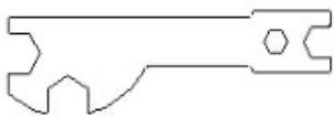
Fig. / Img. / Rys. / Obr. 3
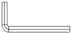
Fig. / Img. / Rys. / Obr. 4

Fig. / Img. / Rys. / Obr. 5

Fig. / Img. / Rys. / Obr. 6

Fig. / Img. / Rys. / Obr. 7
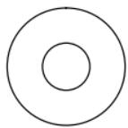
Fig. / Img. / Rys. / Obr. 8

Fig. / Img. / Rys. / Obr. 9

Fig. / Img. / Rys. / Obr. 10

Fig. / Img. / Rys. / Obr. 11

Fig. / Img. / Rys. / Obr. 12

Fig. / Img. / Rys. / Obr. 13
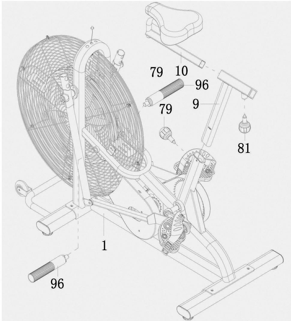
Fig. / Img. / Rys. / Obr. 14
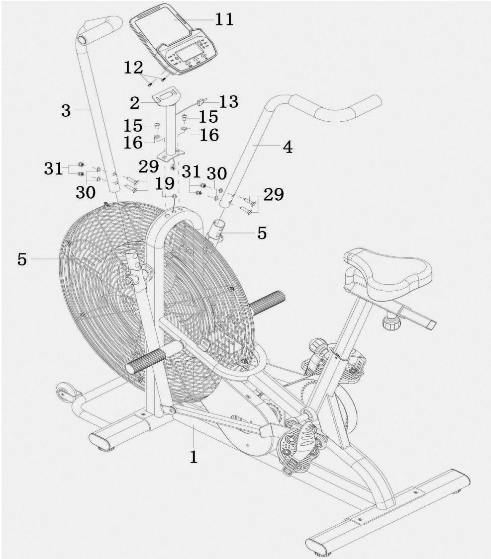
Fig. / Img. / Rys. / Obr. 15
www.cecotec.es


- SOMMAIRE
- INSTRUCTIONS ON BATTERIES
- INSTRUCTIONS DE SÉCURITÉ
- NOTE
- TOOLS AND HARDWARE
- BEFORE USE
- PRODUCT ASSEMBLY
- STEP 1: FRONT AND REAR STABILISERS INSTALLATION
- STEP 2: HANDRAILS, FOOT BARS AND PEDALS INSTALLATION
- STEP 3: SADDLE POST AND FOOTREST INSTALLATION
- ENGLISH
- STEP 4: LEFT AND RIGHT HANDRAIL ARMS AND CONSOLE INSTALLATION
- OPERATION
- KEYS
- MODE
- SET
- RESET
- FUNCTIONS
- INFORMATION ON EXERCISING
- WARM-UP AND COOL-DOWN ROUTINE
- WARM UP
- COOL DOWN
- WARNING
- SHOULDER LIFT
- QUADRICEPS STRETCHING
- TOE TOUCH
- HAMSTRING STRETCHING
- CALF/ACHILLES TENDON STRETCHING
- CLEANING AND MAINTENANCE
- TECHNICAL SPECIFICATIONS
- DISPOSAL OF OLD ELECTRICAL AND ELECTRONIC APPLIANCES
- TECHNICAL SUPPORT AND WARRANTY
- COPYRIGHT
- FRANÇAIS
- PIÈCES ET COMPOSANTS
- IMG. 1
Brand : CECOTEC
Model : Drumfit Wod Rider 3000 Eolo 07230 80
Category : Fitness Equipment