USER MANUAL FWEC2 DAIKIN
INSTALLATION AND OPERATION MANUAL
Advanced electronic controller
Manuale d'installazione e d'uso FWEC2 COMANDO LCD PER TERMINALI
Installation and operation manual FWEC2 LCD CONTROLLER FOR INDOOR UNITS
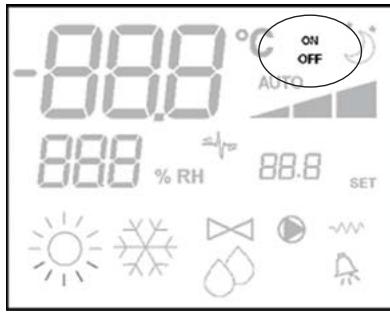
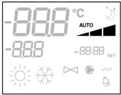
DISPLAY LCD (VEDI FIGURA 2)
| CONFIG. | UNITA' | SCHEMA |
| 01-02-03 | FWL-M-V | FC66002554 (1) |
| FWD | UT66000889 (6) |
| UT66000888 (5) |
| 04-05-06 | FWB | UT66000887 (4) |
| 07-08-09 | FWL-M-V | FC66002555 (2) |
| FWD | UT66000892 (9) |
| UT66000894 (11) |
| UT66000891 (8) |
| UT66000893 (10) |
| 10-11-12 | FWB | UT66000890 (7) |
| 13-14-15 | FWL-M-V | FC66002554 (1) |
| FWD | UT66000889 (6) |
| UT66000888 (5) |
| 16-17-18 | FWB | UT66000887 (4) |
| 19-20-21 | FWL-M-V | FC66002555 (2) |
| FWD | UT66000892 (9) |
| UT66000894 (11) |
| UT66000891 (8) |
| UT66000893 (10) |
| 22-23-24 | FWB | UT66000890 (7) |
| 25-26-27 | FWL-M-V | FC66002554 (1) |
| FWD | UT66000889 (6) |
| UT66000888 (5) |
| 28-29-30 | FWB | UT66000887 (4) |
| 31-32-33 | FWL-M-V | FC66002554 (1) |
| FWD | UT66000889 (6) |
| UT66000888 (5) |
| 34-35-36 | FWB | UT66000887 (4) |
| 37 | FWL-M-V | FC66002555 (2) |
| FWD | UT66000892 (9) |
| UT66000894 (11) |
| UT66000891 (8) |
| UT66000893 (10) |
| 38 | FWB | UT66000890 (7) |
SCHEMI ELETTRICI
LCD controller has been designed to manage the operation of indoor units with single-phase multispeed asynchronous motor. Compared to the standard model it has the added features of advanced humidity control and serial communication.
This controller allows to set (figure 1) up a Master-Slave system (up to 247 slave terminals), in which one of the Microprocessor controllers plays the role of Master and controls all of the other slave elements.
In this case as well the connection is made via an RS485 bus, consisting of a simple shielded 2-conductor cable.
The master (identified by the address 255) sends the following information to the slave controllers:
(1) Operating mode (Cooling or Heating)
(2) Setpoint for room temperature.
The speed selector of each slave controller remains enabled and the room temperature can be adjusted within a range of ± 2^ around the setpoint value transmitted by the master controller.
MAIN FUNCTIONS AND FEATURES:
Air temperature adjustment through automatic variation of fan speed;
Regulation of air temperature via fan on-off control (fan runs at a fixed speed),
Control of On-Off valves for two or four-pipe systems
Control of electrical heater for auxiliary heating.
Cooling/heating switching in the following modes:
Dehumidify Function
Serial Communication
ADDITIONAL FEATURES INCLUDE:
- no-voltage contact for external activation (e.g. window contact, remote ON/OFF, occupancy sensor, etc.) which may enable or disable unit operation (contact logic: see circuit board configuration parameters).
- no-voltage contact for centralised remote Cooling/Heating changeover (contact logic: see circuit board configuration parameters).
no-voltage contact for remote enabling of the economy mode (contact logic: see circuit board configuration parameters).
remote water temperature probe (accessory FWTSKAA)
■ built-in temperature probe
■ built-in humidity probe
remote air temperature probe (accessory FWTSKAA) (this probe, if present, is used in place of the internal one for the measurement of room temperature).
Remote humidity probe (accessory FWHSKAA - to be used in combination with the remote temperature probe)
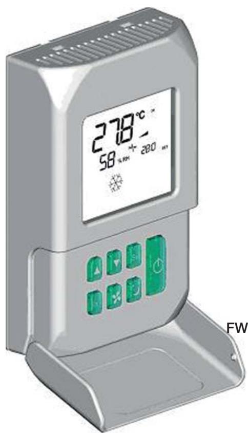
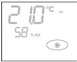
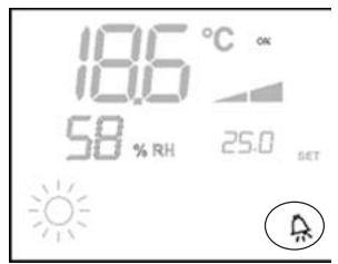
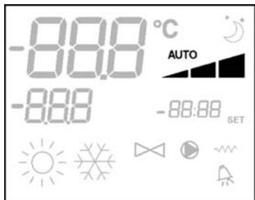
The control panel is composed of:
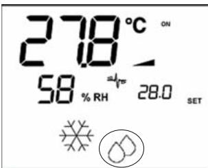
LCD display
keyboard
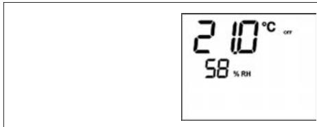
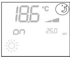
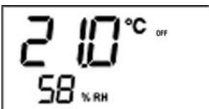
(1) room temperature
(2) room humidity
(3) set temperature
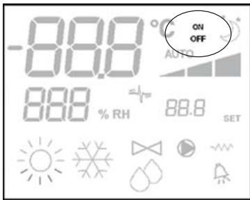
ON fan status. When flashing it indicates that fans are off standing for a call from the thermostat. If the symbol is steadily lit it means that the fans are running
OFF fan status. Fans are off as speed is set to Off or the control is off.
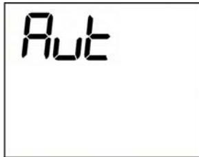
AUTO automatic ventilation logic
fan speed
operation mode: Cooling. When flashing it indicates that water circuit is not enabled to fan ventilation.
operation mode: Heating. When flashing it indicates that water circuit is not enabled to fan ventilation.
Dehumidification. When flashing it indicates that the circuit is not enabled to dehumidification. If the symbol is steadily lit it means that the function is active.
Economy option enabled
Alarm triggered
Minimum Temperature Control
valve open
electrical heater: If the symbol flashes it means that the electrical heater is on; if steadily lit it means only that the electrical heater has been selected
24 serial communication active. The flashing symbol indicates that the controller is the master

On/Off key: Thermostat On/Off. During the procedure of parameter modification, it permits to return to normal operating conditions
Up and Down keys: changing of thermostat setting temperature (Heating:[5.0-30.0°C], Cooling:[10.0-35.0°C]). During the procedure of parameter modification, they are used to select the parameters or to change their value

SEL key: in the heating mode, the electrical heater element can be selected as auxiliary function

Mode key: selection of Heating/Cooling operating mode

Fan key: selection of operating speed

EC key: selection of Economy mode
ACTIVE KEY COMBINATIONS

With OFF thermostat: access to the parameter configuration procedure
With ON thermostat: display of current water temperature

Selection of Minimum air temperature function

Selection of dehumidify option
BOARD CONFIGURATION
The board can be configured according to the type of unit/ system to be governed by changing some parameters.
PARAMETER LIST
- P00 = controller configuration (see "Available configurations") to select the type of unit to be managed.
- P01 = type of controller installation
- 000: on the unit
- 001: wall mounted
- P02 = Modbus address (in order for the change in this parameter to become active (excepting in the case of internal transfer between values, it is necessary to switch the power off and back on again at the end of programming) -0: serial communication disabled
-1-247: slave
-255: master
- P03 = neutral zone [20 - 50^ / 10] ; parameter used in case of configurations with automatic cooling/heating changeover according to air temperature.
P04 = water sensor
-0: not available
-1: available
Based on the set value, the sensor alarm and the electrical heater functions will be controlled
P06 = logic for use of digital input 1:
- : [open/closed] = [Cooling/Heating] = [-/ECO]
- [open/closed] = [Heating/Cooling] = [ECO/-]
P07 = logic for use of digital input 2:
- : [open/closed] = [OFF/ON] = [-/ECO]
1: [open/closed] = [On/Off] = [ECO/-]
P08 = Remote humidity sensor
- : not available
- 1:available
Based on the set value, the associated probe alarm will be triggered accordingly.
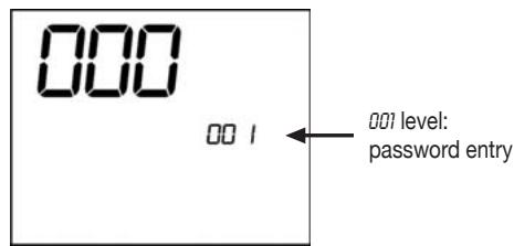
PARAMETER CONFIGURATION PROCEDURE
Switch the thermostat OFF

Push the MODE keys at the same time
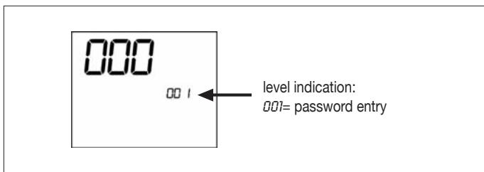
Use keys to modify the display value up to the password value "10", and press SEL. If it is correct, you will have access to the parameters
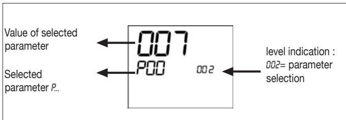
Use keys to scroll the various parameters (see "Parameter list" described above)
Press to confirm the parameter change (the value will start flashing)
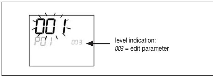
use keys to change the value
Press to save the new value setting or to cancel the modification
After completing the modification of the parameters concerned press key to exit the procedure
N.B.: the parameter configuration phase is of limited duration. Once a certain time has elapsed (around 2 minutes) the thermostat will switch back into the Off status and only the saved changes will be retained.
AVAILABLE CONFIGURATIONS (PARAMETER P00)
The LCD controller can be configured in various ways according to the type of system. Various configurations can be obtained through the P0D parameter (see configuration procedure of controller parameters).
001
System pipes: 2
Valve: NO
Electrical heater: NO
Fan speed: 3
Summer/winter switching logic: LOCAL MANUAL
002
System pipes: 2
Valve: NO
Electrical heater: NO
Fan speed: 3
Summer/winter switching logic: REMOTE MANUAL
003
System pipes: 2
Valve: NO
Electrical heater: NO
Fan speed: 3
Summer/winter switching logic: AUTOMATIC WATER SIDE
004
System pipes: 2
Valve: NO
Electrical heater: NO
Fan speed: 4
Summer/winter switching logic: LOCAL MANUAL
005
System pipes: 2
Valve: NO
Electrical heater: NO
Fan speed: 4
Summer/winter switching logic: REMOTE MANUAL
008
System pipes: 2
Valve: NO
Electrical heater: NO
Fan speed: 4
Summer/winter switching logic: AUTOMATIC WATER SIDE
007
System pipes: 2
Valve: NO
Electrical heater: YES
Fan speed: 3
Summer/winter switching logic: LOCAL MANUAL
008
System pipes: 2
Valve: NO
Electrical heater: YES
Fan speed: 3
Summer/winter switching logic: REMOTE MANUAL
009
System pipes: 2
Valve: NO
Electrical heater: YES
Fan speed: 3
Summer/winter switching logic: AUTOMATIC AIR SIDE
010
System pipes: 2
Valve: NO
Electrical heater: YES
Fan speed: 4
Summer/winter switching logic: LOCAL MANUAL
011
System pipes: 2
Valve: NO
Electrical heater: YES
Fan speed: 4
Summer/winter switching logic: REMOTE MANUAL
012
System pipes: 2
Valve: NO
Electrical heater: YES
Fan speed: 4
Summer/winter switching logic: AUTOMATIC AIR SIDE
013
System pipes: 2
Valve: 2-3 WAYS
Electrical heater: NO
Fan speed: 3
Summer/winter switching logic: LOCAL MANUAL
014
System pipes: 2
Valve: 2-3 WAYS
Electrical heater: NO
Fan speed: 3
Summer/winter switching logic: REMOTE MANUAL
015
System pipes: 2
Valve: 2-3 WAYS
Electrical heater: NO
Fan speed: 3
Summer/winter switching logic: AUTOMATIC WATER SIDE
016
System pipes: 2
Valve: 2-3 WAYS
Electrical heater: NO
Fan speed: 4
Summer/winter switching logic: LOCAL MANUAL
017
System pipes: 2
Valve: 2-3 WAYS
Electrical heater: NO
Fan speed: 4
Summer/winter switching logic: REMOTE MANUAL
AVAILABLE CONFIGURATIONS (PARAMETER P00)
018
System pipes: 2
Valve: 2-3 WAYS
Electrical heater: NO
Fan speed: 4
Summer/winter switching logic: AUTOMATIC WATER SIDE
019
System pipes: 2
Valve: 3 WAYS
Electrical heater: YES
Fan speed: 3
Summer/winter switching logic: LOCAL MANUAL
020
System pipes: 2
Valve:3WAYS
Electrical heater: YES
Fan speed: 3
Summer/winter switching logic: REMOTE MANUAL
021
System pipes: 2
Valve:3WAYS
Electrical heater: YES
Fan speed: 3
Summer/winter switching logic: AUTOMATIC AIR SIDE
022
System pipes: 2
Valve: 3 ways
Electrical heater: YES
Fan speed: 4
Summer/winter switching logic: LOCAL MANUAL
023
System pipes: 2
Valve:3WAYS
Electrical heater: YES
Fan speed: 4
Summer/winter switching logic: REMOTE MANUAL
024
System pipes: 2
Valve:3WAYS
Electrical heater: YES
Fan speed: 4
Summer/winter switching logic: AUTOMATIC AIR SIDE
025
System pipes: 4
Valve: NO
Electrical heater: NO
Fan speed: 3
Summer/winter switching logic: LOCAL MANUAL
026
System pipes: 4
Valve: NO
Electrical heater: NO
Fan speed: 3
Summer/winter switching logic: REMOTE MANUAL
027
System pipes: 4
Valve: NO
Electrical heater: NO
Fan speed: 3
Summer/winter switching logic: AUTOMATIC AIR SIDE
028
System pipes: 4
Valve: NO
Electrical heater: NO
Fan speed: 4
Summer/winter switching logic: LOCAL MANUAL
029
System pipes: 4
Valve: NO
Electrical heater: NO
Fan speed: 4
Summer/winter switching logic: REMOTE MANUAL
030
System pipes: 4
Valve: NO
Electrical heater: NO
Fan speed: 4
Summer/winter switching logic: AUTOMATIC AIR SIDE
031
System pipes: 4
Valve: 2-3 WAYS
Electrical heater: NO
Fan speed: 3
Summer/winter switching logic: LOCAL MANUAL
032
System pipes: 4
Valve: 2-3 WAYS
Electrical heater: NO
Fan speed: 3
Summer/winter switching logic: REMOTE MANUAL
033
System pipes: 4
Valve: 2-3 WAYS
Electrical heater: NO
Fan speed: 3
Summer/winter switching logic: AUTOMATIC AIR SIDE
034
System pipes: 4
Valve: 2-3 WAYS
Electrical heater: NO
Fan speed: 4
Summer/winter switching logic: LOCAL MANUAL
035
System pipes: 4
Valve: 2-3 WAYS
Electrical heater: NO
Fan speed: 4
Summer/winter switching logic: REMOTE MANUAL
AVAILABLE CONFIGURATIONS (PARAMETER P00)
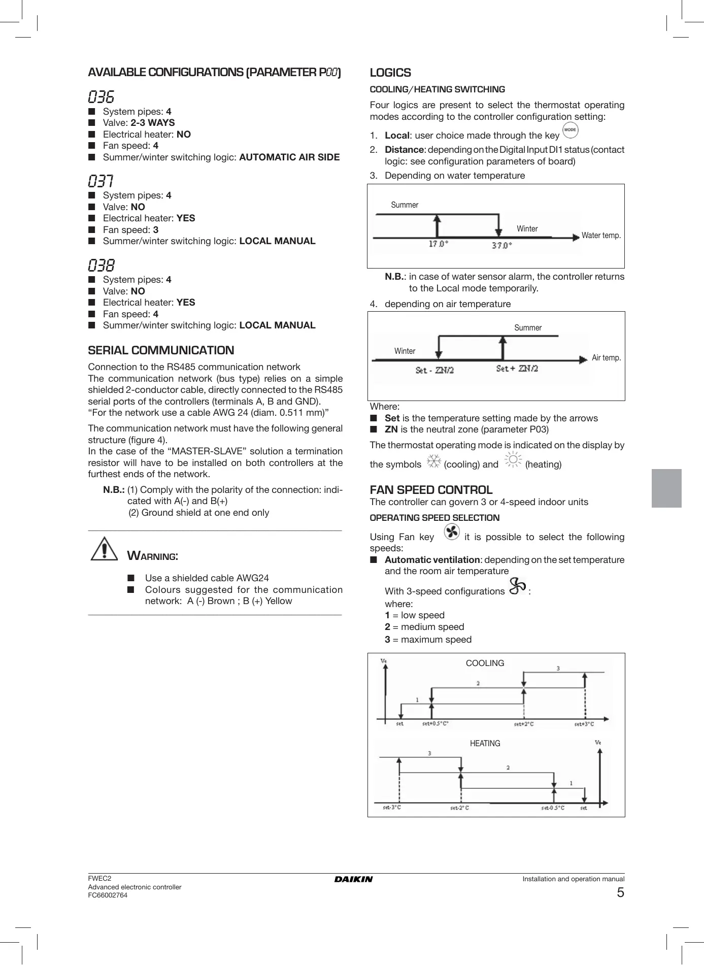
036
System pipes: 4
Valve: 2-3 WAYS
Electrical heater: NO
Fan speed: 4
Summer/winter switching logic: AUTOMATIC AIR SIDE
037
System pipes: 4
Valve: NO
Electrical heater: YES
Fan speed: 3
Summer/winter switching logic: LOCAL MANUAL
038
System pipes: 4
Valve: NO
Electrical heater: YES
Fan speed: 4
Summer/winter switching logic: LOCAL MANUAL
SERIAL COMMUNICATION
Connection to the RS485 communication network
The communication network (bus type) relies on a simple shielded 2-conductor cable, directly connected to the RS485 serial ports of the controllers (terminals A, B and GND).
"For the network use a cable AWG 24 (diam. 0.511 mm)"
The communication network must have the following general structure (figure 4).
In the case of the "MASTER-SLAVE" solution a termination resistor will have to be installed on both controllers at the furthest ends of the network.
N.B.: (1) Comply with the polarity of the connection: indicated with A(-) and B(+)
(2) Ground shield at one end only

WARNING:
Use a shielded cable AWG24
Colours suggested for the communication network: A (-) Brown; B (+) Yellow
LOGICS
COOLING/HEATING SWITCHING
Four logics are present to select the thermostat operating modes according to the controller configuration setting:
- Local: user choice made through the key
- Distance: depending on the Digital Input DI1 status (contact logic: see configuration parameters of board)
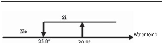
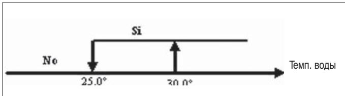
- Depending on water temperature
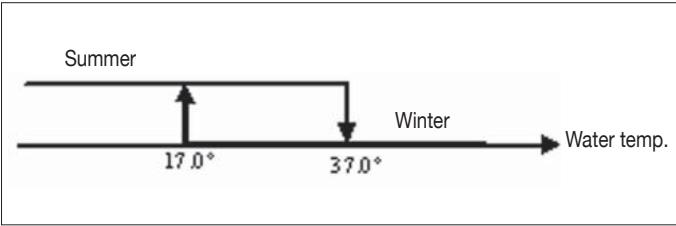
N.B.: in case of water sensor alarm, the controller returns to the Local mode temporarily.
- depending on air temperature
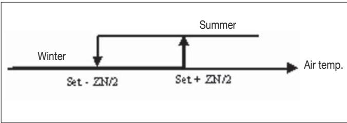
Where:
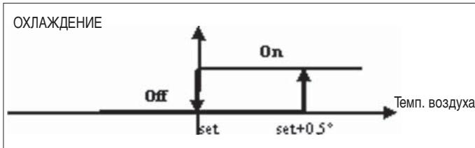
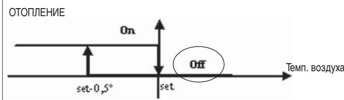
Set is the temperature setting made by the arrows
ZN is the neutral zone (parameter P03)
The thermostat operating mode is indicated on the display by the symbols (cooling) and (heating)
FAN SPEED CONTROL
The controller can govern 3 or 4-speed indoor units
Using Fan key it is possible to select the following speeds:
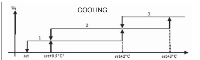
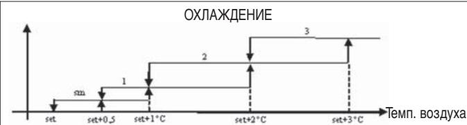
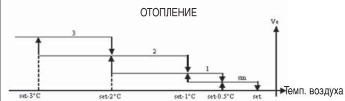
Automatic ventilation: depending on the set temperature and the room air temperature
With 3-speed configurations :
where:
1 = low speed
2 = medium speed
3 = maximum speed
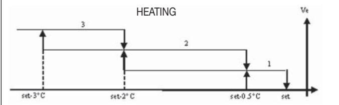
With 4-speed configurations

where:
sm = extra-low speed
1 = low speed
2 = medium speed
3 = maximum speed
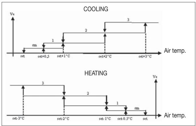
N.B.: in case of 4-speed configuration and valve, ventilation in heating mode is shifted by 0.5^ C to permit a natural convection phase
Speed disabled: Can be selected only in heating mode and with 4-speed configuration only. The indoor unit operates by natural convection only.

Extra low speed: can be selected only with 4-speed configuration. It works at extra low speed only.

Low speed

Medium speed

High speed
N.B.: In the case of fixed speed, the fan on/off logic will be equivalent to the automatic logic.
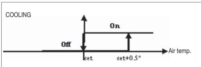
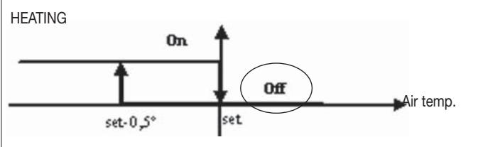
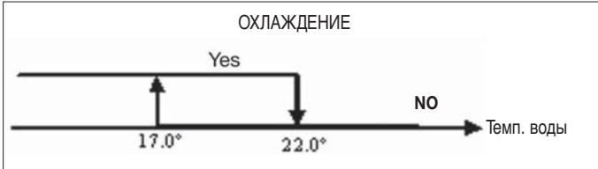
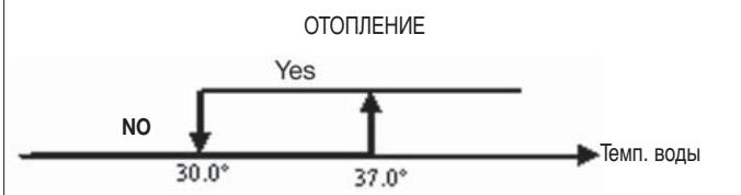
WATER CONTROL
The ventilation operation depends on the system water temperature control. Based on the operation mode, different heating or cooling thresholds will be enabled.
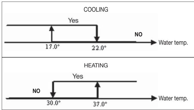
Upon a call of the thermostat, the absence of the enabling signal will be indicated on the display by the flashing of the
symbol representing the active mode (or
The enabling signal is ignored:
if the water sensor is not included (P04 = 0) or in alarm status because disconnected
in the cooling mode with 4-pipe configurations
LOGICS
FORCED OVERRIDES
The normal fan operating logic will be ignored in particular override situations that may be necessary to ensure correct control of the temperature or the unit's operation. This may occur:
in the cooling mode:
on-board controller (P01 = 0) and configurations with valve: the minimum speed available will be maintained even once the temperature has been reached.
on-board controller and valveless configurations: every 10 minutes in which the fan remains idle a 2 minute fan rotation is carried out at medium speed to enable the air sensor to read the room temperature more accurately.
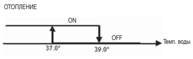
In the heating mode
■ while the electrical heater is on: the fan is forced to run at medium speed
■ once the electrical heater has gone off: a 2 minute postventilation cycle will be run at medium speed. (N.B.: this cycle will be completed even if the thermostat is switched off or in the event of a changeover to the cooling mode)
DISPLAY
The display shows the fan status
On flashing: fan in standby mode
On steadily lit: fan on
OFF: fan disabled to operate by natural convection only
and fan speed (with indication of "automatic" logic if proper) enabled or selected (in case of stand-by fan)

Extra low speed
Low speed
Medium speed
High speed
N.B.: if the active speed is different from the one selected by the user (in the case of a forced override), pressing the
button Fan the selected speed will be displayed; pressing again will change this setting.
VALVE
The controller can manage 2 or 3-way On/OFF type valves, with 230V voltage.
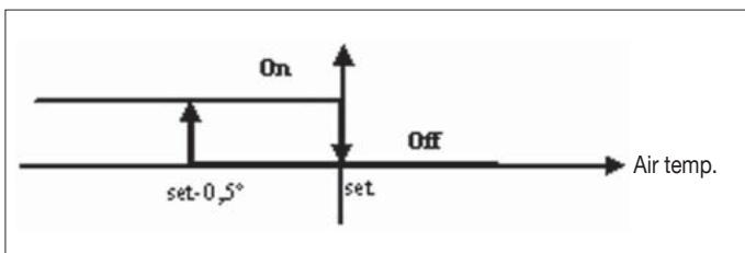
OPENING
The valve opening is controlled according to the operating setpoint and air temperature setpoint
WATER CONTROL
The checking of water temperature to enable valve opening is a function that concerns only configurations with 3-way valves and electrical heater.
In such configurations the water temperature will be checked in the following cases:
Heating with electrical heater: operation of the electrical heater will force the fan to switch on; it is therefore necessary to prevent excessively cold water from passing through the unit.
- Post-ventilation due to switching off of the electrical heater: this function will be maintained until the set time has elapsed, even if the operating mode is changed. During post-ventilation the water temperature enabling signal will coincide with the one seen for fan operation.
DISPLAY
The active valve indication on the display will be shown by the symbol 品
ELECTRICAL HEATER
The electrical heater is a device used where necessary in the heating mode.
SELECTION
If provided for in the configuration, the electrical heater can be selected in the heating mode by pressing the Sel key
ACTIVATION
If the electrical heater is selected by the user, it will be activated on a call from the thermostat based on the room temperature
N.B.: switching it on will force the fan on as well
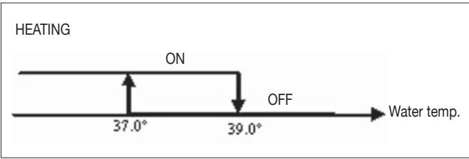
WATER CONTROL
Enabling of the electrical heater is tied to the water temperature. The related enabling logic is described below The enabling signal will not be given if the water sensor is either not present or disconnected
DISPLAY
The display will show the following information
■ electrical heater selected by the user: steadily symbol
active electrical heater: flashing symbol
ECONOMY
The Economy function corrects the setpoint by 2.5^ and forces the fan to run at the minimum available speed to reduce unit operation.
Cooling: setpoint + 2.5°C
Heating: setpoint -2.5°C
ACTIVATION
This function can be activated by pressing the key

DISPLAY
The Economy function is shown on the display by the symbol
MINIMUM TEMPERATURE CONTROL
This logic makes it possible to keep the room temperature from falling too far when the thermostat is off by forcing the unit into the heating mode if necessary and for the time required. If the electrical heater is present, it will be used only if it was previously selected as a resource in the heating mode.
SELECTION
When the thermostat is off, you can select the minimum temperature control by pressing at the same time the keys

The same key combination disables this function.
ACTIVATION
If this control is selected, the unit will switch on when the room temperature falls below 9^ .
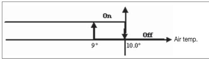
When temperature exceeds 10^ the thermostat will resume the Off status.
N.B.: Any Off command from digital input will disable this logic
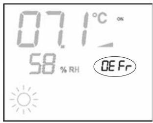
DISPLAY
The display shows the following information
Minimum temperature control selected: symbol
Minimum temperature control enabled: DEFR
DEHUMIDIFICATION
The dehumidification function, enabled only in the cooling mode, activates operation of the indoor unit in order to achieve a 10% reduction in the level of humidity present in the room at the time the function itself was selected.
SELECTION
Dehumidification can be selected/unselected in the Cooling
mode by simultaneously pressing the buttons. If the water probe (P04 = 0) or the remote humidity probe is not available, in cases where the controller is installed directly on the unit (P08 = 0) , selection will not be enabled. If selected, the dead band for automatic switching on the air side will be brought to 5^
LOGIC
Once selected, the dehumidification logic sets the target humidity level as the humidity present at the time the function was selected minus 10% . Where the room humidity is less than 40% the target level will be set at 30% .
The fan will be forced to run at low speed or, if the temperature is much higher than the setpoint, at medium speed.
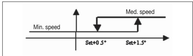
In order to bring the humidity to the set value, the fan (and valve, if present) will be activated even if the room temperature has already reached the programmed setpoint (indicated on the display by the symbol 3). Should the room temperature fall too far below this threshold, the logic will be temporarily inhibited.
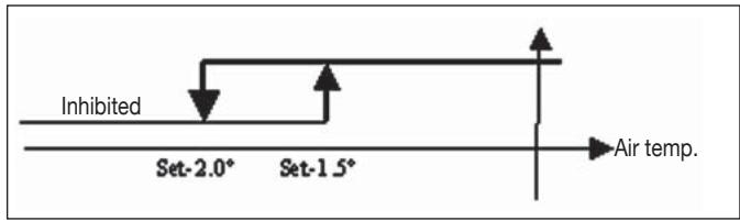
WATER CONTROL
Enabling of the dehumidification function is tied to the water temperature. The related enabling logic is described below
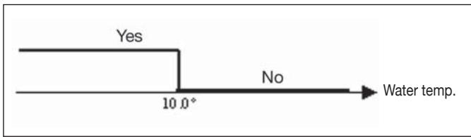
If enabling conditions do not exist, the dehumidification function will be temporarily inhibited.
The same will occur in the event that the probe is disconnected.
N.B.: once the target level of humidity is reached or the controller is switched off, the dehumidify option will be unselected
DISPLAY
The display shows the following information:
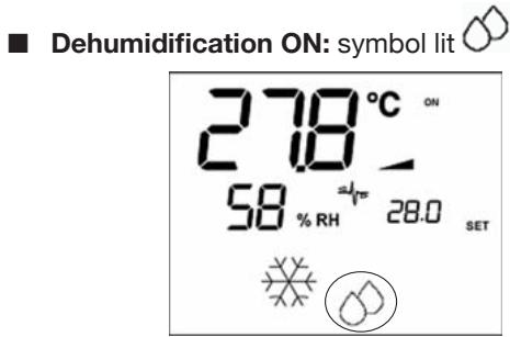
Dehumidification temporarily inhibited: flashing symbol
ALARMS
This control manages two types of alarms:
■ Serious Alarms: cause the forced switching off of the thermostat
Non-serious Alarms: do not cause the forced switching off of the thermostat, but disable possible critical functions
SERIOUS ALARMS
Code R01 = error of external air temperature sensor (in case of on-board thermostat)
Code R02 = error of internal air temperature sensor (in case of wall mounted thermostat and disconnected external air temperature sensor)

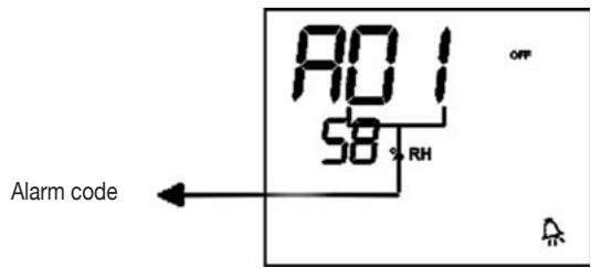
NON-SERIOUS ALARMS
Thermostat OFF
Thermostat ON
Code R03 = water sensor error
Code R04 = remote humidity probe error (only if a remote temperature probe is installed)
Code R05 = internal humidity probe error
N.B.: the alarm code is displayed only when the thermostat is switched off
MODBUS
The protocol implemented in the controller is Modbus RTU (9600, N, 8, 2) on RS485
FUNCTIONS IMPLEMENTED
0x03 : Read Holding Registers
0x04:Read Input Registers
0x10 : Write Multiple registers
EXCEPTIONS IMPLEMENTED
Exception Code 02: Invalidate data address
LIST OF SUPERVISION PARAMETERS
| ADDRESS | REGISTER | TYPE | U.M. |
| 0 | Status | R | - |
| 1 | Speeds | R | - |
| 2 | Air temperature | R | [°C/10] |
| 3 | Humidity | R | % |
| 4 | Water temperature | R | [°C/10] |
| 5 | P00:Configuration | R | - |
| 6 | P05:Config. DIN | R | - |
| 7 | T. Active setpoint | R | [°C/10] |
| 8 | T. User setpoint | R | [°C/10] |
| 9 | LCD version | R | - |
| | | |
| 50 | Digital 1 | R/W | - |
| 51 | - | R/W | - |
| 52 | Setpoint - Cooling | R/W | [°C/10] |
| 53 | Setpoint - Heating | R/W | [°C/10] |
| 54 | Minimum Setpoint - Cool. | R/W | [°C/10] |
| 55 | Maximum Setpoint - Cool. | R/W | [°C/10] |
| 56 | Minimum Setpoint - Heat. | R/W | [°C/10] |
| 57 | Maximum Setpoint - Heat. | R/W | [°C/10] |
| 58 | Speeds | R/W | - |
| 59 | Economy Correction | R/W | [°C/10] |
DESCRIPTION OF READ-ONLY REGISTERS [R]
Staus"REGISTER
| H |
| Bit 15 | Bit 14 | Bit 13 | Bit 12 | Bit 11 | Bit 10 | Bit 9 | Bit 8 |
| - | - | P04 | Deum | P06 | P07 | DI2 | DI1 |
| L |
| Bit 7 | Bit 6 | Bit 5 | Bit 4 | Bit 3 | Bit 2 | Bit 1 | Bit 0 |
| Vh | Vc | Alarm | MinT | Eco | P01 | S/W | On/Off |
- On/Off: unit status (0: Off, 1=On)
- S/W: operation mode (0: S=cooling,1:W=heating)
- P01: "on unit/wall-mounted" parameter
- Eco: Economy logic active
Min.T: Minimum Temperature logic selected
- Alarm: general alarm indication (activated when any of the managed alarms is triggered)
- Vc: status of digital output Vc
- Vh: status of digital output Vh
- DI1: logical value of dig. input 1 (the physical status of the input depends on the associated logic)
- DI2: logical value of dig. input 2 (the physical status of the input depends on the associated logic)
- P07: "DIN 2 Logic" parameter
- P06: "DIN 1 Logic" parameter
- Dehum: dehumidification ON (0:no, 1=yes)
- P04: "water probe present" parameter
■ "SPEED" REGISTER: current operating speed of the indoor unit
- 0: fan OFF
- 1: extra-low speed
- 2: low speed
- 3: medium speed
- 4: high speed
■ "AIR TEMPERATURE" REGISTER: room temperature read by the controller and shown on the display (N.B.: this temperature corresponds to the reading of the remote probe if the controller is located on the unit, or the reading of the internal probe in the case of a wall-mounted controller and remote probe disconnected)
■ “HUMIDITY” REGISTER: room humidity read by the controller via the probe associated with the temperature probe used
■ "WATER TEMPERATURE" REGISTER: value read by the water probe (SW)
“P00” Register: “Controller configuration” parameter
“T. ACTIVE SETPOINT” Register: setpoint used for temperature control
“T. USER SETPOINT” Register: setpoint programmed by the user (it may differ from the active setpoint due to corrections based on economy logics,...or use of the setpoint imposed by the supervision software)
"LCD VERSION" Register : defines the controller type and software version installed (0xHHSS: HH: ASCII character, SS:sw version)
DESCRIPTION OF READ/WRITE REGISTERS [R/W]
"Digital 1" REGISTER:
| H |
| Bit 15 | Bit 14 | Bit 13 | Bit 12 | Bit 11 | Bit 10 | Bit 9 | Bit 8 |
| En.Vel | En.Min/Max | En.Set | En.MinT | En.ECO | En.RE | En.S/W | En.On/Off |
| L |
| Bit 7 | Bit 6 | Bit 5 | Bit 4 | Bit 3 | Bit 2 | Bit 1 | Bit 0 |
| - | - | Lock | MinT | Eco | RE | S/W | On/Off |
- On/Off: On/Off via supervision system
- S/W: Mode set via supervision system (0: Cooling, 1: Heating)
- RE: selection of electrical heater via supervision system
- Eco: Economy mode ON via supervision system
- MinT.: Minimum Temperature control ON via supervision system
- Lock: keypad lock (0: unlocked, 1: locked)
- En.On/Off :enabling of On/Off control via supervision system
- En.S/W: enabling of mode control via supervision system
- En.RE: enabling of selection of electrical heater function via supervision system
- En.ECO: enabling of economy mode activation via supervision system
- En.MinT: enabling of selection of Minimum Temperature logic via supervision system
- En.Set: enabling of forced override of setpoint via supervi-sion system
- En.Min/Max: enabling of setpoint thresholds via supervi-sion system
- En.Vel: enabling of selection of fan speed via supervision system
“SETPOINT - COOLING” Register: setpoint imposed by supervision system for the Cooling mode
■ “SETPOINT - HEATING” Register: setpoint imposed by supervision system for the Heating mode
"MINIMUM SETPOINT - COOL." Register : lower limit for setpoint in cooling mode
MAXIMUM SETPOINT - COOL." Register ": upper limit for setpoint in cooling mode
■ “MINIMUM SETPOINT - HEAT.” Register “: lower limit for setpoint in heating mode
■ “MAXIMUM SETPOINT - HEAT.” Register “: upper limit for setpoint in heating mode
■ "SPEED" Register: selection of fan speed via supervision system
ECONOMY CORRECTION" Register: correction of setpoint in the case of economy mode imposed by supervisor (this correction is an amount subtracted from or added to the setpoint, based on the operating mode)
SELF-DIAGNOSIS PROCEDURE
This procedure allows you to check whether the individual outputs of the controller function correctly.
To run the procedure, follow the directions below:
Switch the thermostat off
Push the keys at the same time SEL MODE
Use the keys to change the value on the display until arriving at the password for self-diagnosis (030) and press SEL.
The following screen will be displayed:
Press the button to switch on the various thermostat outputs in sequence.
| Symbol | Actuation | Terminals |
| × | Extra low speed | N-V0 |
| - | Min. speed | N-V1 |
| - | Med. speed | N-V2 |
| - | Max. speed | N-V3 |
| × | Valve | N-Vc |
| ×× | Electrical heater
Second valve | N-Vh |
| no symbol | no active outlet | |
The electronic controller outputs can be checked one by one either by observing the respective component (valve, fan.) or verifying whether a voltage of 230V is present at the corresponding terminals.
To exit the self-diagnosis procedure press (after a few minutes the thermostat will automatically exit in any case).
Where
| Vc | Valve |
| Vh | Heat valve/heater |
| V0 | Extra low speed |
| V1 | Low speed. |
| V2 | Medium speed |
| V3 | High speed |
| N | Neutral |
| L | Phase |
| PE | Ground |
| A-B-GND | RS 485 |
| SU | Remote humidity sensor |
| SW | Water sensor |
| SA | Remote air probe |
| DI1 | Dig.1 input |
| CI12 | DI1-2 Common |
| DI2 | Dig. 2 input |
N.B.:
For power connections use cable w/ cross section size of 2mm^2
For digital inputs used AWG 24 cable
For sensor extensions and RS485 use AWG 24 shielded cable
WIRING DIAGRAMS
(See Wiring Diagrams enclosed)
UNIT TABLE/DIagrams
| UNIT | TYPE | CONFIGURATION | DIAGRAM |
| FWL-M-V | - | 1-2-3-13-14-15-25-26-27-31-32-33 | FC66002554 |
| 7-8-9-19-20-21-37 | FC66002555 |
| FWB | - | 4-5-6-16-17-18-28-29-30-34-35-36 | UT66000887 |
| 10-11-12-22-23-24-38 | UT66000890 |
| FWD | 04/12 | 1-2-3-13-14-15-25-26-27-31-32-33 | UT66000889 |
| 7-8-9-19-20-21-37 | UT66000892 |
| 06/12 3PH | 7-8-9-19-20-21-37 | UT66000894 |
| 16/18 | 1-2-3-13-14-15-25-26-27-31-32-33 | UT66000888 |
| 7-8-9-19-20-21-37 | UT66000891 |
| 16/18 3PH | 7-8-9-19-20-21-37 | UT66000893 |
| EPIMSB6 | FWL-M-V | - | FC66002557 |
| FWB | - |
| FWD | - |
WIRING DIAGRAMS
(See Wiring Diagrams enclosed)
CONFIGURATION TABLE/DIagrams
| CONFIG. | UNIT | DIAGRAM |
| 01-02-03 | FWL-M-V | FC66002554 (1) |
| FWD | UT66000889 (6) |
| UT66000888 (5) |
| 04-05-06 | FWB | UT66000887 (4) |
| 07-08-09 | FWL-M-V | FC66002555 (2) |
| FWD | UT66000892 (9) |
| UT66000894 (11) |
| UT66000891 (8) |
| UT66000893 (10) |
| 10-11-12 | FWB | UT66000890 (7) |
| 13-14-15 | FWL-M-V | FC66002554 (1) |
| FWD | UT66000889 (6) |
| UT66000888 (5) |
| 16-17-18 | FWB | UT66000887 (4) |
| 19-20-21 | FWL-M-V | FC66002555 (2) |
| FWD | UT66000892 (9) |
| UT66000894 (11) |
| UT66000891 (8) |
| UT66000893 (10) |
| 22-23-24 | FWB | UT66000890 (7) |
| 25-26-27 | FWL-M-V | FC66002554 (1) |
| FWD | UT66000889 (6) |
| UT66000888 (5) |
| 28-29-30 | FWB | UT66000887 (4) |
| 31-32-33 | FWL-M-V | FC66002554 (1) |
| FWD | UT66000889 (6) |
| UT66000888 (5) |
| 34-35-36 | FWB | UT66000887 (4) |
| 37 | FWL-M-V | FC66002555 (2) |
| FWD | UT66000892 (9) |
| UT66000894 (11) |
| UT66000891 (8) |
| UT66000893 (10) |
| 38 | FWB | UT66000890 (7) |
WIRING DIAGRAMS
Key to symbols used in wiring diagrams:
| Vo | Extra low speed |
| V1 | Min. speed |
| V2 | Med. speed |
| V3 | Max. speed |
| L | Phase |
| PE | Ground |
| N | Neutral |
| RE | Electrical heater |
| SW | Water sensor |
| SA | Air sensor |
| SU | Humidity sensor |
| BK | Black (Max. speed) |
| BU | Blue (Med. speed) |
| RD | Red (Extra low speed) |
| WH | White (common) |
| GY | Grey |
| BN | Brown (Min. speed) |
| GN | Green |
| YE | Yellow |
| MS | Flap microswitch |
| DI1 | Digital 1 input |
| DI2 | Digital 2 input |
| CI2 | Digital input common |
| A/B/GND | RS 485 |
| F | Fuse (not supplied) |
| IL | Circuit breaker (not supplied) |
| CN | Terminal board |
| RHC | Heating/Cooling remote selecting switch |
| EXT | Remote ON/OFF contact |
| EPIMB6 | Circuit board to control 4 indoor units |
| EPIB6 | Circuit board for FWD units |
| M | Fan motor |
| VHC | Solenoid valve -Cool/Heat. |
| VC | Solenoid valve - Cooling |
| VH | Solenoid valve - Heating |
| TSA | Automatic safety thermostat |
| TSM | Safety fuse |
| SC | Wiring box |
| ...... | Electrical connections to be made by installer |
| ECONOMY | COMFORT / ECONOMY remote selecting switch |
INSTALLATION OF WALL-MOUNTED CONTROLLER
NB: for wall mounting of the controller it is advisable to use an electric box behind the controller to accommodate the cables.
NB: Prior to installation, carefully remove the protective film from the display; removal of the film may cause some dark streaks to appear on the display but these will disappear after a few seconds and are not signs of a controller defect.
INSTRUCTIONS FOR WALL MOUNTING
- Remove the fastening screw of the controller (FIGURE 8).
- If a 503 electrical enclosure is used, pass the cables through the slot at the bottom of the controller and use the holes provided for fastening.
- Otherwise, in the wall where you wish to mount the controller, drill holes to match up with the fastening slots (5x8mm) on the base of the controller; pass the cables through the slot on the base and screw it to the wall (previously drilled) (FIGURE 9).
- Make the electrical connections to the indoor unit terminal block as per the wiring diagram.
- Close the controller box and fix with the screw removed as described at point 1.
TECHNICAL DATA
| Power supply | 90-250Vac 50/60Hz |
| Electrical input 8W |
| Protection fuse 500mA delayed |
| Operating temp. | Range 0-50°C |
| Storage temp. | Range -10-60°C |
| Relay | NO 5A @ 240V (Resistive) |
| insulation: coil-contact distance 8 mm |
| 4000V coil-relay dielectric |
| Max ambient temperature 105°C |
| Connectors | 250V 10A |
| Digital inputs | Clean contact |
| Closing current 2mA |
| Max. closing resistance 50 Ohm |
| Analog inputs | Temperature and relative humidity probes |
| Power outputs | Relay (see above) |
| Temperature sensors | NTC sensors 10K Ohm @25°C |
| Range -25-100°C |
| Humidity probe | Resistive-type probe |
| Range 20-90%RH |
CHARACTERISTIQUES GENÉRALES
Tuyaux installation: 4
EXCEPTIONS APLIQUÉES
Exception Code 02: Invalidate data address
LISTE PARAMÉTRES DE SUPERVISION
| ADRESSE | REGISTRE | TYPE | U.M. |
| 0 | États | R | - |
| 1 | Vitesse | R | - |
| 2 | Température air: | R | [°C/10] |
| 3 | Humidité | R | % |
| 4 | Température eau: | R | [°C/10] |
| 5 | P00: Configuration | R | - |
| 6 | P05: Config. DIN | R | - |
| 7 | T. Setpoint actif | R | [°C/10] |
| 8 | T. Setpoint utiliser | R | [°C/10] |
| 9 | Version LCD | R | - |
| | | |
| 50 | Numériques 1 | R/W | - |
| 51 | - | R/W | - |
| 52 | Setpoint - Rafraîchissement | R/W | [°C/10] |
| 53 | Setpoint - Chauffage | R/W | [°C/10] |
| 54 | Setpoint min. - rafraîch. | R/W | [°C/10] |
| 55 | Setpoint max. - rafraîch. | R/W | [°C/10] |
| 56 | Setpoint min. - chauff. | R/W | [°C/10] |
| 57 | Setpoint max. - chauff. | R/W | [°C/10] |
| 58 | Vitesse | R/W | - |
| 59 | Correction Economy | R/W | [°C/10] |
DESCRIPTION REGISTRES DE LECTURE SEULEMENT [R]
■ Registre "ÉTATS"
| H |
| Bit 15 | Bit 14 | Bit 13 | Bit 12 | Bit 11 | Bit 10 | Bit 9 | Bit 8 |
| - | - | P04 | Déshum | P06 | P07 | DI2 | DI1 |
| L |
| Bit 7 | Bit 6 | Bit 5 | Bit 4 | Bit 3 | Bit 2 | Bit 1 | Bit 0 |
| Vh | Vc | Alarme | MinT | Eco | P01 | S/W | ON/OFF |
| CONFIG. | UNITÉ | SCHEME |
| 01-02-03 | FWL-M-V | FC66002554 (1) |
| FWD | UT66000889 (6) |
| UT66000888 (5) |
| 04-05-06 | FWB | UT66000887 (4) |
| 07-08-09 | FWL-M-V | FC66002555 (2) |
| FWD | UT66000892 (9) |
| UT66000894 (11) |
| UT66000891 (8) |
| UT66000893 (10) |
| 10-11-12 | FWB | UT66000890 (7) |
| 13-14-15 | FWL-M-V | FC66002554 (1) |
| FWD | UT66000889 (6) |
| UT66000888 (5) |
| 16-17-18 | FWB | UT66000887 (4) |
| 19-20-21 | FWL-M-V | FC66002555 (2) |
| FWD | UT66000892 (9) |
| UT66000894 (11) |
| UT66000891 (8) |
| UT66000893 (10) |
| 22-23-24 | FWB | UT66000890 (7) |
| 25-26-27 | FWL-M-V | FC66002554 (1) |
| FWD | UT66000889 (6) |
| UT66000888 (5) |
| 28-29-30 | FWB | UT66000887 (4) |
| 31-32-33 | FWL-M-V | FC66002554 (1) |
| FWD | UT66000889 (6) |
| UT66000888 (5) |
| 34-35-36 | FWB | UT66000887 (4) |
| 37 | FWL-M-V | FC66002555 (2) |
| FWD | UT66000892 (9) |
| UT66000894 (11) |
| UT66000891 (8) |
| UT66000893 (10) |
| 38 | FWB | UT66000890 (7) |
SCHEMAS ÉLECTRIQUES
- : [offen/geschlossen] = [Off/On] = [-/ECO]
- l: [offen/geschlossen] = [On/Off] = [ECO/-]
Register "DIGITAL 1":
| H |
| Bit 15 | Bit 14 | Bit 13 | Bit 12 | Bit 11 | Bit 10 | Bit 9 | Bit 8 |
| En.Vel | En.Min/Max | En.Set | En.MinT | En.ECO | En.RE | En.S/W | En.On/Off |
| L |
| Bit 7 | Bit 6 | Bit 5 | Bit 4 | Bit 3 | Bit 2 | Bit 1 | Bit 0 |
| - | - | Lock | MinT | Eco | RE | S/W | On/Off |
| KONFIG. | GERÄT | SCHALTPLAN |
| 01-02-03 | FWL-M-V | FC66002554 (1) |
| FWD | UT66000889 (6) |
| UT66000888 (5) |
| 04-05-06 | FWB | UT66000887 (4) |
| 07-08-09 | FWL-M-V | FC66002555 (2) |
| FWD | UT66000892 (9) |
| UT66000894 (11) |
| UT66000891 (8) |
| UT66000893 (10) |
| 10-11-12 | FWB | UT66000890 (7) |
| 13-14-15 | FWL-M-V | FC66002554 (1) |
| FWD | UT66000889 (6) |
| UT66000888 (5) |
| 16-17-18 | FWB | UT66000887 (4) |
| 19-20-21 | FWL-M-V | FC66002555 (2) |
| FWD | UT66000892 (9) |
| UT66000894 (11) |
| UT66000891 (8) |
| UT66000893 (10) |
| 22-23-24 | FWB | UT66000890 (7) |
| 25-26-27 | FWL-M-V | FC66002554 (1) |
| FWD | UT66000889 (6) |
| UT66000888 (5) |
| 28-29-30 | FWB | UT66000887 (4) |
| 31-32-33 | FWL-M-V | FC66002554 (1) |
| FWD | UT66000889 (6) |
| UT66000888 (5) |
| 34-35-36 | FWB | UT66000887 (4) |
| 37 | FWL-M-V | FC66002555 (2) |
| FWD | UT66000892 (9) |
| UT66000894 (11) |
| UT66000891 (8) |
| UT66000893 (10) |
| 38 | FWB | UT66000890 (7) |
SCHALTPLANE
- 0: DIN1 = - DIN2
- 1: DIN1 = - DIN2 = On/Off
- 2: DIN1 = Ver/Inv DIN2 = -
- 3: DIN1 = EcoDIN2 = -
- 4: DIN1 = Ver/Inv DIN2 = On/Off
- 5: DIN1 = EcoDIN2 = On/Off
- 6: DIN1 = Ver/Inv DIN2 = Eco
- 0: [abierto/cerrado] = [Off/On] = [-/ECO]
- 1: [abierto/cerrado] = [On/Off] = [ECO/-]
■ resistencia seleccionada por usuario: « » Simbolo fijo
Resistencia activada: ®®, ®®, ®®, ®®, ®®, ®®, ®®, ®®, ®®, ®®, ®®, ®®, ®®, ®®, ®®, ®®, ®®, ®®, ®®, ®®, ®®, ®®, ®®, ®®, ®®, ®®, ®®, ®®, ®®, ®®, ®®, ®®, ®®, ®®, ®®, ®®, ®®, ®®, ®®, ®®, ®®, ®®, ®®, ®®, ®®, ®®, ®®, ®®, ®®, ®®, ®®
ECONOMY
| CONFIG. | UNIDAD | ESQUEMA |
| 01-02-03 | FWL-M-V | FC66002554 (1) |
| FWD | UT66000889 (6) |
| UT66000888 (5) |
| 04-05-06 | FWB | UT66000887 (4) |
| 07-08-09 | FWL-M-V | FC66002555 (2) |
| FWD | UT66000892 (9) |
| UT66000894 (11) |
| UT66000891 (8) |
| UT66000893 (10) |
| 10-11-12 | FWB | UT66000890 (7) |
| 13-14-15 | FWL-M-V | FC66002554 (1) |
| FWD | UT66000889 (6) |
| UT66000888 (5) |
| 16-17-18 | FWB | UT66000887 (4) |
| 19-20-21 | FWL-M-V | FC66002555 (2) |
| FWD | UT66000892 (9) |
| UT66000894 (11) |
| UT66000891 (8) |
| UT66000893 (10) |
| 22-23-24 | FWB | UT66000890 (7) |
| 25-26-27 | FWL-M-V | FC66002554 (1) |
| FWD | UT66000889 (6) |
| UT66000888 (5) |
| 28-29-30 | FWB | UT66000887 (4) |
| 31-32-33 | FWL-M-V | FC66002554 (1) |
| FWD | UT66000889 (6) |
| UT66000888 (5) |
| 34-35-36 | FWB | UT66000887 (4) |
| 37 | FWL-M-V | FC66002555 (2) |
| FWD | UT66000892 (9) |
| UT66000894 (11) |
| UT66000891 (8) |
| UT66000893 (10) |
| 38 | FWB | UT66000890 (7) |
ESQUEMAS ELECTRICOS
- : [aberta/fechada] = [Off/On] = [-/ECO]
- 1: [aberta/fechada] = [Off/On] = [ECO/-]
| CONFIG. | UNIDADE | ESQUEMA |
| 01-02-03 | FWL-M-V | FC66002554 (1) |
| FWD | UT66000889 (6) |
| UT66000888 (5) |
| 04-05-06 | FWB | UT66000887 (4) |
| 07-08-09 | FWL-M-V | FC66002555 (2) |
| FWD | UT66000892 (9) |
| UT66000894 (11) |
| UT66000891 (8) |
| UT66000893 (10) |
| 10-11-12 | FWB | UT66000890 (7) |
| 13-14-15 | FWL-M-V | FC66002554 (1) |
| FWD | UT66000889 (6) |
| UT66000888 (5) |
| 16-17-18 | FWB | UT66000887 (4) |
| 19-20-21 | FWL-M-V | FC66002555 (2) |
| FWD | UT66000892 (9) |
| UT66000894 (11) |
| UT66000891 (8) |
| UT66000893 (10) |
| 22-23-24 | FWB | UT66000890 (7) |
| 25-26-27 | FWL-M-V | FC66002554 (1) |
| FWD | UT66000889 (6) |
| UT66000888 (5) |
| 28-29-30 | FWB | UT66000887 (4) |
| 31-32-33 | FWL-M-V | FC66002554 (1) |
| FWD | UT66000889 (6) |
| UT66000888 (5) |
| 34-35-36 | FWB | UT66000887 (4) |
| 37 | FWL-M-V | FC66002555 (2) |
| FWD | UT66000892 (9) |
| UT66000894 (11) |
| UT66000891 (8) |
| UT66000893 (10) |
| 38 | FWB | UT66000890 (7) |
ESQUEMAS ELECTRICOS
Legendadosimbolos dos esquemas electricos:
LCD DISPLAY (ZIE AFBEELDING 2)
TOETSENBORD (ZIE AFBEELDING 3)

- 4: DIN1 = Zom/WintDIN2 = On/Off
- 5: DIN1 = EcoDIN2 = On/Off
- : DIN1 = Zom/WintDIN2 = Eco
- : [open/dicht] = [Off/On] = [-/ECO]
1: [open/dicht] = [On/Off] = [ECO/-]
Tabel Unit / Schema's
| UNIT | TYPE | CONFIGURATIE | SCHEMA |
| FWL-M-V | - | 1-2-3-13-14-15-25-26-27-31-32-33 | FC66002554 |
| 7-8-9-19-20-21-37 | FC66002555 |
| FWB | - | 4-5-6-16-17-18-28-29-30-34-35-36 | UT66000887 |
| 10-11-12-22-23-24-38 | UT66000890 |
| FWD | 04/12 | 1-2-3-13-14-15-25-26-27-31-32-33 | UT66000889 |
| 7-8-9-19-20-21-37 | UT66000892 |
| 06/12 3PH | 7-8-9-19-20-21-37 | UT66000894 |
| 16/18 | 1-2-3-13-14-15-25-26-27-31-32-33 | UT66000888 |
| 7-8-9-19-20-21-37 | UT66000891 |
| 16/18 3PH | 7-8-9-19-20-21-37 | UT66000893 |
| EPIMSB6 | FWL-M-V | - | FC66002557 |
| FWB | - |
| FWD | - |
Tabel Configurations /Schema's
| CONFIG. | UNIT | SCHEMA |
| 01-02-03 | FWL-M-V | FC66002554 (1) |
| FWD | UT66000889 (6) |
| UT66000888 (5) |
| 04-05-06 | FWB | UT66000887 (4) |
| 07-08-09 | FWL-M-V | FC66002555 (2) |
| FWD | UT66000892 (9) |
| UT66000894 (11) |
| UT66000891 (8) |
| UT66000893 (10) |
| 10-11-12 | FWB | UT66000890 (7) |
| 13-14-15 | FWL-M-V | FC66002554 (1) |
| FWD | UT66000889 (6) |
| UT66000888 (5) |
| 16-17-18 | FWB | UT66000887 (4) |
| 19-20-21 | FWL-M-V | FC66002555 (2) |
| FWD | UT66000892 (9) |
| UT66000894 (11) |
| UT66000891 (8) |
| UT66000893 (10) |
| 22-23-24 | FWB | UT66000890 (7) |
| 25-26-27 | FWL-M-V | FC66002554 (1) |
| FWD | UT66000889 (6) |
| UT66000888 (5) |
| 28-29-30 | FWB | UT66000887 (4) |
| 31-32-33 | FWL-M-V | FC66002554 (1) |
| FWD | UT66000889 (6) |
| UT66000888 (5) |
| 34-35-36 | FWB | UT66000887 (4) |
| 37 | FWL-M-V | FC66002555 (2) |
| FWD | UT66000892 (9) |
| UT66000894 (11) |
| UT66000891 (8) |
| UT66000893 (10) |
| 38 | FWB | UT66000890 (7) |
- DIN1 = - DIN2 = -
- 1: DIN1 = - DIN2 = OnOff
- 2: DIN1 = Nyár/Tel DIN2 = -
- 3: DIN1 = EcoDIN2 = -
- 4: DIN1 = Nyar/Tel DIN2 = On/Off
- 5: DIN1 = EcoDIN2 = On/Off
- §: DIN1 = Nyár/Tel DIN2 = Eco
- 0 : [nyitott/zárt] = [Off/On] = [-/ECO]
- 1: [nyitott/zárt] = [On/Off] = [ECO/-]
| KONFIG. | EGYSEG | KAPCSOLÁSI RAJZ |
| 01-02-03 | FWL-M-V | FC66002554 (1) |
| FWD | UT66000889 (6) |
| UT66000888 (5) |
| 04-05-06 | FWB | UT66000887 (4) |
| 07-08-09 | FWL-M-V | FC66002555 (2) |
| FWD | UT66000892 (9) |
| UT66000894 (11) |
| UT66000891 (8) |
| UT66000893 (10) |
| 10-11-12 | FWB | UT66000890 (7) |
| 13-14-15 | FWL-M-V | FC66002554 (1) |
| FWD | UT66000889 (6) |
| UT66000888 (5) |
| 16-17-18 | FWB | UT66000887 (4) |
| 19-20-21 | FWL-M-V | FC66002555 (2) |
| FWD | UT66000892 (9) |
| UT66000894 (11) |
| UT66000891 (8) |
| UT66000893 (10) |
| 22-23-24 | FWB | UT66000890 (7) |
| 25-26-27 | FWL-M-V | FC66002554 (1) |
| FWD | UT66000889 (6) |
| UT66000888 (5) |
| 28-29-30 | FWB | UT66000887 (4) |
| 31-32-33 | FWL-M-V | FC66002554 (1) |
| FWD | UT66000889 (6) |
| UT66000888 (5) |
| 34-35-36 | FWB | UT66000887 (4) |
| 37 | FWL-M-V | FC66002555 (2) |
| FWD | UT66000892 (9) |
| UT66000894 (11) |
| UT66000891 (8) |
| UT66000893 (10) |
| 38 | FWB | UT66000890 (7) |
ELEKTROMOS KAPCSOLÁSI RAJZOK
ELEKTROMOS KAPCSOLÁSI RAJZOK JELEINEK MAGYARÁZATA:
Honka Mode: Bb6op pexnma pa6oTbI OToPJIeHne / OxnaJdeHne
HONKa Fan: BbI6Op ckOPOCTn pa6oTbI
Honka EC: Bb6op pexkma paobToEconomy


COYETAHNE AKTUBHbIX KHONOK

EcnI TePmocTaT haoOniTcB nOIoJKeHn Off: dOnyck K npoueDype KOhFnguraqnnnapaMeTpOB
EcIn TepMoCTaHaxOuNTcB NIOLOXeHNn On: MTHOBeHHoe BbIBeHeHne TempePaTypbI BObl

BbI6opФyHKUIMMImaJIbHaT TempepaTpa Bo3duxa

BbI6OppeKImaYdaJeHnBbIaN
OHΦιΓΥΑζησι ΠΠΑΤ𝑏ι
Moxho BbIOnHnTb KOHcHpyaHIO PJIaTb I COOTBcTBn C TINOM 06CnyKBaEMO TepMNHaJa/CnCTembl, NocpeDCTBOM MoNcKaaHn HEckOJIbKx NapaMeTpOB.
CINCOK IAPAMETPOB
P00 = KOhФураци nahelny npaBneHn(CMOTpe "IpeDycmatpnaBaembe KoHФураци")ДЯ Bbl6opa Tnna 06cnyKbAeMOrO TepmHaJa.
P01 = Tn yctahOBkn naHennynpapBneHHN
-000: BCTpoehhbi, B TepMHaHe
-001: BbIHOCHOH, HA CTHe
P02 = aDpec Modbus (ДлгTORO,чTOБыakTNBnpoBaTb MoNФИКaUHIO ДAnHOrO napAmEtpa (3a NCKIQUeHHeM CnyaH BByTppeHrero nepexoJa MExJy 3NaYe HnHnM) Heo6xOdmo OTKIOuHTb,a 3aTeM BHOBb NOaTb 3JIeKTPo3HeprHIO nocne OKOHuaHnI porpamMnPOBaHnA)
-:BbIKIOueHHe NocLeIOBaTeJbHOI KOMMyHnKaun
-1-247:“ПоДчИн缴ньи"
-255:"Xo38nH"
P03 = HeɪtpaɪbHaɪnəHa[20-50°C/10];napaMeTpɪncNoJIb3yeTcπpɪnHaɪnɪn KOHɒŋrɪyaɪn C aBtOMaɪtueckɪm IpekeKJIʊchEneM pekɪma pa6oTBI OXlaɪkʌdEne/OToIJIeHne B 3aɪbɪcɪmoCTN OT TempepaTpybl BO3duxa.
POY = TaTnK BoDbl:
-:He npeDyCMatpnuBaETCA
-: npéycmatpmbaetc
B 3aBnCmOCTn OYctaHOBJIeHHoro 3NaueHnra, ynpaBJIreT COOTBeTCTBYUOIM mAbapINHbIM CnIHaIOM dATNkAIOITnPaIOIm CnIHaON dIg 3NeKtpuyeCKORo HarpeBaTeJIa
-0: DIN1 = - DIN2 = -
-1: DIN1 = - DIN2 = On/Off
-2: DIN1 = JIeTH/3IMH DIN2 = -
-3: DIN1 = EcoDIN2 = -
-4: DIN1 = JIeTH/3IMH DIN2 = On/Off
-5: DIN1 = Eco DIN2 = On/Off
-5: DIN1 = JeTH/3mH DIN2 = Eco
P06 = noRika nCnoJIb3OBAHnI uDpPoBOr BOxOJa 1:
-0: [OtKpbITo/3aKpbITo] = [OxnaJ./OTonn.] = [-/ECO]
-1: [OtKpbITo/3aKpbITo] = [OxnaJd./OTonn.] = [ECO/-]
P07= Iorika nCnoJIb3OBAHnIuΦpoBOrBOxOJa2:
-0: [oTKePbITo/3aKpbITo] = [Off/On] = [-/ECO]
-1: [OTkpblto/3aKpbITo] = [On/Off] = [ECO/-]
SM = CBepXMHHMaJIbHaR CKOpOCTb
1=MHHIMaJIbHaCRKOpOCTb
2 = cpe dHnAckopoctb
3 = MaKcImaJIbHaI CKOpOCTb
nprimeaHHe: B KOHcHrpyaCm C 4 - M# cKOpocTAMn # KJanaHOM, BeHTINJIaIePnOToJIpeHmN 3aDepxkBaetcHa0.5°C, YTO6bI Ha NaJIbHOM 3TaNe pa6oTaB b PexIme eCTeCTBeHHoKOHBeKuHn.
CkopocTb BbIKIOHeHa. DaHHbI peKIM MOxHO BbI6paTb TOnbKO npn pa6Ote Ha OToPJIeHne n C KOHcHrpyauee n C 4 - MckOpocTmN. TepMHNan pa6OtaeT TOnko c eCTeTBENHO KOHBekUeN.
CbepxmHIMMaJIbHaNcCKOpOCTb MoXeT bIb TbBbPaHa TOJIbKO C KOHcHpyrpaUnei c 4 -McCKOpOCTaMn, B KaueCTBeΦNKcUPOBaHHoN CKOpOCTn pIpMeHReTc CbepxmHIMMaJIbHaNcCKOpOCTb
MNHIMaJIbHaA CKOPOCTb
CpeDnRACKOPOCTb
MakcimMaJIbHaR cKOpOCTb
nprimeaHne:B clyuae pa6oTbI c qnkncpoBaHHo cnKocpbIO IOrnKa BkJIoueHn BeHTnIaTOPa Ta Je, YTO N B aBTOMaTnueCKOM pexmpe6oTbI.
OTNIPAIOUIN CINHAI BOBBI
Функюнороваиме В entnlaци звсит OT KOHTPOTЯmpeapotypi BOдьВ сnteme.ВЗвсимoc'tO pexkma pa6otbI nmeIoTc npedeьдг OxlaжdeHnИ OTOpJIeHnI.
OcytCTBne OTnnpaIoUero CnHana npu BbIOBe co CTOpOHbI TepMOCTata BbIODNTca Ha DnCInNe. Miraet ycNoBHy 3HaK

3TOT CnHaI nHHoppyetcB clyueae,ecn:
He npédymatpmbaetc daTne BOdbI (P04 = 0) nJn Jx eCnJ daTnK HaxoINTcB aBapHOM COCTORHN N3-3a OTCYTCTBnJ npncOeDnHeHn.
Ppi pa6oTe B pexkme oxlaekdeHn c 4 - x trpybHO nCCTeMoI.
JIoΓNKI
ΦOPCNPOBKA
ObHnA JnKa BENTINIgHOpNpyTcB OOCbIX CNTyaIHXΦOpCnPOBKN, KOTOpBIE MOrTy 6bITb HeoXoDmMbIMn IJI npaBnBHorO KOHTPONr TEMnepaTpybI INI pa60tI TepMNHa. MorTy 6bITb:
Ppi pa6oTe BpeXnme OxnaXdHnA:
CLOKaJIbHbIMUynpaBHeHnEM,BCTpoEHHbIMB npnbop (P01 = 0) IN KOHNpyraCne C KlaNaHOM: NOJdepXNBaETcM NHMaJIbHaN IMeOuAraCCKOpocTB DaJce NoCNe IOCTNXeHn3aDaHHoI TEMpePaTypbl.
CLOkAIBHbIM ynpabLeHnEM, BcTpoeHHbIM B npu6op IN KOHfumrypaunei 6e3 KlaanaHa: Nocne KaKdbix 10-Tm MInHyT OCTaHOBKn BEHTINATOPa npOn3BOJNTCA npOMbIBKa CO cpeDnei CKOpOCTbIO pOoONXtJIbHOCTBIO 2 MInHyTbI, YTObI DaTb BO3MOxHOCtB DaTHNKy TEMpePaTypbI BO3dyxA CHTbIBaTb BoJeepaBnIbHyIO TempePaTyB NOMeUeHN.
Ppna pa6oTe B pexnme OToJIeHnA:
C BKJIOUeHHbIM 3JIeKTPuYeCKM HaIpeBaTeJeM: IPOUN3BOIDITcHΦOpCINOBKa BEHTNIIaRcMo C CpEHei CKOpOCTbIo.
Iocne BbIKIOUeHn3JeKTPuYeCKoRHOHarpeBaTeJIa: NOdEprXINBAETcN DOnONHInTeNbHaB EHTUNLAuC O CpeJHeckOpocTbIO NpOdoJKNtEhBOcTbIO 2 MNHyTbI. (PpIMeuaHne: DaHHa BEHTUNAun6yDet BblONHeHa Do KOHca, daXe ecn TepMOCTa BbIKIOUaEtc NII NpePxOaNTBpeXm OxJaXDeHn).
DINCNNEI
Ha ncnne BbIOHTcOCToHHe BENTnIaTopa
On mraet: BeHTnIaTOp B pexmme oXnDaHnR - standby
On BKJIIOUeHO qINKcnpoBaHHe: BeHTnIaTOp BKJIIOUeH
OFF:BeHTnIaTOp BbIKIIOueH dIpa6oTbIBpeXIMe eCTeCTBeHHO KOHBekuIN
CBepxMnHMaJIbHaayCKOpOCTb MInHMaJIbHaayCKOpOCTb CpeHNrCKOpOCTb
MaKcImaJIbHaY CKOpOCTb
PnmuueaHHe: B clyuae, ecnn npabooay cKOpocTb OTnUyaeTcra OT 3aDaHHo nOTpe6bnteIeM (B clyuae fopcnpOBKn..), TO pni nepBOM haxatm Ha KHOKNy BBIONDTCa
yctahOBJIeHHoe 3NaueHne ; npn nobTOpHOM HaxKaTIN Ha KHOJky yCTaHOBJIeHHoe 3NaueHne MeHReTc.
JIANAH
PanaJIb ynpaBJIeHnMoKTe KOHTpOJIuPObaTb pa60Tu 2 - x nII3 - x XOIOBbIX KJIaIaHOB TINa ON/OFF c HapRJaXeHEm NITaHnNCPOHNItebHorO MEXaHn3Ma 230 V.
OTKPBITNE
OTkpbltnem KlananaHa ynpabJIaIOT B 3aBnCIMOCTn OT 3aDaHHbIX 3NaueHn - set n TempepaTypb I Bo3dyxa
OTNIPAQUOUI CNHNAI BObl
OHTpOJIb Tempeatypb BOIb IJr OTnnpaIOUeero CnHnla IJr OTKpblTBAIINHReTcA TOnbKO B KOHpNpyauqnx C3-X XoDobbIM KlanahOM n3JeKtpuYeCKM HarpeBaTelem. B TaKnx KOHpNpyauqnx 6yDet npOn3BOIDtBCa KOHTpOJIb Tempeatypb BOIb B CNeDyIOUx nClyuaX:
OTOpIeHHeNc3JNeKTPnueckmHarpeBaTeJIem:ФyHKUHOHPOBaHne 3JIeKTPnueckOHorHarpeBaTeJIaPnIBoDITKΦopCnpOBKe BEHTINJIAu;CJeIOBaTeJIbHO,HEo6XoDmIO N36eRaTbNoDAuB TepMHaJI CNIuKOM XOLOdHO BODJI.
Otnnpaounn CnHn He NoctynaeT ecn DaTnK BoDbl He npedyCMatPnBaETcNn Hn NpncoeHNHe
DUNPNEN
Ha nCnIe BbIODntc SJIeDyUOaH INΦOpMaun:
3NEKTPUeCKn HaPeBaTeJIb BbI6paH NOpJIb3ObaTeJIem: W-BKNIOeHO OIKCUPOBAHHO yCNOBHO 06O3HaYeHe
3NeKtpnueckn HarpBeBaTeIb pa6oTaET: MmraIoee yCNoBHOe 0603HaueHne
ECONOMY
Ha nCnIeBbIOBDITcR cIeDyUOaH INΦOpMaIa:
BkIoueHa cyHKzra ydaJeHnBaI: BkIIOueHo ycNoBHO 6o03NaueHne
| КOHФИГУРALT. | ЗЛЕМЕТ | СХЕМ |
| 01-02-03 | FWL-M-V | FC66002554 (1) |
| FWD | UT66000889 (6) |
| UT66000888 (5) |
| 04-05-06 | FWB | UT66000887 (4) |
| 07-08-09 | FWL-M-V | FC66002555 (2) |
| FWD | UT66000892 (9) |
| UT66000894 (11) |
| UT66000891 (8) |
| UT66000893 (10) |
| 10-11-12 | FWB | UT66000890 (7) |
| 13-14-15 | FWL-M-V | FC66002554 (1) |
| FWD | UT66000889 (6) |
| UT66000888 (5) |
| 16-17-18 | FWB | UT66000887 (4) |
| 19-20-21 | FWL-M-V | FC66002555 (2) |
| FWD | UT66000892 (9) |
| UT66000894 (11) |
| UT66000891 (8) |
| UT66000893 (10) |
| 22-23-24 | FWB | UT66000890 (7) |
| 25-26-27 | FWL-M-V | FC66002554 (1) |
| FWD | UT66000889 (6) |
| UT66000888 (5) |
| 28-29-30 | FWB | UT66000887 (4) |
| 31-32-33 | FWL-M-V | FC66002554 (1) |
| FWD | UT66000889 (6) |
| UT66000888 (5) |
| 34-35-36 | FWB | UT66000887 (4) |
| 37 | FWL-M-V | FC66002555 (2) |
| FWD | UT66000892 (9) |
| UT66000894 (11) |
| UT66000891 (8) |
| UT66000893 (10) |
| 38 | FWB | UT66000890 (7) |
3JEKTPNUECKA CXEMA
CneuФиkaця ycNoBbIX o6o3HaueHn 3JIeKtpnuecknx CXEM:
-0: [avOIKTO/ kλεIσTó] = [Off/On] = [-/ECO]
-1: [avoiKTo/ kλεισTo] = [Off/On] = [ECO/-]