
FWEC1 - Air-conditioner DAIKIN - Free user manual and instructions
Find the device manual for free FWEC1 DAIKIN in PDF.
Download the instructions for your Air-conditioner in PDF format for free! Find your manual FWEC1 - DAIKIN and take your electronic device back in hand. On this page are published all the documents necessary for the use of your device. FWEC1 by DAIKIN.
USER MANUAL FWEC1 DAIKIN
INSTALLATION AND OPERATION MANUAL
Standard electronic controller Installation and operation manual
FWEC1 LCD CONTROLLER FOR INDOOR UNITS
English FWEC1 Standard electronic controller DISPLAY LCD (VEDI FIGURA 1) (1) Temperatura ambiente (2) TASTIERA (VEDI FIGURA 2) FWEC1 Standard electronic controller FC66002763 FWEC1 Standard electronic controller FC66002763 FWEC1 Standard electronic controller FC66002763
FWEC1 Standard electronic controller FC66002763 VENTILAZIONE
CONSENSO DELL’ACQUA
FWEC1 Standard electronic controller FC66002763 ECONOMY ALLARMI SCHEDA ELETTRONICA (VEDI FIGURA 3) Azionamento N-Vh FWEC1 Standard electronic controller FC66002763 FWD FWL-M-V FWB UT66000880 [5] FWD FWL-M-V FWB SCHEMA
1-2-3-10-11-12-19-20-21-25-26-27 FC66002487 7-8-9-16-17-18 FC66002491 1-2-3-10-11-12-19-20-21-25-26-27 UT66000879 7-8-9-16-17-18-31 UT66000882
1-2-3-10-11-12-19-20-21-25-26-27 UT66000881 7-8-9-16-17-18-31 UT66000884 06/12 3PH 7-8-9-16-17-18-31 UT66000886 16/18 1-2-3-10-11-12-19-20-21-25-26-27 UT66000880 7-8-9-16-17-18-31 UT66000883 16/18 3PH 7-8-9-16-17-18-31 UT66000885 FWL-M-V
UT66000882 [7] FWD UT66000884 [9] UT66000885 [10] FWL-M-V FC66002487 [1] FWB UT66000879 [4] FWD CONFIGURAZIONE 04/12 FC66002491 [2] UT66000886 [11] 10-11-12 TIPO UT66000881 [6] UT66000883 [8] 07-08-09 UNITA’ EPIMSB6 FC66002493 UT66000880 [5] UT66000881 [6] FWL-M-V FC66002491 [2] FWB UT66000882 [7] UT66000883 [8] 16-17-18 FWD FWEC1 Standard electronic controller FC66002763 Sonde NTC 10K Ohm @25°C Range -25-100°C FWEC1 Standard electronic controller FC66002763 FWEC1 Installation and operation manual Standard electronic controller GENERAL CHARACTERISTICS LCD controller has been designed to govern the operation of Daikin indoor units with single-phase multispeed asynchronous motor. MAIN FUNCTIONS AND FEATURES: ■ Air temperature adjustment through automatic variation of fan speed; ■ Regulation of air temperature via fan on-off control (fan runs at a fixed speed), ■ Control of On-Off valves for two or four-pipe systems ■ Control of heating element for auxiliary heating. ■ Cooling/heating switching in the following modes: local manual switching remote, manual (centralised); automatic, depending on water temperature automatic, depending on air temperature
The appliance is not to be used by children or person with reduced physical, sensory or mental capabilities, or lack of experience and knowledge, unless they have been given supervision or instruction. Children being supervised not to play with appliance Keyboard (see figure 2)
KEYBOARD (SEE FIGURE 2) On/Off key: Thermostat On/Off. During the procedure of parameter modification, it permits to return to normal operating conditions Additional features include: ■ Digital input 1 – Clean contact for remote centralised switching of cooling/heating function (contact logic: see configuration parameters of board). ■ Digital input 2 - Clean contacts for external activation (e.g. window contact, remote ON/OFF, occupancy sensor, etc.) which may enable or disable unit operation (contact logic: see configuration parameters of board) ■ Remote water temperature sensor (FWTSK) ■ Remote air sensor (FWTSK) (this sensor, if present, is used in place of the internal one for the measurement of room temperature). Up and Down keys: changing of thermostat setting temperature (Heating :[5.0-30.0°C], Cooling: [10.0-35.0°C]). During the procedure of parameter modification, they are used to select the parameters or to change their value The control panel is composed of: ■ LCD display ■ Keyboard Fan key: selection of operating speed LCD DISPLAY (SEE FIGURE 1) (1) room temperature (2) Automatic ventilation logic SEL key: in the heating mode, the electric heating element can be selected as auxiliary function Mode key: selection of Heating/Cooling operating mode EC key: selection of Economy mode
ACTIVE KEY COMBINATIONS
With OFF thermostat: access to the parameter configuration procedure With ON thermostat: display of current water temperature Fan speed Operation mode: Cooling. When flashing it indicates that water circuit is not enabled to fan ventilation. Selection of Minimum air temperature function Operation mode: Heating. When flashing it indicates that water circuit is not enabled to fan ventilation. BOARD CONFIGURATION The board can be configured according to the type of unit/ system to be governed by changing some parameters. Alarm triggered Minimum Temperature Control Valve open Heating element. If the symbol flashes it means that the heating element is on; if steadily lit it means only that the heating element has been selected FWEC1 Standard electronic controller FC66002763 PARAMETER LIST ■ P00 = controller configuration (see “Available configurations”) to select the type of unit to be governed. ■ P01 = type of controller installation - 000: on the unit - 001: wall mounted ■ P02 = (not used) ■ P03 = neutral zone [20-50°C/10]; parameter used in case of configurations with automatic cooling/heating changeover according to air temperature. Installation and operation manual
■ P04 = water sensor: - 000: not available - 001: available Based on the set value, the sensor alarm and the heating element functions will be controlled ■ P05 = use logic – Digital input 1 for Cooling/Heating switching: - 000: (open/closed) = (Cooling/Heating) - 001: (open/closed) = (Heating/Cooling) ■ P06 = use logic – Digital input 2 for On/Off switching: - 000: (open/closed) = (On/Off) - 001: (open/closed) = (Off/On) ■ use keys to change the value ■ Press to save the new value setting or to cancel the modification ■ After completing the modification of the parameters concerned press key to exit the procedure NB The parameter configuration phase is of limited duration. Once a certain time has elapsed (around 2 minutes) the thermostat will switch back into the Off status and only the saved changes will be retained.
PARAMETER CONFIGURATION PROCEDURE
AVAILABLE CONFIGURATIONS (PARAMETER P00) The LCD controller can be configured in various ways according to the type of system. Various configurations can be obtained through the P00 parameter (see configuration procedure of controller parameters). ■ Switch the thermostat off
■ Push the keys at the same time
level indication: 1= password entry ■ Use keys to modify the display value up to the System pipes: 2 Valve: NO Heating element: NO Fan speed: 3 Summer/winter switching logic: LOCAL MANUAL level indication: 001= password entry System pipes: 2 Valve: NO Heating element: NO Fan speed: 3 Summer/winter switching logic: REMOTE MANUAL
System pipes: 2 Valve: NO Heating element: NO Fan speed: 3 Summer/winter switching logic: AUTOMATIC WATER SIDE
System pipes: 2 Valve: NO Heating element: NO Fan speed: 4 Summer/winter switching logic: LOCAL MANUAL
System pipes: 2 Valve: NO Heating element: NO Fan speed: 4 Summer/winter switching logic: REMOTE MANUAL ■ Use keys to scroll the various parameters (see “Parameter list” described above)
to confirm the parameter change (the value ■ Press will start flashing).
level indication: 003 = password entry Installation and operation manual
System pipes: 2 Valve: NO Heating element: NO Fan speed: 4 Summer/winter switching logic: AUTOMATIC WATER SIDE FWEC1 Standard electronic controller FC66002763 AVAILABLE CONFIGURATIONS (PARAMETER P00)
System pipes: 2 Valve: NO Heating element: YES Fan speed: 3 Summer/winter switching logic: LOCAL MANUAL
System pipes: 2 Valve: NO Heating element: YES Fan speed: 3 Summer/winter switching logic: REMOTE MANUAL
System pipes: 2 Valve: NO Heating element: yes Fan speed: 3 Summer/winter switching logic: AUTOMATIC AIR SIDE
System pipes: 2 Valve: 2-3 WAYS Heating element: NO Fan speed: 3 Summer/winter switching logic: LOCAL MANUAL
System pipes: 2 Valve: 2-3 WAYS Heating element: NO Fan speed: 3 Summer/winter switching logic: REMOTE MANUAL
System pipes: 2 Valve: 2-3 WAYS Heating element: NO Fan speed: 3 Summer/winter switching logic: AUTOMATIC WATER SIDE
System pipes: 2 Valve: 2-3 WAYS Heating element: NO Fan speed: 4 Summer/winter switching logic: LOCAL MANUAL
System pipes: 2 Valve: 2-3 WAYS Heating element: NO Fan speed: 4 Summer/winter switching logic: REMOTE MANUAL
System pipes: 2 Valve: 2-3 WAYS Heating element: NO Fan speed: 4 Summer/winter switching logic: AUTOMATIC WATER SIDE FWEC1 Standard electronic controller FC66002763
System pipes: 2 Valve: 3 WAYS Heating element: YES Fan speed: 3 Summer/winter switching logic: LOCAL MANUAL
System pipes: 2 Valve: 3 WAYS Heating element: YES Fan speed: 3 Summer/winter switching logic: REMOTE MANUAL
System pipes: 2 Valve: 3 WAYS Heating element: YES Fan speed: 3 Summer/winter switching logic: AUTOMATIC AIR SIDE
System pipes: 4 Valve: NO Heating element: NO Fan speed: 3 Summer/winter switching logic: LOCAL MANUAL
System pipes: 4 Valve: NO Heating element: NO Fan speed: 3 Summer/winter switching logic: REMOTE MANUAL
System pipes: 4 Valve: NO Heating element: NO Fan speed: 3 Summer/winter switching logic: AUTOMATIC AIR SIDE
System pipes: 4 Valve: NO Heating element: NO Fan speed: 4 Summer/winter switching logic: LOCAL MANUAL
System pipes: 4 Valve: NO Heating element: NO Fan speed: 4 Summer/winter switching logic: REMOTE MANUAL
System pipes: 4 Valve: NO Heating element: NO Fan speed: 4 Summer/winter switching logic: AUTOMATIC AIR SIDE Installation and operation manual
AVAILABLE CONFIGURATIONS (PARAMETER P00)
System pipes: 4 Valve: 2-3 WAYS Heating element: NO Fan speed: 3 Summer/winter switching logic: LOCAL MANUAL
System pipes: 4 Valve: 2-3 WAYS Heating element: NO Fan speed: 3 Summer/winter switching logic: REMOTE MANUAL LOGICS
COOLING/HEATING SWITCHING
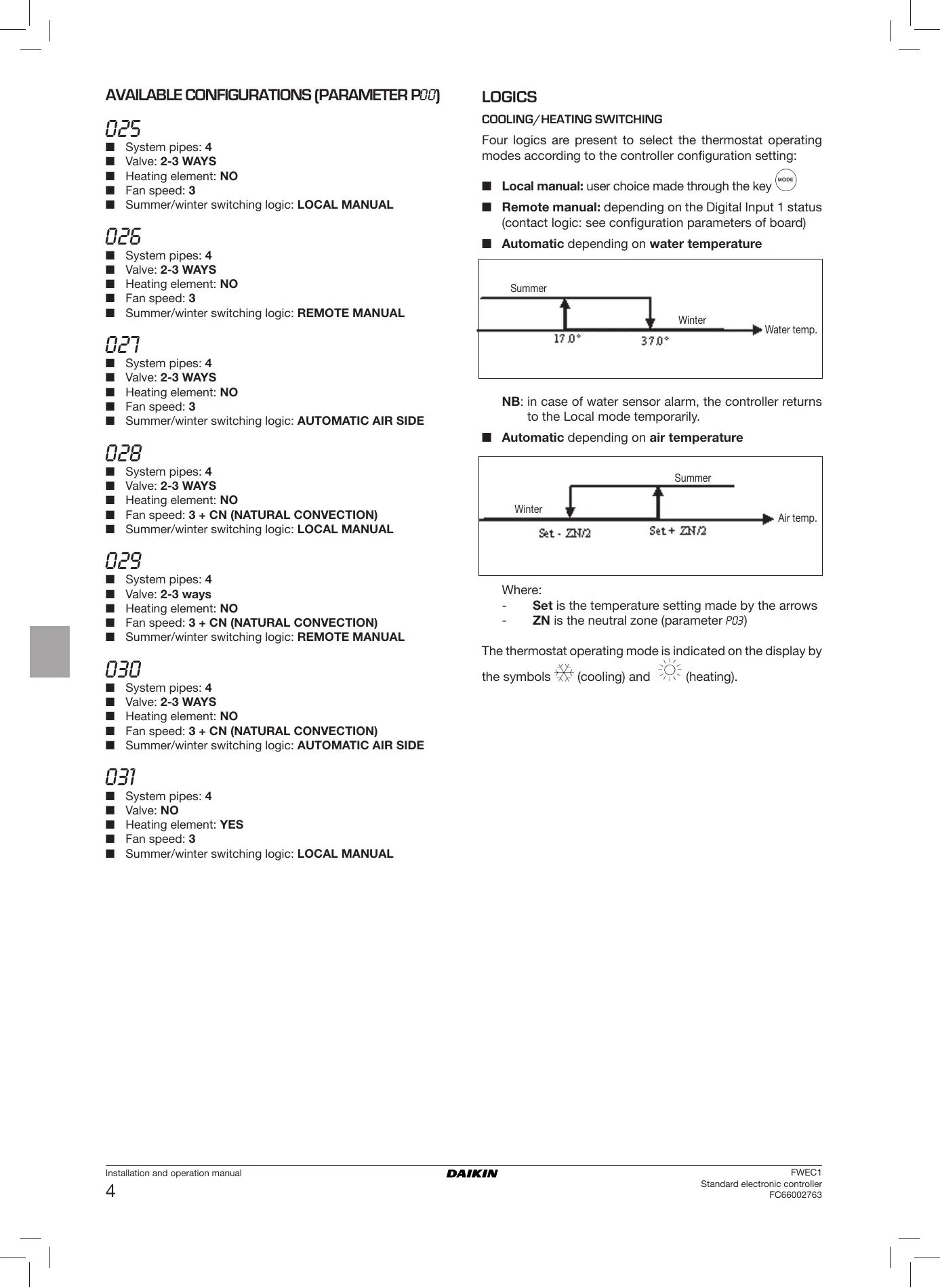
Four logics are present to select the thermostat operating modes according to the controller configuration setting: ■ Local manual: user choice made through the key ■ Remote manual: depending on the Digital Input 1 status (contact logic: see configuration parameters of board) ■ Automatic depending on water temperature Summer Winter Water temp.
System pipes: 4 Valve: 2-3 WAYS Heating element: NO Fan speed: 3 Summer/winter switching logic: AUTOMATIC AIR SIDE
System pipes: 4 Valve: 2-3 WAYS Heating element: NO Fan speed: 3 + CN (NATURAL CONVECTION) Summer/winter switching logic: LOCAL MANUAL NB: in case of water sensor alarm, the controller returns to the Local mode temporarily. ■ Automatic depending on air temperature Summer Winter Air temp.
System pipes: 4 Valve: 2-3 ways Heating element: NO Fan speed: 3 + CN (NATURAL CONVECTION) Summer/winter switching logic: REMOTE MANUAL
System pipes: 4 Valve: 2-3 WAYS Heating element: NO Fan speed: 3 + CN (NATURAL CONVECTION) Summer/winter switching logic: AUTOMATIC AIR SIDE Where: Set is the temperature setting made by the arrows ZN is the neutral zone (parameter P03) The thermostat operating mode is indicated on the display by the symbols (cooling) and (heating).
System pipes: 4 Valve: NO Heating element: YES Fan speed: 3 Summer/winter switching logic: LOCAL MANUAL Installation and operation manual
FWEC1 Standard electronic controller FC66002763 VENTILATION WATER CONTROL The controller can govern 3 or 4-fan speed indoor units The ventilation operation depends on the system water temperature control. Based on the operation mode, different heating or cooling thresholds will be enabled.
OPERATING SPEED SELECTION
Using Fan speeds: key it is possible to select the following COOLING ■ AUTO Automatic fan speed: depending on the set temperature and the room air temperature. With 3-speed configurations: where: 1 = low speed 2 = medium speed 3 = maximum speed Water temp. HEATING Upon a call of the thermostat, the absence of the enabling signal will be indicated on the display by the flashing of the symbol representing the active mode ( Air temp.
The enabling signal is ignored: ■ If the water sensor is not included (P04 = 0) or in alarm status because disconnected ■ In the cooling mode with 4-pipe configurations FORCED OVERRIDES With 4-speed configurations where: sm = extra-low speed 1 = low speed 2 = medium speed 3 = maximum speed The normal fan operating logic will be ignored in particular override situations that may be necessary to ensure correct control of the temperature or the unit’s operation. This may occur: COOLING NB: in case of 4-speed configuration and valve, or 3-speed configuration + CN (natural convection), ventilation in heating mode is shifted by 0.5°C to permit a natural convection phase ■ NO SYMBOLS Speed disabled. Can be selected only in heating mode and with 4-speed configuration or 3-speed configuration + CN (natural convection) only. The indoor unit operates by natural convection only.
in the cooling mode: ■ on-board controller (P01 = 0) and configurations with valve: the minimum speed available will be maintained even once the temperature has been reached. ■ On-board controller and valveless configurations: after every 10 minutes in which the fan remains idle a 2 minute cleaning is carried out at medium speed to enable the air sensor to read the room temperature more correctly. In the heating mode ■ While the heating element is on: the fan is forced to run at medium speed ■ Once the heating element has gone off: a 2 minute postventilation cycle will be run at medium speed. (NB: this cycle will be completed even if the thermostat is switched off or in the event of a changeover to the cooling mode). DISPLAY The display shows the fan status ■ Stb: fan in standby mode ■ On: fan on ■ noF: fan disabled to operate by natural convection only Extra low speed. Can be selected only with 4-speed configuration. It works at extra low speed only. Low speed Medium speed High speed NB In the case of fixed speed, the fan on/off logic will be equivalent to the automatic logic. FWEC1 Standard electronic controller FC66002763 Installation and operation manual
The display shows fan speed (with indication of “automatic” logic if proper) enabled or selected (in case of stand-by fan) Extra low speed HEATING ELEMENT The electrical heating element is a device used to provide support where necessary in the heating mode. SELECTION If provided for in the configuration, the heating element can be Low speed Medium speed selected in the heating mode by pressing the Sel High speed key. ACTIVATION NB: if the active speed is different from the one selected by the user (in the case of a forced override), pressing the button once will cause the latter to be displayed; pressing again will change this setting. Air temp. VALVE The controller can govern 2 or 3-way On/OFF type valves with actuator featuring 230 V. OPENING The valve opening is controlled according to the operating setpoint and air temperature setpoint COOLING If use of the heating element is selected by the user, it will be activated on a call from the thermostat based on the room temperature NB: switching it on will force the fan on as well WATER CONTROL HEATING
Air temp. HEATING Air temp. WATER CONTROL The checking of water temperature to enable valve opening is a function that concerns only configurations with 3-way valves and heating element. In such configurations the water temperature will be checked in the following cases: OFF Water temp. Enabling of the heating element is tied to the water temperature. The related enabling logic is described below The enabling signal will not be given if the water sensor is either not present or disconnected DISPLAY The display will show the following information ■ heating element selected by the user: steadily lit symbol ■ active heating element: flashing symbol ■ Heating with heat element: operation of the heating element will force the fan to switch on; it is therefore necessary to prevent excessively cold water from passing through the unit. Water temp. ■ Post-ventilation due to switching off of the heating element: this function will be maintained until the set time has elapsed, even if the operating mode is changed. During post-ventilation the water temperature enabling signal will coincide with the one seen for fan operation. DISPLAY The active valve indication on the display will be shown by the symbol Installation and operation manual
FWEC1 Standard electronic controller FC66002763 ECONOMY ALARMS The Economy function corrects the setpoint by 2.5°C and forces the fan to run at the minimum available speed to reduce unit operation. This control governs two types of alarms: ■ Serious Alarms cause the forced switching off of the thermostat ■ Non-serious Alarms do not cause the forced switching off of the thermostat, but disable possible critical functions ■ Cooling: setpoint + 2.5°C ■ Heating: setpoint – 2.5°C SERIOUS ALARMS ACTIVATION This function can be activated by pressing the key DISPLAY The Economy function is shown on the display by the symbol ■ Code 01 = error of external air temperature sensor (in case of on-board thermostat) ■ Code 02 = error of internal air temperature sensor (in case of wall mounted thermostat and disconnected external air temperature sensor)
MINIMUM TEMPERATURE CONTROL
This logic makes it possible to keep the room temperature from falling too far when the thermostat is off by forcing the unit into the heating mode if necessary and for the time required. If the heating element is present, it will be used only if it was previously selected as a resource in the heating mode. SELECTION When the thermostat is off, you can select the minimum temperature control by pressing at the same time the keys The same key combination disables this function. ACTIVATION If this control is selected, the unit will switch on when the room temperature falls below 9°C. ■ Code 03 = water sensor error NB: the alarm code is displayed only when the thermostat is switched off. SELF-DIAGNOSIS PROCEDURE This procedure allows you to check whether the individual outputs of the controller function correctly. To run the procedure, follow the directions below. Air temp. When temperature exceeds 10°C the thermostat will resume the Off status. NB: Any Off command from digital input will disable this logic DISPLAY The display shows the following information ■ Switch the thermostat off ■ Push the ■ Minimum temperature control selected: symbol ■ Minimum temperature control enabled: DEFR indication keys at the same time level indication: 1= password entry keys to change the value on the display ■ Use the until arriving at the password for self-diagnosis (030) and press . The following screen will be displayed: ■ Press the button to switch on the various thermostat outputs in sequence. FWEC1 Standard electronic controller FC66002763 Installation and operation manual
Symbol no symbol Actuation Terminals Min. speed N-V1 Med. speed N-V2 Max. speed N-V3 Valve N-Vc Heating element Second valve Extra low speed N-Vh no active outlet The electronic controller outputs can be checked one by one either by observing the respective component (valve, fan..) or verifying whether a voltage of 230 V is present at the corresponding terminals. (after a ■ To exit the self-diagnosis procedure press few minutes the thermostat will automatically exit in any case). ELECTRONIC BOARD (SEE FIGURE 3) Where: CI12 DI1-2 Common DI1 Remote cooling/heating DI2 Remote On/Off
Heater valve/ Heater/extra-low speed
■ For power connections use cable w/ cross section size of 2 mm2 ■ For digital inputs used AWG 24 cable ■ For sensor extensions use AWG 24 shielded cable Installation and operation manual
FWEC1 Standard electronic controller FC66002763 WIRING DIAGRAMS (See Wiring Diagrams enclosed) Configuration table/Diagrams CONFIG. 01-02-03 Unit table/Diagrams UNIT DIAGRAM FWL-M-V FC66002487 [1] FWB UT66000879 [4] FWD FWL-M-V FWB UT66000880 [5] FWD FWL-M-V FWB DIAGRAM
1-2-3-10-11-12-19-20-21-25-26-27 FC66002487 7-8-9-16-17-18 FC66002491 1-2-3-10-11-12-19-20-21-25-26-27 UT66000879 7-8-9-16-17-18-31 UT66000882
1-2-3-10-11-12-19-20-21-25-26-27 UT66000881 7-8-9-16-17-18-31 UT66000884 06/12 3PH 7-8-9-16-17-18-31 UT66000886 16/18 1-2-3-10-11-12-19-20-21-25-26-27 UT66000880 7-8-9-16-17-18-31 UT66000883 16/18 3PH 7-8-9-16-17-18-31 UT66000885 FWL-M-V
UT66000882 [7] FWD UT66000884 [9] UT66000885 [10] FWL-M-V FC66002487 [1] FWB UT66000879 [4] FWD CONFIGURATION 04/12 FC66002491 [2] UT66000886 [11] 10-11-12 TYPE UT66000881 [6] UT66000883 [8] 07-08-09 UNIT EPIMSB6 FC66002493 UT66000880 [5] UT66000881 [6] FWL-M-V FC66002491 [2] FWB UT66000882 [7] UT66000883 [8] 16-17-18 FWD FWEC1 Standard electronic controller FC66002763 Installation and operation manual
WIRING DIAGRAMS Unit table/Diagrams
INSTALLATION OF WALL-MOUNTED
CONTROLLER For wall mounting of the controller it is advisable to use an electric box behind the controller to accommodate the cables.
Electrical connections to be made by installer
Brown NB: Prior to installation, carefully remove the protective film from the display; removal of the film may cause some dark streaks to appear on the display but these will disappear after a few seconds and are not signs of a controller defect. CI12 Digital input common Instructions for installation:
Terminal board ■ Remove the fastening screw of the controller (see figure 4). DI1 Remote Heat/Cool Digital Input DI2 Remote On/Off Digital Input ■ If a 503 electrical enclosure is used, pass the cables through the slot at the bottom of the controller and use the holes provided for fastening. (see figure 5). EXT External auxiliary contact
Circuit breaker (not supplied) ■ Make the electrical connections to the indoor unit terminal block as per the wiring diagram. IPM Circuit board for UTN units ■ Close the controller with the screw provided.
Circuit board to control 4 indoor units
Ground RHC Heating/Cooling remote selecting switch
Water sensor TSA Automatic safety thermostat TSM Safety fuse
Solenoid valve - Cooling
Solenoid valve - Heating VHC Solenoid valve –Cool/Heat.
Heating element relay Installation and operation manual
■ Otherwise, in the wall where you wish to mount the controller, drill holes to match up with the fastening slots (5x8mm) on the base of the controller; pass the cables through the slot on the base and screw it to the wall (previously drilled). (see figure 6). Electrical input 8W Protection fuse 500mA delayed Operating temp. Range 0-50°C Storage temp. Range -10-60°C NO 5A @ 240V (Resistive) Relay insulation: coil-contact distance 8 mm 4000V coil-relay dielectric Max ambient temperature 105°C Connectors 250V 10A Clean contact Digital inputs Closing current 2mA Max. closing resistance 50 Ohm Analog inputs Temperature sensors Power outputs Relay (see above) Temperature sensors NTC sensors 10K Ohm @25°C Range -25-100°C FWEC1 Standard electronic controller FC66002763 FWEC1 Standard electronic controller FWEC1 Standard electronic controller FC66002763 CONFIGURATIONS PRÉVUES (PARAMÈTRE P00)
FWEC1 Standard electronic controller FC66002763
FWEC1 Standard electronic controller FC66002763 VENTILATION ACTIVATION EAU FWEC1 Standard electronic controller FC66002763 ECONOMY ALARMES
ALARMES NON GRAVES
Thermostat OFF Thermostat ON FWEC1 Standard electronic controller FC66002763 FWD FWL-M-V FWB UT66000880 [5] FWD FWL-M-V FWB SCHÉMA
1-2-3-10-11-12-19-20-21-25-26-27 FC66002487 7-8-9-16-17-18 FC66002491 1-2-3-10-11-12-19-20-21-25-26-27 UT66000879 7-8-9-16-17-18-31 UT66000882
1-2-3-10-11-12-19-20-21-25-26-27 UT66000881 7-8-9-16-17-18-31 UT66000884 06/12 3PH 7-8-9-16-17-18-31 UT66000886 16/18 1-2-3-10-11-12-19-20-21-25-26-27 UT66000880 7-8-9-16-17-18-31 UT66000883 16/18 3PH 7-8-9-16-17-18-31 UT66000885 FWL-M-V
UT66000882 [7] FWD UT66000884 [9] UT66000885 [10] FWL-M-V FC66002487 [1] FWB UT66000879 [4] FWD CONFIGURATION 04/12 FC66002491 [2] UT66000886 [11] 10-11-12 TYPE UT66000881 [6] UT66000883 [8] 07-08-09 UNITÉ EPIMSB6 FC66002493 UT66000880 [5] UT66000881 [6] FWL-M-V FC66002491 [2] FWB UT66000882 [7] UT66000883 [8] 16-17-18 FWD FWEC1 Standard electronic controller FC66002763 Fusible (non fourni)
FWEC1 Standard electronic controller FC66002763 FWEC1 Standard electronic controller VORGESEHENE KONFIGURATIONEN (PARAMETER P00)
FWEC1 Standard electronic controller FC66002763
VORGESEHENE KONFIGURATIONEN (PARAMETER P00)
FWEC1 Standard electronic controller FC66002763 LÜFTUNG WASSERSEITIGE FREIGABE FWEC1 Standard electronic controller FC66002763 ECONOMY ALARME FWEC1 Standard electronic controller FC66002763 drücken FWEC1 Standard electronic controller FC66002763 FWD FWL-M-V FWB UT66000880 [5] FWD FWL-M-V FWB SCHALTPLAN
1-2-3-10-11-12-19-20-21-25-26-27 FC66002487 7-8-9-16-17-18 FC66002491 1-2-3-10-11-12-19-20-21-25-26-27 UT66000879 7-8-9-16-17-18-31 UT66000882
1-2-3-10-11-12-19-20-21-25-26-27 UT66000881 7-8-9-16-17-18-31 UT66000884 06/12 3PH 7-8-9-16-17-18-31 UT66000886 16/18 1-2-3-10-11-12-19-20-21-25-26-27 UT66000880 7-8-9-16-17-18-31 UT66000883 16/18 3PH 7-8-9-16-17-18-31 UT66000885 FWL-M-V
UT66000882 [7] FWD UT66000884 [9] UT66000885 [10] FWL-M-V FC66002487 [1] FWB UT66000879 [4] FWD KONFIGURATION 04/12 FC66002491 [2] UT66000886 [11] 10-11-12 TYP UT66000881 [6] UT66000883 [8] 07-08-09 GERÄT EPIMSB6 FC66002493 UT66000880 [5] UT66000881 [6] FWL-M-V FC66002491 [2] FWB UT66000882 [7] UT66000883 [8] 16-17-18 FWD FWEC1 Standard electronic controller FC66002763 Digitaleingang On/Off fernbed. EXT Externer Hilfskontakt
Normal Open 5 A @ 240 V (resistiv) Relais Steckverbinder FWEC1 Standard electronic controller FC66002763 FWEC1 Standard electronic controller
CARACTERÍSTICAS GENERALES
MONITOR LCD (VÉASE FIGURA 1) (1) Temperatura ambiente (2) Estado termostato/ventilador (3) Temperatura programada AUTO FWEC1 Standard electronic controller FC66002763 TECLADO (VÉASE FIGURA 2) FWEC1 Standard electronic controller FC66002763 FWEC1 Standard electronic controller FC66002763
FWEC1 Standard electronic controller FC66002763 VENTILACIÓN FWEC1 Standard electronic controller FC66002763 ECONOMY ALARMAS FWEC1 Standard electronic controller FC66002763 FWD FWL-M-V FWB UT66000880 [5] FWD FWL-M-V FWB ESQUEMA
1-2-3-10-11-12-19-20-21-25-26-27 FC66002487 7-8-9-16-17-18 FC66002491 1-2-3-10-11-12-19-20-21-25-26-27 UT66000879 7-8-9-16-17-18-31 UT66000882
1-2-3-10-11-12-19-20-21-25-26-27 UT66000881 7-8-9-16-17-18-31 UT66000884 06/12 3PH 7-8-9-16-17-18-31 UT66000886 16/18 1-2-3-10-11-12-19-20-21-25-26-27 UT66000880 7-8-9-16-17-18-31 UT66000883 16/18 3PH 7-8-9-16-17-18-31 UT66000885 FWL-M-V
UT66000882 [7] FWD UT66000884 [9] UT66000885 [10] FWL-M-V FC66002487 [1] FWB UT66000879 [4] FWD CONFIGURACIÓN 04/12 FC66002491 [2] UT66000886 [11] 10-11-12 TIPO UT66000881 [6] UT66000883 [8] 07-08-09 UNIDAD EPIMSB6 FC66002493 UT66000880 [5] UT66000881 [6] FWL-M-V FC66002491 [2] FWB UT66000882 [7] UT66000883 [8] 16-17-18 FWD FWEC1 Standard electronic controller FC66002763 Entrada digital Refr./Calef. remoto DI2 Entrada digital On/Off remoto EXT Selector remoto Calef./Refrig.
Resistencia Eléctrica
Sondas NTC 10 K Ohmios @25 °C Rango -25-100 °C FWEC1 Standard electronic controller FC66002763 FWEC1 Standard electronic controller MONITOR LCD (VER FIGURA 1) (1) Temperatura ambiente (2) FWEC1 Standard electronic controller FC66002763 FWEC1 Standard electronic controller FC66002763 FWEC1 Standard electronic controller FC66002763
FWEC1 Standard electronic controller FC66002763 VENTILAÇÃO FWEC1 Standard electronic controller FC66002763 ECONOMY ALARMES FWEC1 Standard electronic controller FC66002763 FWD FWL-M-V FWB UT66000880 [5] FWEC1 Standard electronic controller FC66002763 Microinterruptor do Flap
Terra Temp. Funcionamento Amplitude 0-50°C RHC Selector remoto Aquec./Refrig. Temp. Armazenagem Amplitude -10-60°C
Resistência Eléctrica
FWEC1 Standard electronic controller FC66002763 FWEC1 LCD DISPLAY (ZIE AFBEELDING 1) (1) Omgevingstemperatuur (2) Standard electronic controller
TOETSENBORD (ZIE AFBEELDING 2) FWEC1 Standard electronic controller FC66002763 FWEC1 Standard electronic controller FC66002763
FWEC1 Standard electronic controller FC66002763
VRIJGAVE VAN WATER
FWEC1 Standard electronic controller FC66002763
FWEC1 Standard electronic controller FC66002763 ECONOMY ALARMEN ELEKTRONISCHE KAART (ZIE AFBEELDING 3) Activering N-Vh FWEC1 Standard electronic controller FC66002763 FWD FWL-M-V FWB UT66000880 [5] FWD FWL-M-V FWB SCHEMA
1-2-3-10-11-12-19-20-21-25-26-27 FC66002487 7-8-9-16-17-18 FC66002491 1-2-3-10-11-12-19-20-21-25-26-27 UT66000879 7-8-9-16-17-18-31 UT66000882
1-2-3-10-11-12-19-20-21-25-26-27 UT66000881 7-8-9-16-17-18-31 UT66000884 06/12 3PH 7-8-9-16-17-18-31 UT66000886 16/18 1-2-3-10-11-12-19-20-21-25-26-27 UT66000880 7-8-9-16-17-18-31 UT66000883 16/18 3PH 7-8-9-16-17-18-31 UT66000885 FWL-M-V
UT66000882 [7] FWD UT66000884 [9] UT66000885 [10] FWL-M-V FC66002487 [1] FWB UT66000879 [4] FWD CONFIGURATIE 04/12 FC66002491 [2] UT66000886 [11] 10-11-12 TYPE UT66000881 [6] UT66000883 [8] 07-08-09 UNIT EPIMSB6 FC66002493 UT66000880 [5] UT66000881 [6] FWL-M-V FC66002491 [2] FWB UT66000882 [7] UT66000883 [8] 16-17-18 FWD FWEC1 Standard electronic controller FC66002763 Range -10-60°C Normal Open 5A @ 240V (Resistief) Relais Meter NTC 10K Ohm @25°C Range -25-100°C FWEC1 Standard electronic controller FC66002763 FWEC1 Standard electronic controller FWEC1 Standard electronic controller FC66002763 FWEC1 Standard electronic controller FC66002763 FWEC1 Standard electronic controller FC66002763
FWEC1 Standard electronic controller FC66002763 VENTILLÁCIÓ FWEC1 Standard electronic controller FC66002763 ECONOMY
VÉSZJELZÉSEK
FWEC1 Standard electronic controller FC66002763 FWEC1 Standard electronic controller FC66002763
ELEKTROMOS KAPCSOLÁSI RAJZOK
FWEC1 Standard electronic controller FC66002763 FWEC1 Standard electronic controller FWEC1 Standard electronic controller FC66002763 FWEC1 Standard electronic controller FC66002763 FWEC1 Standard electronic controller FC66002763
FWEC1 Standard electronic controller FC66002763 FWEC1 Standard electronic controller FC66002763 FWEC1 Standard electronic controller FC66002763
FWEC1 Standard electronic controller FC66002763 FWEC1 Standard electronic controller FC66002763 FWEC1 Standard electronic controller FC66002763 Standard electronic controller FWEC1
FWEC1 Standard electronic controller FC66002763
■ $!* ,$%'& (OFF) FWEC1 Standard electronic controller FC66002763 FWEC1 Standard electronic controller FC66002763 FWEC1 Standard electronic controller FC66002763
FWEC1 Standard electronic controller FC66002763 Economy &'*-34/0 ■ $!* ,$%'& (OFF) FWEC1 Standard electronic controller FC66002763 . %)G &
FWEC1 Standard electronic controller FC66002763 FWEC1 Standard electronic controller FC66002763
63784607- +0-4-//-8- $"& Flap
+"% ,$%'& ) Temp. Stoccaggio Range -10-60°C TSM Sonde NTC 10K Ohm @25°C Range -25-100°C FWEC1 Standard electronic controller FC66002763 NOTES FC66002487
FWL-M-V FC66002493 FWL-M-V FWB EPIMSB6
FWD UT66000880 EPIB6