Drumfit Indoor Pulseride - Fitness Equipment CECOTEC - Free user manual and instructions
Find the device manual for free Drumfit Indoor Pulseride CECOTEC in PDF.


| Brand | Cecotec |
| Model | Drumfit Indoor Pulseride |
| Product type | Stationary exercise bike |
| Use | Indoor, domestic use |
| Maximum user weight | 135 kg |
| Equipment class | Class HC |
| Power supply | Batteries for the monitor (not included) |
| Display | LCD monitor with time, speed, distance, calories and heart rate |
| Resistance | Friction braking system on flywheel |
| Flywheel | Yes, with smooth rotation |
| Heart rate sensors | Yes, on the handles |
| Connectivity | Wi-Fi and smartphone app |
| Adjustments | Seat and handlebars adjustable in height |
| Pedals | With adjustable toe clips |
| Emergency brake | Yes, safety brake |
| Transport | Wheels for moving |
| Dimensions (est.) | 120 x 55 x 115 cm |
| Device weight (est.) | 28 kg |
| Maintenance | Clean with a damp cloth, regularly check screws and nuts |
| Safety | Keep out of reach of children, do not use outdoors |
| Spare parts | Available through Cecotec after-sales service |
| Warranty | Statutory warranty of conformity |
Frequently Asked Questions - Drumfit Indoor Pulseride CECOTEC
User questions about Drumfit Indoor Pulseride CECOTEC
0 question about this device. Answer the ones you know or ask your own.
Ask a new question about this device
Download the instructions for your Fitness Equipment in PDF format for free! Find your manual Drumfit Indoor Pulseride - CECOTEC and take your electronic device back in hand. On this page are published all the documents necessary for the use of your device. Drumfit Indoor Pulseride by CECOTEC.
USER MANUAL Drumfit Indoor Pulseride CECOTEC
DRUMFIT
Safety instructions 9
-
Parts and components 77
-
Before use 81
-
Assembly 82
-
Operation 85
-
Exercise guidelines 88
-
Wi-Fi connectivity and mobile App 88
-
Cleaning and maintenance 89
-
Troubleshooting 89
-
Technical specifications 90
-
Recycling of electrical and electronic equipment 91
-
Technical support and warranty 91
-
Information on data stored by connected products in accordance with Regulation (EU)
2023/2854 ("Data Regulation") 91
-
Copyright 92
-
Simplified EU Declaration of Conformity 92
SOMMAIRE
EU01_122813 - Drumfit indoor PulseRide
EN · The coding in this manual is generic and applies to all code variants of the appliance.
Please read these instructions carefully before using the appliance. Keep this instruction manual for future reference or new users.
- Read the entire manual before assembling and using the machine. The product will only be safe if it is properly assembled, cared for and used correctly. It is your responsibility to make sure every user is informed about the warnings and precautions stated in this instruction manual.
- Before starting a training session, it is recommended that you consult your doctor if you have any adverse health or physical condition that may pose a risk to your safety or make it difficult to use the exercise bike properly. Your doctor's advice is essential if you are taking medication that affects your heart rate, blood pressure, or cholesterol level.
- Be aware of your body signals. Incorrect or excessive exercise can deteriorate your health. Stop exercising if you experience any of the following symptoms: pain, tightness in your chest, irregular heartbeat, extreme shortness of breath, dizziness, or nausea. If you experience any of these conditions, you should consult your doctor before continuing with your training.
- This machine can be used by children aged 14 years and above and persons with reduced physical, sensory, or mental capabilities or lack of experience and knowledge if they have been given supervision or instruction concerning the use of the machine in a safe way and understand the hazards involved. Children must not play with the appliance. Cleaning and user maintenance must not be carried out by children without supervision.
-
Keep children and animals away from the assembling area, as small parts could cause risk of suffocation if swallowed.
-
Keep children and pets away from the machine. Do not allow children to use it and/or play with the machine. It is designed for adults only.
- Use the exercise bike on a solid, even surface with a protective cover for your floor or carpet.
- Ensure all screws and nuts are properly tightened before using the machine.
- The safety level of the machine can only be ensured through regular examination for damage or signs of wear and tear.
- Use the machine as indicated in this instruction manual. If you find any defective component while assembling or checking the machine, or if you hear any unusual noise coming from the equipment during use, stop using it. Do not use the equipment until the problem has been solved.
- Make sure you have enough space to lay out the parts before starting. Leave a free space of at least 0.6 m in front of all access areas of the machine in case of emergency. You can share the access areas with other machine nearby. Always ensure there are not any objects blocking the entrance and exit of the machine.

- Wear suitable clothing while using the machine. Avoid wearing loose clothing which may get caught in the equipment.
- WARNING: this training machine is not suitable for high-precision purposes. This equipment is HC class.
- WARNING: this machine operates by means of a flywheel. Be careful when in motion and ensure that it completely stops before getting down, as the inertia of the flywheel and pedals could cause injury to yourself or others.
- Maximum user weight: 135 kg.
- It is not recommended for outdoor use. This machine is designed for indoor use.
- This machine is designed for domestic use only and is not intended for bars, restaurants, farmhouses, hotels, motels, and offices.
- The machine is not suitable for therapeutic use.
- Care must be taken when lifting or moving the equipment so as not to injure your back.
- WARNING: the heart rate sensors may be inaccurate, as it is not a medical device. Sensors can give you estimated heart rate information. If you feel any discomfort, stop exercising immediately. It may be dangerous for your health. If it persists, go immediately to the nearest medical centre.
- If repairs are required, please consult your supplier for further information or contact Cecotec Customer Service.
- If any parts protrude from the machine, they may interfere with the user's movement.
Instructions on batteries
- Do not burn or expose the batteries to high temperatures, as they may explode.
- Leaks from the batteries can occur under extreme conditions. Do not touch any liquid that leaks from the batteries. If the liquid comes into contact with skin, wash immediately with soap and water. If the liquid gets into the eyes, rinse them immediately with clean water for at least 10 minutes and seek medical attention. Wear gloves to handle the battery and dispose of it immediately in accordance with local regulations.
- Avoid contact between the batteries and small metal objects such as paper clips, coins, keys, nails, or screws.
- Do not tamper with the batteries in any way.
- The batteries must be removed for safe disposal of the machine.
- Keep the batteries out of the reach of children when there is a risk of ingestion.
- Battery ingestion can cause burns, soft-tissue perforation, and death. It can cause severe burns within two hours of the ingestion.
- In case of battery ingestion, please seek medical help immediately.
- The batteries' power supply terminals must not be short-circuited.
- If the machine is to be stored for a long period of time, it is advisable to remove the batteries.
- The batteries must be inserted in the correct position. Check polarity when replacing them.
INSTRUCTIONS DE SÉCURITÉ
A = Perilla "L" (27) ×1
Procedimiento
D = Llave Allen 5 mm (39) ×1
Procedimiento
Paso 6: Montar pedales
Figura 8.
Procedimiento
https://cecotec.es/es/information/declaration-of-conformity
1. PARTS AND COMPONENTS
Fig. 1
| No. | Name | Specification | Qty. |
| 1 | Main frame | Welded assembly | 1 |
| 2 | Handlebar | Welded assembly | 1 |
| 3 | Magnetic bracket | Welded assembly | 1 |
| 4 | Saddle post | Welded assembly | 1 |
| 5 | Front stabiliser | Welded assembly | 1 |
| 6 | Rear stabiliser | Welded assembly | 1 |
| 7 | Junction plate assembly | Welded assembly | 1 |
| 8 | Brake plate assembly | Welded assembly | 1 |
| 9 | Motor bracket | δ 2.5 | 1 |
| 10 | Tension knob plate | δ 1.0 | 1 |
| 11 | Adjustment bracket | Welded assembly | 1 |
| 12 | Connecting rod assembly | Welded assembly | 1 |
| 13 | Handlebar post | Welded assembly | 1 |
| 14 | Vertical saddle post | Welded assembly | 1 |
| 15 | Flywheel mounting plate | δ 2.5 | 2 |
| 16 | Washer | δ 2 | 1 |
| 17 | Flywheel | 18 kg | 1 |
| 18 | Electronic cable | 535×70× 1.2 | 1 |
| 19 | Flywheel shaft | 17×149 | 1 |
| 20 | Metal tube | 30× 25.05×14 | 1 |
| 21 | Left crank | 170 “L”, 9/16 | 1 |
| 22 | Right crank | 170 “R”, 9/16 | 1 |
| 23 | Magnet | 25×10×5 | 10 |
| 24 | Tension spring | 40× 8× 0.8 | 2 |
| 25 | Pressure pulley chuck | 20×42.5, M10 | 1 |
| 26 | “L” type spring knob | M16×40 | 1 |
| 27 | “L” knob | M10×45 | 1 |
| 28 | Belt pulley | ∅240×21, 5PK | 1 |
| 29 | Shaft | ∅25×225 | 1 |
| 30 | Aluminium grips | 80×16×10 | 2 |
| 31 | Stepped shaft | ∅8×40.5 | 1 |
| 32 | Long shaft | ∅5×46 | 1 |
| 33 | Fixed shaft | ∅8×16 | 1 |
| 34 | Short shaft | ∅5×23 | 1 |
| 35 | Spacer | ∅8×∅5.2×20 | 1 |
| 36 | Mounting frame | 65×27.5×23.5 | 1 |
| 37 | Spring | ∅8×∅0.8×50 | 1 |
| 38 | Allen key 6# | 6# (86×35) | 1 |
| 39 | Allen key | 5 mm | 1 |
| 40 | Spanner | 132×28/33×16, S=13/15 (GB) | 1 |
| 41 | Bearing 6005 | 6005ZZ | 2 |
| 42 | Bearing 6203 | 6203RS | 3 |
| 43 | Bearing 608 | 608ZZ | 4 |
| 44 | Left cover | — | 1 |
| 45 | Right cover | — | 1 |
| 46 | Front cover | 31×61.5 | 1 |
| 47 | Rear cover | 53.5×30 | 1 |
| 48 | Decorative cover | — | 1 |
| 49 | Front saddle tube bush | 260×38.3×36.5 | 1 |
| 50 | Rear saddle tube bush | 300×56.1×36.5 | 1 |
| 51 | Console upper cover | 319×100×126 | 1 |
| 52 | Console lower cover | 319×100×140 | 1 |
| 53 | Brake knob | — | 1 |
| 54 | Transport wheel | ∅69×26 | 2 |
| 55 | Pedal | JD-304V M20×1.5 | 1 |
| 56 | End cap | ∅52×43; M8×25 | 4 |
| 57 | Saddle | 270×210 | 1 |
| 58 | Brake pad (leather) | 40×40×T5.5 | 1 |
| 59 | Belt | 5PK, 1400 mm (55 in) | 1 |
| 60 | Small belt | 2PJ, 384 mm (150) | 1 |
| 61 | Oval end cap | 100×50×2 | 4 |
| 62 | Plastic pulley | ∅43×∅34×24 | 1 |
| 63 | Small bush | ∅18×∅10×10 | 2 |
| 64 | U-shaped grip | 59.6×57.5×20.7 | 1 |
| 65 | Plastic sleeve | 61.5×31 | 4 |
| 66 | Small belt pulley | ∅85×∅50×11, 2PJ | 1 |
| 67 | End cap | 50×25×1.5 | 2 |
| 68 | Crank end cap | ∅28×6.5 | 2 |
| 69 | Insulating column | ∅6×∅3×4 | 4 |
| 70 | Saddle slider assembly | 172.8×71.6×26.3 | 1 |
| 71 | Console | RBT2035 | 1 |
| 72 | Tension knob | 32 levels | 1 |
| 73 | Pulse sensor | 33.5×27 | 1 |
| 74 | M12 hex flange nut | M12×1.25 | 2 |
| 75 | Hex flange nut | M12×1.25 (∅22×17×D8) | 2 |
| 76 | M10 hex flange nut | M10 S14 H8 | 1 |
| 77 | M8 self-locking nut | GB/T 889.1-2000 M8 | 7 |
| 78 | M5 self-locking nut | GB/T 889.1-2000 M5 | 1 |
| 79 | M4 self-locking nut | GB/T 889.1-2000 M4 | 2 |
| 80 | Screw (M6×10) | M6×10 | 7 |
| 81 | Screw (M6×35) | M6×35 | 1 |
| 82 | Screw (M6×12) | M6×12 | 4 |
| 83 | Screw (M6×50) | M6×50 | 1 |
| 84 | Hex head screw | GB/T 5780-2000 M8×40 | 2 |
| 85 | M8×20 Allen screw | GB/T 70.1-2000 M8×20 | 4 |
| 86 | M4×5 Allen screw | GB/T 70.2-2000 M4×5 | 3 |
| 87 | M8×10 Allen screw | GB/T 70.1-2000 M8×10 | 2 |
| 88 | M8×45 Allen screw | GB/T 70.2-2000 M8×45 | 1 |
| 89 | M6 hex nut | GB/T 41-2000 M6 | 2 |
| 90 | Phillips screw | ST4.2×16 | 4 |
| 91 | Round screw | M50×1.5 | 1 |
| 92 | M4×8 cross-head screws | M4×8 | 6 |
| 93 | M8×18 Allen screw | M8×18 | 4 |
| 94 | M5×12 cross-head screws | M5×12 | 10 |
| 95 | M4×15 cross-head screws | M4×15 | 2 |
| 96 | Phillips screw | ST4.2×16 | 5 |
| 97 | Phillips screw | GB845-1985 ST2.9×16 | 5 |
| 98 | Phillips screw | GB/T 845-1985 ST2.9×13 | 4 |
| 99 | Phillips screw | ST4.2×16 | 13 |
| 100 | Phillips screw | ST2.9×9.5 | 9 |
| 101 | Phillips screw | ST2.9×6.5 | 6 |
| 102 | Phillips screw | ST4.2×25 | 1 |
| 103 | Phillips screw | M4×12 | 4 |
| 104 | Curved washer | GB/T 955-1987 (d1=27, D=34, s=0.3) | 1 |
| 105 | Curved washer | GB/T 955-1987 (d1=17, D=23, s=0.3) | 1 |
| 106 | Flat washer 5 | GB/T 95-2002 5 | 1 |
| 107 | Flat washer 6 | GB/T 95-2002 6 | 3 |
| 108 | Flat washer 6 | GB/T 95-2002 6 | 4 |
| 109 | Flat washer 8 | GB/T 95-2002 8 | 4 |
| 110 | Circlip ∅17 | GB 894.1 ∅17 | 2 |
| 111 | Circlip ∅25 | GB 894.1 ∅25 | 1 |
| 112 | Circlip ∅10 | GB 894.1 ∅10 | 1 |
| 113 | Spring washer 6 | GB/T 859-1987 6 | 4 |
| 114 | Washer 6 | 6 | 1 |
| 115 | Washer 10 | 10 | 1 |
| 116 | Flat washer 4 | GB/T 95-2002 4 | 4 |
Mounting kit
Fig. 2
| Letter | No. | Name (official nomenclature) | Specification | Qty. | Unit | Remarks |
| A | 38 | Allen key 6# | 6# (86×35) | 1 | pcs | For M8 screws. |
| B | 85 | M8×20 Allen screw | GB/T 70.1-2000 M8×20 | 4 | pcs | Listed as “4 SET” in original; see Remarks. |
| C | 109 | Flat washer 8 | GB/T 95-2002 8 | 4 | pcs | For M8. |
| D | 39 | Allen key | 5 mm | 1 | pcs | For M6 screws. |
| E | 82 | Screw (M6×12) | M6×12 | 4 | pcs | Shown as “hex screw” in figures; confirm Allen head. |
| F | 113 | Spring washer 6 | GB/T 859-1987 6 | 4 | pcs | For M6. |
| G | 108 | Flat washer 6 | GB/T 95-2002 6 | 4 | pcs | For M6. |
| H | 40 | Spanner | 132×28/33×16, S=13/15 (GB) | 1 | pcs | Double-ended spanner S13/S15 (pedals/nuts). |
Note:
The graphics in this manual are schematic representations and may not exactly match the product.
2. BEFORE USE
- This appliance comes in a packaging designed to protect it during transport. Remove the appliance from its box. You can keep the original box and other packaging materials in a safe place to prevent damage to the appliance if you need to transport it in the future. If you wish to dispose of the original packaging, make sure all items are recycled properly.
ENGLISH
- Check that all parts and components are included and in good condition. If any of them are missing or damaged, please contact Cecotec's Official Technical Support Service immediately.
Box content:
- Product
- Instruction manual
- Do not remove the product's serial number in order to keep proper traceability if technical assistance is required.
3. ASSEMBLY
Step 1: Front and rear stabiliser assembly
Fig. 3
A = Flat washer 8 (1 0 9) × 4 B = M 8 × 2 0 (8 5) × 4 Allen screw C = 6 # Allen wrench (3 8) × 1
Procedure
- Place the front stabiliser (5) under the main frame (1). Then align the holes and insert 2× B with 2× A. Tighten with C.
- Place the rear stabiliser (6) under the main frame (1). Then align the holes and insert 2 × B with 2 × A . Tighten with C.
Brief note: The stabilizer with wheels is the front one.
Step 2: Remove the protective tube
Fig. 4
A = Knob L (2 7) × 1
Procedure
- Loosen the "L" knob (27; A) by turning it anticlockwise and pull to release the pin.
- Pull the protective tube upwards and remove it.
Note: Keep the tube for possible transport or storage.
Step 3: Mounting the handlebar
Fig. 5
A = Screw M6 × 1 2 (8 2) × 4 B = Spring washer 6 (113) × 4 C = Flat washer 6 (108) × 4 D = Allen wrench 5 mm (3 9) × 1
Procedure
- Insert the Electronic Cable (18) inside the Handlebar Post (13) and pull it out from the top.
- Seat the Handlebar (2) on the Handlebar Post (13). Place 4× C (against the part) + 4× B (under the head) + 4× A. Tighten with D.
Note: Avoid pinching the cable. Start threading by hand.
Step 4: Assembling the handlebar post
Fig. 6.
Procedure
- Connect the console cables.
- Loosen and pull Knob «L» to release the pin.
- Insert the Handlebar Post into the Main Frame to the desired height.
- Release and tighten Knob «L» to lock.
Note: Respect the minimum insertion mark. Make sure that the cables are free.
Step 5: Mounting the saddle
Fig. 7.
Procedure
- Place the saddle (57) on the saddle slider assembly (70) in a horizontal position.
- Center the rails and tighten the assembly fasteners with the wrench until locked.
Note: Verify leveling and firm fastening.
Step 6: Mounting pedals
Fig. 8.
Procedure
- Screw the L pedal (55) onto the left crank (21) by hand in an anticlockwise direction. Then tighten with the spanner.
- Screw the R pedal (55) onto the right crank (22) by hand in a clockwise direction. Then tighten with the spanner.
Note: Check the «L» and «R» markings before threading the pedals. Always start by hand.
Settings
Saddle height adjustment (57) / Vertical saddle post (14)
Fig. 9.
- To raise: lift the saddle (57) upwards. The mechanism will move with clicks. When it reaches the right height, release it so that it locks into place.
- To lower: with one hand, lift the lever beneath the saddle (saddle slider assembly mechanism, 70) and, with the other hand, press the saddle downwards. Release the handle to set the height.
ENGLISH
Fore/aft saddle adjustment:
Fig. 9.
- Loosen the «L» knob (27).
- Slide the saddle slider assembly (70) forwards (towards the handlebar, 2) or backwards to the desired position.
- Retighten the «L» knob (27).
Insertion limit
- The vertical seat post (14) must not exceed the minimum insertion «STOP» mark.
Handlebar post height
Fig. 10.
Procedure
- Loosen the «L» knob (27) and pull it to release the pin.
- Slide the Handlebar Post (13) up or down inside the Main Frame (1) to the desired height, aligning the holes.
- Release and tighten Knob «L» (27) to lock the position.
Warning:
- Do not exceed the minimum insertion «STOP» mark on the handle post (13).
Levelling
Fig. 11.
Procedure
- Place the bicycle on a flat surface.
- Rotate each Stop (56) until it rests fully on the floor and eliminates rocking.
- Check that the four Stops (56) support the weight equally.
Brief Note
- «Low / high» in the drawing indicates shortening / lengthening of the stop. Adjust alternately between front (5) and rear (6) stabilizers.
Emergency stop
Emergency stop instructions
Fig. 12.
- Push the Brake Knob (53) down to increase the resistance and quickly stop the Flywheel (17).
- When the «click» is heard, the flywheel (17) is locked.
- To unlock, pull the Brake Knob (53) upwards.
After each use, press the Brake Knob (53) until it «clicks» to lock the Flywheel (17) and prevent children from spinning it.
Transport
Fig. 14.
Procedure
- Hold the front end of the Handlebar (2).
- Tilt the bicycle until the Transport Wheels (54) of the Front Stabilizer (5) are fully supported.
- Move the machine by rolling it to the desired position.
- Lower slowly until both stabilizers contact the ground.
Brief Note
- Before moving, lock the handwheel with the Brake Knob (53). Use only on smooth surfaces. Do not carry up/down stairs or move while user is seated on the bike.
4. OPERATION
Control panel
| No. | NAME | ICON | SPECIFICATION |
| 1 | TIME |  | 00:00-99:59 (mm:ss) |
| 2 | SPEED |  | 0.0–99.9 km/h [or mph if the console allows unit change] |
| 3 | DISTANCE |  | 0.00–99.9 km |
| 4 | CAL (Calories) |  | 0-9999 kcal |
| 5 | WATT (Power) |  | 0–999 W |
| 6 | PULSE |  | 0–200 bpm |
| 7 | LEVEL |  | 01–16 |
| 8 | BLUETOOTH |  | The icon lights up when there is a Bluetooth connection |
Function buttons
The center of the knob is the START/STOP button.
- With the console stopped, press briefly to start counting.
- When the console is activated, press briefly to pause. When paused, press briefly to resume. Press and hold for about 3 seconds to reset all data to zero.
Knob rotation:
- Turn the knob clockwise: during workout, increases resistance level. In standby mode, selects automatic programmes P1–P9–10–11–12.
- Turn the knob anticlockwise: during workout, reduces resistance level. In standby mode, selects automatic programmes P1–P9–10–11–12.
Note: after powering on or restarting, the first screen is standby mode.
Automatic programmes (P1-P12)
- The system changes segments every 60 seconds. Each program has 16 segments (total duration ≈ 16 min).
- The numbers indicate the target level of resistance in each segment.
| 1 | 2 | 3 | 4 | 5 | 6 | 7 | 8 | 9 | 10 | 11 | 12 | 13 | 14 | 15 | 16 | |
| P1 | 10 | 12 | 16 | 8 | 2 | 10 | 16 | 10 | 2 | 18 | 10 | 4 | 12 | 8 | 12 | 6 |
| P2 | 10 | 14 | 16 | 10 | 5 | 10 | 20 | 6 | 16 | 12 | 5 | 20 | 12 | 8 | 14 | 6 |
| P3 | 10 | 18 | 6 | 18 | 3 | 16 | 3 | 10 | 22 | 6 | 18 | 6 | 20 | 6 | 16 | 6 |
| P4 | 5 | 6 | 6 | 6 | 9 | 9 | 9 | 12 | 12 | 12 | 15 | 15 | 15 | 9 | 9 | 9 |
| P5 | 5 | 6 | 6 | 6 | 9 | 9 | 9 | 12 | 12 | 12 | 15 | 15 | 15 | 12 | 12 | 12 |
| P6 | 5 | 6 | 7 | 8 | 7 | 6 | 6 | 6 | 9 | 9 | 9 | 9 | 9 | 9 | 12 | 12 |
| P7 | 5 | 7 | 9 | 9 | 9 | 8 | 13 | 15 | 15 | 15 | 3 | 3 | 9 | 9 | 9 | 15 |
| P8 | 5 | 8 | 6 | 6 | 9 | 9 | 9 | 12 | 12 | 12 | 15 | 15 | 15 | 6 | 6 | 6 |
| P9 | 5 | 9 | 6 | 6 | 8 | 8 | 9 | 9 | 9 | 12 | 12 | 12 | 9 | 9 | 9 | 12 |
| 10 | 5 | 6 | 9 | 9 | 9 | 12 | 12 | 12 | 12 | 12 | 12 | 12 | 12 | 9 | 9 | 9 |
| 11 | 5 | 6 | 9 | 9 | 9 | 9 | 9 | 9 | 3 | 3 | 3 | 3 | 15 | 15 | 15 | 15 |
| 12 | 5 | 6 | 15 | 15 | 15 | 13 | 12 | 15 | 15 | 15 | 10 | 10 | 15 | 15 | 15 | 5 |
Algorithm
- 60 RPM corresponds to 21.5 km/h.
- If there is no cadence signal, calories and distance are not counted.
Sleep and automatic shut-off
- No pedalling for 60 seconds: the console automatically pauses.
- No pedalling for 2 minutes: the console turns off and enters sleep mode.
- Reactivation: start pedalling to activate the console.
Heart rate cable
- Gently place your fingertips on the Pulse Sensor (73). Keep your hands still.
- Do not press hard on the sensor: excessive pressure reduces blood flow and worsens the reading.
- Pulse data are indicative and do not constitute medical information.
Note:
- The system integrates a generator and a battery. If the energy generated by pedalling is insufficient (e.g. at low cadence for a long time), the battery powers the console.
- When the battery is depleted, the display may reset or flicker.
ENGLISH
- Charging: connect a TYPE-C/USB-C charger to the console port. The equipment can be used normally while charging.
- First use: due to transport regulations, the battery may arrive with a low charge. Charge 4-5 hours before first use.
- Prolonged inactivity: after a long period of non-use, charge for 4-5 hours before using the product again.
5. EXERCISE GUIDELINES
A proper workout should consist of the following phases:
- Warm-up: 5-10 minutes of stretching and low-intensity exercise. A proper warm-up increases body temperature, heart rate and circulation, preparing you for exercise. Fig. 14
- Training: 20–30 minutes of exercise. (Note: during the first weeks of training, do not maintain a high heart rate for more than 20 minutes). Fig. 15
- Cool-down: 5-10 minutes of stretching. This increases flexibility and helps prevent post-exercise injuries. Fig. 14
6. WI-FI CONNECTIVITY AND MOBILE APP
a. Kinomap
Search, download and install the Kinomap app from the Apple Store or Google Play depending on your mobile phone system.
1) Access the APP and click on the "More" page.
2) Select the «Add new training machine» option.
3) Select the type of equipment «exercise bike».
4) Then click on the device or on «Cecotec» to pair the machine.
5) Look for videos to start the training.
b. Zwift
Search, download and install the Zswift APP from the Apple Store or Google Play depending on your mobile phone system.
1) Create an account and log in to the APP.
2) Activate the product sensors and Bluetooth on your phone or tablet.
3) Select the type of equipment «exercise bike».
4) Then click on the power or speed source icon.
5) Search route to start training.
- Please note that it is not possible to include a complete application guide in this manual, as it is a free third-party application and is updated continuously.
- For more information about the app, please refer to the instructions found within the specific application or in the Google PlayStore or AppStore.
7. CLEANING AND MAINTENANCE
- Periodically lubricate moving parts to prevent premature wear.
- Inspect and tighten all parts before use. If any part is damaged, replace it immediately and do not use the machine until it is in perfect condition.
- Clean the machine with a slightly damp cloth and non-abrasive detergent. Do not use solvents.
- Do not try to repair the machine by yourself. If you experience any difficulties with assembly, operation or believe parts are missing, please contact your dealer or Cecotec's Official Technical Support Service.
Warning:
The frequency of cleaning and maintenance depends on usage frequency and intensity.
8. TROUBLESHOOTING
| Problem | Possible causes | Solution |
| No display | The controller/driver has no power or is damaged. | Replace the controller, contact Cecotec's Official Technical Support Service. |
| The signal cable is broken or disconnected. | Replace the signal cable and reconnect it firmly, contact Cecotec's Official Technical Support Service. | |
| The console is damaged. | Replace the console, contact Cecotec's Official Technical Support Service. | |
| Incomplete display, missing segments | Cold soldering/defective soldering on the display driver IC. | Repair: check soldering points and re-solder, contact Cecotec's Official Technical Support Service. |
| IC display driver faulty. | Repair: replace the IC driver, contact Cecotec's Official Technical Support Service. | |
| LED on the board damaged. | Repair: replace the LED, contact Cecotec's Official Technical Support Service. |
ENGLISH
| E01 — Communication failure (the console is not receiving the signal from the controller) | The console signal cable is poorly connected or has a loose connection. | Reconnect the cable. |
| Signal cable is damaged: short or open circuit. | Replace the signal cable, contact Cecotec's Official Technical Support Service. | |
| Fault in the console signal circuit. | Replace the console, contact Cecotec's Official Technical Support Service. | |
| Fault in the controller signal line. | Replace the controller, contact Cecotec's Official Technical Support Service. | |
| The level window flashes and “LO” appears. | The backup battery has low voltage. | 1) Charge with an external USB-C charger.2) Pedaling at a higher cadence so that the generator provides energy and recharges the battery. |
Brief note: After any wiring intervention, check that the connectors are correctly oriented and fully inserted.
9. TECHNICAL SPECIFICATIONS
Product: DrumFit Indoor PulseRide
Product reference: EU01_122813
Maximum user weight: 135 kg
Class: H
Voltage: 100 - 240 V
Frequency: 50 – 60 Hz
Power: 450 W
Battery information:
Capacity: 2500 mAh
Voltage: 7.4 V
Charging limit voltage: 8.4 V
Technical specifications may change without prior notice to improve product quality.
Made in China | Designed in Spain
10. RECYCLING OF ELECTRICAL AND ELECTRONIC EQUIPMENT

This symbol indicates that, according to the applicable regulations, the product and/or batteries must be disposed of separately from household waste. When this product reaches the end of its service life, you must remove the batteries/accumulators and take it to a collection point designated by local authorities.
For detailed information on how to properly dispose of electrical and electronic equipment and/or the corresponding batteries, consumers should contact their local authorities.
Information regarding national packaging recycling systems and their marking can be found on our website.
Compliance with the above guidelines will help protect the environment.
11. TECHNICAL SUPPORT AND WARRANTY
Cecotec shall be liable to the end user or consumer for any lack of conformity that exists at the time of product delivery under the terms, conditions and deadlines established by applicable regulations.
Repairs should be carried out by qualified personnel.
If you detect any problem with the product or have any queries, please contact Cecotec's Official Technical Support Service at +34 96 321 07 28.
12. INFORMATION ON DATA STORED BY CONNECTED PRODUCTS IN ACCORDANCE WITH REGULATION (EU) 2023/2854 (“DATA REGULATION”)
Cecotec's connected products and related services are those that generate different data and information during use. In accordance with the provisions of the Data Regulation, through this document Cecotec provides you with information about your rights concerning the data generated and about how to access such data.
This right allows you to use the data for any lawful purpose, including, among others, product and/or service optimisation or contracting post-sale services with third parties.
As a user, you may exercise your right of access, within the limits provided for by the Data
ENGLISH
Regulation, through the email address data.act@cecotec.es. To protect the generated data—and in order to prevent fraud or identity theft—CECOTEC may require additional information to verify your status as a user.
Data is stored for a determined period of time.
13. COPYRIGHT
The intellectual property rights over the texts in this manual belong to CECOTEC INNOVACIONES, S.L. All rights reserved. The content of this publication may not, either in part or in its entirety, be reproduced, stored in a retrieval system, transmitted or distributed by any means (electronic, mechanical, photocopying, recording or similar) without prior authorisation from CECOTEC INNOVACIONES, S.L.
14. SIMPLIFIED EU DECLARATION OF CONFORMITY
CE Cecotec Innovaciones hereby declares that this indoor bike, model EU01_122813 - DrumFit Indoor PulseRide, is in conformity with the Radio Equipment Directive 2014/53/EU.
The full text of the EU Declaration of Conformity can be found on the following
website:
https://cecotec.es/es/information/declaration-of-conformity
1. PIÈCES ET COMPOSANTS
Image 1:
A = Rondelle plate 8 (109) ×4
B = Vis Allen M8×20 (85) ×4
C = Clé Allen 6# (38) ×1
Procédure
D = Innensechskantschlüssel 5 mm (39) ×1
https://storececotec.de/de/information/declaration-of-conformity
1. PARTI E COMPONENTI
Figura 1:
6. CONNETTIVITÀ WI-FI E APP
a. Kinomap
https://storececotec.it/it/information/declaration-of-conformity
1. PEÇAS E COMPONENTES
Figura 1:
C = Chave Allen 6# (38) ×1
Processo
A = Parafuso M6×12 (82) ×4
https://cecotec.pt/pt/information/declaration-of-conformity
1. ONDERDELEN EN COMPONENTEN
Afbeelding 1:
| Nee. | Naam | Specificatie | Hoeveelheid |
| 1 | Hoofdframe | Soldatenset | 1 |
| 2 | Stuur | Soldatenset | 1 |
| 3 | Magnetische bevestiging | Soldatenset | 1 |
| 4 | Zadelpen | Soldatenset | 1 |
| 5 | Voorste stabilisator | Soldatenset | 1 |
| 6 | Achterstabilisator | Soldatenset | 1 |
| 7 | Verbindingsplaatmontage | Soldatenset | 1 |
| 8 | Remplaatmontage | Soldatenset | 1 |
| 9 | Motorsteun | δ 2,5 | 1 |
| 10 | Spanningsknopplaat | δ 1.0 | 1 |
| 11 | Verstelgesp | Soldatenset | 1 |
| 12 | verbindingsstangconstructie | Soldatenset | 1 |
| 13 | Stuurpen | Soldatenset | 1 |
| 14 | Verticale zadelpen | Soldatenset | 1 |
| 15 | Vliegwiel montageplaat | δ 2,5 | 2 |
| 16 | Wasmachine | δ 2 | 1 |
| 17 | Vliegwiel | 18 kg | 1 |
| 18 | Elektronische kabel | 535×70× 1.2 | 1 |
| 19 | Stuurkolom | 17×149 | 1 |
| 20 | Metalen buis | 30× 25.05×14 | 1 |
| 21 | Linker drijfstang | 170 “L”, 9/16 | 1 |
| 22 | Rechter drijfstang | 170 “R”, 9/16 | 1 |
| 23 | Magneet | 25×10×5 | 10 |
| 24 | Spanveer | 40× 8× 0.8 | 2 |
| 25 | Drukpoelie-doorn | 20×42,5, M10 | 1 |
| 26 | L-vormige veerknop | M16×40 | 1 |
| 27 | “L”-knop | M10×45 | 1 |
| 28 | Riempoelie | 240×21, 5 stuks | 1 |
| 29 | As | 25×225 | 1 |
| 30 | Aluminium handgrepen | 80×16×10 | 2 |
| 31 | Getrapte as | ∅8×40,5 | 1 |
| 32 | Lange as | ∅5×46 | 1 |
| 33 | Vaste as | ∅8×16 | 1 |
| 34 | Korte as | ∅5×23 | 1 |
| 35 | Scheider | ∅8×∅5.2×20 | 1 |
| 36 | Montageframe | 65×27,5×23,5 | 1 |
| 37 | Dok | ∅8×∅0.8×50 | 1 |
| 38 | Inbussleutel nr. 6 | 6# (86×35) | 1 |
| 39 | Inbussleutel | 5 mm | 1 |
| 40 | Sleutel | 132×28/33×16, S=13/15 (GB) | 1 |
| 41 | 6005 Lager | 6005ZZ | 2 |
| 42 | Lager 6203 | 6203RS | 3 |
| 43 | Lager 608 | 608ZZ | 4 |
| 44 | Linker cover | — | 1 |
| 45 | Rechter dek | — | 1 |
| 46 | Voorkant | 31×61,5 | 1 |
| 47 | Achterklep | 53,5×30 | 1 |
| 48 | Decoratieve hoes | — | 1 |
| 49 | Voorste zadelbuisbus | 260×38,3×36,5 | 1 |
| 50 | Achterste zadelbuisbus | 300×56,1×36,5 | 1 |
| 51 | Bovenklep van de monitor | 319×100×126 | 1 |
| 52 | Onderkant van de monitor | 319×100×140 | 1 |
| 53 | Remknop | — | 1 |
| 54 | Transportwiel | ∅69×26 | 2 |
| 55 | Pedaal | JD-304V M20×1.5 | 1 |
| 56 | Stop | ∅52×43; M8×25 | 4 |
| 57 | Zadel | 270×210 | 1 |
| 58 | Remblok (leer) | 40×40×T5.5 | 1 |
| 59 | Riem | 5 stuks, 1400 mm (55 inch) | 1 |
| 60 | Klein riempje | 2PJ, 384 mm (150) | 1 |
| 61 | Ovale eindkap | 100×50×2 | 4 |
| 62 | Kunststof katrol | ∅43×∅34×24 | 1 |
| 63 | Kleine dop | ∅18×∅10×10 | 2 |
| 64 | U-vormig handvat | 59,6×57,5×20,7 | 1 |
| 65 | Plastic hoes | 61,5×31 | 4 |
| 66 | Kleine riemschijf | ∅85×∅50×11, 2PJ | 1 |
| 67 | Definitieve omslag | 50×25×1,5 | 2 |
| 68 | Drijfstang eindkap | ∅28×6,5 | 2 |
| 69 | Isolerende kolom | ∅6×∅3×4 | 4 |
| 70 | Schuifzadelconstructie | 172,8 × 71,6 × 26,3 | 1 |
| 71 | Monitor (COMPUTER) | RBT2035 | 1 |
| 72 | Spanningsknop | 32 niveaus | 1 |
| 73 | Pulssensor | 33,5×27 | 1 |
| 74 | M12 zeskant flensmoer | M12×1.25 | 2 |
| 75 | Zeskantige flensmoer | M12×1.25 (∅22×17×D8) | 2 |
| 76 | M10 zeskant flensmoer | M10 S14 H8 | 1 |
| 77 | M8 zelfborgende moer | GB/T 889.1-2000 M8 | 7 |
| 78 | M5 zelfborgende moer | GB/T 889.1-2000 M5 | 1 |
| 79 | M4 zelfborgende moer | GB/T 889.1-2000 M4 | 2 |
| 80 | M6×10 schroef | M6×10 | 7 |
| 81 | M6×35 schroef | M6×35 | 1 |
| 82 | M6×12 schroef | M6×12 | 4 |
| 83 | M6×50 schroef | M6×50 | 1 |
| 84 | Zeskantschroef | GB/T 5780-2000 M8×40 | 2 |
| 85 | M8×20 inbusschroef | GB/T 70.1-2000 M8×20 | 4 |
| 86 | M4×5 inbusschroef | GB/T 70.2-2000 M4×5 | 3 |
| 87 | M8×10 inbusschroef | GB/T 70.1-2000 M8×10 | 2 |
| 88 | M8×45 inbusschroef | GB/T 70.2-2000 M8×45 | 1 |
| 89 | M6 zeskantmoer | GB/T 41-2000 M6 | 2 |
| 90 | Phillips-schroef | ST4.2×16 | 4 |
| 91 | Ronde schroef | M50×1.5 | 1 |
| 92 | M4×8 kruiskopschroeven | M4×8 | 6 |
| 93 | M8×18 inbusschroef | M8×18 | 4 |
| 94 | M5×12 kruiskopschroeven | M5×12 | 10 |
| 95 | M4×15 kruiskopschroef | M4×15 | 2 |
| 96 | Phillips-schroef | ST4.2×16 | 5 |
| 97 | Phillips-schroef | GB845-1985 ST2.9×16 | 5 |
| 98 | Phillips-schroef | GB/T 845-1985 ST2.9×13 | 4 |
| 99 | Phillips-schroef | ST4.2×16 | 13 |
| 100 | Phillips-schroef | ST2.9×9.5 | 9 |
| 101 | Phillips-schroef | ST2.9×6.5 | 6 |
| 102 | Phillips-schroef | ST4.2×25 | 1 |
| 103 | Phillips-schroef | M4×12 | 4 |
| 104 | Golvende ring | GB/T 955-1987 (d1=27, D=34, s=0,3) | 1 |
| 105 | Golvende ring | GB/T 955-1987 (d1=17, D=23, s=0,3) | 1 |
| 106 | Platte ring 5 | GB/T 95-2002 5 | 1 |
| 107 | Platte ring 6 | GB/T 95-2002 6 | 3 |
| 108 | Platte ring 6 | GB/T 95-2002 6 | 4 |
| 109 | Platte ring 8 | GB/T 95-2002 8 | 4 |
| 110 | Elastische ring ∅17 | GB 894.1 ∅17 | 2 |
| 111 | Elastische ring ∅25 | GB 894.1 ∅25 | 1 |
| 112 | Elastische ring ∅10 | GB 894.1 ∅10 | 1 |
| 113 | Veerring 6 | GB/T 859-1987 6 | 4 |
| 114 | Wasmachine 6 | 6 | 1 |
| 115 | Wasmachine 10 | 10 | 1 |
| 116 | Platte ring 4 | GB/T 95-2002 4 | 4 |
Montageset
Afbeelding 2
A = Knop "L" (27) × 1
Procedure
A = M6×12 (82) ×4 Schroef
Stap 6: Pedalen monteren
Figuur 8.
Procedure
Product: DrumFit Indoor PulseRide
Productreferentie: EU01_122813
Maximaal gebruikersgewicht: 135 kg
Klasse: H
Spanning: 100 - 240 V
Frequentie: 50 – 60 Hz
Vermogen: 450 W
https://cecotec.es/es/information/declaration-of-conformity
1. CZĘŚCI I KOMPONENTY
Rysunek 1:
A = Śruba M6×12 (82) ×4
https://cecotec.es/es/information/declaration-of-conformity
1. SOUČÁSTI A KOMPONENTY
Obrázek 1:
C = Allen Anahtari 6# (38) ×1
Prosedür
C = Kλειδί Άλεν 6# (38) ×1
Διαδικασία
A = M6×12 (82) ×4 Bíðα
D = Kλειδί Allen 5 mm (39) ×1
Διαδικασία
https://cecotec.es/es/information/declaration-of-conformity
1. PECES I COMPONENTS
Figura 1:
| Núm. | Nom | Especificació | Cant . |
| 1 | Bastidor principal | Conjunt soldat | 1 |
| 2 | Manillar | Conjunt soldat | 1 |
| 3 | Suport magnètic | Conjunt soldat | 1 |
| 4 | Pal del seient | Conjunt soldat | 1 |
| 5 | Estabilitzador davanter | Conjunt soldat | 1 |
| 6 | Estabilitzador del darrere | Conjunt soldat | 1 |
| 7 | Conjunt placa d unió | Conjunt soldat | 1 |
| 8 | Conjunt placa de fre | Conjunt soldat | 1 |
| 9 | Suport del motor | δ 2.5 | 1 |
| 10 | Placa de la perilla de tensió | δ 1.0 | 1 |
| 11 | Sivella d'ajust | Conjunt soldat | 1 |
| 12 | Conjunt barra de connexió | Conjunt soldat | 1 |
| 13 | Pal del manillar | Conjunt soldat | 1 |
| 14 | Pal vertical del seient | Conjunt soldat | 1 |
| 15 | Placa de fixació del volant d'inèrcia | δ 2.5 | 2 |
| 16 | Volandera | δ 2 | 1 |
| 17 | Volant d'inèrcia | 18 KG | 1 |
| 18 | Cable electrònic | 535×70× 1.2 | 1 |
| 19 | Eix del volant | 17×149 | 1 |
| 20 | Tub metàllic | 30× 25.05×14 | 1 |
| 21 | Biela esquerra | 170 "L", 9/16 | 1 |
| 22 | Biela dreta | 170 "R", 9/16 | 1 |
| 23 | Imant | 25×10×5 | 10 |
| 24 | Moll de tensió | 40× 8× 0.8 | 2 |
| 25 | Mandril de politja de pressió | 20×42.5, M10 | 1 |
| 26 | Perilla amb moll tipus "L" | M16×40 | 1 |
| 27 | Perilla "L" | M10×45 | 1 |
| 28 | Politja de corretja | 240×21, 5PK | 1 |
| 29 | Eix | 25×225 | 1 |
| 30 | Empunyadures d'alumini | 80×16×10 | 2 |
| 31 | Eix esglaonat | ∅8×40.5 | 1 |
| 32 | Eix llarg | ∅5×46 | 1 |
| 33 | Eix fix | ∅8×16 | 1 |
| 34 | Eix curt | ∅5×23 | 1 |
| 35 | Separador | ∅8×∅5.2×20 | 1 |
| 36 | Marc de fixació | 65×27.5×23.5 | 1 |
| 37 | Moll | ∅8×∅0.8×50 | 1 |
| 38 | Clau Allen 6# | 6# (86×35) | 1 |
| 39 | Clau Allen | 5 mm | 1 |
| 40 | Clau | 132×28/33×16, S=13/15 (GB) | 1 |
| 41 | Rodament 6005 | 6005ZZ | 2 |
| 42 | Rodament 6203 | 6203RS | 3 |
| 43 | Rodament 608 | 608ZZ | 4 |
| 44 | Coberta esquerra | — | 1 |
| 45 | Coberta dreta | — | 1 |
| 46 | Coberta frontal | 31×61.5 | 1 |
| 47 | Coberta posterior | 53.5×30 | 1 |
| 48 | Coberta decorativa | — | 1 |
| 49 | Casquet davanter del tub del seient | 260×38.3×36.5 | 1 |
| 50 | Casquet del darrere del tub del seient | 300×56.1×36.5 | 1 |
| 51 | Tapa superior del monitor | 319×100×126 | 1 |
| 52 | Tapa inferior del monitor | 319×100×140 | 1 |
| 53 | Perilla de fre | — | 1 |
| 54 | Roda de transport | ∅69×26 | 2 |
| 55 | Pedal | JD-304V M20×1.5 | 1 |
| 56 | Topall | ∅52×43; M8×25 | 4 |
| 57 | Selló | 270×210 | 1 |
| 58 | Pastilla de fre (cuir) | 40×40×T5.5 | 1 |
| 59 | Corretja | 5PK, 1400 mm (55 in) | 1 |
| 60 | Corretja petita | 2PJ, 384 mm (150) | 1 |
| 61 | Tapa final ovalada | 100×50×2 | 4 |
| 62 | Politja de plàstic | ∅43×∅34×24 | 1 |
| 63 | Casquet petit | ∅18×∅10×10 | 2 |
| 64 | Empunyadura a U | 59.6×57.5×20.7 | 1 |
| 65 | Funda plàstica | 61.5×31 | 4 |
| 66 | Politja de corretja petita | ∅85×∅50×11, 2PJ | 1 |
| 67 | Tapa final | 50×25×1.5 | 2 |
| 68 | Tapa d'extrem de biela | ∅28×6.5 | 2 |
| 69 | Columna aillant | ∅6×∅3×4 | 4 |
| 70 | Conjunt lliscant del selló | 172.8×71.6×26.3 | 1 |
| 71 | Monitor (COMPUTER) | RBT2035 | 1 |
| 72 | Perilla de tensió | 32 levels | 1 |
| 73 | Sensor de pols | 33.5×27 | 1 |
| 74 | Femella de brida hexagonal M12 | M12×1.25 | 2 |
| 75 | Femella de brida hexagonal | M12×1.25 (∅22×17×D8) | 2 |
| 76 | Femella de brida hexagonal M10 | M10 S14 H8 | 1 |
| 77 | Femella autoblocant M8 | GB/T 889.1-2000 M8 | 7 |
| 78 | Femella autoblocant M5 | GB/T 889.1-2000 M5 | 1 |
| 79 | Femella autoblocant M4 | GB/T 889.1-2000 M4 | 2 |
| 80 | Cargol M6×10 | M6×10 | 7 |
| 81 | Cargol M6×35 | M6×35 | 1 |
| 82 | Cargol M6×12 | M6×12 | 4 |
| 83 | Cargol M6×50 | M6×50 | 1 |
| 84 | Cargol de cap hexagonal | GB/T 5780-2000 M8×40 | 2 |
| 85 | Cargol Allen M8×20 | GB/T 70.1-2000 M8×20 | 4 |
| 86 | Cargol Allen M4×5 | GB/T 70.2-2000 M4×5 | 3 |
| 87 | Cargol Allen M8×10 | GB/T 70.1-2000 M8×10 | 2 |
| 88 | Cargol Allen M8×45 | GB/T 70.2-2000 M8×45 | 1 |
| 89 | Femella hexagonal M6 | GB/T 41-2000 M6 | 2 |
| 90 | Cargol Phillips | ST4.2×16 | 4 |
| 91 | Cargol rodó | M50×1.5 | 1 |
| 92 | Cargols de creu M4×8 | M4×8 | 6 |
| 93 | Cargol Allen M8×18 | M8×18 | 4 |
| 94 | Cargols de creu M5×12 | M5×12 | 10 |
| 95 | Cargol de creu M4×15 | M4×15 | 2 |
| 96 | Cargol Phillips | ST4.2×16 | 5 |
| 97 | Cargol Phillips | GB845-1985 ST2.9×16 | 5 |
| 98 | Cargol Phillips | GB/T 845-1985 ST2.9×13 | 4 |
| 99 | Cargol Phillips | ST4.2×16 | 13 |
| 100 | Cargol Phillips | ST2.9×9.5 | 9 |
| 101 | Cargol Phillips | ST2.9×6.5 | 6 |
| 102 | Cargol Phillips | ST4.2×25 | 1 |
| 103 | Cargol Phillips | M4×12 | 4 |
| 104 | Volandera ondulada | GB/T 955-1987 (d1=27, D=34, s=0.3) | 1 |
| 105 | Volandera ondulada | GB/T 955-1987 (d1=17, D=23, s=0.3) | 1 |
| 106 | Volandera plana 5 | GB/T 95-2002 5 | 1 |
| 107 | Volandera plana 6 | GB/T 95-2002 6 | 3 |
| 108 | Volandera plana 6 | GB/T 95-2002 6 | 4 |
| 109 | Volandera plana 8 | GB/T 95-2002 8 | 4 |
| 110 | Anell elàstic ∅17 | GB 894.1 ∅17 | 2 |
| 111 | Anell elàstic ∅25 | GB 894.1 ∅25 | 1 |
| 112 | Anell elàstic ∅10 | GB 894.1 ∅10 | 1 |
| 113 | Volandera elàstica 6 | GB/T 859-1987 6 | 4 |
| 114 | Volandera 6 | 6 | 1 |
| 115 | Volandera 10 | 10 | 1 |
| 116 | Volandera plana 4 | GB/T 95-2002 4 | 4 |
Kit de muntatge
Fig. 2
A = Perilla "L" (27) ×1
Procediment
A = Cargol M6×12 (82) ×4
D = Clau Allen 5 mm (39) ×1
Procediment
Pas 6: Muntar pedals
Figura 8.
Procediment
Fig./Img./Abb./Afb./Rys.1
| Step 1 | A |
| B | |
| C | |
| Step 3 | D |
| E | |
| F | |
| G | |
| Step 5&6 | S15 H S13 |
Fig./Img./Abb./Afb./Rys. 2

Fig./Img./Abb./Afb./Rys. 3

Fig./Img./Abb./Afb./Rys. 4

Fig./Img./Abb./Afb./Rys. 5

Fig./Img./Abb./Afb./Rys. 6

Fig./Img./Abb./Afb./Rys. 7

Fig./Img./Abb./Afb./Rys 8

Fig./Img./Abb./Afb./Rys 9

Fig./Img./Abb./Afb./Rys 10

Fig./Img./Abb./Afb./ Rys 11
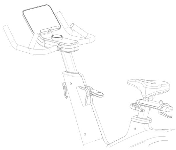
Fig./Img./Abb./Afb./ Rys 12

Fig./Img./Abb./Afb./ Rys 13

Fig./Img./Abb./Afb./Rys 14
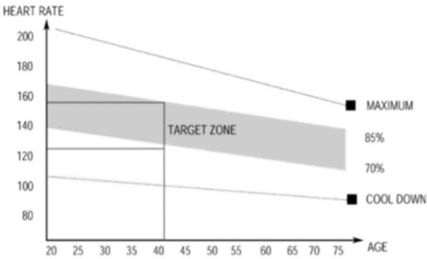
Fig./Img./Abb./Afb./Rys 15
www.cecotec.es

- SOMMAIRE
- INSTRUCTIONS ON BATTERIES
- INSTRUCTIONS DE SÉCURITÉ
- PROCEDIMIENTO
- PARTS AND COMPONENTS
- MOUNTING KIT
- NOTE
- BEFORE USE
- ENGLISH
- BOX CONTENT
- ASSEMBLY
- STEP 1: FRONT AND REAR STABILISER ASSEMBLY
- SETTINGS
- SADDLE HEIGHT ADJUSTMENT (57) / VERTICAL SADDLE POST (14)
- FORE/AFT SADDLE ADJUSTMENT
- FIG. 9
- INSERTION LIMIT
- HANDLEBAR POST HEIGHT
- FIG. 10
- PROCEDURE
- WARNING
- LEVELLING
- FIG. 11
- BRIEF NOTE
- EMERGENCY STOP
- EMERGENCY STOP INSTRUCTIONS
- FIG. 12
- TRANSPORT
- OPERATION
- FUNCTION BUTTONS
- AUTOMATIC PROGRAMMES (P1-P12)
- ALGORITHM
- SLEEP AND AUTOMATIC SHUT-OFF
- HEART RATE CABLE
- EXERCISE GUIDELINES
- WI-FI CONNECTIVITY AND MOBILE APP
- CLEANING AND MAINTENANCE
- TROUBLESHOOTING
- TECHNICAL SPECIFICATIONS
- RECYCLING OF ELECTRICAL AND ELECTRONIC EQUIPMENT
- TECHNICAL SUPPORT AND WARRANTY
- INFORMATION ON DATA STORED BY CONNECTED PRODUCTS IN ACCORDANCE WITH REGULATION (EU) 2023/2854 (“DATA REGULATION”)
- COPYRIGHT
- SIMPLIFIED EU DECLARATION OF CONFORMITY
- PIÈCES ET COMPOSANTS
- PARTI E COMPONENTI
- CONNETTIVITÀ WI-FI E APP
- PEÇAS E COMPONENTES
- ONDERDELEN EN COMPONENTEN
- CZĘŚCI I KOMPONENTY
- SOUČÁSTI A KOMPONENTY
- PROSEDÜR
- PECES I COMPONENTS
Brand : CECOTEC
Model : Drumfit Indoor Pulseride
Category : Fitness Equipment