USER MANUAL MOTORLIFT 2000 CHAMBERLAIN
Manager, Reg. Affairs
COMMENCEZ PAR LIRE CES IMPORTANTES CONSIGNES DE SECURITE

ACCESSIONS: Page 8 - Figure
CHARACTERISTIQUES: Page 8
LISTE DES PIECES POUR LE MONTAGE
ET L'INSTALLATION DU RAIL: Figure [27]
LIST DES PIECES DE
L'OUVRE-PORTE: Figure 28
TYPES DE PORTES - 1
Manager, Reg. Affairs
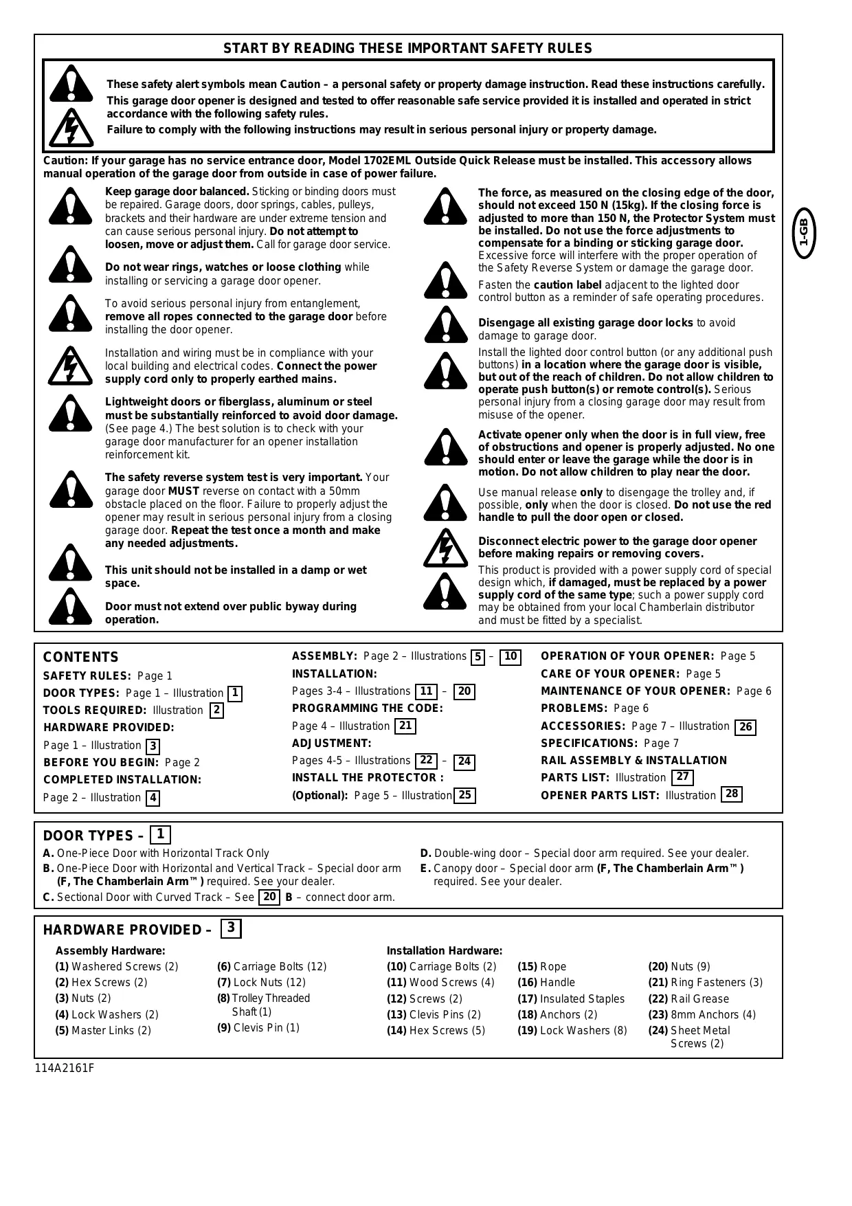
START BY READING THESE IMPORTANT SAFETY RULES


These safety alert symbols mean Caution – a personal safety or property damage instruction. Read these instructions carefully. This garage door opener is designed and tested to offer reasonable safe service provided it is installed and operated in strict accordance with the following safety rules.
Failure to comply with the following instructions may result in serious personal injury or property damage.
Caution: If your garage has no service entrance door, Model 1702EML Outside Quick Release must be installed. This accessory allows manual operation of the garage door from outside in case of power failure.

Keep garage door balanced. Sticking or binding doors must be repaired. Garage doors, door springs, cables, pulleys, brackets and their hardware are under extreme tension and can cause serious personal injury. Do not attempt to loosen, move or adjust them. Call for garage door service.

Do not wear rings, watches or loose clothing while installing or servicing a garage door opener.

To avoid serious personal injury from entanglement, remove all ropes connected to the garage door before installing the door opener.

Installation and wiring must be in compliance with your local building and electrical codes. Connect the power supply cord only to properly earthed mains.

Lightweight doors or fiberglass, aluminum or steel must be substantially reinforced to avoid door damage. (See page 4.) The best solution is to check with your garage door manufacturer for an opener installation reinforcement kit.

The safety reverse system test is very important. Your garage door MUST reverse on contact with a 50mm obstacle placed on the floor. Failure to properly adjust the opener may result in serious personal injury from a closing garage door. Repeat the test once a month and make any needed adjustments.

This unit should not be installed in a damp or wet space.

Door must not extend over public byway during operation.

The force, as measured on the closing edge of the door, should not exceed 150 N (15kg). If the closing force is adjusted to more than 150 N, the Protector System must be installed. Do not use the force adjustments to compensate for a binding or sticking garage door. Excessive force will interfere with the proper operation of the Safety Reverse System or damage the garage door.

Fasten the caution label adjacent to the lighted door control button as a reminder of safe operating procedures.

Disengage all existing garage door locks to avoid damage to garage door.
Install the lighted door control button (or any additional push buttons) in a location where the garage door is visible, but out of the reach of children. Do not allow children to operate push button(s) or remote control(s). Serious personal injury from a closing garage door may result from misuse of the opener.

Activate opener only when the door is in full view, free of obstructions and opener is properly adjusted. No one should enter or leave the garage while the door is in motion. Do not allow children to play near the door.
Use manual release only to disengage the trolley and, if possible, only when the door is closed. Do not use the red handle to pull the door open or closed.

Disconnect electric power to the garage door opener before making repairs or removing covers.
This product is provided with a power supply cord of special design which, if damaged, must be replaced by a power supply cord of the same type; such a power supply cord may be obtained from your local Chamberlain distributor and must be fitted by a specialist.
CONTENTS
SAFETY RULES: Page 1
DOOR TYPES: Page 1 - Illustration
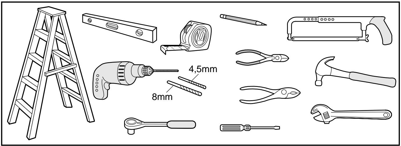
TOOLS REQUIRED: Illustration 2
HARDWARE PROVIDED:
Page 1-Illustration 3
BEFORE YOU BEGIN: Page 2
COMPLETED INSTALLATION:
Page 2 - Illustration 4
ASSEMBLY: Page 2 - Illustrations [5] - [10]
INSTALLATION:
Pages 3-4 - Illustrations 11 - 20
PROGRAMMING THE CODE:
Page 4 - Illustration [21]
ADJUSTMENT:
Pages 4-5 - Illustrations 22 - 24
INSTALL THE PROTECTOR :
(Optional): Page 5 - Illustration [25]
ACCESSORIES: Page 7 - Illustration 26
SPECIFICATIONS: Page 7
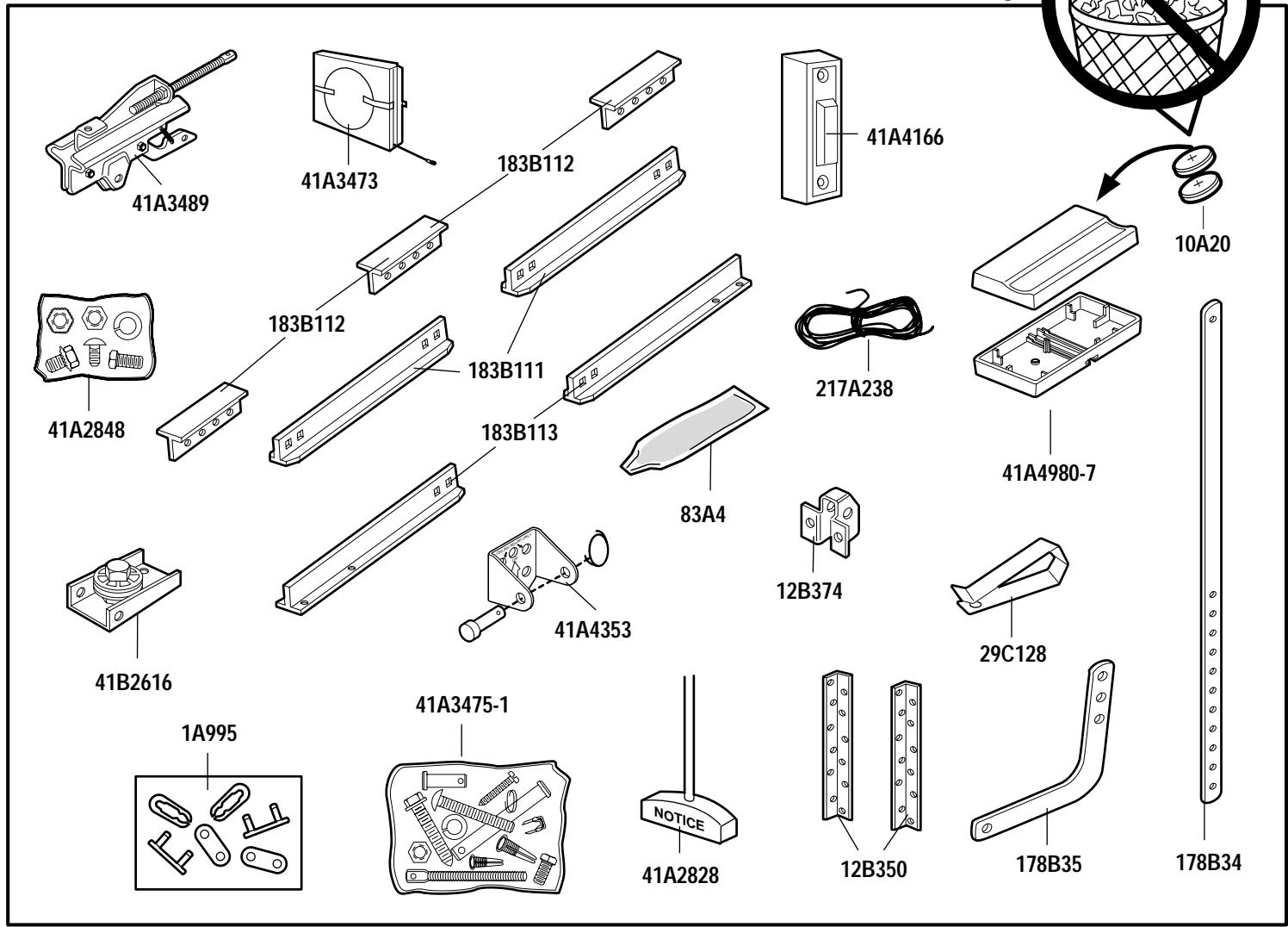
RAIL ASSEMBLY & INSTALLATION
PARTS LIST: Illustration 27
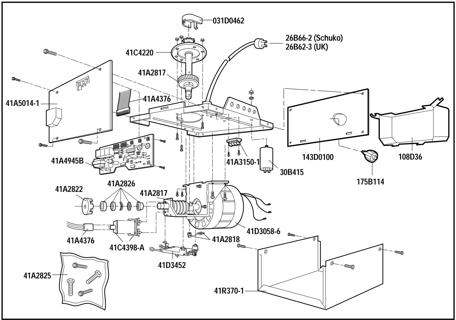
OPENER PARTS LIST: Illustration 28
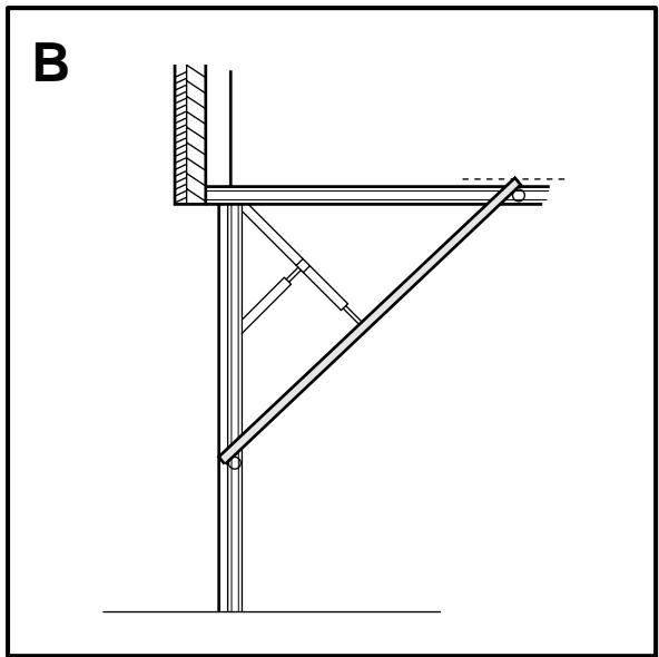
DOOR TYPES - 1
A. One-Piece Door with Horizontal Track Only
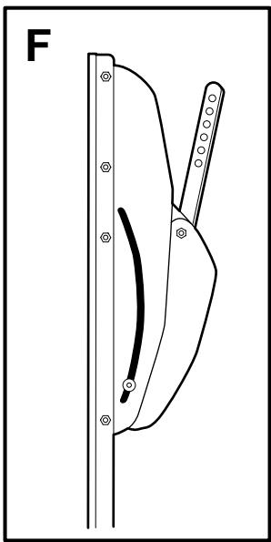
B. One-Piece Door with Horizontal and Vertical Track - Special door arm (F, The Chamberlain Arm™) required. See your dealer.
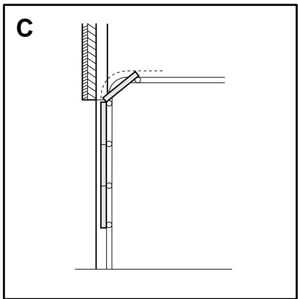
C. Sectional Door with Curved Track - See 20 B - connect door arm.
D. Double-wing door - Special door arm required. See your dealer.
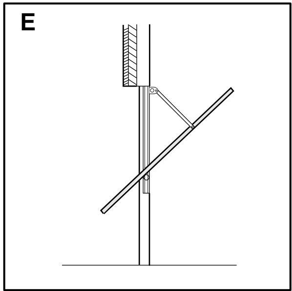
E. Canopy door - Special door arm (F, The Chamberlain Arm™) required. See your dealer.
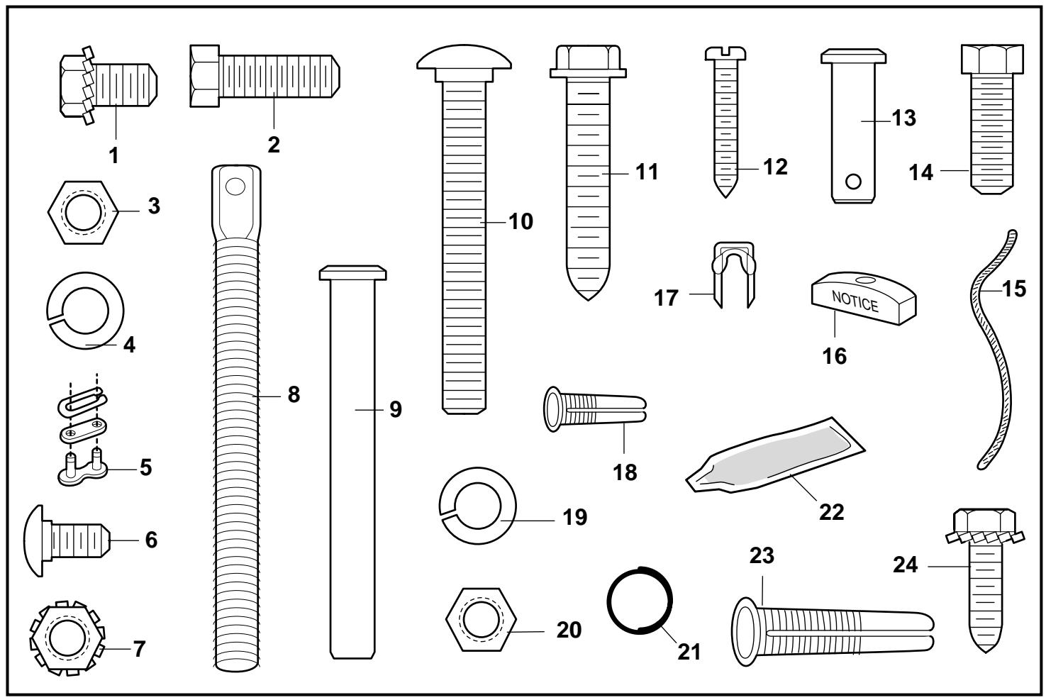
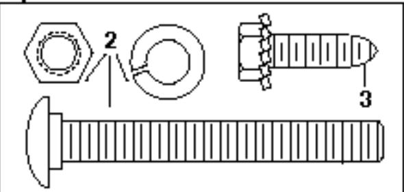
HARDWARE PROVIDED - 3
Assembly Hardware:
(1) Washered Screws (2)
(6) Carriage Bolts (12)
(2) Hex Screws (2)
(7) Lock Nuts (12)
(3) Nuts (2)
(8) Trolley Threaded Shaft (1)
(4) Lock Washers (2)
(9) Clevis Pin (1)
Installation Hardware:
(10) Carriage Bolts (2)
(11) Wood Screws (4)
(12) Screws (2)
(13) Clevis Pins (2)
(14) Hex Screws (5)
(15) Rope
(16) Handle
(17) Insulated Staples
(18)Anchors (2)
(19) Lock Washers (8)
(20) Nuts (9)
(21) Ring Fasteners (3)
(22) Rail Grease
(23) 8mm Anchors (4)
(24) Sheet Metal Screws (2)

BEFORE YOU BEGIN:
- Look at the wall or ceiling above the garage door. The header bracket must be securely fastened to structural supports.
- Do you have a finished ceiling in your garage? If so, a support bracket and additional fastening hardware (not supplied) may be required.
- Depending on your door's construction, you might need a special door arm. See your dealer.
- Do you have an access door in addition to the garage door? If not, Model 1702EML Outside Quick Release Accessory is required.
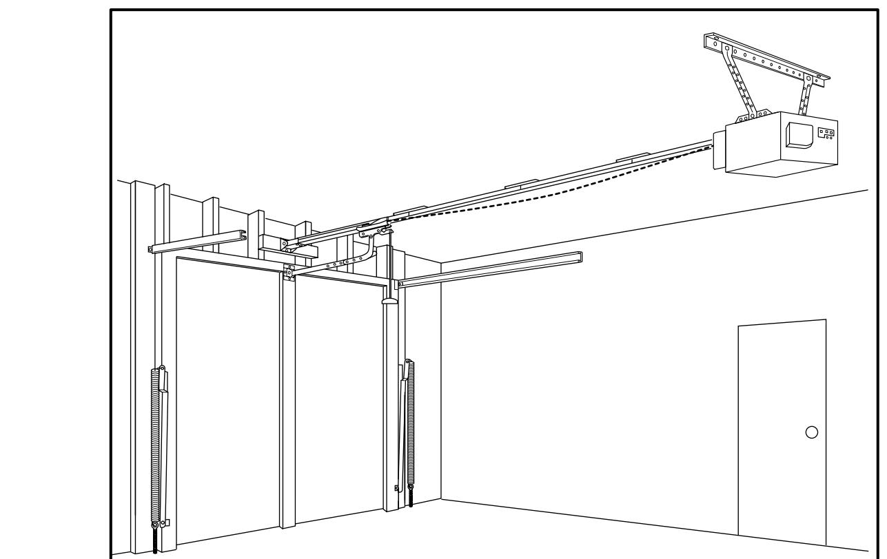
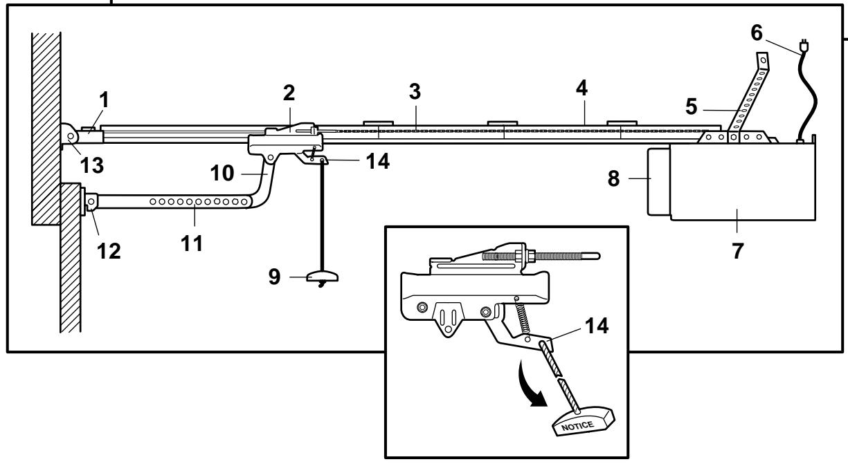
COMPLETED INSTALLATION - 4
As you proceed with the assembly, installation and adjustment procedures in this manual, you may find it helpful to refer back to this illustration of a completed installation.
(1) Cable Pulley Bracket
(9) Manual Release Rope & Handle
(2) Trolley
(10) Curved Door Arm
(3) Chain & Cable
(11) Straight Door Arm
(4) T-rail
(12) Door Bracket
(5) Hanging Bracket
(13)Header Bracket
(6) Power Cord
(14) Trolley Release Arm
(7) Opener
(8) Light lens
ASSEMBLY SECTION 5 - 10
Important: If you have a canopy or dual-track door, you need to use the instructions packed with The Chamberlain Arm™ Accessory in conjunction with this Owner's Manual when assembling the T-rail.
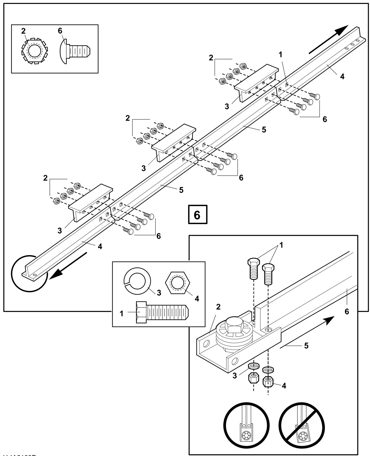
ASSEMBLE THE T-RAIL - 5
Place rail pieces on flat surface for assembly. The center sections with tapered ends (5) are interchangeable. So are the end sections (4). Connect the braces (3) and lock nuts (2) from one side of the rails and insert the carriage bolts (6) from the opposite side. Then the trolley will not hit the lock nuts when it is installed.
The square necks on the carriage bolts must be seated in square holes in rail sections (1).
For canopy and dual-track doors, continue with the instructions in this manual until Step 12.
Position cable pulley bracket (2) on the front section of T-rail (6).
Fasten securely with: screws (1); lock washers (3) and nuts (4).
When tightening the screws, be sure to keep bracket parallel to rail (5). Otherwise, rail may bow when opener is operated.
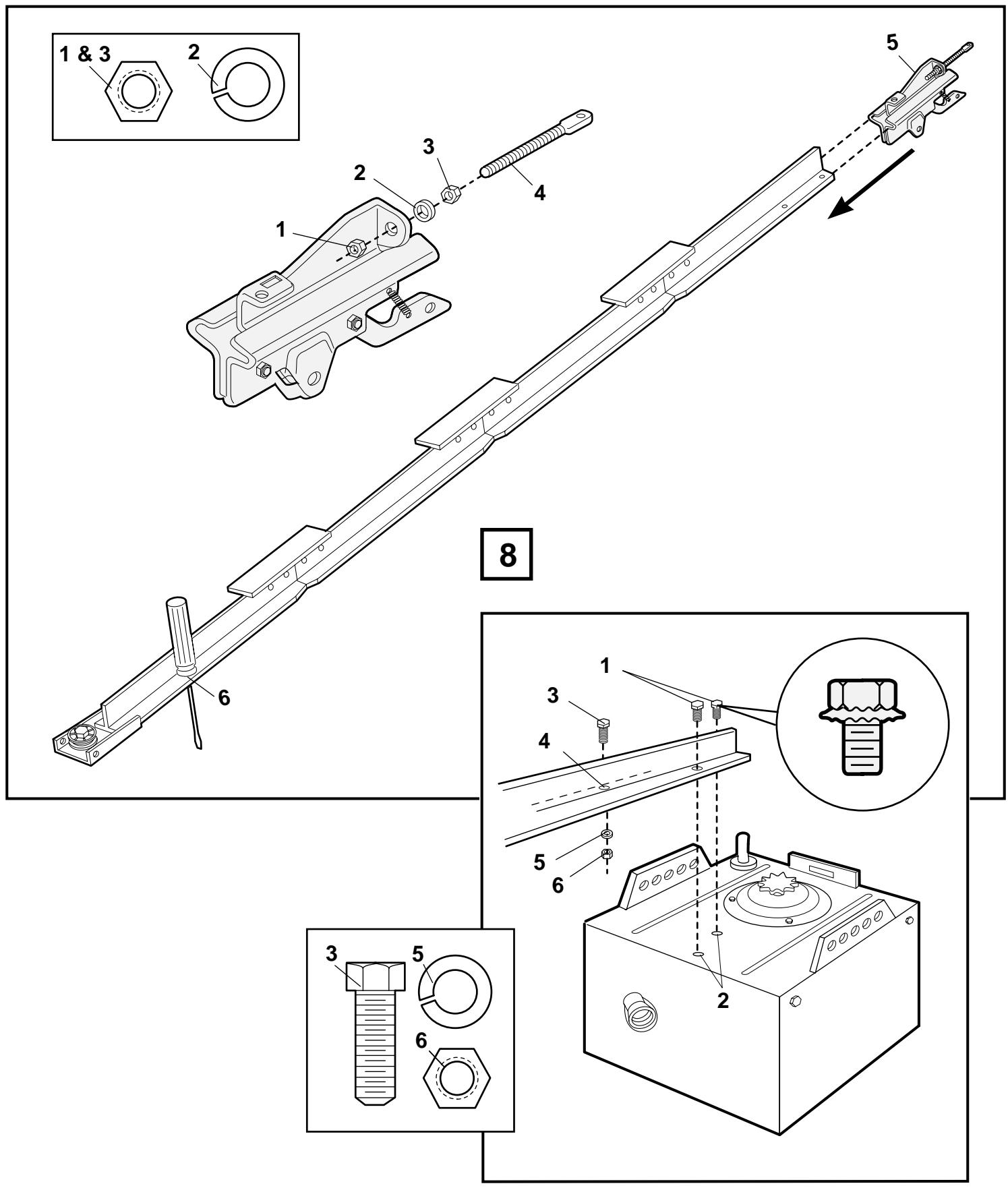
Insert a screwdriver into trolley "stop" hole in the front end of T-rail (6). Attach trolley threaded shaft (4) to the trolley with: lock washer (2), and nuts (1 & 3). Slide trolley (5) along rail to the "stop".
Note: If the trolley hits any nuts on T-rail, review rail assembly and reposition hardware.
FASTEN T-RAIL TO THE OPENER - 8
Place packing material under the opener to protect the opener cover. For convenience, place a support under the cable pulley bracket end of rail.
Remove the (2) washered screws (1) from the top of the opener. Align holes in back end of the T-rail with holes in opener (2).
Fasten the rail to the opener with the same washed screws and tighten securely. Caution: Use only those screws! Use of any other screws will cause serious damage to the door opener.
Insert a hex screw (3) into trolley stop hole in T-rail (4). Tighten securely with a lock washer (5) and nut (6).
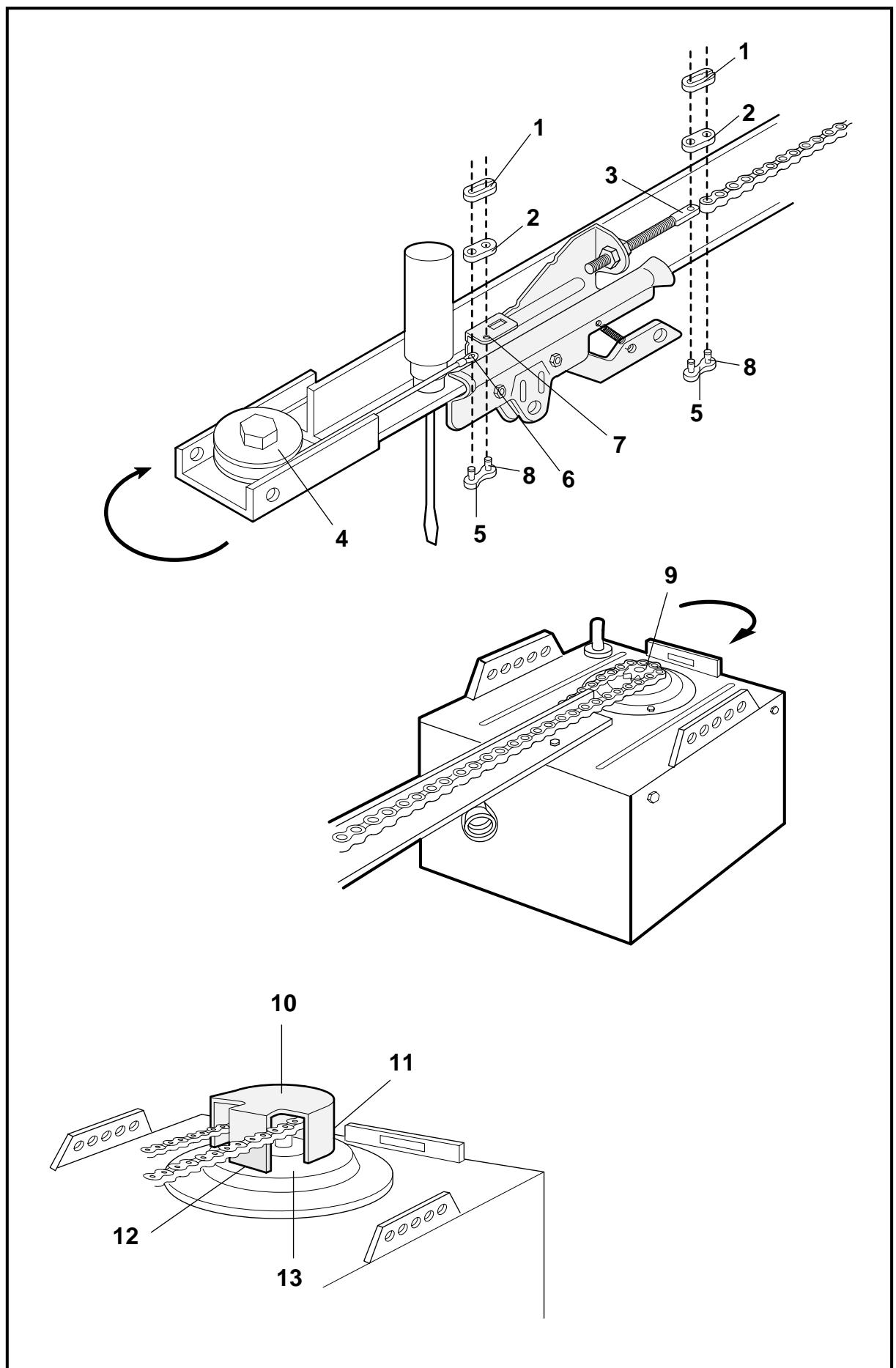
INSTALL THE CHAIN/CABLE & ATTACH THE SPROCKET COVER - 9
Do not remove chain/cable from carton.
Dispense a few inches of cable from carton and fasten to trolley with a master link.
Master Link Procedure: Push pins of master link bar (5) through cable loop (6) and hole in front end of trolley (7). Push cap (2) over pins (8) and onto notches. Slide clip-on spring (1) over cap and onto pin notches until both pins are securely locked in place.
Caution: Keep chain taut during installation to help prevent kinking.
With the trolley against screwdriver, dispense chain/cable around pulley (4). Proceed back around the opener sprocket (9). The opener sprocket teeth must engage the chain. Continue forward to the trolley threaded shaft.
Use the second master link to connect the chain to the flat end of the threaded shaft (3).
Check to make sure the chain is not twisted.
Remove the screwdriver.
To attach the sprocket cover (10), insert the front tab (12) in the opener slot. Using needle nose pliers, push together the two halves of the back tab (11) inserting them on the mounting plate (13). Use reverse procedure to remove.
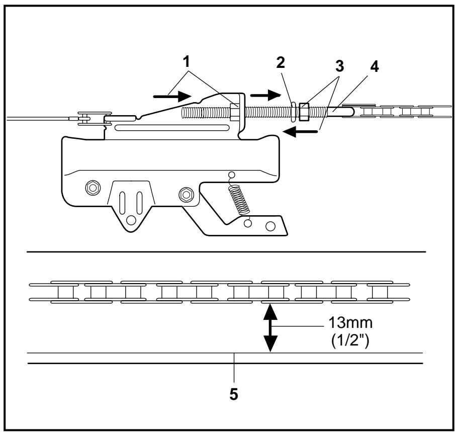
TIGHTEN THE CHAIN/CABLE - 10
Spin inner nut (3) and lock washer (2) down threaded shaft (4).
Check to make sure chain is not twisted.
To tighten the chain, turn outer nut (1) in the direction shown. As you turn the nut, keep the chain from twisting.
When chain is approximately 13mm (1 / 2^ ) above the base of the T-rail (5) at midpoint, re-tighten inner nut.
Sprocket noise can result if chain is either too loose or too tight. When installation is complete, you may notice some chain droop with the door closed. This is normal. If the chain returns to the position described above when the door is open, do not re-adjust the chain.
During future maintenance, ALWAYS pull the manual release handle to disconnect trolley before adjusting chain.
ASSEMBLY OF YOUR OPENER IS NOW COMPLETE.
Wear protective goggles when working overhead to protect your eyes from injury.
Disengage all existing garage door locks to avoid damage to the garage door.
To avoid serious personal injury from entanglement, remove all ropes connected to the garage door before installing the opener.
Installation of this product shall comply with ZH1/494, VDE 0700 Part 238, and VDE 0700 Part 1.
It is recommended that the opener be installed 2,1m (7 feet) or more above the floor where space permits.
The header bracket must be rigidly fastened to a structural support of the garage. Reinforce the wall or ceiling with a 40mm (1-1/2") board if necessary. Failure to comply may result in improper operation of safety reverse system.
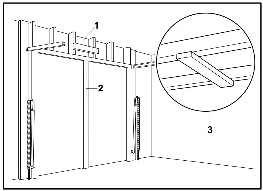
You can attach the header bracket either to the header wall (1) or to the ceiling (3). Follow the instructions which will work best for your particular requirements.
With the door closed, mark the vertical centerline (2) of the garage door. Extend line onto header wall above the door.
Open door to highest point of travel. Draw an intersecting horizontal line on header wall 5cm (2") above high point to provide travel clearance for top edge of door.
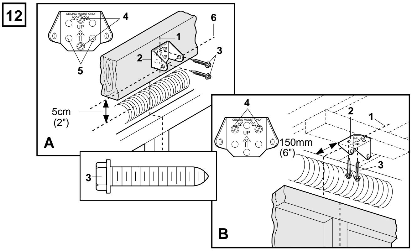
A. Wall Mount: Center the bracket (2) on the vertical guideline (1) with the bottom edge of the bracket on the horizontal line (6) (with the arrow pointing toward the ceiling).
Mark either set of bracket holes (4 or 5). Do not use the holes designated for ceiling mount. Drill 4,5mm (3 / 16^ ) pilot holes and fasten the bracket with wood screws (3).
B. Ceiling Mount: Extend vertical guideline (1) onto the ceiling.
Center the bracket (2) on the vertical mark no more than 150mm ( 6'' ) from the wall. Make sure the arrow is pointing toward the wall.
Mark holes designated for ceiling mount only (4). Drill 4,5mm (3/16") pilot holes and fasten the bracket with wood screws (3).
Position opener on garage floor below the header bracket. Use packing material to protect the cover.
Note: To enable the T-rail to clear sectional door springs, it may be necessary to lift opener onto a temporary support.
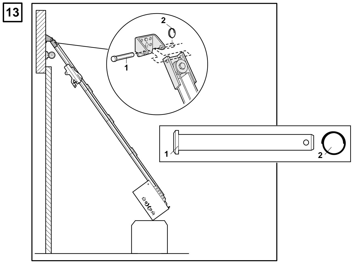
The opener must either be secured to a support or held firmly in place by another person.
Raise T-rail until cable pulley and header brackets come together. Join with clevis pin (1). Insert ring fastener (2) to secure.
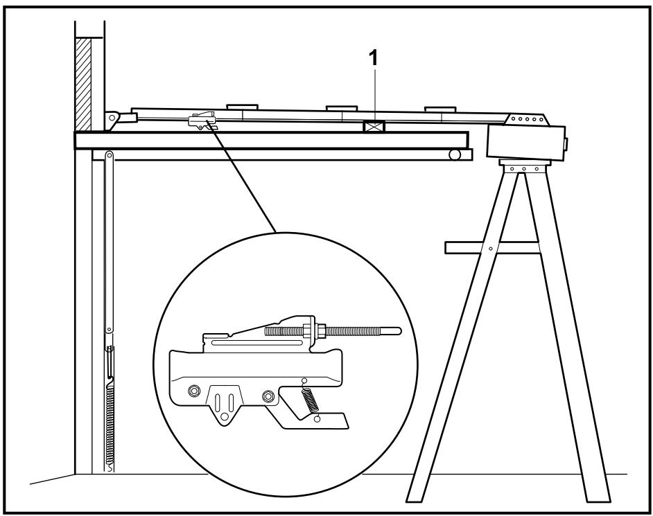
POSITION THE OPENER - 14
Note: A 25mm (1") board (1) is convenient for setting an ideal door-to-T-rail distance (unless headroom is not sufficient).
Raise the opener onto a stepladder. Open garage door. Place a 25mm (1") board (1) laid flat on the top section of door near the centerline as shown. Rest the T-rail on the board.
If the raised door hits the trolley, pull down on the trolley release arm to disconnect the inner and outer trolley sections. The trolley can remain disconnected until connecting door arm to trolley is completed.
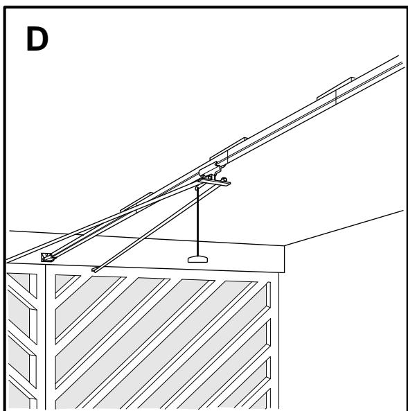
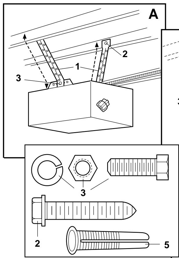
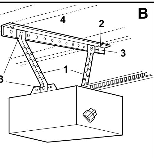
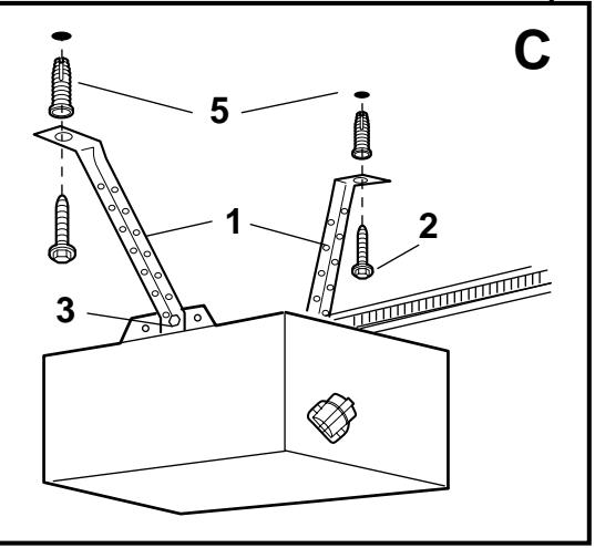
HANG THE OPENER - 15
The opener must be securely fastened to a structural support of the garage.
Three representative installations are shown. Yours may be different. Hanging brackets (1) should be angled (Figure A) to provide rigid support. On finished ceilings, (Figure B) attach a sturdy metal bracket (not supplied) (4) to a structural support before installing the opener. For concrete ceiling mount, (Figure C), use concrete anchors (5) provided.
On each side of opener measure the distance from the opener to the structural support (or ceiling).
Cut both pieces of the hanging bracket to required lengths. Flatten one end of each bracket and bend or twist to fit the fastening angles. Do not bend at the bracket holes. Drill 4,5mm (3/16") pilot holes in the structural supports (or ceiling). Attach flattened ends of brackets to supports with wood screws (2).
Lift opener and fasten to hanging brackets with screw, lock washer and nut (3). Check to make sure T-rail is centered over the door.
REMOVE 25mm (1") board. Operate door manually. If door hits the rail, raise header bracket.
Grease the top and underside of rail surface on which the trolley slides. A tube of grease is supplied.
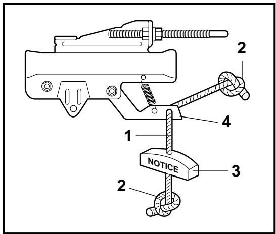
ATTACH MANUAL RELEASE ROPE & HANDLE - 16
Thread one end of rope (1) through hole in top of red handle so "NOTICE" reads right side up as shown (3). Secure with an overhand knot (2). Knot should be at least 25mm (1") from end of the rope to prevent slipping.
Thread other end of rope through hole in release arm of the outer trolley (4). Adjust rope length so that handle is 1,8m (6 feet) above the floor. Secure with an overhand knot.
Note: If it is necessary to cut rope, heat seal cut end with a match or lighter to prevent fraying.
CONNECT ELECTRIC POWER
TO AVOID INSTALLATION DIFFICULTIES, DO NOT RUN THE GARAGE DOOR OPENER UNTIL INSTRUCTED TO DO SO.
Connect the opener to a mains which is properly EARTHED according to the wiring instruction tag attached to power supply cord (and as specified by local code).
Connect the door opener only to an outlet controlled by a double pole switch.
Locate push buttons where the garage door is visible, away from door and door hardware and out of the reach of children.
Serious personal injury from a moving garage door may result from misuse of opener. Do not allow children to operate the lighted door control button or remote control transmitter.
Fasten the caution label on the wall near the lighted door control button as a reminder of safe operating procedures.
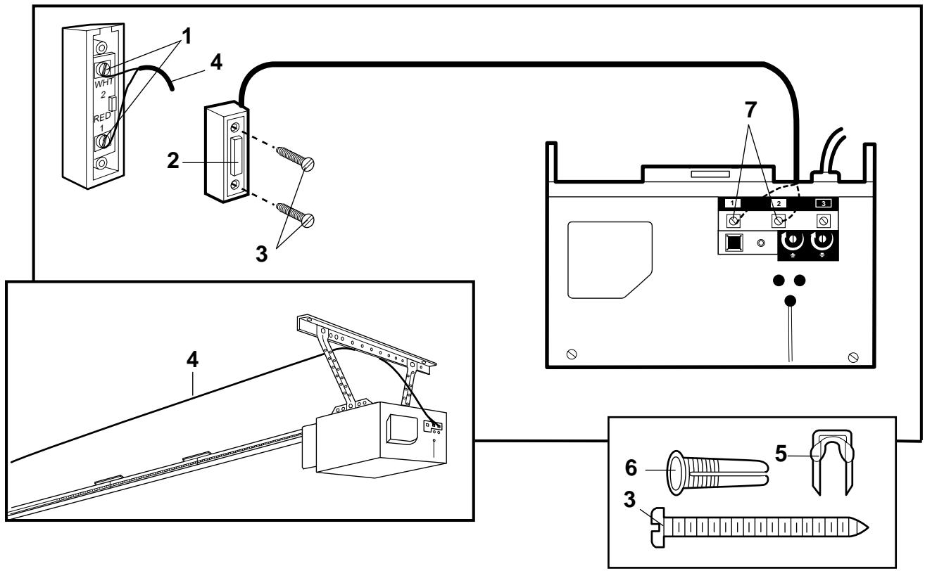
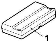
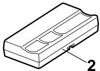
There are 2 screw terminals (1) on the back of the lighted door control button (2). Strip about 6mm (1/4") of insulation from bell wire (4).
Separate wires enough to connect the white/red wire to terminal screw 1 and the white wire to terminal screw 2.
Fasten the lighted door control button to an inside garage wall with sheet metal screws (3) provided. Drill 4mm (5 / 32^ ) holes and use anchors (6) if installing into drywall. A convenient place is beside the service door and out of reach of children.
Run the bell wire up the wall and across the ceiling to the garage door opener. Use insulated staples (5) to secure wire. The receiver terminal screws (7) are located on the back panel of the opener. Connect the bell wire to the terminal screws as follows: white/red to 1 and white to 2.
Press to open or close the door. Press again to reverse the door during the closing cycle or to stop the door during opening cycle.
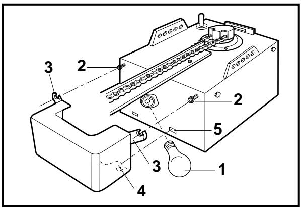
INSTALL THE LIGHT AND LENS - 18
Install a 40 watt maximum light bulb (1) in the socket as shown. The light will turn on and remain lit for 4-1/2 minutes when power is connected. After 4-1/2 minutes it will turn off.
Replace burned out bulbs with rough service light bulbs.
Loosen the two screws (2) near top of opener front panel. Position lens against panel with slotted tab (3) behind screws. Snap bottom tabs (4) of lens into panel slots (5). Tighten top panel screws to secure lens.
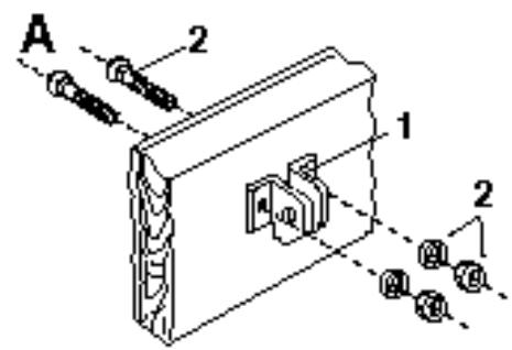
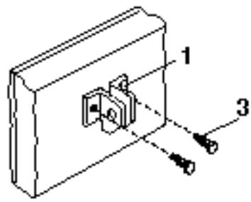
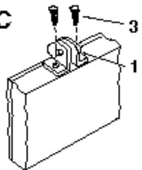
FASTEN DOOR BRACKET - 19
If yours is a canopy or dual-track style garage door, a door arm conversion kit is required. Follow the installation instructions included with the replacement door arm.
Exercise care in removing and assembling arm conversion kit. Keep fingers away from the sliding parts.
Sectional and One-Piece Door Installation Procedure:
-
Center bracket (1) at the top of inside face of door as shown. Mark holes.
-
A. Wooden doors
Drill 8mm (5/16") holes and fasten the door bracket with nut, lock washer, and carriage bolt (2).
B. Sheet metal doors
Fasten with sheet metal screws (3).
C. One-piece door optional
Fasten with sheet metal screws (3).
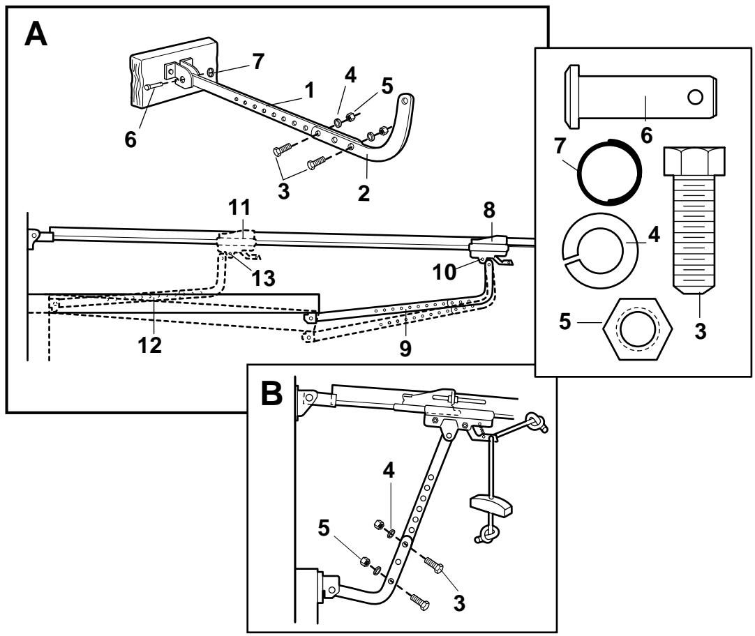
CONNECT DOOR ARM TO TROLLEY - 20
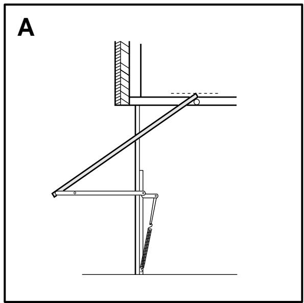
Sectional Door Installation: Note door arm configuration in Figure B. One-Piece Door Installation: Procedure (Figure A).
Connect straight door arm (1) and curved door arm sections (2) to obtain the longest possible length with hardware (3, 4 & 5). With door closed, connect straight door arm section to door bracket with a clevis pin (6). Secure with a ring fastener (7).
Before connecting door arm to trolley, adjust travel limits. Limit adjustment screws are located on left side panel.
Open Door Adjustment: Decrease up limit. Turn up limit adjustment screw counterclockwise 5-1/2 turns.
Press door control button. Trolley will travel to full open position (8). Manually raise door to open position (parallel to floor) and lift door arm (9) to trolley. The arm should touch trolley just in back of door arm connector hole (10) as shown in solid line drawing. Increase up limit if necessary. One full turn equals 5cm (2") of door travel.
Closed Door Adjustment: Decrease down limit. Turn down limit adjustment screw clockwise 5 complete turns.
Press door control button. Trolley will travel to full closed position (11). Manually close door and lift door arm (12) to trolley. The arm should touch trolley just ahead of door arm connector hole (13) as shown in dotted line drawing. Decrease down limit if necessary. One full turn equals 5cm (2") of door travel.
Connect Door Arm to Trolley: With door closed, connect curved arm to trolley with remaining clevis pin. Secure with ring fastener. Note: Lift door slightly to make connection if necessary.
Run opener through a complete travel cycle. If door has a slight "backward" slant in full open position, decrease up limits until door is parallel to floor.
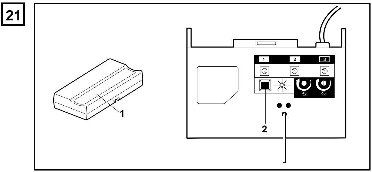
PROGRAM YOUR OPENER & REMOTE - 21
Activate the opener only when door is in full view, free of obstruction and properly adjusted. No one should enter or leave garage while door is in motion. Do not allow children to operate push button(s) or remote(s). Do not allow children to play near the door.
Your garage door opener receiver and remote control transmitter are set to a matching code. If you purchase additional remote controls, the garage door opener must be programmed to accept the new remote code.
Program the Receiver to Match Additional Remote Control Codes
-
Press and hold the remote control push button (1).
-
Press and release the "Smart" button (2) on the back panel of the opener. The opener light will flash once.
-
Release the remote push button.
Now the opener will operate when the remote control push button is pressed.
If you release the remote control push button before the opener light flashes, the opener will not accept the code.
To Erase all Remote Control Codes
- Press and hold the "Smart" button on the opener panel until the indicator light turns off (about 6 seconds). All the codes the opener has learned will be erased.
- To reprogram, repeat Steps 1 - 3 for each remote control in use.
ADJUSTMENT SECTION 22 - 24
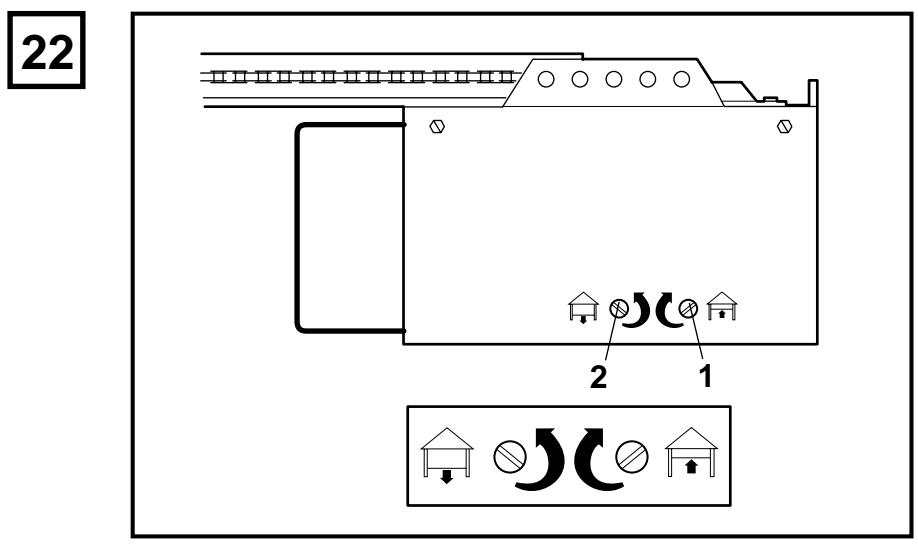
LIMITADJUSTMENT-22
Run the opener through a complete travel cycle. Limit adjustments are not necessary when the door opens and closes completely and doesn't reverse unintentionally in the fully closed position.
Situations requiring limit adjustment are listed below. Run the opener through a complete travel cycle after each adjustment.
Note: Repeated operation of the opener during adjustment procedures may cause motor to overheat and shut off. Allow a 15 minute cooling period after 5 continuous operations of the opener. Read the following carefully before proceeding to Force Adjustment. Use a screwdriver to make limit adjustments.
If Door Doesn't Open Completely but Opens at Least 1,5m (5 feet): Increase up travel. Turn the up limit adjustment screw (1) clockwise. One turn equals 5cm ( 2'' ) of travel.
If door does not open at least 1,5m (5 feet): Adjust up (open) force. See Force Adjustment.
If Door Doesn't Open Completely: If door arm is at maximum length, increase down travel. Turn down limit adjustment screw (2) counterclockwise. One turn equals 5cm (2") of travel. If the door still will not close completely, the header bracket is positioned too high.
If Opener Reverses in Fully Closed Position: Decrease down travel. Turn down limit adjustment screw (2) clockwise. One turn equals 5cm (2") of travel.
If Door Reverses when Closing and there is no Interference to Travel Cycle: Test door for binding. Pull manual release handle. Manually open and close door. If door is binding, call a door serviceman. If door is not binding or unbalanced, adjust down (close) force.
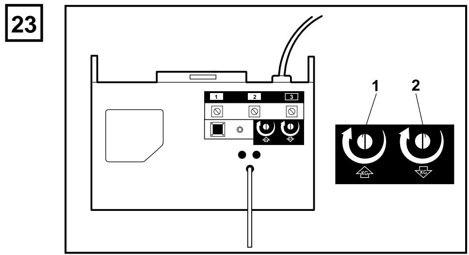
FORCE ADJUSTMENT - 23
The force, as measured on the closing edge of the door, should not exceed 150N (15kg). If the closing force is adjusted to more than 150N , the Protector System must be installed.
Do not use force adjustments to compensate for a binding or sticking garage door. Excessive force will interfere with proper operation of safety reverse system or damage garage door.
Force Adjustment Controls (1 & 2) are located on the back panel of opener.
If the force adjustments are set too light, door travel may be interrupted by nuisance reversals in down direction and stops in up direction. Weather conditions can affect the door movement, occasional adjustment may be needed.
Maximum force adjustment range is 260 degrees, about 3/4 of a complete turn. Do not force controls beyond that point. Turn force adjustment controls with a screwdriver.
Test Down (Close) Force: Grasp the door handle or door bottom when door is about halfway through down (close) travel. Door should reverse. (Reversal halfway through down travel does not guarantee reversal on a 50mm obstruction.) If the door is hard to hold or doesn't reverse, decrease down (close) force by turning the control (2) in a counterclockwise direction. Make small adjustments until door reverses normally. After each adjustment, run opener through a complete cycle.
If Door Doesn't Open at Least 1,5m (5 feet): Increase up (open) force by turning the control (1) in a clockwise direction. Make small adjustments until door opens completely. Re-adjust up limit if necessary. After each adjustment, run opener through a complete travel cycle.
If Door Reverses During Down (Close) Cycle: Increase down (close) force by turning the control (2) in a clockwise direction. Make small adjustments until door completes close cycle. After each adjustment, run the opener through a complete travel cycle.
Do not increase the force beyond the minimum amount required to close the door.
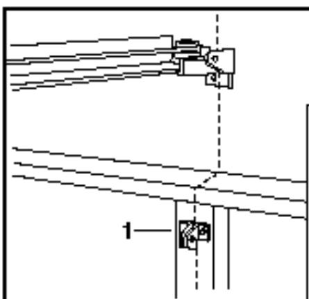
TEST THE SAFETY REVERSE SYSTEM - 24
The safety reverse system test is important. Garage door must reverse on contact with a 50mm obstacle laid flat on the floor. Failure to properly adjust opener may result in serious personal injury from a closing garage door. Repeat test once a month and adjust as needed.
Procedure: Place a 50mm obstacle (1) laid flat on the floor under the garage door. Operate the door in the down direction. The door must reverse on the obstruction. If the door stops on the obstruction, it is not traveling far enough in the down direction. Increase the down limit by turning down limit adjustment screw counterclockwise 1/4 turn.
Repeat test.
When the door reverses on the 50mm obstacle, remove the obstruction and run the opener through a complete travel cycle. Door must not reverse in closed position. If it does, adjust Limits and Force and repeat safety reverse test.
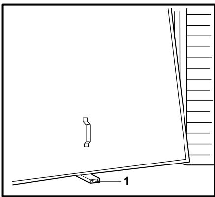
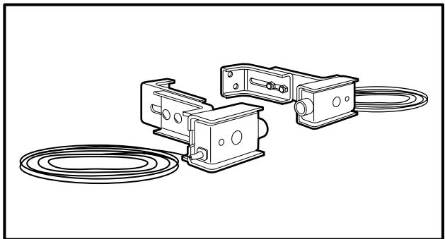
INSTALL THE PROTECTOR (OPTIONAL) - 25 (See accessories)
The force, as measured on the closing edge of the door, should not exceed 150N (15kg). If the closing force is adjusted to more than 150N , the Protector System™ must be installed.
After opener has been installed and adjusted, The Protector System™ accessory can be installed. Instructions are included with this accessory.
The Protector System™ provides an additional measure of safety against a small child being caught under a garage door.
It uses an invisible beam which, when broken by an obstruction, causes a closing door to open and prevents an open door from closing and is strongly recommended for homeowners with young children.
Your opener can be activated by any of the following devices:
- The Lighted Door Control Button. Hold the button down until door starts to move.
- The Outside Keylock or Keyless Entry System (if you have installed either of these accessories).
- The Remote Control Transmitter. Hold the push button down until the door starts to move.
Opening the Door Manually:
Door should be fully closed if possible. Weak or broken springs could allow an open door to fall rapidly. Property damage or serious personal injury could result.
The door can be opened manually by pulling the release handle down and back (toward the opener). To reconnect the door, pull the release handle straight down. It will reconnect on the next UP or DOWN operation.
Do not use the manual release handle to pull the door open or closed.
When the Opener is Activated by Remote Control:
- If open, the door will close. If closed, the door will open.
- If closing, the door will reverse.
- If opening, the door will stop (allowing space for entry and exit of pets and for fresh air).
- If the door has been stopped in a partially open position, it will close.
- If an obstruction is encountered while closing, the door will reverse.
- If an obstruction is encountered while opening, the door will stop.
- The optional Protector System™ uses an invisible beam which, when broken by an obstruction, causes a closing door to open and prevents an open door from closing. It is STRONGLY
RECOMMENDED for homeowners with young children.
Allow a 15 minute cooling period after 5 continuous operations of the opener.
The opener light will turn on: 1. when opener is initially plugged in;
2. when the power is interrupted; 3. when the opener is activated.
The light turns off automatically after 4-1/2 minutes. Bulb size is 40 Watts maximum.
CARE OF YOUR OPENER
When properly installed, opener will provide high performance with a minimum of maintenance. The opener does not require additional lubrication.
Limit and Force Adjustments: These adjustments must be checked and properly set when opener is installed. Only a screwdriver is required. Weather conditions may cause some minor changes in the door operation, requiring some re-adjustments, particularly during the first year of operation.
Refer to the limit and force adjustments on pages 4 & 5. Follow the instructions carefully and repeat the safety reverse test after any adjustment.
Remote Control Transmitter: The portable remote control may be secured to a car sun visor with the clip provided. Additional remotes can be purchased at any time for use in all vehicles using garage. Refer to Accessories. The receiver must be programmed to operate with any new remote.
Remote Control Battery: The lithium batteries should produce power for up to 5 years. When the light becomes dim or does not come on, replace the battery. If transmission range lessens, check the battery test light.
To Change Battery: To replace batteries, use the visor clip or screwdriver blade to pry open the case. Insert batteries positive side up. To replace cover, snap shut along both sides. Do not dispose of the old battery with household waste. Take batteries to a proper disposal center.
MAINTENANCE OF YOUR OPENER
Once a Month:
- Repeat safety reverse test. Make any necessary adjustments.
- Manually operate door. If it is unbalanced or binding, call for professional garage door service.
- Check to be sure door opens and closes fully. Adjust Limits and/or Force if necessary.
Twice a Year:
- Check chain tension. Disconnect trolley first. Adjust if necessary.
Once a Year:
Oil door rollers, bearings and hinges. The opener does not require additional lubrication. Do not grease the door tracks.
HAVING A PROBLEM?
1. Opener doesn't operate from remote control:
- Does the opener have electric power? Plug lamp into outlet. If it doesn't light, check the fuse box or the circuit breaker. (Some outlets are controlled by a wall switch.)
- Have you disengaged all door locks? Review installation instruction warnings on page 1.
- Is there a build-up of ice or snow under the door? The door may be frozen to ground. Remove any obstruction.
- The garage door spring may be broken. Have it replaced.
- Repeated operation may have tripped the overload protector in the motor. Wait 15 minutes. Try again.
2. Remote has short range:
- Is battery installed? Check battery test light. If the light is dim, change the battery.
- Change the location of the remote control on the car.
- A metal garage door, foil-backed insulation or metal siding will reduce the transmission range.
3. Door reverses for no apparent reason and opener light doesn't blink:
- Is something obstructing the door? Pull manual release handle. Operate door manually. If it is unbalanced or binding, call for professional garage door service.
- Clear any ice or snow from garage floor area where garage door closes.
- Review Force Adjustment.
- If door reverses in FULLY CLOSED position, decrease travel limits.
Repeat safety reverse test after adjustment is complete.
The need for occasional adjustment of the force and limit settings is normal. Weather conditions in particular can affect door travel.
4. Door reverses for no apparent reason and opener light blinks for 5 seconds after reversing:
Check The Protector System™ (if you have installed this accessory). If the light is blinking, correct alignment.
5. Opener noise is disturbing in living quarters of home:
If operational noise is a problem because of proximity of the opener to the living quarters, Vibration Isolator Kit 41A3263 can be installed. This kit was designed to eliminate the "sounding board effect" and is easy to install.
6. The garage door opens and closes by itself:
- Is there a neighbor with a garage door opener using the same frequency code? Change your code.
- Make sure remote push button is not stuck "on".
7. Door stops but doesn't close completely:
Review Travel Limits Adjustment.
Repeat safety reverse test after any adjustment of door arm length, close force or down limit.
8. Door opens but won't close:
- Check The Protector System™ (if you have installed this accessory). If the light is blinking, correct alignment.
- If opener light does not blink and it is a new installation, check the down force.
Repeat the safety reverse test after the adjustment is complete.
9. Opener light does not turn ON:
Replace light bulb (40 Watts maximum). Replace burned out light bulbs with rough service light bulbs.
10. Opener light does not turn OFF:
There may be a defective earth at the ceiling or wall receptacle. The unit must be earthed.
11. Opener strains or maximum force is needed to activate door:
Door may be unbalanced or springs are broken. Close door and use manual release rope and handle to disconnect trolley. Open and close door manually. A properly balanced door will stay in any point of travel while being supported entirely by its springs. If it does not, call for professional garage door service to correct the problem.
Do not increase the force to operate the opener.
12. Opener motor hums briefly, then won't work:
- Garage door springs are broken. SEE ABOVE.
- If problem occurs on first operation of opener, door is locked.
Disable door lock. If chain was removed and reinstalled, the motor may be out of phase. Remove chain; cycle motor to down position. Observe drive sprocket. When it turns in clockwise direction and stops in down position, re-install chain.
Repeat safety reverse test after adjustment is complete.
13. Opener won't activate due to power failure:
- Pull manual release rope and handle down and back to disconnect trolley. Door can be opened and closed manually. When the power is restored, pull the manual release handle straight down. The next time the opener is activated, the trolley will reconnect.
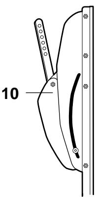
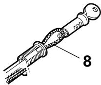
- The Outside Quick Release accessory 1702EML (if fitted) disconnects the trolley from outside the garage in case of power failure.
14. The chain droops or sags:
It is normal for the chain to droop slightly in the closed door position. Use the manual release rope and handle to disconnect the trolley. If the chain returns to the normal height when the trolley is disengaged and the door reverses on a 50mm obstacle laid flat, no adjustments are needed.
ACCESSORIES - 26
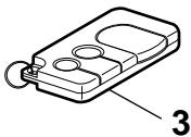
(1) Model 4330EML............Single-Function Remote Control
(2) Model 4333EML. 3-Function Remote Control
(3) Model 4335EML. 3-Function Mini Remote Control
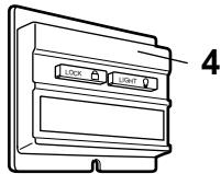
(4) Model 845EML......... Multi-Function Door Control Panel
(5) Model 75EML............Lighted Door Control Button
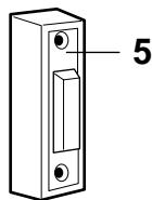
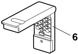
(6) Model 747EML ..... Keyless Entry System
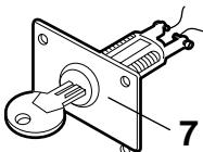
(7) Model 760EML. .Outside Keylock
(8) Model 1702EML. Outside Quick Release
(9) Model 770EML. The Protector SystemTM
(10) Model 1703EML. The Chamberlain ArmTM
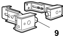
(11) Model 1EML......Door Handle Quick Release
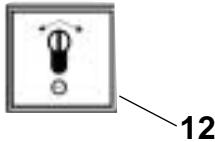
(12) Model 34EML. 2-Position Key Switch Flush Mount
Model 41EML.2-Position Key Switch Surface Mount
WIRING INSTRUCTIONS FOR ACCESSORIES
Keyless Entry System - To opener terminals: Red-1 and White-2
Lighted Push Button - To opener terminals: Red-1 and White-2
Outside Keylock - To opener terminals: Red-1 and White-2
System^TM - To opener terminals: White-2 and Black-3
Door Control Panel - To opener terminals: Red-1 and White-2
REPLACEMENT PARTS 27 - 28
SPECIFICATIONS
Max.Pull Force .600N
Watts 500
Motor
Type .Permanent split capacitor
Speed. 1500 rpm
Volts 230-240 Volts AC-50Hz Only
Drive Mechanism
Gears. 16:1 worm gear reduction
Drive.........Chain/cable with one-piece trolley on steel T-rail.
Length of Travel .......Adjustable to 2,29m (7-1/2 feet)
Travel Rate. 178mm (7 inches) per second
Lamp . . . . . . . . . . . . . . . . . . . . . . . . . . . . . . . . . . . . . . . . . . . . . . . . . . . . . . . . . . . . . . . . . . . . . . . . . . . . . . . . . . . . . . . . . .. on when door starts, off 4-1/2 minutes after stop.
Door Linkage............Adjustable door arm. Pull cord trolley release.
Safety
Personal ...Push button and automatic reversal in down direction. Push button and automatic stop in up direction.
Electronic....Independent up and down force adjustment screws.
Electrical............Motor overload protector and low voltage push button wiring.
Limit Device.....Circuit actuated by limit nut.
Limit Adjustment............Screwdriver adjustment on side panel.
Start Circuit............Low voltage push button circuit.
Dimensions
Length (Overall) 3,11m (122-1/2 feet)
Headroom Required....5cm (2 inches)
Hanging Weight.14,5 kg (32 lb)
Receiver Memory Registers
Computer Code. 12
Code Switch. 1
Keypad. 1
Automatic Garage Door Opener....Model No. 2000ML
is in conformity to the
applicable sections of Standards.. EN 300 220-3, EN55014, EN61000-3,
ETS 300 683, & EN60335-1
per the provisions & all amendments
of the EU Directives 1999/5/EC, 73/23/EEC, 89/336/EEC
Declaration of Incorporation
Automatic Garage Door Opener Model No. 2000ML, when installed and maintained according to all the Manufacturer's instructions in combination with a Garage Door, which has also been installed and maintained according to all the Manufacturer's instructions, meet the provisions of EU Directive 89/392/EEC and all amendments.
I, the undersigned, hereby declare that the equipment
specified above and any accessory listed in the manual
conforms to the above Directives and Standards.
THE CHAMBERLAIN GROUP, INC.
Elmhurst, IL 60126
USA
May, 2003


Barbara P. Kelkhoff
Manager, Reg. Affairs
BEGYND MED AT LAESE DISSE VIGTIGE SIKKERHEDSBESTEMMELSER


Side 1 - illustration [3]
FOR DU BEGYNDER: Side 2
FAERDIG INSTALLATION:
Side 2 - Illustration [4]
SAMLING: Side 2 - illustration 5 - 10
MONTAGE: Side 3-4 - illustration [11] - [20]
PROGRAMMERING AF KODE:
Side 4 - illustration [21]
JUSTERUNG:
Side 5 - illustration [22] - [24]
INSTALLATION AF FOTOCELLE:
(ekstraudstyr): Side 6 - illustration 25
BETJENING AF ABNEREN: Side 6
PLEJE AF ABNEREN: Side 6
VEDLIGEHOLDELSE AF ABNEREN: Side 6
PROBLEMER: Side 7
EKSTRAUDSTYR: Side 8 - Illustration [26]
SPECIFICATIONER: Side 8
LISTE MED DELE TIL SAMLING OG
MONTAGE AF SKINNER: illustration 27
LISTEMEDDELTILABNEREN:
illustration 28
PORTTYPER-1
A. Vicpeport med vandret koreskinne
B. Vippeport med lodret og vandret koreskinne - speciel portarm kræves (F, The Chamberlain Arm™). Henvend dig til forhandleren.
FASTGOR PORTBESLAGET-19
4-1/2 minut after stop.
Manager, Reg. Affairs
Manager, Reg. Affairs
APXISTE IABAZONTA TOY IAPAKAT HMANTIKOY KANONE A A OY XPH H

Ta ouo 1ou 6e n e Tne unoohawovn Poooxh- oynia oxetikn e aopalia n nepiouiaekn othopa. Iaabaote autou tou iouc t cnoyie c npooxh.

O napw unxaviooc ykapa zonoptac exi oxdeltaei kai dokiaotiet wote va npoepeia aopaa nleitoupyia o loyika nlaiaia Tn npounoean otexi tonoetnei kai xpnaimoieital oe auotnp oupwvia touc napakawavoce aopaaeic.
Mn oumuoppwon me tic napakatw odnyiec mnpoei va exei av anotelao oobap npoosniok tpaumaio n nepiouiaik opa.
IPOSOXH: Av to ykapac oac dEv exi bontnki npota npenei va xonaiuonoiothe i EeWtepikoc Mxavioos Taxiaas Aneauepwons, movteLo un apiOov 1702EML. To eapntma auto eipenei tnv ano eew xiepokivtny Ieitoupyia nC ykapazonopraos nepintwn diakonnps peuatoq.

Aiatnpes Tny ykapaonopota 1o0uyioevn. NpTeC
Tou kolavc mepiKa n teleiwc npTei va
eNtiOipOwovtai. KappaOpntec, eLaTpiia, oupatooiva, troxaliec, unootniymuata kai o EOnlIoouc
TOUC Bpiokovta OE katOtaaON EApetiknc PpoEvtaoNCS
Kai mToPOuV v npokaEosouv oobapo tpaumatuo. Mnu
ENIXeIPnoTe va xalapoeTe, va eTakivnoTe n va ta
puBmuTe. Kaote EVAV texviko yia YkapaonopTe Cya service.

Mn φopáte δaxtulidia, poLóyia n xalapó pouxioó
ótav éykaθiσtáte n ouvtnpeite tv ykapαζonopta.

Tia nV anopuyn oObetaou npoosniKou tpaumatou ano nepinlok/npedega, apaipote ola ra oxovia nou evai npooeva otny ykapaoptra npiv Eykataotnoe tov mXavioo avoiyatoC.

H EykataoTaon mKapaZoNpOtaC kai n NkTpiKn EYkataoTaon npEe iva eivai oupwyn e Touc tonikoou OIKoobuikoc kai NkEkoPoioyikouc KwDkec. Suvoe To Kaawio npoxn cpuatoC mov o osotyiwepo puato0t.

Elaqpc ykapacoprec kataokuapevcs ano ualo- 6aoka (fiberglass), aoumuio n xala8 npentvi aevioxouov onuavtikya via anopeuxtheta 8a8n touc. (BlenTe e5iida 5.) H kalutepn luon eivai v ououaueteite Tnv kataokuaotpiia tepia iayu KIT evioxuan c ykataotaon mnxaviou avoiyatoc.

H dokuniou Suotmuoc Aopaleiac Avitropoic civa tonu oynavikn.H ykapaconopta IPENEIva avtotpeei tny ka0do ts e nepittwn enapncs eptodio uous 5mm totoe tmevou sto edaooc. H lavthetav npueiou tu mxaov aoiyuotc mtopei va exia av anoteloeqa oobapo npooaniko tpaatao kata to kaeioo ts ykapaconoptac. EnavaalabaveTt dokuniKahe mva kai kavte TAnapaitntec puoiieic.

H movada autn n npen va ykataaota oε μepos με vepa uypaia.

H npota v npeni va npva naww ano o nepaoka tna litoupyia tnC.

H duvaun, onwuc autn metpatai otny aknp klaiojatoc tnc npotac, dev th npenvi va xenepva ta 150N (15kg).Eav n duvaun klaiajatoac nnc npotac puotiotei etoi wote va xenepva ta 150N, th npentai v ykataoataei to Suotma Ipoataia. Mn xonoiopoite rtc puotiieic duvauewv ia va avtotaouste to npobaauiac ykapaonoptac nou exkiokaiae iepika n teleicw. Ytpboaikn pnoevtaantheta uinodioeim oownt aeitouyia tou zuotniatoC Aopaliaoc Avtiopocn ng n npokaalee iabn ont ykapaoionpta.

Eiouvayte Tny EIKETT npoooxns iinla oTo Teivo diakontn yia va unevthetai tic owotc diaikaaicx xoncs.

Tia nV anopuyn Znmuac Tnc ykapaZonoptac ELeuOepwote 0aes Tc KLEIDapie Cns YkapaZonoptac.
ToioeTne To VwTeivo DIAKOTn (nooiouc npooetouc diakOTTec) oepoc ano onou paiveiaykapaCOnopta aaaa nou va un npopoovva faoovnuiaia. Mny einnpene Tse naia v xaonmuoiouv tov(touc) diakottn(8c) toixou n to(Ta) nAEXEpiotn-pio(a).Kaon xonon Tou mnxavioum avoiymuato c mtopci va npokaloeoi ooapopnpoowniktopaumaiqmo kat to klaioigo tnS ykapaCOnoptac.
Evpyonoiote to mnxaviog aoiyaroc mvo otav n npota qaiivtai olokAnp, ivai eAevopn ano emnoia kai o mnxaviogoc aoiyaroc exi puthetai tei owot. Aev npenei kaveic va maivei n va byaivei ano to ykapac 00n npota bpioketai oe kivnon. Mny emtpenente OE naidi va naizoukov kovt a ony ykapaczopota.
XpnooioioteTov unxavioxepokivtns aneueuepownc movo ia va anoboeaeuoet To opeio kal av eiva epiKTó, mvo eoosov n npota evai kLeiotm. Mny xpnoiponoieTe Tov KOKivo bpaixova (tpaewvTac tov) ia TO avoiyma n KLeioIO TnS npotac.
Anouvdeoteovnchiaviogavoiyuatoykaapocnpa ano to pEu npiv ano emokuee n aphaipoeon kalmuatw.
To npoiov auto auvobutai ano kaawio napoxn Cpmuatoc iokns oxdelta nou,av api, npem va avtikataotbi ano idiou toun kawio. Mnpit va npounthetai avtaalaktiko kaawio ano tov tokiok oac avtinpoo wto ts Chamberlain. H ykataotaon tou kaawio npenvi yiv ano idko.

NEPIEXOMENA
KANONEAΦAΛEIAΣελiδa1
SYNTHPHESH TOY MHXANEMOY
ANOIRMATO2: i a7
NPOBAHMATA: i 7-8
Barbara P. Kelkhoff Manager, Reg. Affairs
delle Normative EU 1999/5/EC, 73/23/EEC, 89/336/EEC
Manager, Reg. Affairs
LES DISSE VIKTIGE SIKKERHETSREGLENE FØR DU BEGYNNER


VEDLIKEHOLD AV APNEREN: Side 6
PROBLEMER: Side 7
Deler for montering:
(1) Skruermed
underlagsskive
(2) Sekskantskruer (2)
(3) Muttere (2)
(4) Laseskiver (2)
(5) Kjedelåser (2)
Deler for installations:
(10) Festebolter (2)
(11) Treskrueer (4)
(12) Skruer (2)
(13) Gaffelbolter (2)
(14) Sekskantskruer (5)
(15) Snor
(16) Händtak
(17) Isolerte stifter
(18) Murplugger (2)
(19) Laseskiver (8)
(20) Muttere (9)
(21) Ringfester (3)
(22) Tube med
smoremiddel
(23) 8mm Murplugger (4)
(24)Blikskruer (2)
FØR DU BEGYNNER:
- Undersøk veggen eller taket over garasjeporten. Veggfestet mæ være sikkert festet til garasjens bærestruktur.
- Er garasjetaket ditt fertigbehandlet? I sa fall kan dukommen til a trenge en stottebrakett og ekstra festedeler (ikke vedlagt).
- Det kan vare at du trenger en spezialarm, avhengig av hvilken type port du har. Kontakt forhandleren.
- Har du en sidedør i tillegg til garasjeporten? Hvis ikker, er utvendig nødutløser modell 1702EML, påkrevd.
FULLFORT INSTALLASJON - 4
VEDLIKEHOLD AV APNEREN
Vedlikehold en gang i帽子en:
Gjenta testen av sikkerhetsreverseringen. Foreta nødvendige justeringer.
- Betjen porten manuelt. Hvis den er i ubalanse eller er treg, bør du kontakte et serviceverksted.
- Kontroller at porten Åpner og lukker seg fullstendig. Juster grensene og/eller kraften hvis det er nødvendig.
To ganger i Året:
Registre for mottakerminne
Datakode 12
Kodebryter. 1
Knappepanel.1
Automatisk garasjeportapner . Model 2000ML
samsvarer med
Manager, Reg. Affairs
LEES EERST DEZE BELANGRIJKE VEILIGHEIDSVOORSCHRIFTEN


Repeat the safety reverse test after the adjustment is complete.
Manager, Reg. Affairs
COMECE POR LER ESTAS IMPORTANTES REGRAS DE SEGURANÇA


Manager, Reg. Affairs
BÖRJA MED ATT LÄSA IGENOM DESSA VIKTIGA SÄKERHETSFÖRESKRIFTER


Denna varningssignal pakllar forsiktiget - anvisning betraffande personlig sakerhet erer egendomskada. Läs dessa anvisiningar noggrant.
Manager, Reg. Affairs
ALOITA LUKEMALLA NÄMÄ TÄRKEÄT SUOJAOHJEET


Manager, Reg. Affairs

D Abbildungen - Garagentoröffner Modell MotorLift 2000
Figures - Modèle MotorLift 2000 de ouvre-porte de garage
GB Illustrations - Garage Door Operator Model MotorLift 2000
DK Illustration - Model MotorLift 2000 Garageportsaabner
E Ilustraciones - Abridor de la puerta de garage, Modelo MotorLift 2000
GR Σχήμα - Mηχανισμός Avoίγματος Γκαραζόπορτας, Movτέλo MotorLift 2000
I Illustrazioni - Apriorta per garage Modelo MotorLift 2000
N Illustrasjon - Garasjeportapner, Modell MotorLift 2000
NL Afbeeldingen - Model MotorLift 2000 Garagedeuropeaner
Figuras - Operador automatico de porta, Modelo MotorLift 2000
s Bild. - Garageportöppnare Modell MotorLift 2000
SF Kuvat - Autotallin ovenavaaja, Malli MotorLift 2000

114A2162E
2
3
4
5

11
14
15
16
17
18
19
B
C
20
24
25
26
4330EML
4333EML
4335EML
845EML
75EML
1703EML
747EML
760EML
1702EML
770EML
1EML
34EML/41EML