WK SERIE - Garage door opener CHAMBERLAIN - Free user manual and instructions
Find the device manual for free WK SERIE CHAMBERLAIN in PDF.
User questions about WK SERIE CHAMBERLAIN
0 question about this device. Answer the ones you know or ask your own.
Ask a new question about this device
Download the instructions for your Garage door opener in PDF format for free! Find your manual WK SERIE - CHAMBERLAIN and take your electronic device back in hand. On this page are published all the documents necessary for the use of your device. WK SERIE by CHAMBERLAIN.
USER MANUAL WK SERIE CHAMBERLAIN
Jumper Position AUF/Open/OUVERT
Selbsthaltung
Self Locking
Automaintien
Jumper Position ZU/CLOSE/FERME
Totmann
Hold to run
Homme-mort

ZU
CLOSE
FERME


7 6 5 4


CHAMBERLAIN
GAROG
HUBKRAFT MIT PRAZISION
Torsteuerung AS 210
geprüft nach:
WKN070, WKK070, WKS070
IMPORTANT SAFETY ADVICE 3-4
GENERAL INFORMATION 4
PREPARATORY TASKS 5
INSTALLATION ADVICE
MOUNTING ARRANGEMENT 6
INSTALLATION ADVICE
ELECTRICAL CONNECTION 7
LIMIT SWITCH ADJUSTMENT 8-10
Technical Drawings 25-27
CE Declaration of Conformity 28
IMPORTANT SAFETY INFORMATION
Before installation, operation or maintenance of this door drive, this operating manual must be read through carefully and all the safety advice must be followed.

This symbol means "Caution" and stands in front of safety advice intended to avoid personal injury or material damage. Please read such advice carefully. The door drive is of course designed and tested for safe operation. It is however only possible to guarantee this if the following safety instructions are accurately followed during installation and operation.

This symbol is intended to advise that if the respective instruction is not followed serious personal injury or material damage can occur.

The door should be counterbalanced. If this is not done then additional measures must be taken, such as unwinding protection, to guarantee proper operation. In the case of DKA drives unwinding protection is standard! Non-movable or stuck doors must be repaired. Doors, door springs, cables, pulleys, retainers and rails are under extreme tension in such situations and this can lead to serious injuries.

Do not attempt to loosen, move or realign the door yourself. Contact your maintenance service.

Suitable protective clothing should be worn during maintenance or installation of the door opener. This includes safety glasses, back supporting belt, and protective gloves. When installing or maintaining a door opener no jewellery, watches or loose clothing may be worn. When working from ladders or on extended platforms the corresponding safety procedures must be followed.

To avoid serious injuries resulting from getting tangled or caught in the mechanisms, all ropes and chains, which are connected to the door, must be removed before installing the door opener.

During installation and connection of the electrical supply the local building and electrical regulations must be followed. Power cables may only be connected to a properly earthed network.
This system must not be installed in damp or wet rooms.

Work on the door opener may only be carried out by one (1) person working on his own.

When working on the door opener all the local safety regulations must be observed. Installation of this device must be done according to EN12453.

The force on the closing door edge must not exceed 150N(15kg) . If the closing force is set to more than 150N then the corresponding additional safety accessories must be installed (see "Installation of safety applications"). The force must never be set to move a stuck door.

Too high a force leads to faults in the proper operation of the reversing system or to damage to the door.

To remind all operators of the safety procedures the corresponding warning sign should be attached beside the operating control unit.

To avoid damage to the door all the blocking devices should be deactivated. If however the blocking devices must remain in operation an unlatching switch can be installed.

The three-switch block, main disconnecting switch and all other control devices must be installed within view of the door and out of reach of children. Children should not be allowed to operate switches or the remote controller. Misuse of the door opener can lead to serious injuries.

The door opener may only be operated if the operator can see the whole door area, if it is free from obstacles and the door opener is properly adjusted. No one may pass through the door while it is moving and children must not be allowed to play in the vicinity of the door.

Before carrying out repairs or removing the covers on the door opener, it is essential to ensure that no one can inadvertently start the drive by installing a lockout device or disconnecting the cables.
Live and moving parts of electrical machines can cause serious or fatal injuries. The installation, connection and starting up, as well as maintenance and repair work may only be carried out by qualified specialist personnel.

To avoid damage to the door or the drive, all the locking devices must be put out of operation. Set locking device(s) to the "Open" position. If a lock is to remain in operation an unlatching switch must be installed.
Please find the technical data for the geared motor from the type plate or from the attached documents.
In doing so you should also follow:
The instructions in this manual
All other project planning documents for the drive
The start-up instructions and circuit diagrams
The currently-valid national regulations (safety and accident prevention)
Guarantee, storage
It is essential to follow these instructions and advice since they are the basis for trouble-free operation as well as for any guarantee claims. Check the delivery immediately after receipt for any transport damage. Report any damage immediately to the transport company as well as to the supplier. If you do not install the geared motor straight away you should store it in a dry, dust-free, low-vibration room at temperatures between 0 and +40^ .
Delivered condition
Every geared motor is manufactured according to the valid technical documentation and subjected to a test run at Chamberlain. We retain the right to make changes to technical data and design, which are in the interests of progress. Dispatch takes place in the appropriate packaging.
GENERAL INFORMATION
We thank you for purchasing our product
still have questions on the installation then please contact:

ChamberlainGmbH,Alfred-Nobel-Str.4
66793 Saarwellingen Germany
Tel: (0049)(0)6838-907222
Fax: (0049)(0)6838-907179
e-mail: info@garog-service.de
internet: www.garog-service.de
The drive may only be installed:

If the details on the rating plate on the drive correspond with the mains voltage.
If the drive is undamaged
If the ambient temperature is between -20^ and +60^
If the installation height is not more than 1000m above sea level
If the type of protection has been appropriately selected.
Output shafts and mounting surfaces are to be thoroughly cleaned to remove the corrosion protection agent (use standard commercial solvent). To avoid material damage the solvent must not get onto the sealing edges of the rotary shaft seals. Abrasive agents must not be used.
To avoid shaft breakages and hence serious or fatal injuries it is essential to note the following during mounting:
The precondition for suitable dimensioning of the shaft with respect to its fatigue strength is stress-free installation and an immovable bearing device for the gearbox support as well as any additional or essential supporting bearings in each direction as supplied by the user.
The machine frame and force introduction points are to be designed with respect to construction and strength according to the bearing forces which arise. The gearbox housing with two bearings and all the other bearing points are located on a common, stable framework on which the bearing surfaces have been machined in one operation. Thereby the installer must ensure that any deformation of the frame under load will not have any negative influences on the shaft load. The screws may only be fully tightened once the gearbox has been accurately aligned. Installation in damp rooms or in the open air is only permitted following agreement with the manufacturer. If the drives are stored for a lengthy period of time it is also necessary to discuss this with the manufacturer.
INSTALLATION ADVICE
Before starting the installation work make sure that all the necessary safety measures have been implemented.
1. Installation
Place machine down on smooth mounting plate or aligned slide rails and tighten fixing screws uniformly.
Make sure beforehand that:
The drive is not damaged or sticking
The drive has been reprepared after a lengthy storage period
The supply line is switched off and safeguarded against being switched on again (VDE regs.) (VDE = German assoc. of electronic engineers)
The connections have been made properly
The turning direction of the geared motor is correct
All motor protection devices are active
No other danger sources exist
Mounting arrangement 1
WKK
Mounting arrangement 2
Closing direction
WKK
WKN

INSTALLATION ADVICE
Electrical connection
The connections according to the circuit diagram and the maintenance of the electrical drive may only be carried out by electrical specialist personnel.

The corresponding accident prevention regulations must be followed.
For switching the motor and the brake connections, switching contacts of utilization category AC-3 acc. to IEC 158 must be used.

The types of line and their cross-sections must be selected according to the relevant regulations. The nominal flows and the type of connection are given on the motor type plate. The drive details must agree with the connected values.

If operated with electronic control devices it is essential to take account of the corresponding start-up instructions and circuit diagrams.
Commissioning:
During commissioning check whether:
The drive does not get excessively hot
In the event of unusual running noises the drive must be stopped immediately and Customer Services should be informed. If oil is lost Customer Services should be called, the oil level should be checked by means of the dipstick on the vent screw and the drive must also be switched off if the level falls below the minimum filling quantity.
To ensure efficient support in the event of a fault we require the following information:
The data from the type plate on your drive unit
The type and extent of the fault
- When and under what accompanying conditions the fault occurred.
- Whether the drive was subject to speed variations or other distinctive happenings
ELECTRICAL CONNECTION

Before the installation of power cables and control devices it is essential to take note of all the following specifications and warnings. If they are not heeded serious injuries or damage to the drive can occur.

The control housing of the door drive may only be opened by trained"Chamberlain" specialist personnel. If necessary please contact your local Chamberlain dealer.

Before electrical installation or the starting up of the drive please study the circuit diagram carefully. The valid local regulations must be followed for all the electrical wiring work.

Before carrying out any maintenance work on the door drive it is first necessary to disconnect the power supply / power transmission at the main switch.

After completion of the maintenance work the danger zone must be cleared and secured again before restarting.
If you require additional accessories or spare parts please contact your local Chamberlain dealer.
CHAMBERLAIN - GmbH
Alfred-Nobel-Str. 4
66793 Saarwellingen
ORDERING FAX NO: (0049)(0)6838-907179
TECHNICAL HOTLINE: (0049)(0)6838-907222
MATRIX FOR THE USE OF SAFETY EQUIPMENT
| TYPE OF CONTROL | DOOR WILL BE USED BY | ||
| Trained people(inaccessible to the public) Group 1 | Public area Group 2 | (General public area) Group 3 | |
| Control by continuous switch operation | A | B | No info. |
| Pulse actuation within visual range of door | C | C and D | C and E |
| Automatic control | C and D | C and E | C and E |
I A: Pushbutton for control by holding down continuously
I B: Keyswitch, or suchlike for controlling by means of continuous actuation
C: Limitation of driving force by force limiting (clutch) and protection devices
(safety edge padding).
I D: Device to detect people or obstacles which are on the ground on one side (inside) of the door
leaf (infrared light barrier)
E: Device to detect people or obstacles which are on the ground on both sides
(inside and outside) of the door leaf (infrared light barrier).
ADVICE: For more detailed information see EN12453.
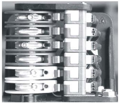
Operator equipped with AS2-eco come with the limit switch LSS-4. (Limits for OPEN & CLOSE and SAFETY-Limit-Switch Open and Closed, without additional limits)
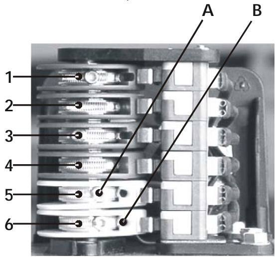
- Additional Limit Switch OPEN green
- Limit Switch OPEN green
- Safety Limit Switch OPEN red
- Safety Limit Switch CLOSED red
- Limit Switch CLOSED white
-
Additional Limit Switch CLOSED white
-
Drive the door to wished CLOSED position.
- Set the control cam 5 (white) the way that the limit switch is operated.
- Tighten the fixing screw A.
- Drive the door to wished OPEN position.
- Set the control cam 2 (green) the way that the limit switch is operated.
- Tighten the fixing screw A.
- Fine adjustment is done with the screw B.
- The safety limit switches 3 and 4 (red) must be set the way that they react directly after passing the control limit switch.
- After the operation test, control the fixing screw.
- The additional limit switches 1 and 6 have change-over contact free of potential.
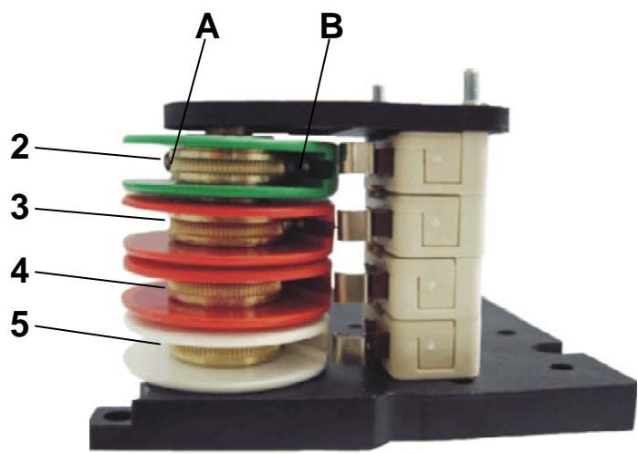
- Limit Switch OPEN green
- Safety Limit Switch OPEN red
- Safety Limit Switch CLOSED red
-
Limit Switch CLOSED green
-
Drive the door to wished CLOSED position.
- Set the control cam 5 (white) the way that the limit switch is operated.
- Tighten the fixing screw A.
- Drive the door to wished OPEN position.
- Set the control cam 2 (green) the way that the limit switch is operated.
- Tighten the fixing screw A.
- Fine adjustment is done with the screw B.
- The safety limit switches 3 and 4 (red) must be set the way that they react directly after passing the control limit switch.
- After the operation test, control the fixing screw.
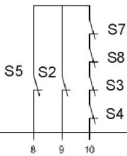
SCHEMATIC DIAGRAM
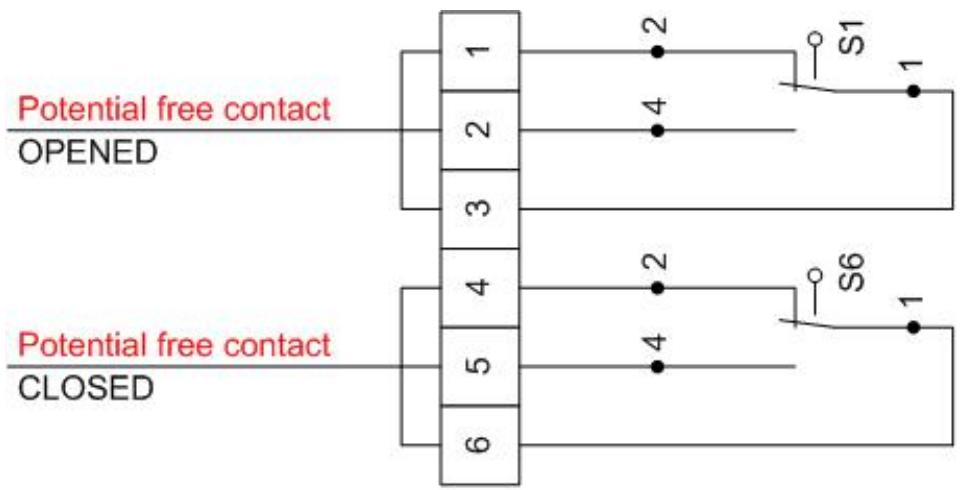
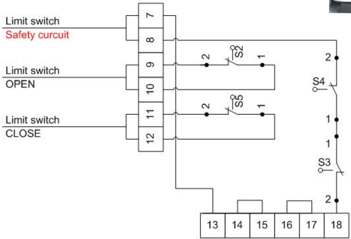
Internal safety curcuit
S1 = Optional Limit switch OPEN (Standard only with limit switch LSS-6)
S2 = Limit Switch OPEN
S3 = Safety limit OPEN
S4 = Safety limit CLOSE
S5 = Limit switch CLOSE
S6 = Optional limit switch CLOSE (Standard only with limit switch LSS-6)
AS2-eco
Tested according to: EN 12453

The door control AS2-eco is conceived to operate door units with single-phase motors in dead-man operation mode.
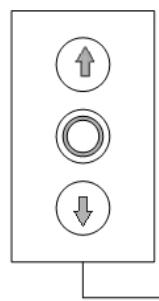
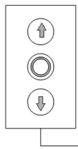
For example, a triple switch is connected with to open or close a gate.
SAFETY INSTRUCTIONS
- Please consider valid national and local directives and regulations related to the start-up of motorised doors in your country. The person and/or the company installing the unit is responsible of the complete unit. The installer has to respect the important norms and directives ( such as DIN EN 12453, DIN EN 13241-1) and establish the technical documents related to the whole unit. The technical documents have to be enclosed to the door's unit.
- Installation and maintenance works at the control AS2-eco have only to be done by specialised technicians in electrics.
- During works on electrical devices, the unit must be switched off supply. All regulations related to protection must be considered.
Dead-man operation mode is only allowed if the unit is visible from the instruction switches and the operators were instructed correspondingly.
The operation of the gate control in self-locking mode is only allowed if the protecting equipment required in EN 13241-1 und EN 12453 are used.

If you do not respect the safety instructions, you are personally liable for the resulting damages on persons and materials.
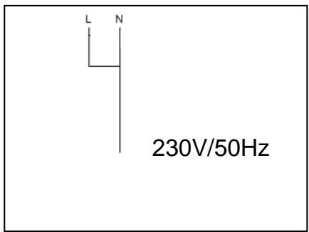
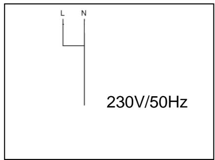
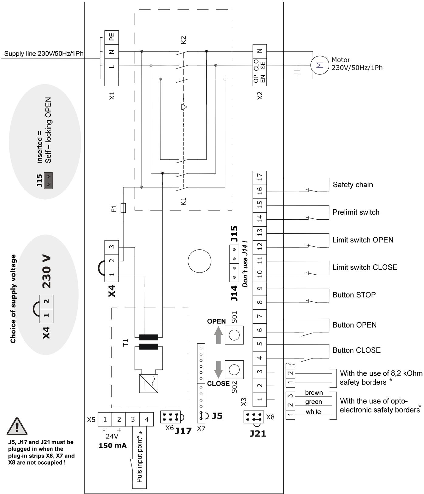
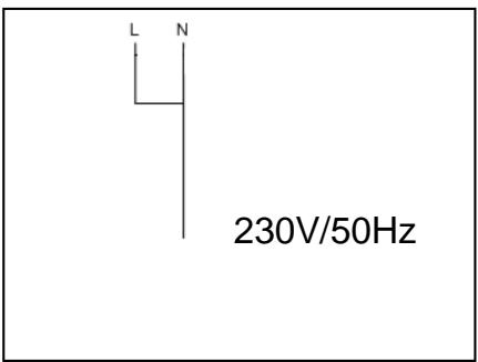
Connection of mains cable
The circuit distribution protected by fuse has to be connected to the screw terminals X1, L, N of the motherboard. The value of safety fuse should not exceed 4A.
The mains plug must be accessible and installed near by the control.
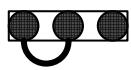
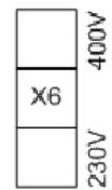
The value of the supply voltage (230V AC or 400V AC) must be set at the screw terminal X6 through the bridge.

A wrong connection of the bridge may destroy the control.
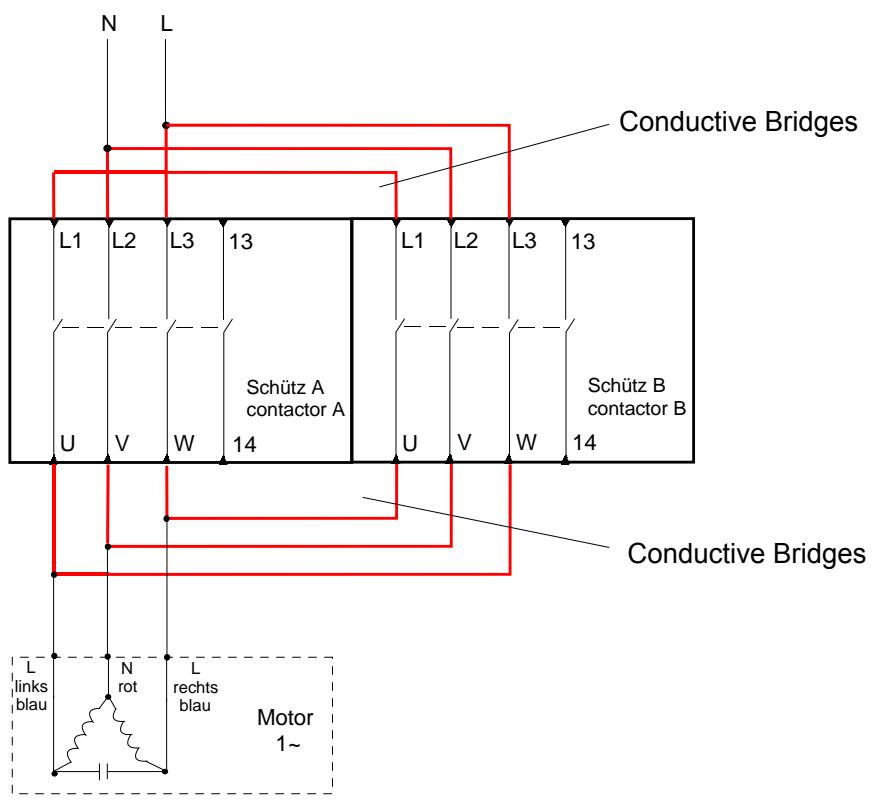
Connection of single-phase drive
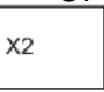
The single-phase drive has to be connected to the screw terminals X2, OPEN, N, CLOSED
Change of sense of rotation: after connecting the drive, the sense of rotation must be checked with the key buttons OPEN and CLOSED. If the moving direction does not correspond to the direction of the arrow indicated on the pressed button, so the screw terminals of the connections OPEN and CLOSED must be exchanged.
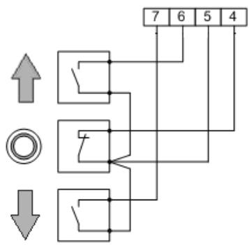
Connection of the external instructions switches OPEN, STOP, CLOSED
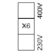
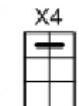
To operate from outside, a triple switch (such as DI 3K) can be connected to the screw terminals X3, 4, 5, 6, 7. Optionally, a triple switch can be connected to through the screw terminal X4. If the block of binding posts is not configured, so a jumper must bridge the stop contact.
The line of external instruction devices must be installed safe according to protective earthing (double insulation).
Here both key buttons related to OPEN and CLOSED should be executed as closer. As the key button related to stop in the safety circuit is already configured, it must be connected as opener.

The area of danger must be visible since the dead-man operation mode runs with key buttons.
Connection of limit switch
The limit switch and safety limit switch OPEN and CLOSED should be connected to the screw terminals 8, 9, 10.
Connection of direct safety switches
- Safety elements that directly intervene in the control process are to be connected in range to the stop contact.
There are, among others: emergency shut-down respectively safety-catch, feed protection and protection of integrated door.
Technical data AS2-eco
Distribution voltage
Current consumption
Safety fuse
Data of relay contact
Rupturing capacity
Mechanical useful life
Electronic useful life
230V - 240V AC / 50 - 60 Hz
max. 120 ~mA
secondary 250 ~mA
Ambient temperature
Humidity
Position of installation
10 × 10^6
10 × 10^6
5^ .55^
45 to 85% RH
as wished
BETRIEBSANLEITUNG / OPERATING INSTRUCTION / MANUEL D'INSTRUCTIONS
Jumper Position AUF/Open/OUVERT
Selbsthaltung
Self Locking
Automaintien
Jumper Position ZU/CLOSE/FERME
Totmann
Hold to run
Homme-mort

ZU
CLOSE
FERME


7 6 5 4
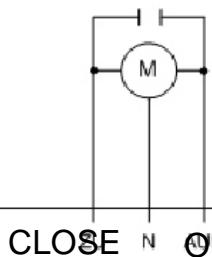
Motor 230V/50Hz-60Hz
CLOSE N OPEN


CHAMBERLAIN
HUBKRAFT MIT PRAZISION
Door control system AS 210
Tested according to:
connected with EN12453
(safety use of power operated doors)

The control AS 210 is conceived to operate doors.
In the basic model, it is made for the dead man operation.
By means of plug-in modules, it can be extended individually.
SAFETYNOTICES
Please note valid directions and regulations of start-up of power operated doors in your country.
Installation and maintenance works at control AS 210 should only be done by skilled Electricians.
Note protecting prescriptions!
The installation has to be switched on free of tension during electrical works
Dead-man operation is only allowed if the installation can be seen from the control devices.

If you do not respect the safety notices, you are responsible of resulting personal and material damages.
CURRENT SUPPLY
In case of fixed connection, an all-polo main switch has to be foreseen.
In case of rotary current, only use triple block safety cut-out (10 A).
Please note that supply voltage corresponds with the data on type plate.
Please note that a clockwise rotatory field should be at the power outlet
Command and control should only be assembled inside buildings.
TECHNICAL DATA
Model AS 210
Tension 230V or 400V
Frequency 50 Hz
Type of protection IP 54
A max. 10 A
Operating temperature -10°C to +55°C
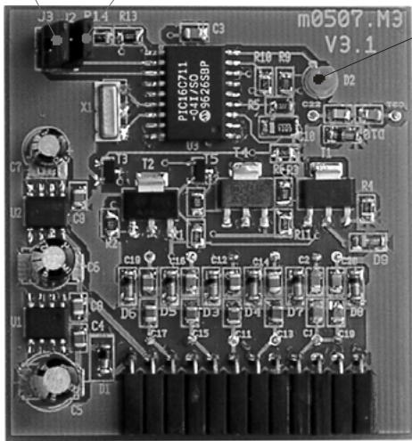
MOTHERBOARD AS 210

CIRCUIT DIAGRAM AS 210 230V FOR OPTOELECTRONIC RUCTURING STRIP AND FOR 8,2 kOhm EVALUATION OF RESISTANCE
*only in connection
with ZM-SKS
ZM-SKS
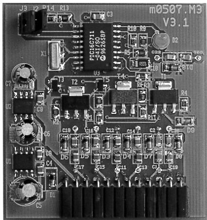
Module for the connection of a SKS rail
Assembling Instructions in Board Plate AS 210:
Insert board plate ZM-SKS in plug-in rail X7. Equipped side must show to the direction of the transformer.

J3 - Jumper
SKS choice
J2 - Jumper
Automatic remove downwards
H1 - LED SKS
Jumper J2 – Automatic remove downwards
plugged in =
Automatic remove downwards
open
no automatic remove downwards
Jumper J3 - SKS choice
plugged in =
optoelectronic rupturing strip
open
8,2 kOhm
LED H1-SKS
Permanent illumination = SKS OK
- Flashing = SKS Disturbance
Circuit Diagram/Single-Phase-Drives ~ to Door Control TST
ATTENTION
In accordance with EN12453, chapter 5.2.9. this circuit (logic board) has to be provided with a grid-disconnection device which can be secured against unintentional engaging
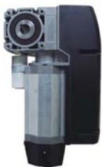
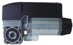
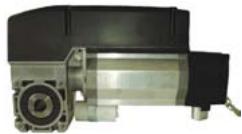
Chamberlain-Garog base set drives include the ready-wired door drive and a torque bracket.
Two base types of drives are available:
- Drive with a potential-free cam limit switch LSS-6 for using external automatic control units or with controller AS210 and ZM-SKS*
- Drive with a controller AS2-eco with a cam limit switch LSS-4 and pre-wired 3-push-button-station.
Various types of emergency actuators are available:
The emergency hand-crank (WKK), the automatic emergency chain (WKN) as well as the quick-action clutch (WKS).
*Operator with integrated Controller AS210 and ZM-SKS are special versions on request
| Model | Typ | Controller | Limit Switch | Nm | Rpm | Emergency Actuation |
| WKK 070190130 | WKK | AS2-eco | LSS-4 | 70 | 19 | Hand crank |
| WKN 070190000 | WKN | -------- | LSS-6 | 70 | 19 | Chain |
| WKN 070190130 | WKN | AS2-eco | LSS-4 | 70 | 19 | Chain |
| WKN 070190440-CN | WKN | AS210 | LSS-6 | 70 | 19 | Chain |
| WKS 070190000 | WKS | -------- | LSS-6 | 70 | 19 | Quick Release Clutch |
| WKS 070190130 | WKS | AS2-eco | LSS-4 | 70 | 19 | Quick Release Clutch |
| WKS 070190440-CN | WKS | AS210 | LSS-6 | 70 | 19 | Quick Release Clutch |
Technical Data
Motor power 0,37 kW
Torque 70Nm
Speed 19 UpM
Duty factor S3 25%
Operating voltage 230V/1~
Frequency 50 Hz
Nominal current 4,8 A
Type of motor protection IP 54
Supply cable, on site 5 × 1,5 ~mm
Fuse protection, on site 10 A
Temperature range -20° - +60°
Hollow shaft 25,4 mm
Weight DKK/DKS 13kg, DKN 15kg
Definition of qualified personnel
Within the meaning of the operating manual and the warning information concerning the product itself, these are people who are familiar with the setting out, installation, commissioning and operation of the product and have suitable qualifications for their work, such as:
a. Training or instruction in, and authorization to connect up, switch on and off, earth and mark power circuits and devices according to the engineering safety standards.
b. Training or instruction according to engineering safety standards in the care and use of the appropriate safety equipment.
c. Training in first aid.
The fitting of drive elements
The fitting of drive elements such as rope pulleys, wheels etc is best done after previous warning of the respective part. The preheating temperature should be 100^
A precoating of a copper paste eases mounting and provides long-term protection from frictional corrosion.
To avoid damage to bearings, housings and shafts the drive elements must never be mounted on the end of the shaft by hammer blows.
The fitting of drive elements by means of pressure requires a force introduction surface (seating on output shaft).
Fitted transmission elements must be counterbalanced and must not cause any non-permitted radial or axial forces.
The corresponding tolerances must be observed during the fittings work (see dimension drawing).
EU Conformity Declaration
(pursuant to EU Machine Guideline 98/37/EG, Annexe II, Part B)
Messrs
Chamberlain GmbH
herewith declares that the products designated below of types:
WKN070, WKK070, WKS070, WKAN070
meet the requirements set out in the following CE guidelines:
EU Machine Guideline 98/37/EG
- EU Low Voltage Guideline 73/23/EWG
- EU Electromagnetic Compatibility Guideline 89/336/EWG.
The following standards were applied:
ZH 1/494 -04/1998
EN 12604 - 08/2000
EN 12453 -02/2001
Doors/Gates - Mechanical Aspects, Requirements
Usage Safety of Power-Driven Doors/Gates, Requirements
Safety of Electric Devices
Functional Safety
Electromagnetic Compatibility
Electromagnetic Compatibility
Electromagnetic Compatibility
Electromagnetic Compatibility
Saarwellingen,
Germany, 5th May 2006
CE
fang Qeena Dipl.-Ing. Harry Naumann Manager, Regulatory Affairs
TABLEAU RELATIF AUX PROTECTIONS ANTI-ECRASEMENT
5^ .55^
Humidité de l'air
Jumper Position AUF/Open/OUVERT
Selbsthaltung
Self Locking
Automaintien
Jumper Position ZU/CLOSE/FERME
Totmann
Hold to run
Homme-mort

ZUCLOSEFERME


7 6 5 4
CHAMBERLAIN
GAROG
HUBKRAFT MIT PRAZISION
Commande deporte AS 210
Contrôls selon: