
SLY500-24 - Garage door opener CHAMBERLAIN - Free user manual and instructions
Find the device manual for free SLY500-24 CHAMBERLAIN in PDF.
User questions about SLY500-24 CHAMBERLAIN
0 question about this device. Answer the ones you know or ask your own.
Ask a new question about this device
Download the instructions for your Garage door opener in PDF format for free! Find your manual SLY500-24 - CHAMBERLAIN and take your electronic device back in hand. On this page are published all the documents necessary for the use of your device. SLY500-24 by CHAMBERLAIN.
USER MANUAL SLY500-24 CHAMBERLAIN
AT/BA/BE/BG/CH/CY/CZ/DE/DK/ES/
FR/GB/GR/HR/HU/IE/IS/IT/LU/MT/NL
NO/PL/PT/RO/RU/SE/SI/SK/TR/YU
Magnet A (1) = links
Manager, Regulatory Affairs
Chamberlain GmbH
D-66793 Saarwellingen
August, 2008


INSTRUCTIONS IMPORTANTES POUR LE MONTAGE ET L'UTILISATION
VEUILLEZ TOUT D'ABORD LIRE CES REGLES DE SECURITE IMPORTANTES

This safety alert symbol means "Caution" - failure to comply with such an instruction involves risk of personal injury or damage to property. Please read these warnings carefully.
This gate drive mechanism is designed and tested to offer appropriately safe service provided it is installed and operated in strict accordance with the following safety rules.
Incorrect installation and/or failure to comply with the following instructions may result in serious personal injury or property damage.

When using tools and small parts to install or carry out repair work on a gate exercise caution and do not wear rings, watches or loose clothing.

It is important to make sure that the gate always runs smoothly. Gates which stick or jam must be repaired immediately. Employ a qualified technician to repair the gate, never attempt to repair it yourself.

Installation and wiring must be in compliance with your local building and electrical installation codes. Power cables must only be connected to a properly earthed supply.

Keep additional accessories away from children. Do not allow children to play with pushbuttons or remote controls. A gate can cause serious injuries as it closes.

Any entrapment possibility by the moving wing between wing & walls must be secured with safety edges or IR-sensors.

Disconnect electric power to the system before making repairs or removing covers.

Please remove any locks fitted to the gate in order to prevent damage to the gate.
A disconnecting device must be provided in the permanently-wired installation to guarantee all-pole disconnection by means of a switch (at least 3mm contact gap) or by a separate fuse.

After the installation a final test of the full function of the system and the full function of the safety devices must be done.

Make sure that people who install, maintain or operate the gate drive follow these instructions. Keep these instructions in a safe place so that you can refer to them quickly when you need to.

This drive cannot be used with a gate incorporating a wicket door unless the drive cannot be operated with the wicket door open.

The full protection against potential squeeze or entrappment must work direct when the drive arms are installed.
Contents: General Information on Installation and Use:
Details of Contents: Page 1 Before You Begin: Page 2
Check List: Page 2, fig1 - 2
Overview of Installation: Page 2
Installation of Rack Bar:
Page 2, fig. 5
Installation of Base Plate:
Page 2, fig. 4 A B
Mounting Drive on Base Plate:
Page 2, fig. 4 | C
Drive Release Mechanism:
Page 2, fig. 6
Limit Switches: Page 2, fig. 7 + 10
Initial Operation:
Page 3, fig.10
Maintenance Work: Page 3, fig. [9]
Technical Data: Page 3
CE Conformity Certificate: Page 3
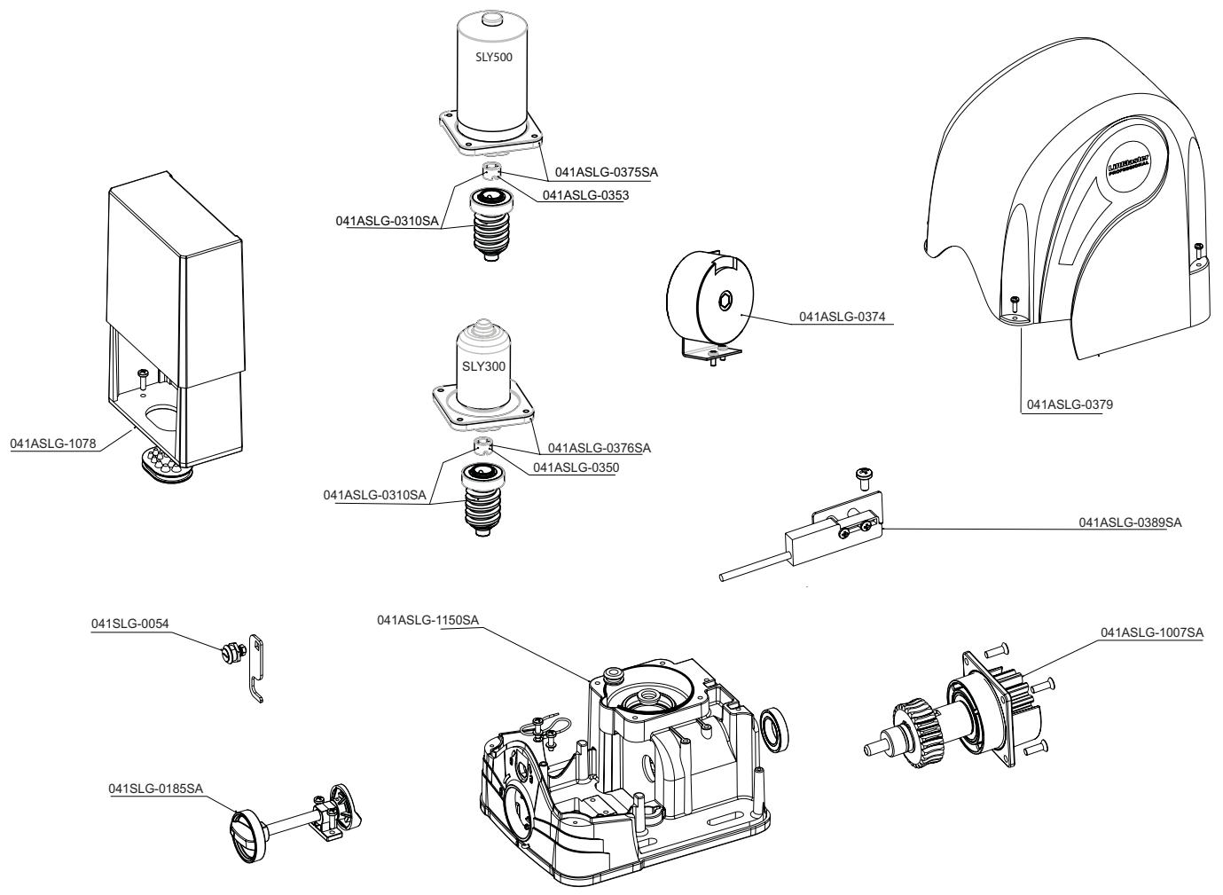
Replacement Parts: fig. 11
Contents in SLY300-24, SLY500-24
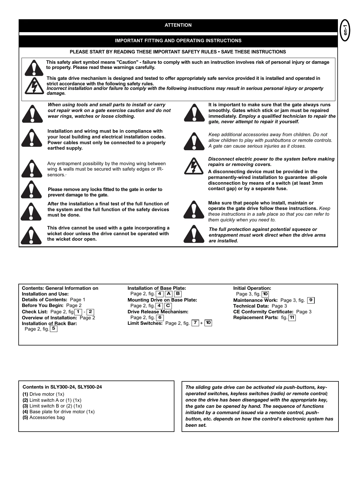
(1) Drive motor (1x)
(2) Limit switch A or (1) (1x)
(3) Limit switch B or (2) (1x)
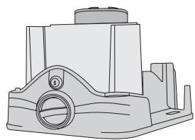
(4) Base plate for drive motor (1x)
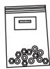
(5) Accessories bag
The sliding gate drive can be activated via push Buttons, key-operated switches, keyless switches (radio) or remote control; once the drive has been disengaged with the appropriate key, the gate can be opened by hand. The sequence of functions initiated by a command issued via a remote control, push-button, etc. depends on how the control's electronic system has been set.
BEFORE YOU BEGIN
There are many factors that are key to the choice of the right sliding gate drive. Assuming the gate is in good working order, the most difficult aspect is getting the gate to move. Once the gate is in motion, force requirements are in the main significantly reduced.
- Gate size: Gate size is a very important factor. A light yet long gate (long = +5m) needs a far greater force to set it in motion than a short, heavy gate does.
WIND CAN BRAKE A GATE'S MOVEMENT OR MAKE IT HARD TO MOVE, THUS INCREASING FORCE REQUIREMENTS SIGNIFICANTLY.
- Gate weight: Gate weight is only an approximate indicator the actual relevance of which can vary greatly. Example: A light gate that slides poorly is likely to need a stronger drive than a heavy, smooth-sliding gate.
- Temperature: Low outdoor temperatures make it difficult or, in some cases, impossible to get the gate moving due, for instance, to changes in the ground conditions. In such cases, a stronger drive again might be necessary. High outdoor temperatures can cause the thermal protection mechanism to be activated sooner.
- Operating frequency / Duty cycle: Sliding gate drives have a maximum duty cycle of approx. 30% (e.g. 30% per hour). CAUTION: The drives were not designed to be run for the maximum duty cycle on a regular basis (permanent operation). If the drive gets too hot, it switches itself off until it has cooled down to activation temperature. The outdoor temperature and the gate itself are key factors determining the drive's actual duty cycle
- Safety: A sliding gate drive has to be fitted with a flashing lamp, contact strips and, if necessary, with additional light barriers as safety features. Please ensure that you comply with the standards and regulations relevant to your particular case.
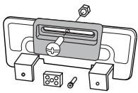
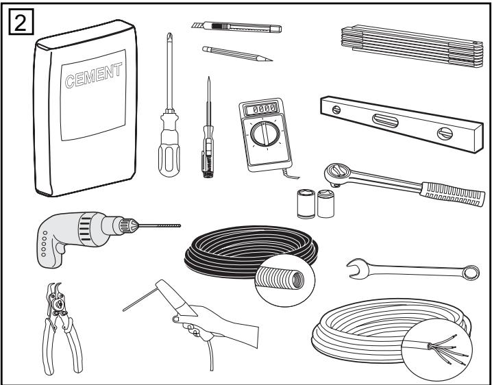
CHECK LIST - PRE-INSTALLATION WORK 1 - 2
Prior to actual installation, please check that you have been provided with all the parts indicated within the scope of supply. 1 Make sure your gate system is in good working order.
The gate must run smoothly, not jerkily and not make contact with the ground at any point. Bear in mind that the ground can be several centimetres higher in winter. The gate needs to be stable with as little play as possible to prevent any lateral movement from occurring. The easier the gate moves, the more sensitive the force setting needs to be.
Make a note of the materials you still need and make sure you obtain them prior to installation - adhesive anchors (strong plugs), screws, stops, cable, distributor boxes, tools, etc. 2
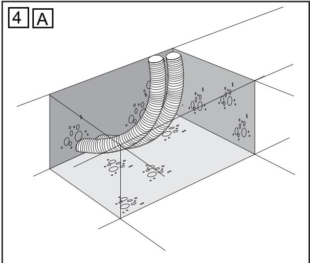
OVERVIEW OF INSTALLATION 3-5+10
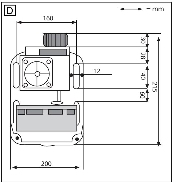
The drive has to be installed behind the wall to ensure that no part of it projects out into the gate opening. The motor has to be mounted on the flush fitted base plate. The rack bar shown has to be fitted to the gate with the fixing material supplied.
Decide which is the best height for fixing the rack bar to the gate and use this to determine the installation dimensions for the motor unit and base plate. Should the gate be unsuitable for fitting the rack bar to it, a fixing profile (angle bracket, shaped tubing, etc.) needs to be mounted first.
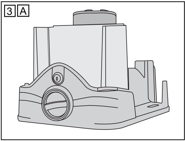
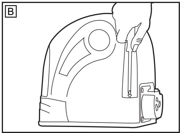
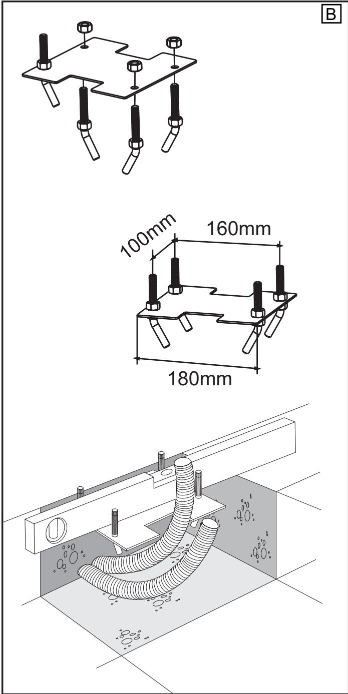
INSTALLATION OF DRIVE BASE PLATE 4 A + B
The base plate for the drive can either be concreted in or, if appropriate, welded into position. The place where the base plate is usually located is shown on the installation overview. The concrete plinth needs to be of an appropriate size (approx. 50cm× 50cm× 50cm ).
Please note: If it is impossible to precisely determine the height of the plinth and the distance from the gate prior to installation, it is advisable to mount the rack bars first and then concrete in the base plate. Spacers are fitted to move the rack bars approx. 40mm towards the inside.
The distance from the bottom edge of the rack bar to the base plate is approx. 8 - 9cm. The base plate permits final height and depth adjustments of several centimetres to be made, but you are advised to work as precisely as possible from the outset.
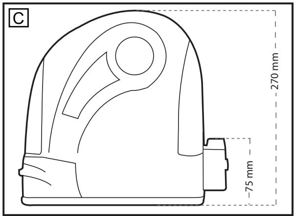
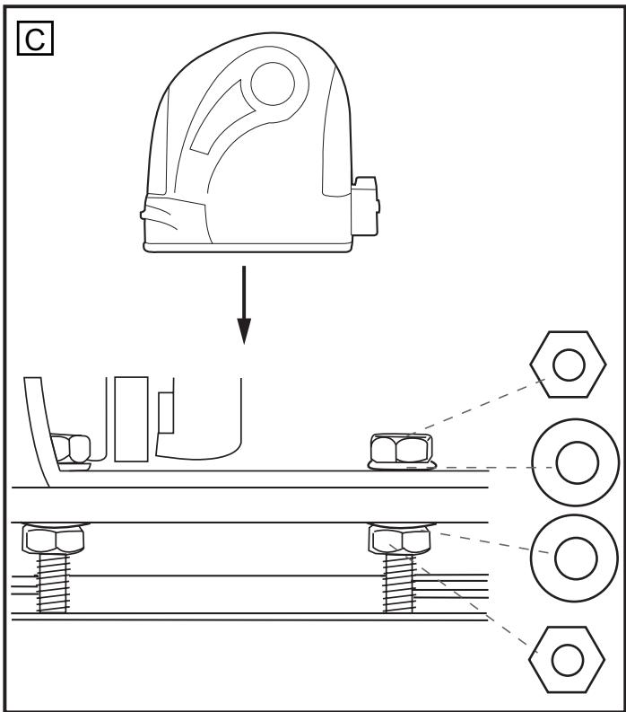
MOUNTING MOTOR AND GEAR UNIT 4 C
The drive should be fitted on to the threaded bolts in the base plate. The height should be set such that there is a gap of approx. 1 - 2mm between the cog wheel and the rack bar. The weight of the gate should not be borne by the cog wheel! Position the drive via the adjustment holes such that its location vis-à-vis the rack bar complies with the installation dimensions.
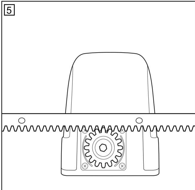
MOUNTING RACK BAR 5
The easiest way to fit the rack bar is to first place it on the motor's drive cog, disengage the motor and, by pushing the gate further with the rack bar, screwing the bar bit by bit firmly in position. In this way, you ensure that the rail bar engages with the cog wheel in an optimum manner. While doing this, do not forget to mark each fixing point.
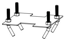
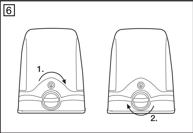
DRIVE RELEASE MECHANISM (MANUAL OPERATION) 6
The drive is equipped with a lockable release mechanism to enable the gate to be operated manually in a power cut. The release mechanism is shown in fig. 6 with the clutch disengaging the link between the cog wheel and the gear.
To release the drive: Position the socket spanner appropriately and turn it 180 degrees. Then turn the release lever 180 degrees too. Finished.
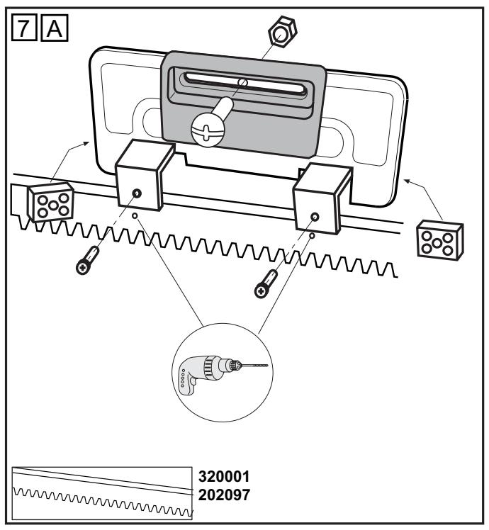
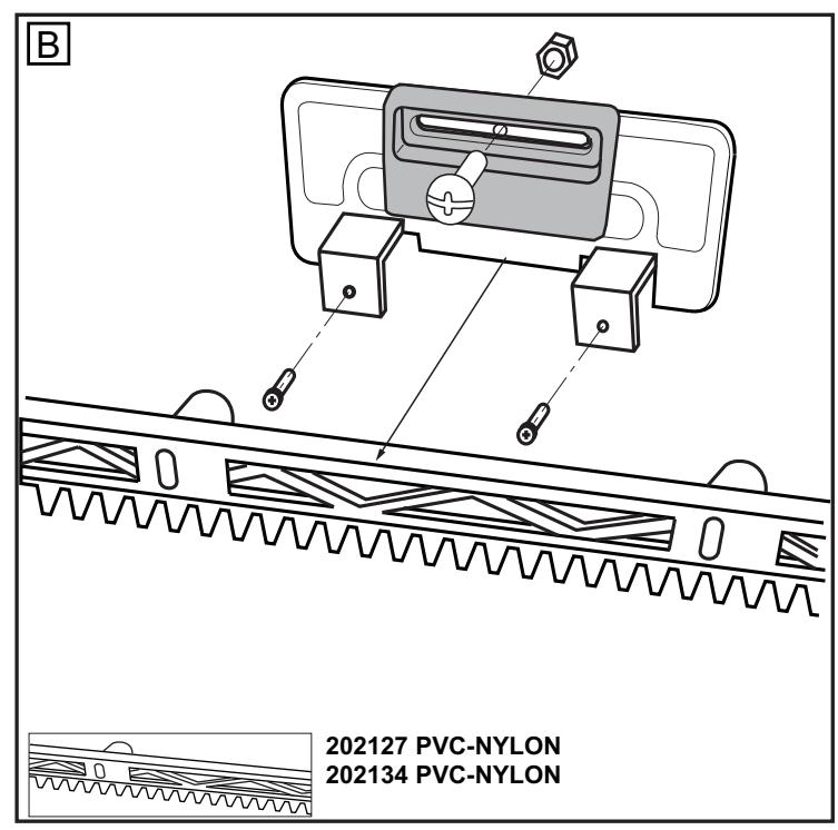
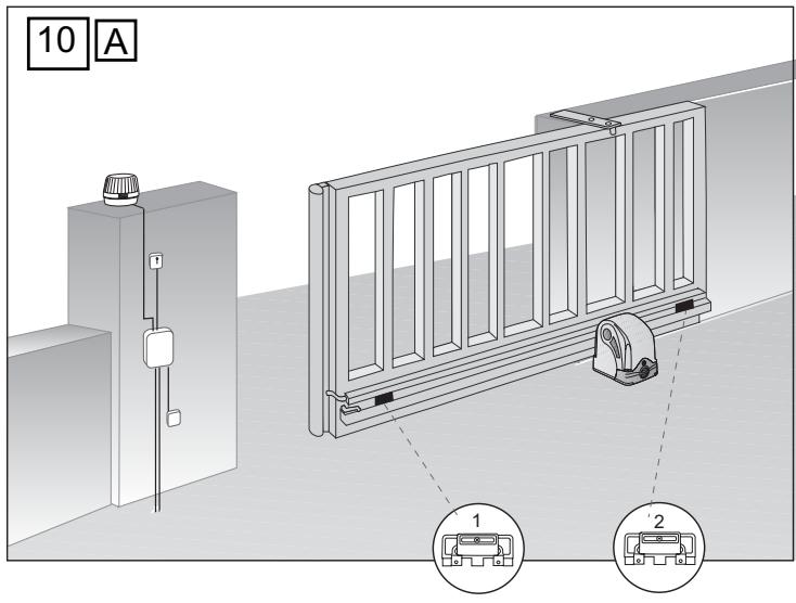
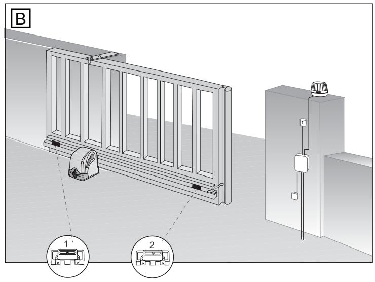
FITTING LIMIT SWITCHES (TO GATE) 7 +10
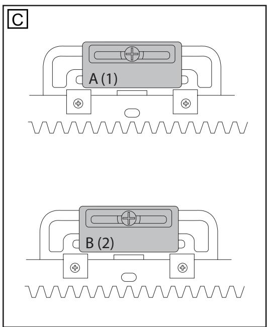
The limit switches are assembled as shown in fig. 7A-C, 10A+B. One limit switch magnet is designated A (1) and the other B (2).
Fit the limit switches on to the rack bar in those places where the final travel positions are roughly expected to be. The magnet should point towards the motor. The switch (contact) is located in the middle of the motor. Screw the retaining clip only provisionally in place or slot it lightly on to the rack bar.
Caution: Please notice fitting of the magnets on the rack bar (fig. 10A+B)
Magnet A (1) = to the left
Magnet B (2) = to the right
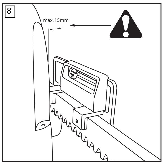
Caution: A sliding gate must run in a guide rail and should not be able to leave the rail. This means end stops need to be fitted for both directions!
TECHNICAL DATA
| SLY300-24 | SLY500-24 | ||
| Voltage IN | VAC | 220 - 240 | 220 - 240 |
| Voltage OUT | VDC | 24 | 24 |
| Power | W | 40 | 60 |
| Current (max) | A | 5 | 6 |
| Torque | Nm | 10 | 15 |
| Motor Speed | RPM | 2500 | 2200 |
| Travel Speed | cm/s | 14 | 12 |
| Duty Cycle | Zyklen/h | 50 | 50 |
| Working Temperatur Range | °C | -20°C/+55°C | -20°C/+55°C |
| Protection Class | I | I | I |
| Degree of Protection | IP | 44 | 44 |
| Weight | Kg | 8 | 8 |
| approx. Gate Length | m | 5 | 8 |
| Max. Gate weight at max. length (incl. 20% reserve) | Kg | 300 | 500 |
INITIAL OPERATION
Check gate functionality manually when the drive has been disengaged. Electrical operation is only possible with the control unit that is supplied as standard.
Electrical connections: See control unit instructions.
Always ensure that the mechanical and electrical safety requirements relevant to the given system are complied with. fig. 8
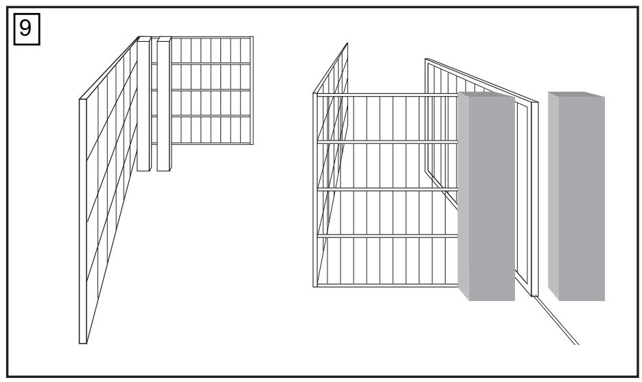
MAINTENANCE WORK
The drive mechanics are maintenance-free. Check at regular intervals (monthly) that the gate hardware and the drive are all firmly in place. Disengage the drive and check gate functionality. Only an easy-running gate will work well with a drive. A drive is no substitute for a poorly functioning gate.
A sliding gate can also be secured by implementing on-site measures (fence, wall, etc.). See fig. 9.
Declaration of Conformity
Automatic Gate Opener Models SLY300-24, SLY500-24 Series
are in conformity to the applicable sections of StandardsEN300220-3 • EN55014 • EN61000-3 • EN60555, EN60335-1 • ETS 300 683 • EN60335-1: 2002 • EN60335-2-103: 2003 • EN55014-1: 2000 + A1 + A2 • EN55014-2: 2001 • EN61000-3-2: 2000 • EN61000-3-3: 1995 + A1 • EN 301 489-3, V1.3.1 • EN 300 220-3 V1.1.1 • EN13241-1
per the provisions & all amendments of the EU Directives 2006/95/EC, 2004/108/EC, 1999/5/EG
Declaration of Incorporation
Automatic Gate Opener Models, when installed and maintained according to all the Manufacturer's instructions in combination with a Gate, which has also been installed and maintained according to all the Manufacturer's instructions, meets the provisions of EU Directive 89/392/EEC and all amendments.
I, the undersigned, hereby declare that the equipment specified above and any accessory listed in the manual conforms to the above Directives and Standards.
B.P.Kelkhoff
Manager, Regulatory Affairs
Chamberlain GmbH
D-66793 Saarwellingen
August, 2008


IMPORTANT ISTRUZIONI PER IL MONTAGGIO E L'USO
PER PRIMA COSA LEGGERE QUESTE IMPORTANTI NORME DI SICUREZZA!


The easiest way to fit the rack bar is to first place it on the motor's drive cog, disengage the motor and, by pushing the gate further with the rack bar, screwing the bar bit by bit firmly in position. In this way, you ensure that the rail bar engages with the cog wheel in an optimum manner. While doing this, do not forget to mark each fixing point.
AANDRIJVING ONTGRENDELEN (HANDBEDIENING) 6
Magneet A (1) = links
Manager, Regulatory Affairs
Chamberlain GmbH
D-66793 Saarwellingen
August, 2008


DULEZITE POKNY K MONTAZI A POUZITI
ZACNÉTE TÍM, ZE SI PRECTETE TATO DÜLEZITÁ BEZPEÇNOSTNÍ PRAVIDLA

Manager, Regulatory Affairs
Chamberlain GmbH
D-66793 Saarwellingen
August, 2008


Manager, Regulatory Affairs
Chamberlain GmbH
D-66793 Saarwellingen
August, 2008

BaIbIa P.KeckhoH
VAZEN UPUTE ZA MONTAZU I KORISTENJE
ZAPOCNISE S CITANJEM OVIH VAZNIH SIGURNOSNIH UPUTA

Ovi simboli upozorenja označavaju rijec "Pažnja!", poziv za obracanje pažnje, jer njihovo nepostivanje要考虑 prouzrokovati ostecenje ljudskog zdravlja ili materijalnu štetu. Molimo da pročitate ova upozorenja pažljivo.
Ovaj pogonski mehanizam za kapiju konstruiran je i testiran takdo prilikom instalacije i upotrebe uz tocno poštivanje pravila bezbjednosti osigurava primjerenu bezbjednost.
Manager, Regulatory Affairs
Chamberlain GmbH
D-66793 Saarwellingen
August, 2008


WAZNE WSKAZOWKI DOTYCZE MONTAZI WYKORZYSTANIA
NA POCZATEK NALEZY ZAPOZNAĆ SIE Z NINIEJSZYMI WAZNYMI ZASADAMI BEZPIECZEÑSTWA

INFORMACJE POCZATKOWE
2006/95/EC, 2004/108/EC, 1999/5/WE
Manager, Regulatory Affairs
Chamberlain GmbH
D-66793 Saarwellingen
August, 2008


BAXHbIe YK3AHnI PO MOHTAXU IcNoJIb3OBAHIO
HACHNTE C IPOUTEHIN 3TINX BAXKbIX IPIPABNJ TEXHNI K E3OJNACHOCTN


3Tn npEynpexkaioune cHMBOJI bO3HaayoT "BHHMaHne", oBaIeHne K BaIeMy BHHMaHIO, taK KaKnx Hec6bIHOeHne MorJIo 6bl npUHNHTBpeD 3dOpOBbIy YelOBeka IIIM MaTePnaIbHbI yIep6.
Ioxaynyucta, BHMaTeNbHO npOHTaTE 3TN npEynpeXeHn.
Данньй ппвор БОРТСКОНСТурOBAH И OTТСТИРOBAH TAKIM OБразим,ЧTOбы ппс CBоe YCTAHOBKe И NCПОЛБОВАHи (пп рочHom COБЛЮDEни павил ТхнКи 6e3ONaCHOCTи) ON ppeIOCTaBЯн 6bl NOЛьЗОВATEJIО OTHOCHTeNBHyю 6e3ONaCHOCTb.ИTOROM HeCObLIODEня HactOуцnx павил TхнКи 6e3ONaCHOCTn MOKet 6blTb BpeI, ппчнEHьь 3dopoBBJO LIOdeи mATEpnaJBьь yuEp6.

Ipu MaHunyIaIcuaX c UHCmpymeHmAmu u MeKumU yacmMa deuecmeyume c ocmopoxhocmbu u He Hocume KOnbua (nepcmHu), yacbU c6o6oHyIO odexdy (ecnHa eopomax ocyuememra pabombI no ux ycmaHOeke u peMoHmy).

3JektpoPoBOKy Heo6xOdMn POkJaIbIbA Tb B COOTBeTCTBm C MeCTHbIMN CTPOITeJIbHbIMN HOpMaMn INHCTpyKUmaM, OTHOCaUIMMCr K 3JekTpOPOBODKe. PIOkJIuOHeNe 3JekTpnuEcKO r Ka6eR N npaBnIbHO 3a3emJeHHo CeTn MoKeT OCyUeCTBnIbT b JInuB abTOPn3OBaHHb pa60THNK - 3JekTpNK.

Ipu MoHmaxe Heo6xOUMo npuHm8 6eHumHue onaChocmb 3axamur MExdy nepemeeaeMoU qacmbEOopom u Okpykaoumu yacmAmu 3daHn, Hapumep: cmHo.

ДлгТOrO,чTO6bI BOCnpeNЯТСТВОВaTБ BO3HnKHOBEHnIO NOBpeJdeHnI,пОжaЛусТа,уДaЛNTe N3 BOPOT BCE BMOHTnPOBaHHbE B HIX 3aMKn.

Iocne yctahOBKn Heo6xOdmo npOBepntb MexaHn3M Ha npaBnIbHocTb ero HacTpoKn, a TaKKe npBOD, cnCTembl 6e3onacHocTn u ABapNHorO OT6nOKnPOBaHnHa npeDmET nx npaBnIbHoro fYHKNUOHnPOBaHn.

EcIn B BOPoTax yCTaHOBJIeHbI DBePn IJy npoxOa,TO npINBOHNO MExAHN3M HeJIb3A3nyCTNTb ININ OCTaBNTb erO BKIIIOUeHHbIM Do Tex nop, NOKA BOPoTa He 6yDyt DOJIKNHBIM O6pa3OM 3aKpbITbl.

Baxho, yTo6bI nepeMeueHne BOpT 6blIO 6blIO nocToHHo rnaKIM. BOpTa, KOToBle 3aklnHrTa nII 6byT 3aeDaTb, Heo6xOIMO HemeIeHNO OTpeMOHTnpOBaTb. He np6yIte pemOnTIpoBaTb BOpTa cam. ObpaNTecb 3a IomouIbIO K cneuHaNtCy.

Донон'teььные устpoctBa pa3mectiteТak,чTOбыОи He 6bln DoCTynbI DeTAM. He no3BOJnTe DeTAM,чTOбы OHI MaHInyIpOBaJI N C KHOtKamN I nDuctaHcIOHHbIM ynpaBHeHem. 3akpbBaIOUneecr BOPota MOrY npuHnHb TЯжелble paHeHn.

Ipu ocyuemeenu pa6om no yxody, Hapumep: npu ouucmke, aemomamueecku ynpaenembte ycmpoucmea donxhbl 6bimb omknnoehbl u3 cemu 3nekpmunumanu.
YJxctKo NOdkJIIOUeHHo 3JeKTpOPOBOODKn Heo6XoDMIO NOMHnTb 06 yCTPoiCtBE pa3MbIKAHNa DnTo rTO, YTO6bl BO BcEx nONJx OTKlHOeHn6blO bbl rapaHTnpOBaHO OTKIoUeHne npi NOMOu NipeKIOUaTeJIa (pa3MbIKAHnE KOHTaKTOB He MeHee 3 MM) nnPi NpN NOMOUs OTdEJIbHorO ppeOxApanTeJIa.

Obecnebyte, YTO6bI Te INaCa, KOToPbIe OcyuIeCTBnIaHOTMOHTaK, yXoD n 06cnyKbAHne npNbOda, co6blOaJIIN Tpe6obAHNA HAcTOnaSeHnCTpyKcH. IVHcmpyKcuio pa3MeCmume b makOM MeCme, 2de 6bI OHa 6bla 6bIcmpo docmynHa.

Iocne MoHmka npuBoda doJnKha 6bImb 6e3ycNoHo oEscneueHa oxpHa Mecm, e Komopbix cyuecmeyem yap03a 6o3HuKnHOeHua yuu6oE u nope3o8.
CoepeKHaHHe:O6uHne yKa3aHnI NO MOHTaKy n 3KcPJIyatauHn:
OrnaBJIeHne: cTp.1
Ipexe, yem Haayatb: ctp.2
KoHTpOJIbHbI cIINcOK: cTp.2,pnc.1 - 2
063op MoHTaxKa: cTp.2
MOnTaX 3y6aToN peKn: cTp.2,pnc5
BHMaHHe! O6paaMaTe BHMaHHe Ha MOHTax MArHnTOB Ha 3y6CuToi peKe (10A+B).
MarHnT A (1) = cJIeBa;
MarHnT B (2) = cnpaB;
BHHMaHHe:Pa3dBnXhIe BOpota DoJXhIe nepMeaTbcR B BbIHyKJeHHompeXmE, t.e. He MoKeT 6bITb TaK, YTO6bI BOpota CXOJIIN C HAnpaBnIauxN. Ppi DnXkeHIn BOpOT B O6oNX HAnpaBLeHnx DoJXhBI 6bITb IpeDycmOTpeHbOrpaHnHTeIN XoJa.
TEXHNUCKNE XAPAKTEPNCNIK
Manager, Regulatory Affairs
Chamberlain GmbH
D-66793 Saarwellingen
August, 2008

Dabbaia P. KeckhoH
SLY300-24/SLY500-24
11
SPARE PARTS
NOTES: