
OF 500 S - Drill AEG - Free user manual and instructions
Find the device manual for free OF 500 S AEG in PDF.
| Product type | Router |
| Brand | AEG |
| Model | OF 500 S |
| Power input | 500 W |
| No-load speed | 34,000 min⁻¹ |
| Maximum rotation speed (without limitation) | 39,000 min⁻¹ |
| Milling stroke | Not specified (adjustable by revolver stop) |
| Clamping collet diameter | 6 mm, 8 mm, 1/4" |
| Cutter diameter (HSS/HM) | Up to 38 mm (softwood, chipboard, plastic) |
| Weight | 2.9 kg |
| Power supply | Single-phase, voltage according to rating plate (double insulation) |
| Noise level (sound pressure) | 82 dB(A) |
| Noise level (sound power) | 95 dB(A) |
| Measured vibration value | 4 m/s² |
| Main functions | Groove milling, rounding, chamfering, edges; use as die grinder |
| Parallel stop | Yes, gap up to 240 mm |
| Depth stop | Yes, with revolver stop for 3 depths |
| Switch | Slide switch with lock |
| Maintenance | Clean ventilation openings; annual brush check by an AEG service center |
| Spare parts and repairability | Use only AEG accessories; exploded view available on request |
| Compatible accessories | Flexible shaft, curve cutting guide, guide bar, template sleeve, protective glass |
| Safety | Double insulation (DIN 57 740/VDE 0740, CEE 20); interference suppression EN 55014 |
| Intended use | Wood and plastics; milling and grinding work |
Frequently Asked Questions - OF 500 S AEG
User questions about OF 500 S AEG
0 question about this device. Answer the ones you know or ask your own.
Ask a new question about this device
Download the instructions for your Drill in PDF format for free! Find your manual OF 500 S - AEG and take your electronic device back in hand. On this page are published all the documents necessary for the use of your device. OF 500 S by AEG.
USER MANUAL OF 500 S AEG
| Introduction | You are demanding and expect to purchase quality goods - quality offered by Atlas Copco. We have built a durable and reliable electric power tool for you. Please read the instructions for use before first operation so you can handle your power tool effectively and safely. We are sure that buying an AEG Electric Power Tool from Atlas Copco was the right choice! |
| Technical Data | OF 500 S OFE 710 Nominal power 500 W 710 W No-load speed 34 000 min-1 30 000 min-1 Maximum no-load speed in case of ineffective no-load speed limitation - 39 000 min-1 Cage stroke 50 mm 50 mm Collet diameter 6 mm, 8 mm, 1/4** 6 mm, 8 mm, 1/4** Router diameter (HSS/HM) max. 36 mm max. 36 mm Abrasive grinding body diam. max. for ceramic resin 20 mm 20 mm for plastic resin 38 mm 38 mm Gear neck diameter 43 mm 43 mm Weight 2,9 kg 2,9 kg *Not included in standard equipment, available as an accessory. |
| Advice for your safety | Please pay attention to the safety instructions in the attached leaflet! Always use the protective shields on the machine. Always wear goggles when using the machine. It is recommended to wear gloves, sturdy non-slipping shoes and apron. Sawdust and splinters must not be removed while the machine is running. Do not pierce the motor housing as this could damage the double insulation (use adhesives). Always disconnect the plug from the socket before carrying out any work on the machine. Only plug-in when machine is switched off. Keep mains lead clear from working range of the machine. Always lead the cable away behind you. Only use professionally grinded router cutters. All inserted tools which are used must be admitted for the max. speed of rotation! The workpieces should be clamped down before cutting. Put the router back to original position after usage (loosen clamping lever to secure cage). After switching off, the machine will not be idle immediately. (After-running of the work spindle.) Only move the workpiece in counter rotation to cutter (only work oppositely oriented)! For security, use devices such as safety- and pressure device, guide slide, rip fence, etc. For ceramic abrasives or silicone rubber polishers with a safe peripheral speed of 45 m/s, the grinding body diameter must not exceed 20 mm. With synthetic resin plastic abrasives with a safe peripheral speed of 80 m/s, the grinding body diameter must not exceed 38 mm The dust that arises when working with this tool can be detrimental to health (e.g. when working oak or beach wood, stones, paint, which could contain lead or other harmful chemicals) and therefore not reach the body. Use a dust absorption system and wear a suitable dust protection mask. Remove deposited dust thoroughly, e.g. with a vacuum cleaner. |
| Measured sound value | Typically the A-weighted noise levels of the tool are: Sound pressure level = 82 dB (A). Sound power level = 95 dB (A). Wear ear protectors! |
| Measured vibration value | Typically the weighted acceleration is 4 m/s2. |
| Mains connection | Connect only to a single-phase AC current supply and only to the mains voltage specified on the rating plate. Connection to sockets without earth protection is possible as the appliance features protective insulation to DIN 57 740/ VDE 0740 and CEE 20. Radio suppression complies with the European standard EN 55014. When fitting the plug, make sure that the brown (live) wire of this appliance is |
| ENGLISH | 1 OF 500 S, OFE 710 |
| connected to the plug terminal marked L or coloured red, and the blue (neutral) wire of this appliance is connected to the plug terminal marked N or coloured black. Under no circumstances must the wires of this appliance be connected to the earth terminal of the plug marked either E, with the earth symbol or coloured green or green/yellow. | |
| Use | The router can be used for rabbeting, rounding off, chamfering, routing of edges, as well as pitting in wood and plastic. The router can additionally be used as a straight grinder and in combination with a flexible shaft (accessory). Do not use this product in another way as stated for normal use. |
Brief description
Exchanging router cutters

Always disconnect the plug from the socket before carrying out any work on the machine.

The collet diameter must be corresponding to the shaft diameter.
nset the shaft of the tool as far as possible into the collet and tighten with clamping nut.
To take out router cutter, loosen adjusting nut until the cutter can be removed.
| Exchanging collets | The following collets can be used:ø 6 mm,ø 8 mm,ø 1/4"* (Theø relates to the shaft diameter of the router). | |
| 1. Unscrew adjusting nut completely with collet (see also "Exchanging router cutters". | ||
| 2. Pull out collet from adjusting nut. | ||
| 3. Push a new collet into adjusting nut until it locks into position. | ||
| 4. Screw adjusting nut with collet onto working spindle and tighten. | ||
| Parallel guide | 1. Assembly of parallel guide as shown in illustration. | |
| 2. Insert parallel guide into the bores at the base plate. After setting the required distance from the edge tighten the wing screws. | ||
| For close cutting of boards coated on one or both sides, the plastic corner guides are screwed on, as figure. | ||
| Fine adjustment (Accessory*) Part number: 4932 3115 84) | Insert the precision adjustment screw (B) fromthe right or left into the base plate. Adjust the cutting distance roughly and tighten screw (A). By turning the screw socket set the clearance exactly. Tighten clamping screw. Check the settings with a test cut and make possible corrections with aid of fine adjustment. | |
| Sawdust removal | For sawdust removal, a suction hose can be attached to the suction device of the machine. Industrial vacuum cleaners as well as household vacuum cleaners are suitable. Only operate the machine with suitable sawdust removal. | |
| 1. Insert the suction device as shown in illustration. | ||
| 2. Insert the suction hose into suction device turning it slightly and connect the other end of the hose with a vacuum cleaner. The suction device has a standardized inner diameter of 26 mm. Any suction hose with the same diameter can be used (e.g. suction hose Id-No. 4932 3304 12). | ||
| ENGLISH | 3 | OF 500 S, OFE 710 |
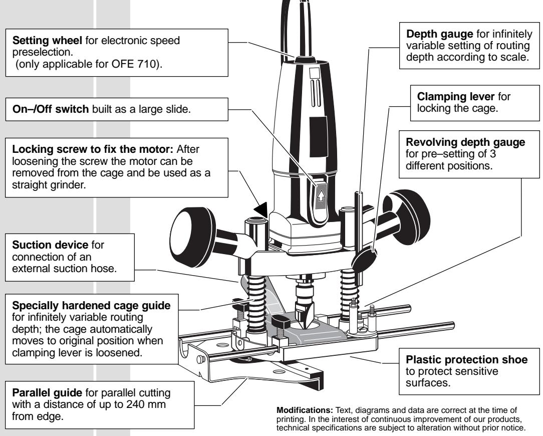
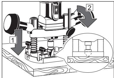
| Setting of routing depth | 1. Lower cage until the router cutter touches the workpiece ①, and tighten clamping lever ②. | ||||
| Revolving depth gauge | 2. Lower the depth gauge onto the required screw of the revolving depth gauge. | ||||
| 3. Pick value off the scale, add required routing depth, and set depth gauge at estimated value ②. | |||||
| 4. Loosen clamping lever, lower cage to depth gauge and re-tighten clamping lever. | |||||
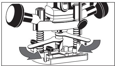
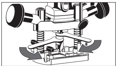
| It is advisable to cut in stages for larger cutting depths or larger cutter diameters. Three cutting depths can be set with the screws on the revolving depth gauge: | |||||
| 1. Set required cutting depths as described above, and set the depth gauge on the shortest screw (lowest cutting level). | |||||
| 2. Set the first two cutting depths on the longer screws. Tighten screws again and secure with the locking nuts against distorting. | |||||
| 3. For cutting, lower the cage to the longest screw and tighten. Turn the depth gauge each time after cutting. | |||||
| Setting speed of rotation (only applicable for OFE 710). Table for electronic settings | A = lowest r.p.m. G = largest r.p.m. Under the effect of extreme electromagnetic interferences from the outside, tempo-rary variations in the speed of rotation could arise in particular cases. | ||||
| Router ① in mm | Router working material | Soft wood | Panels made of wood chips | Plastic, Perspex | |
| 4-16 | HSS | F-G | - | D-E | |
| 18-36 | HSS | E | - | C-D | |
| 4-20 | HM | G | G | E-F | |
| 22-36 | HM | F | F | D-E | |
| On-off switch | Switching on: Slide back the On/Off switch. To lock, depress the front part of the sliding switch. | ||||
| Switching off: To unlock, depress the back part of the sliding switch. The switch will automatically move back to "0". | |||||
| ENGLISH | 4 OF 500 S, OFE 710 | ||||
| Mounting the plastic protection (Accessory* Part number: 4932 3117 22) | Push the plastic protection into base plate as shown in illustration. | ||
| Mounting the flexible shaft (Accessory* Part number: 4932 3300 00) | Loosen the clamping screw of the motor part and remove it from the cage. Fix the motor part in the machine holder (Order No. 4932 3192 27) and fasten the machine holder on the workbench. The machine can also be fixed with the screw clamp (Order No. 4932 3018 06). Fix the flexible shaft in the collet and tighten the tension nut. The machine has a max. speed of rotation of 34 000 min-1. Therefore only use the ball-bearing AEG flexible shaft (Order No. see above). | ||
| Copying device (Accessory* Part number: 4932 2499 77) | For cutting shapes to a pattern (B) the guide bearings (A) must be screwed onto the base plate. For outer contours the pattern (B) must be smaller by measurement (C), on inner contours it must be bigger than the workpiece. Further guide sleeves with an outer diameter of 25-40 mm can be obtained as accessory. | ||
| Curve Gauge (Accessory* Part number: 4932 3132 74) | Unscrew the guide bars from the rip fence and screw onto the curve gauge. | ||
| Circular Guide (Accessory* Part number: 4932 2499 80) | Push the shaft into oneof the drill holes for the rip fence.Set the radius between the central point and profile cutter and tighten the capstan-head screw. | ||
| ENGLISH | 5 | OF 500 S, OFE 710 | |
| Adapter for guide rails (Accessory* Part number: 4932 3618 66) | Unscrew the parallel guide from its guide rails and fix the adapter instead. When the adapter is attached, the router can be lead along the guide rail (accessory). This makes exact cuts possible. | ||
| Advises for operation | Lead the machine steadily over the workpiece, holding it with bouth hands. Always work in counter rotation to cutter (see illustration), otherwise danger of backstroke! For exact straight cutting, use the guide rail. Lenght 800 mm: Order No. 4932 3618 35 Lenght 1400 mm: Order No. 4932 3618 36 After removing the cage, the router can be used as a straight grinder. In connection with the flexible shaft (accessory), it is possible to work in places which are difficult to reach. | ||
| Maintenance | The ventilation slots of the machine must be kept clear at all times. In order to guarantee constant readiness for operation, the machine should be checked for worn carbon brushes at one of the AEG after-sales service agencies. Use only AEG accessories and spare parts. Should components need to be replaced which have not been described, please contact one of our AEG service agents (see our list of guarantee/service addresses). If needed, an exploded view of the tool can be ordered. Please state the ten-digit No. as well as the machine type printed on the label and order the drawing at your local service agents or directly at: Atlas Copco Electric Tools GmbH, Postfach 320, D-71361 Winnenden. | ||
| ENGLISH | 6 | OF 500 S, OFE 710 | |
BbIKIIOUaTeIb BKn./BbIKI. (On/Off) BbIIOJIHeH BnDE 6oJIbWoO nepeKIIIOuHaTeJI.
KoHTpOBoUHbI BnHT IJL4 ΦNkCaUH MOTOpa:PNCleOTBnHcHbAHnBnHTa MOTOP MOKeT 6bITb CHrT C KapeTkn U NCNoJIb3OBaH B KaueCTBe PnpMoI USINΦOBAJIbHOI MaUNHKn.
Φpe3epHa MaunHa MOKeT
NcNoIb3OBaTbCra IJa BbIbOpKn
Na3OB, 3akpyIeHnK KPMOK, ChrTnA
facok n faoconHoro fpe3epoBaHnK
KPMOK, a TAKCe I da CbePeHnB B
depeBe n PJIaCTnke.
CneuJIbNo 3aKaJEnHna HnpaBIAUOua KapeTkn DnI beCCtUneHuTaTO peYIpOBaHNrIy6InbI φpe3ePoBaNcK; KapetKa ABToMaTHueCKn BO3BpAuaeTCR BxCoXDHe POJIOKeHHe, KOrDa 3axmHOn pbHaR OTnyUeH.
IapalneJbHaHnpaBlaIOUaJaI npalpeJIbHOJ o6pa6OToN HaPacCToHHn Do 240 MM OTOKpOMKn.
OrpaHnHTeIb Iy6uHbI
IaI 6ecCTynEHaTOI
yCTaHOBKn Iy6uHbI
fpe3epoBaHnI IO
uKaJe.
3aHpaUoui pbuag
IJIa 0Kcaun
KapeTkn.
DnAmEtP zauHroBOr NaTPOHa DOnJxHe COOTBeCTBOBaTb DnAmEtpy BaJa.
BCTaBbTe XBOCTOBuK INHCTpyMeHTa KaK MOxHO rJyOBe B uAHOBBu NaTPOH N 3aTAYNE pNn NMOUIN 3axMUMOH raIKN.
ДлгТOrO,чTOбыВblHrTbфpe3y, OcnaБtepeRpyIINPOBOUHyOraKу TaK, ChTOбыФpe3y MoXHO bIIO BblHrTb.
| 3aMeHa zauHOBbIX natPOHOB | Mogyt 6bIb ICSNoB3OBAHb CNeDyUOuHc ZauHOBbIe NaTPOHb: 06MM, 08MM, 01/4" (0CooBTCTByET DnAmEtpy Bala ΦpezepHOJ MaunHb). | |
| 1. ПОЛнOCtBu IO TBerHPNte pergyIropOBoHyIO raKy C zauHOBbIM NaTPOHOM (CMOTPHe TakKc "3aMeHa φpe3"). | ||
| 2. ByInbTe zauHOBbIe NaTPOH u3 pergyIropOBoHyO raKbN. | ||
| 3. BCTaBbTe HObI yauHOBbIe NaTPOH B pergyIropOBoHyO raKbY NOKA OH He 3aUeJIKNetCry. | ||
| 4. HabERHNTe pergyIropOBoHyIO raKbY C zauHOBbIM natPOHOm Ha paOchOH mIINHdJIb N 3aTAYHNTe. | ||
| Параллельная нарразьяюця | 1.Соберпte napalлельну noRapBaJIIOUsoHy, кak pOKa3aHo Na nIIIOCTpaUZn. | A |
| 2.ВSTaBbTe napallELnyU noRapBaJIIOUsoHy B OTBepCTnB OCHOBaHm. ПОсLE yCTaHOBK Tpe6bEmOro paccSTOHy RA KpA8, 3aTAYHNTe raiKb-6bApUZn. | A | |
| ДЯ Фpe3ePobAHnRA Na 6bIa3KOM paccSTOHy O T KpA aIaHJIeL, NOKbIbTx C OdHOr M lIIN OBeHx CTOPOH, NpRBnHcHbAIOCT RnIaCTMaCCOBbIe yROJKObIe HAPRABLIIOUSe, kak nOKa3aHO Na pIscuHKe. | A | |
| ВSTaBbTe BnHT ToCHoR peGyIrpOBKn (B) CnPABA IINI CLeBa B OChOBaHne. ГуБО OTpeGyIrpUyTE DnCTANUZnIO Фpe3ePobAHnRA N 3aTAYHNTe BHT (A). ПОворaHbA BnHTOByO MyfTy TOnHO yCTaHOBtNE DnCTaHcUZn. 3aTAYHNTe KoHTPOBOHy BnHT. | A | |
| П罗ВЕрБТе NaCTPOMI KpO6bIM Фpe3ePobAHnEM N BHeCITe B03MOXbIe NpOpABKn PnI POMOUs MexAHIN3Ma ToCHoR peGyIrpOBKn. | A | |
| ОТССССССССССССССССССССССССССССССССССССССССССССССССССССССССССССССССССССССССССССССССССССССССССССССССССССS | ДЯ уdaJIeHnIa STPyKk K UCTpoIcTBY OTCocA Na MaIshne MoKET 6bITb IodSoeIeHn EOTCaBlaBIOUss MShaHr. MoXHNo IcNoJIb3ObAыК kak IporMbIshelHbIe TAK N bItToBle NblEcoCbI. ИсоЛьЗуITE INHcTpyMeHT TOLbKO C COOTBETCTBYUOZmM yCTpoIcTBOM ДЯ OTCoCA StPyKk. | A |
| 1. BCTaBbTe UCTpoIcTBO DnA OTCocA, Kak NOKa3aHO Na IINIOCTpaUZn. | A | |
| 2. BCTaBbTe BCaSbIbAIOUzM ShaHr B UcTpoIcTBO DnA OTCocA Clerka NobOPaUHBaIe erO n IodCoeIeHnTe dpyrO KOHeI sIaHra K nbIleCOcy. UcTpoIcTBO DnA OTCocA Imeet cTaHdApTHb I BHTpeHnN dIaMETp 26 MM. MochNO IcNoJIb3ObAby IIObO BCAsbIaIOUzM ShaHr TAKO Je dIaMETpa (HanPIMeR BCaSbIaIOUzM ShaHr apt. 4932 3304 12). | ||
| РУССКИ | 69 | OF 500 S, OFE 710 |
yctahOBka InybHbI fpe3epoBaHn
- OnyctnTe kapeKny noka facohna fpe3a He kachetc8 o6pa6bTaBbAemoi Detani (1) u 3aTnHTe 3axmHOn pbuag (2).
-
Onyctnte OgrpaHnHTeIb rIy6nHbHa Tpe6yEmb BnHT NOBOPTOHO OgrpaHnHTeJIa.
-
CHTaIte 3NaueHne CO uKaJIbI, do6aBte Tpe6yEmU rJy6nHy φpe3epoBaHnI yCtahOBInTe orpaHnUteJIb rJy6nHbI Ha nOlyuHeHoe 3NaueHne (1).
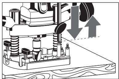
- Ocna6bTe 3aXMMHoi pbUar, onyCTnTe KapetKy Ha orpaHnHTeJIg Iy6uHbI n CHOba 3aTAYHHe 3aTJXHOI pbUar.
IobopoTHbI orpaHnUteIb Iy6HbI
Ppi 60bIuXr Iy6Hax fpe3epoBaHnI IN 60JIuXn DnAmTePax fpe3bl peKOMeHnyETcRfpe3epoBaTb B HECKOJIbKO IPOXoOB. Tpr Iy6HbI fpe3epoBaHnMOrYt 6bITb yCTaHOBJIeHbI Ppi NOMOIu BNHTOB Ha NOBOPOTHom ORpaHnHTeIe rIy6HnbI:
- UctaHOBtTe Tpe6yEmyIgIy6bHy fpe3epOBaHnKaK OINcAHO BblJe uYCTaHOBtTe ORpaHnHTeJIb Ha cMbI KOpOTKn BnHT (cMbI Hn3Kn yPOBeHb fpe3epOBaHn).
- YctaHOBInTe DBe NepBbIe Tny6HbI φpe3epoBaHnHa 6OJIee JINHHbIX BnHTax. CHOba 3aTaNITE BnHTbI n 3aKpeNITe OT nepeKaunBaHnI pI ni NOMOuN KOHTPOBOUHbIX rAek.
- Дяфpezeроваян, onуctиTe KapeTKy Do KacaHЯ O caMbIДлHHbI BnHT I 3akpenITE. ПоворачиВайTe orpaHUnTeJIb rJy6bHbI kaxdI pa3 nocJe Фpezeроваян.
UctaHOBka
CKOpOCTN
BpaUeHnA
(TOJIbKO y
MOJdJIeN
OFE 710).
Ta6nua 3JeKToHHbIX perynipOBOK
A = Hanmehbuee KojunyeCTBO 06oPoTOB
G = HanboJbuee KojunyeCTBO 06oPoTOB
B OTeJIbHbIX Clyuayx BO3MOxHbI 3peMeHHbIeIN3MeHeHnRCKOpOCTNBpaUeHnR Bpe3yJIbTaTEcuJIbHbIX BHeUHIX 3JIeKTPOMaHHTHBIX NOMEX.
| LU phacoh- ной phrebsы В мм | Materiel phacони фreьы | Мягков дерево | Древсан у-жени плітіы | Пл actи, пл ekсиглас |
| 4-16 | Бысторе-Жуця сты | F-G | - | D-E |
| 18-36 | E | - | C-D | |
| 4-20 | Товед-Сларовий | G | G | E-F |
| 22-36 | F | F | D-E |
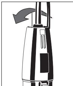
| Быклоуател "On-Off" ("Вkl./Вык"). | Выклоуене: ПerepondиHTь Быклоуател On/Off назад. Ддя ФбcaциНа Нжаь на поедию чась Быклоуател. | 1 2 |
| Быклоуенe: Hжаь на залию чаftь Выклоуател. Быклоуател abTomatuning Сперетсь В пооженe "0". | ||
| Установka пл actиково о З усторь (Bырл) (Hа ринад- л exхость*,КаT. HOMER: 4932 3117 22) | Вставыт пл actиково е зашию уст期权 STBO в осоване,кak поазано на уллuctраци. | |
| Установka гьбкоу валa (Dырл) (Hа ринад- л exхость*,КаT. HOMER: 4932 3300 00) | Остбte Затяжны виHT motopнo ч actи и Вьн'tе erOиЗ коруca. З akрение моторнию чаftь В дөрхате lnctурмени (КOD 3а��аа 4932 3192 27)и зakрение дөрхатel инстурение на верstake.Инстурени Можно тадже зakрениь с помошью стушь (КOD 3а��аа 4932 3018 06). З akрение Гький вал в сангre и ?атянite кренин giайу. | |
| Мakсимална скорость вразецень Инстурение 30 000 ob./Min.Позтум п olьзу teь только Гький вал с пдшинникам AEG (КOD 3а��аа сM. Выш). | ||
| Устристvo дя Корровань (Dырл) (Hа ринад- л exхostь*,КаT. HOMER: 4932 2499 77) | Ддя phezeровань по ошоблону (B),н оснobанe 德лжны 6ыть навичelinesн haiprabliaошпe(A). Ддя hapyxны контуров ошоблон (B)doJxen6bTY Mehblux pa3mepoB(C),ддя BнUTpehniux Контуров ошabLOн doJxen6bTY бolyше образывамо Детали. Ддягile habралюшe Btulkni C Вншим диametpom 25-40 MM можно ппоб畴tin кak Доюнitselьные akceccsyары. | |
| РUCСКИ | 71 | OF 500 S, OFE 710 |
| Пирспособ- ленидя фразецовань но крвов (Доролинов- ная рлиад- lexnoctb*, kat. HOMER: 4932 3132 74) | ОТBUHTITE наразавлиошие стетжни OT напrabлиошией peйки и п RimВИNTITE на празецовань ду phразецовань по крвов. | |
| Пирспособ- ленидя фразецовань но okрухносту (Доролинов- ная рлиад- lexnoctb*, kat. HOMER: 4932 2499 80) | Пробны вал в оdnу иЗ отberсту ду наразавлиошией peйки. Установite разиус мекдуcentrom и празильно фразец и заюп'te ВИNT. | |
| Адамер ду напrabлиош и. (Доролинов- ная рлиад- lexnoctb*, kat. HOMER: 4932 3618 66) | Одочтite napallentьню напrabлиошию OT наразавлиоший и заменite ee adanterpom. Посlete prizcisдионения adanterpa фразецовалыню машинку можно Веси вдoly наразавлиошиe (akcescuρ). 3To no3BOJET delaTb TOUCHOE Фразецованie. | |
| Экspл�атаць | Вedeite Истчимпговомпю образываем'deТали, deprжа erо obemnPykam. Всегда grabотайу невостру у наразаленью врашения Фразы (смогри有很大острацию), Иначe ВOSTMOXнA OTdau! Для точьх празых вбірозов посьзүүүүсь наразалюшey.800 mM Длино: No. 4932 3618 351400 mM Длино: No. 4932 3618 36 | |
| Посlete сны Корпуca фразецовальnam машина может Испolyзоватся кak празмь шлифовальnam машина. | ||
| РУССКИ | 72 | OF 500 S, OFE 710 |
| O6cIyXuBaanHe | BeHTnJIaZIOHbIe OTBepCTNЯ INHCTPymEHTa DoJIXHb I BceTgda 6bITb OTKpbITbIMI. ДЯТоTOчTObIg rapaHTnIPOBaTB ПОCTOJHHU OTOBHOCTb K paObTe INHCTPymEHT HeobXODIMO pIOBepaYb Ha IpredMeT N3HOCA yTOJbHbIX ΚETOK B OJHOM I3 cepBvCSbIX ΚeHTPOB Atlas Copco / AEG. ПОЛБaIteSb AkCESSCyapAMN I ZAPACHbIMI YacSTaMn TOLbKOФИРМы AEG.В Слуаe Bo3NHKnOBeHnI HeobXODIMOCTN B 3aMeNe, KOTOPaR He bbla OJIMcaHa, POnJALyIcTa, obpaauIteSb Ha OJINN I3 cepBvCSbIX ΚeHTPOB (Cm. CПСОК нашьx ragaHTnIHbIX/CeRbVCSbIX OprAHnIzaui). При HeobXODIMOCTN Moxet 6bITb 3aKa3aH ChpTeK XHCTPymEHTa C TrpExMepNbIM I3O6bApaeHnEM IeTalJeI. POnJALyIcTa, Yukaxite IeCЯТиЗнaHbI HOMep I TII INHCTPymEHTa I ZaKa9Ite ChpTeK Y BaJIX MeCTbIX aReHToB IINI HemocpeIcTeBENHO y Atlas Copco Electric Tools GmbH Postfach 320, D-71361 Winnenden, Germany. | |
| PyCCKn | 73 OF 500 S, OFE 710 | |
| 前言 | 如果您是高品味消費者,那麼AEG的產品,正符合您的要求。本公司研發的電動工具,不但使用壽命長,安全性也高。不過請您在使用前,務必仔細閱讀說明書,並照說明指示使用,如此才能發揮本公司產品之最大效益,並且避免不必要的職業傷害。希望您將從此成為AEG電動工具的最忠實顧客。 | |
| 規格 | OF 500 S OFE 710輸入功率 500 W 710 W無負載轉速 34000 min-1 30000 min-1最大無負載轉速 (針對無負載轉速極限功能失靈時)衝程 50 mm 50 mm 筒夾直徑 6 mm,8 mm,1/4" max.36 mm max.36 mm最大磨頭直徑在陶結合 20 mm 20 mm 在塑膠結合 38 mm 38 mm夾頸直徑 43 mm 43 mm重量 2,9 kg 2,9 kg配件不包括在內,請另外在配件目錄中選購。 | |
| 安全指示 | 請詳閱手冊上的安全指示!請務必使用機器的安全保護設備。操作電鑰時,一定要戴防護鏡。同時也最好戴上手套、防滑鞋及圍罩。機器在操作中,不可清除鐵削、木削。機設不可随意鑰孔,以防漏電。(最好使用自黏標簽)在更換任何機件前,請將插頭由插座拔出。確定開關已關閉,才可插上插頭。延長電線放在施工區之外。操作時,電線要置於機身後。只使用經過專業人員研磨之銖刀。注意!所使用工具的許可轉速,不可低於機器之最高轉速!進行铣磨以前,須將材料固定好。進行铣磨以後,將鋅磨機調回原來的位置(鬆開用來固定鋅籠的固定桿)。關閉電源開關之後,工具轉軸仍會旋轉。 | |
| 電源接頭 | ■材料的推進方向與铣刀的轉動方向相反(只能以逆轉向的方式作業)!為了安全起見,操作機器時請使用俱備防護功能之壓固裝置,檔板及助推器等輔助裝備。■使用圓周轉速45m/s的陶結合磨頭,或橡膠結合磨頭時,磨頭直徑不可超過20mm。使用圓周轉速80m/s的合成樹脂結合磨頭時,磨頭直徑不可超過38mm。■工作時所產生之塵埃多半有害健康(例如加工橡木,石材,已上漆材料等,都可能產生含鉛或者含著其它有毒元素之塵埃),最好勿讓此類毒塵侵入人體。工作時須使用吸塵裝置並配戴合格之防塵面罩。徹底清除積塵,例如以吸塵器吸除。 | |
| 用法 | 只能連接單相交流電,及說明書上所提供的電源接頭。本機器全是雙重絕緣(根據DIN 57 740/VDE 0740CEE 20),因此無須接地線,另外更符合歐洲標準EN 55014,對收音機及電視不會造成干擾。 | |
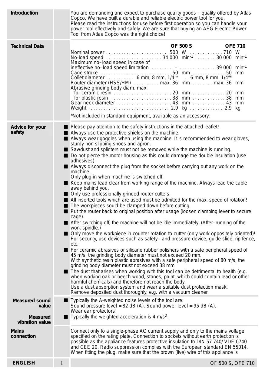
| 圖解 | 深度尺:可依照刻度,無段式調整銖深。 | |
| 電子調整轉輪:用來調整轉速。(只適用於 OFE 710) | 固定桿:用來固定銖籠。 | |
| 大而明顯的推式開關。 | 左輪深度尺:可預選三個銖深。 | |
| 固定引擎用的固定螺絲-鬆開螺絲後,可由銖籠取出引擎,並將引擎拿來做研磨機使用。 | ||
| 吸塵連結管:用來外接吸塵裝置。 | ||
| 堅硬的銖籠導引,可做無段式的銖籠高度調整;在鬆開固定桿後,銖籠會自動回到最高位置。 | 塑膠滑墊:保護易受損的材料表面。 | |
| 平行導引:做平行銖磨時使用。與材料外緣的距離可達240mm。 | 本說明書付印時,圖文均正確,但為配合不斷改進本公司產品,技術規格,如有更改,恕不另行通知。 | |
| 更換铣刀 | 在更換任何機件前,請將插頭由插座拔出。 | |
| 更換筒夾 | 筒夾直徑必須與铣刀柄的直徑相同。將铣刀柄盡可能地插入筒夾,然後以固定螺母來固定。卸下铣刀。將固定螺母轉鬆至可以取下铣刀為止。可安裝以下的筒夾:直径6mm,直徑8mm,直徑1/4"。(這些直徑數據,也是铣刀柄的直徑數據)1.將固定螺母連同筒夾完全轉出(也可參考"铣刀更換")。2.將筒夾由固定螺母抽出。3.將新的筒夾壓入固定螺母,且壓至可以感覺到已卡入為止。4.將固定螺母連同筒夾,旋緊在工作軸上。 | |
| 平行導引 | 1.如插圖所畫來安裝平行導引。2.將平行導引推入底板的孔中。調整好需要的距離,然後再以兩個蝴蝶形螺絲固定導引。要整齊,乾淨地鋅磨單面或雙面上膠板,請如插圖所畫來固定塑膠角尺。 | |
| 中文 | 76 | OF 500 S, OFE 710 |
EC-DECLARATION OF CONFORMITY
We declare under our sole responsibility that this product is in conformity with the following standards or standardized documents.
EN 50144, EN 55014-1, EN 55014-2, EN 60555, HD 400 in accordance with the regulations 98/37/EC, 73/23/EEC, 89/336/EEC
DEUTSCH
CE-KONFORMITETSERKL/ERING
D-71361 Winnenden Germany
http://www.atlascopco.de


Brand : AEG
Model : OF 500 S
Category : Drill