
BRIGGS & STRATTON 436777 - Gasoline engine BRIGGS & STRATTON - Free user manual and instructions
Find the device manual for free BRIGGS & STRATTON 436777 BRIGGS & STRATTON in PDF.
| Brand | BRIGGS & STRATTON |
| Model | 436777 (engine series 580000) |
| Product Type | Vanguard™ Gaseous Engine |
| Displacement | 953 cm³ (58.16 in³) |
| Engine Oil Capacity | 3.3 L (3.5 qt) |
| Fuel Type | LPG or natural gas (NG) |
| Cooling | Liquid (50/50 mix of phosphate-free antifreeze and tap water) |
| Starting | Electric (integrated starter) |
| Spark Plug Gap | 0.76 mm (0.030 in) |
| Spark Plug Torque | 20 Nm (180 lb·in) |
| Valve Clearance (Intake and Exhaust) | 0.18 mm (0.007 in) – cold engine |
| Air Filter (Ref.) | 820263 |
| Oil Filter (Ref.) | 491056 |
| Spark Plug (Ref.) | 496055 (resistive, with resistor) |
| Fan Belt (Ref.) | 821075 (940 mm) or 820893 (970 mm) |
| Oil Change Interval | Every 150 hours (or annually) |
| Maximum Operating Tilt Angle | 15° |
| Power Loss | 3.5% per 300 m altitude; 1% per 5.6 °C above 25 °C |
| Safety Accessories | Oil pressure sensor, automatic low-pressure shutdown, gas shut-off valve |
Frequently Asked Questions - BRIGGS & STRATTON 436777 BRIGGS & STRATTON
User questions about BRIGGS & STRATTON 436777 BRIGGS & STRATTON
0 question about this device. Answer the ones you know or ask your own.
Ask a new question about this device
Download the instructions for your Gasoline engine in PDF format for free! Find your manual BRIGGS & STRATTON 436777 - BRIGGS & STRATTON and take your electronic device back in hand. On this page are published all the documents necessary for the use of your device. BRIGGS & STRATTON 436777 by BRIGGS & STRATTON.
USER MANUAL BRIGGS & STRATTON 436777 BRIGGS & STRATTON
Briggs & Stratton is a registered trademark of Briggs & Stratton Corporation
© 2008 Briggs & Stratton Corporation, Milwaukee, WI, USA. All rights reserved.
Form No. 277109EST A
01999-87828

General Information
For replacement parts or technical assistance, record below the engine model, type, and code numbers along with the date of purchase. These numbers are located on your engine (see the Features and Controls page).
Date of purchase:
MM/DD/YYYY
Engine model:
Model:
Type:
Code:
Engine Power Rating Information
For 3/LC engines, gross power ratings are based on SAE J1995 criteria and net power ratings are based on SAE J1349 criteria. Actual power output of production engines installed in applications may vary depending on a number of factors, including the engine RPM limit of the application, environmental conditions, engine/equipment maintenance, and other variables.
Operator Safety
SAFETY AND CONTROL SYMBOLS

Fire

Moving Parts

Oil

Toxic Fumes

Slow

Fast

Stop

Explosion

Shock

Fuel

Choke

On Off

Fuel Shutoff

Kickback

Wear Eye Protection

Hazardous
Chemical

Read Manual

Hot Surface

Frostbite

Hot Liquid or
Steam
The safety alert symbol is used to identify safety information about hazards that can result in personal injury. A signal word (DANGER, WARNING, or CAUTION) is used with the alert symbol to indicate the likelihood and the potential severity of injury. In addition, a hazard symbol may be used to represent the type of hazard.

DANGER indicates a hazard which, if not avoided, will result in death or serious injury.

WARNING indicates a hazard which, if not avoided, could result in death or serious injury.

CAUTION indicates a hazard which, if not avoided, might result in minor or moderate injury.
CAUTION, when used without the alert symbol, indicates a situation that could result in damage to the product.

WARNING
The engine exhaust from this product contains chemicals known to the State of California to cause cancer, birth defects, or other reproductive harm.

WARNING
Briggs & Stratton does not approve or authorize the use of these engines on 3-wheel All Terrain Vehicles (ATVs), motor bikes, fun/recreational go-karts, aircraft products, or vehicles intended for use in competitive events. Use of these engines in such applications could result in property damage, serious injury (including paralysis), or even death.
CAUTION: This engine was shipped from Briggs & Stratton without oil. Before you start the engine, make sure you add oil according to the instructions in this manual. If you start the engine without oil, it will be damaged beyond repair and will not be covered under warranty.

WARNING
Gaseous vapors are extremely flammable and explosive.
Fire or explosion can cause severe burns or death.
When Adding Fuel
- Fill fuel tank outdoors or in well-ventilated area.
- Check fuel lines, tank, cap, and fittings frequently for cracks or leaks. Replace if necessary.
When Starting Engine
- Ensure that spark plug, muffler, and air cleaner (if equipped) are in place and secured.
- Do not crank engine with spark plug removed.
When Operating Equipment
- Never start or run the engine with the air cleaner assembly (if equipped) or the air filter (if equipped) removed.
When Transporting Equipment
- On Natural/Liquid Petroleum (LP) Gas engines, transport with fuel cylinder empty or valve closed, or fuel tank disconnected.
When Storing Equipment With Fuel In Tank
- Store away from furnaces, stoves, water heaters or other appliances that have a pilot light or other ignition source because they can ignite gaseous vapors.

WARNING

Starting engine creates sparking.
Sparking can ignite nearby flammable gases.
Explosion and fire could result.
If there is natural or LP gas leakage in area, do not start engine.
- Do not use pressurized starting fluids because vapors are flammable.

WARNING

Engines give off carbon monoxide, an odorless, colorless, poison gas. Breathing carbon monoxide can cause nausea, fainting or death.
- Start and run engine outdoors.
- Do not start or run engine in enclosed area, even if doors or windows are open.

WARNING

Rotating parts can contact or entangle hands, feet, hair, clothing, or accessories.
Traumatic amputation or severe laceration can result.
- Operate equipment with guards in place.
- Keep hands and feet away from rotating parts.
- Tie up long hair and remove jewelry.
- Do not wear loose-fitting clothing, dangling drawstrings or items that could become caught.

WARNING
Running engines produce heat. Engine parts, especially muffler, become extremely hot.
Severe thermal burns can occur on contact. Combustible debris, such as leaves, grass, brush, etc. can catch fire.
- Allow muffler, engine cylinder and fins to cool before touching.
- Remove accumulated debris from muffler area and cylinder area.
- Install and maintain in working order a spark arrester before using equipment on forest-covered, grass-covered, brush-covered unimproved land. The state of California requires this (Section 4442 of the California Public Resources Code). Other states may have similar laws. Federal laws apply on federal land.

WARNING

Severe thermal burns can occur by escaping steam or hot coolant.

- DO NOT remove radiator cap or reservoir cap if engine is warm or running.
- Stop engine and allow it to cool before removing radiator cap or reservoir cap and before changing or adding coolant.

WARNING
Unintentional sparking can result in fire or electric shock. Unintentional start-up can result in entanglement, traumatic amputation, or laceration.
Fire hazard

Before performing adjustments or repairs:
- Disconnect the spark plug wire and keep it away from the spark plug.
- Disconnect battery at negative terminal (only engines with electric start.)
Use only correct tools. - Do not tamper with governor spring, links or other parts to increase engine speed.
- Replacement parts must be the same and installed in the same position as the original parts.
- Do not strike the flywheel with a hammer or hard object because the flywheel may later shatter during operation.
When testing for spark:
Use approved spark plug tester.
- Do not check for spark with spark plug removed.

WARNING
Gaseous fuels are extremely flammable and readily form explosive air-vapor mixtures at ambient temperatures.
- Do not start the engine.
- Do not actuate any electrical switches.
- Do not use a phone in the vicinity.
Evacuate the area. - Contact the gas supplier or fire department.

WARNING

Wear eye protection when doing repair work. Frostbite can result from skin/eye contact with leaking LP liquid.

- Installation, adjustment and repair work should be done by a qualified technician.
- Regularly check flexible supply line. Make sure they are in good condition. Replace damaged or leaking components.

WARNING
Missing or inoperative "fuel lock-off" valve can cause a fire or explosion.
- Do not operate the equipment if the "fuel lock-off" valve is missing or inoperative.
Features and Controls
Compare the illustration 1 with your engine to familiarize yourself with the location of various features and controls.
A. Engine Identification Model Type Code
B. Spark Plug
C. Dipstick
D. Oil Fill
E. Oil Filter
F. Oil Drain Plug
G. Oil Pressure Sensor
H. Electric Starter
I. LPG/NG Mixer
J. Thermostat
K. Ignition Coil
L. Oil Pan
M. Alternator
N. Coolant Temperature Sending Unit
O. Engine Date Code
Operation
Oil capacity (see the Specifications section)
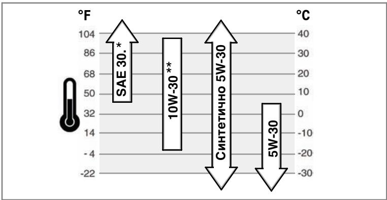
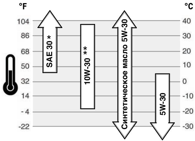
Oil Recommendations
We recommend the use of Briggs & Stratton Warranty Certified oils for best performance. Other high-quality detergent oils are acceptable if classified for service SF, SG, SH, SJ or higher. Do not use special additives.
Outdoor temperatures determine the proper oil viscosity for the engine. Use the chart to select the best viscosity for the outdoor temperature range expected.
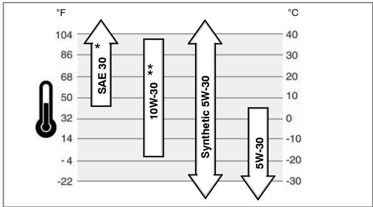
- Below 40^ F( 4^ C) the use of SAE 30 will result in hard starting.
** Above 80^ ( 27^ ) the use of 10W-30 may cause increased oil consumption. Check oil level more frequently.
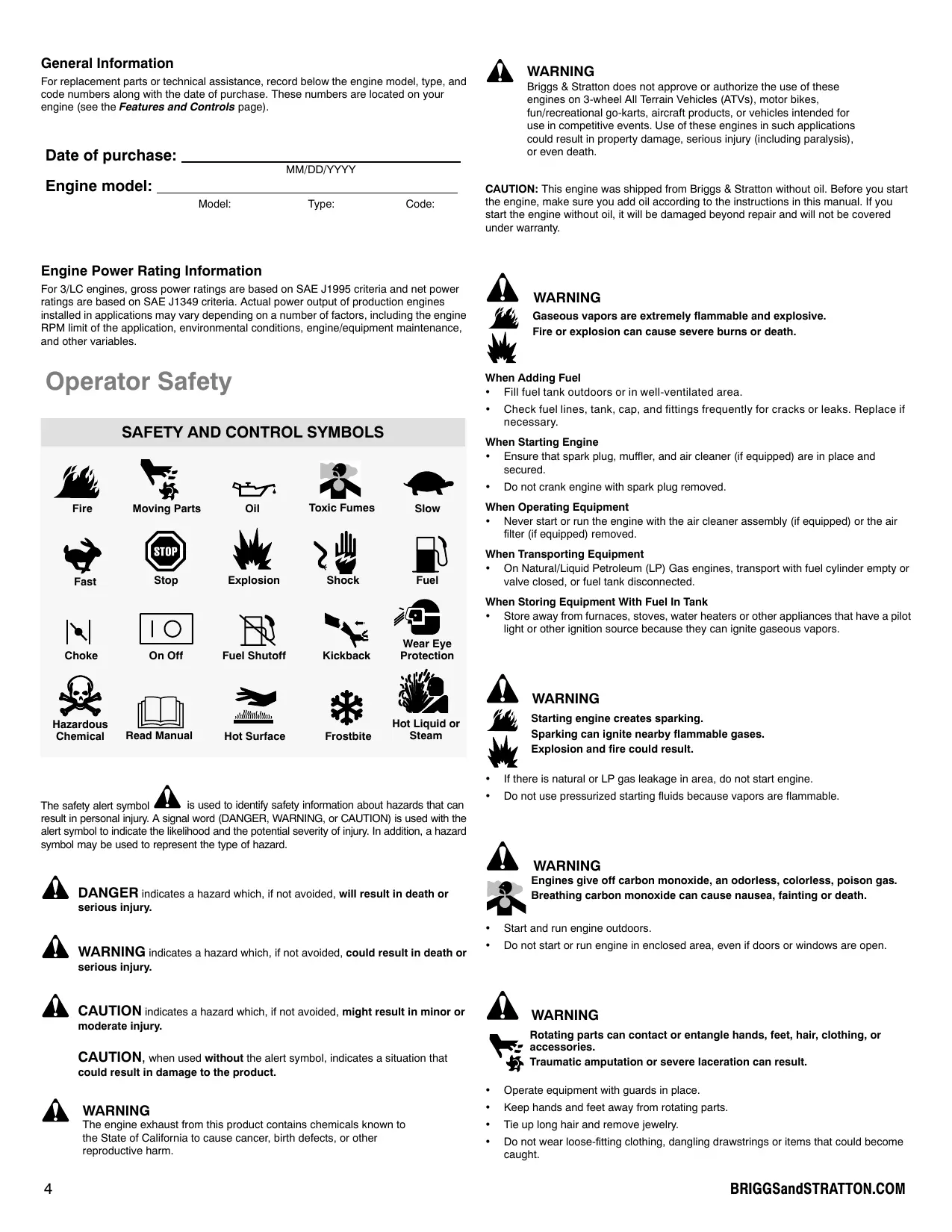
How To Check/Add Oil - Figure ② ③
Before adding or checking the oil
- Place engine level.
Clean the oil fill area of any debris. - Remove the dipstick (A) and wipe with a clean cloth (Figure 2).
- Completely insert the dipstick.
- Remove the dipstick and check the oil level. It should be at the FULL mark (B) on the dipstick.
- If low, remove the dipstick and add oil slowly into the engine oil fill (C). Do not overfill.
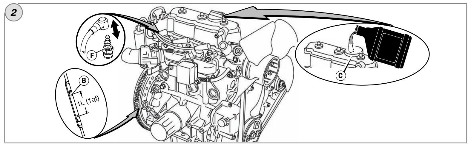
Important: When adding oil, adequate venting is required as follows:
- Remove the dipstick.
-
Make sure adequate clearance (D) is maintained between the oil fill device (E) and the engine oil fill (C). See Figure 3.
-
After adding oil, install the dipstick. Start and run engine at idle for five minutes. Shut off engine. Wait three minutes and check oil level. If required, add oil to bring oil level to the FULL mark (B) on the dipstick (Figure 2).
- Install the dipstick.
Oil Pressure
If the oil pressure is too low, a pressure switch (if equipped) will either stop the engine or activate a warning device on the equipment. If this occurs, stop the engine and check the oil level with the dipstick.
If the oil level is below the ADD mark, add oil until it reaches the FULL mark. Start the engine and check for proper pressure before continuing to operate.
If the oil level is between the ADD and FULL marks, do not start the engine. Contact any Briggs & Stratton 3/LC Authorized Dealer to have the oil pressure problem corrected.
Fuel Recommendations

WARNING
Missing or inoperative "fuel lock-off" valve can cause a fire or explosion.

- Do not operate the equipment if the "fuel lock-off" valve is missing or inoperative.
Fuel must meet these requirements:
- Use clean, dry fuel, free of moisture or any particulate material. Using fuels outside the following recommended values may cause performance problems.
- In engines set up to run on LPG, commercial grade HD5 LPG is recommended. Recommended fuel composition is fuel with a minimum fuel energy of 2500 BTU's/f ^3 with maximum propylene content of 5% and butane and heavier gas content of 2.5% and minimum propane content of 90% .
NG or LPG engines are certified to operate on natural or liquid propane gas. The emissions control system for this engine is EM (Engine Modifications).

WARNING: The equipment on which this engine is mounted is equipped with
an automatic safety gas "fuel lock-off" valve. Do not operate the equipment if the "fuel lock-off" valve is missing or inoperative.
How To Add Fuel

WARNING
Gaseous vapors are extremely flammable and explosive. Fire or explosion can cause severe burns or death.

When Adding Fuel
- Fill fuel tank outdoors or in well-ventilated area.
- Check fuel lines, tank, cap, and fittings frequently for cracks or leaks. Replace if necessary.
For information on refueling natural or LP gas engines, read the operating instructions supplied by the equipment manufacturer.
Coolant Recommendations
Coolant capacity (see the equipment manufacture's manual)
Important: This is a liquid-cooled engine. A 50 / 50% mixture of phosphate-free antifreeze and tap water is required for cooling, rust resistance, and lubrication of the water pump.
How To Check/Add Coolant

WARNING

Severe thermal burns can occur by escaping steam or hot coolant.

DO NOT remove radiator cap or reservoir cap if engine is warm or running.
- Stop engine and allow it to cool before removing radiator cap or reservoir cap and before changing or adding coolant.
Important: This is a liquid cooled engine. A 50/50% mixture of phosphate-free antifreeze and tap water is required for cooling, rust resistance and lubrication of the water pump.
- Before operating, check the coolant level. The coolant level must be between the FULL and the LOW/ADD marks on the coolant reservoir. If the coolant level is low, add a 50 / 50% coolant mixture of phosphate-free antifreeze and tap water to the reservoir.
-
To remove the reservoir cap after engine is cool, place a thick cloth over the reservoir cap. Slowly turn the reservoir cap counterclockwise to remove.
-
If the reservoir is dry, then add coolant to both the reservoir and to the radiator. See the equipment manual for location, operation, and maintenance of the coolant reservoir and the radiator.
- To remove the radiator cap after engine is cool, place a thick cloth over the radiator cap. Slowly turn the radiator cap counterclockwise to the first stop. If pressurized steam escapes from the cap, stand back to avoid injury. After all pressure is released, push down and turn the radiator cap counterclockwise to remove.
Gauges And Lights
The gauges and lights shown are typical and represent various options that can be used. See the equipment manual for location and operation of gauges and lights.

Coolant Temperature Gauge
Indicates coolant temperature when the electric start switch is in
the ON position.
Normal range 80^ - 90^ C (175^ - 195^ F
Dangerous range above 105^ (220°F)

Hour Meter Gauge
Indicates the total number of operating hours.

Fuel Gauge
Indicates the fuel remaining in the fuel tank. To minimize condensation, keep the fuel tank full.

Temperature Light
If the temperature light comes on, the engine is overheating. Stop the engine and check the coolant level (see the How To Check Coolant section). Check the radiator for debris that could restrict air flow.

Ignition Light
When the electric start switch is turned to the ON position, the ignition light should be on. When the engine is running, the
ignition light should go out. If the ignition light is out when then electric start switch in the ON position, check for a blown fuse.

Engine Oil Pressure Light
When the electric start switch is turned to the ON position, the engine oil pressure light should be on. When the engine is running, the engine oil
pressure light should go out. If the engine oil pressure light comes on when the
engine is running, immediately stop the engine. First, check the oil level (see the
How To Check/Add Oil section). Next, check the electrical system.

Charge Light
When the electric start switch is turned to the ON position, the charge
light should be on. When the engine is running, the charge light should go out. If the charge light comes on when the engine is running, check the electrical system.
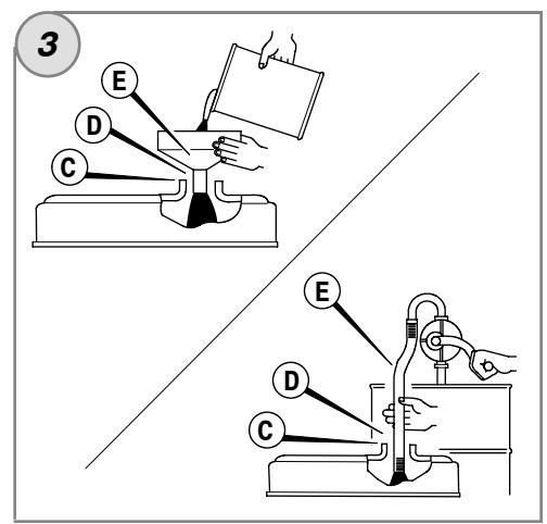
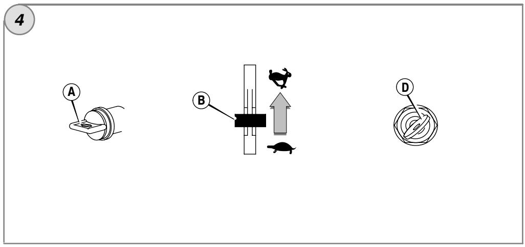
How To Start The Engine - Figure 4

WARNING
Gaseous vapors are extremely flammable and explosive.
Fire or explosion can cause severe burns or death.
When Starting Engine
- Ensure that spark plug, muffler, and air cleaner are in place and secured.
- Do not crank engine with spark plug removed.
- To prolong starter life, use short starting cycles, not to exceed 15 seconds per minute. Extended cranking can damage the starter motor.

WARNING

Engines give off carbon monoxide, an odorless, colorless, poison gas.
Breathing carbon monoxide can cause nausea, fainting or death.
- Start and run engine outdoors.
- Do not start or run engine in enclosed area, even if doors or windows are open.
CAUTION: This engine was shipped from Briggs & Stratton without oil. Before you start the engine, make sure you add oil according to the instructions in this manual. If you start the engine without oil, it will be damaged beyond repair and will not be covered under warranty.
Note: Some engines and equipment have remote controls. See the equipment manual for location and operation of remote controls.
- Check the oil level. See the How To Check/Add Oil section.
- Make sure equipment drive controls, if equipped, are disengaged.
- Turn the fuel shut-off valve (A), if equipped, to the on position (Figure 4).
- Move the throttle control (B) slightly past the slow position.
- Turn the electric start switch (D) to the on/start position (Figure 4).
CAUTION: To prolong starter life, use short starting cycles, not to exceed 15 seconds per minute. Extended cranking can damage the starter motor.
How To Stop The Engine - Figure

- Move the throttle control (B) to the slow position. Turn the key switch (D) to the off position (Figure 4). Remove the key and keep in a safe place out of the reach of children.
- After the engine stops, turn the fuel shut-off valve (A), if equipped, to the closed position.
Maintenance
Use only original equipment replacement parts. Other parts may not perform as well, may damage the unit, and may result in injury. In addition, use of other parts may void your warranty.
We recommend that you see any Briggs & Stratton 3/LC Authorized Dealer for all maintenance and service of the engine and engine parts.
CAUTION: All the components used to build this engine must remain in place for proper operation.
Emissions Control
Maintenance, replacement, or repair of the emissions control devices and systems may be performed by any non-road engine repair establishment or individual.
However, to obtain "no charge" emissions control service, the work must be performed by a factory authorized dealer. See the Emissions Warranty.

WARNING

Unintentional sparking can result in fire or electric shock.

Unintentional start-up can result in entanglement, traumatic amputation, or laceration.
Fire hazard
Before performing adjustments or repairs:
- Disconnect the spark plug wire and keep it away from the spark plug.
- Disconnect battery at negative terminal (only engines with electric start.)
Use only correct tools. - Do not tamper with governor spring, links or other parts to increase engine speed.
- Replacement parts must be the same and installed in the same position as the original parts.
- Do not strike the flywheel with a hammer or hard object because the flywheel may later shatter during operation.
When testing for spark:
Use approved spark plug tester.
- Do not check for spark with spark plug removed.
Every 8 Hours or Daily
Check engine oil level
- Check coolant level
First 50 Hours (initial Break-In)
Change engine oil *
Every 100 Hours
Check fan belt tension
Clean radiator
Clean air filter
- Check muffler and clean spark arrestor (if equipped)
Every 150 Hours
- Change engine oil *
- Replace oil filter
Every 600 Hours or Annually
- Replace air filter
- Check valve clearance
- Replace spark plugs
Annually
- Change engine oil *
- Replace oil filter
- Change coolant
- Check fan belt tension
Clean radiator - Check muffler and clean spark arrestor (if equipped)
- Replace air filter
- Replace spark plugs
-
Check valve clearance
-
Service more often when operating under heavy load or in high temperature.
Not required unless engine performance problems are noted.
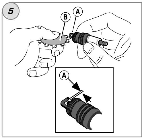
How To Replace The Spark Plug - Figure 5
Check the gap (A, Figure 5) with a wire gauge (B). If necessary, reset the gap. Install and tighten the spark plug to the recommended torque. For gap setting or torque, see the Specifications section.
Note: In some areas, local law requires using a resistor spark plug to suppress ignition signals. If this engine was originally equipped with a resistor spark plug, use the same type for replacement.
Inspect Muffler And Spark Arrester

WARNING
Running engines produce heat. Engine parts, especially muffler, become extremely hot.
Severe thermal burns can occur on contact.
Combustible debris, such as leaves, grass, brush, etc. can catch fire.
- Allow muffler, engine cylinder and fins to cool before touching.
- Remove accumulated debris from muffler area and cylinder area.
- Install and maintain in working order a spark arrester before using equipment on forest-covered, grass-covered, brush-covered unimproved land. The state of California requires this (Section 4442 of the California Public Resources Code). Other states may have similar laws. Federal laws apply on federal land.
Inspect the muffler for cracks, corrosion, or other damage. Remove the spark arrester, if equipped, and inspect for damage or carbon blockage. If replacement parts are required, make sure to use only original equipment replacement parts.

WARNING: Replacement parts must be the same and installed in the same
position as the original parts or fire could result.
How To Check Coolant
Important: This is a liquid cooled engine. A 50 / 50% coolant mixture of phosphate-free antifreeze and tap water is required for cooling, rust resistance, and lubrication of the water pump.

WARNING
Severe thermal burns can occur by escaping steam or hot coolant.

DO NOT remove radiator cap or reservoir cap if engine is warm or running.
- Stop engine and allow it to cool before removing radiator cap or reservoir cap and before changing or adding coolant.
Important: This is a liquid cooled engine. A 50 / 50% coolant mixture of phosphate-free antifreeze and tap water is required for cooling, rust resistance and lubrication of the water pump.
- Check the coolant level. The coolant level must be between the FULL and LOW, or ADD, marks on the coolant reservoir. If the coolant level is low, add a 50/50% coolant mixture of phosphate-free antifreeze and tap water to the reservoir.
- To remove the reservoir cap after engine is cool, place a thick cloth over the reservoir cap. Slowly turn the reservoir cap counterclockwise to remove.
- If the reservoir is dry, add coolant to both the reservoir and to the radiator. See the equipment manual for location, operation, and maintenance of the coolant reservoir and of the radiator.
- To remove the radiator cap after engine is cool, place a thick cloth over the radiator cap. Slowly turn the radiator cap counterclockwise to the first stop. If pressurized steam escapes from the cap, stand back to avoid injury. After all pressure is released, push down and turn the radiator cap counterclockwise to remove.
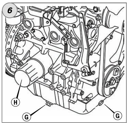
How To Change The Oil - Figure ② ⑥
CAUTION: Used oil is a hazardous waste product and must be disposed of properly. Do not discard with household waste. Check with your local authorities, service center, or dealer for safe disposal/recycling facilities.
Remove Oil
- With engine off but still warm, disconnect the spark plug wires (F, Figure 2) and keep them away from the spark plugs.
- Remove the oil drain plug (G, Figure 6). Drain the oil into an approved container.
- After the oil has drained, install and tighten the oil drain plug.
Change The Oil Filter
For replacement intervals, see the Maintenance chart.
- Drain the oil from the engine. See Remove Oil section.
- Remove the oil filter (H, Figure 6) and dispose of properly.
- Before you install the new oil filter, lightly lubricate the oil filter gasket with fresh, clean oil.
- Install the oil filter by hand until the gasket contacts the oil filter adapter, then tighten the oil filter 1/2 to 3/4 turns.
- Add oil. See Add Oil section.
Add Oil
- Place engine level.
Clean the oil fill area of any debris.
See the Specifications section for oil capacity. - Remove the dipstick (A, Figure 2).
- Pour the oil slowly into the engine oil fill (C). Do not overfill.
Important: When adding oil, adequate venting is required as follows:
- Remove the dipstick.
-
Make sure adequate clearance (D) is maintained between the oil fill device (E) and the engine oil fill (C). See Figure 3.
-
After adding oil, install the dipstick. Start and run engine at idle for five minutes. Check for leaks. Shut off engine. Wait three minutes and check oil level. If required, add oil to bring oil level to the FULL mark (B) on the dipstick (Figure 2).
- Install the dipstick.
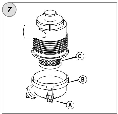
How To Service The Air Filter - Figure

WARNING
Gaseous vapors are extremely flammable and explosive.

Fire or explosion can cause severe burns or death.
- Never start or run the engine with the air cleaner assembly or the air filter removed. CAUTION: Do not use pressurized air or solvents to clean the filter. Pressurized air can damage the filter and solvents will dissolve the filter.
See the Maintenance Chart for service requirements.
- Open the latches (A) and remove the cover (B). See Figure 7.
- Remove the air filter (C).
- To loosen debris, gently tap the air filter on a hard surface. If the air filter is excessively dirty, replace with a new air filter.
- Install the air filter.
- Install the cover and close the latches.
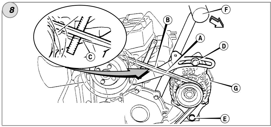
How To Check/Adjust The Fan Belt - Figure 8
Check Fan Belt
- Check the condition of the fan belt (A, Figure 8). If the fan belt has cracks or is damaged, replace with a new belt.
- Check the tension (B) of the fan belt. Press on the center (C) of the fan belt. If tension is correct, the belt will move 3/8 - 1/2 in (10 - 12mm) if 22 lbs (10kg) of force is applied to the center of the belt. If the tension is too loose, adjust as follows.
Adjust Fan Belt Tension
- Loosen the alternator mounting bolts (D) and (E). See Figure 8).
- Position a pry bar (F) against the alternator (G) and the side of the engine block. To tighten the fan belt, pull on the pry bar. Temporarily tighten the alternator mounting bolts.
- Check the tension of the fan belt. See Check Fan Belt section. If necessary, repeat the procedure.
- Tighten the alternator mounting bolts. Torque bolt (D) to 14 ft-lbs (19 Nm). Torque bolt (E) to 45 ft-lbs (61 Nm).
Storage

WARNING
Gaseous vapors are extremely flammable and explosive. Fire or explosion can cause severe burns or death.
When Storing Equipment With Fuel In Tank
- Store away from furnaces, stoves, water heaters or other appliances that have pilot lights or other ignition sources because they can ignite gaseous vapors.
Engine Oil
While the engine is still warm, change the engine oil.
Troubleshooting
Need Assistance? Go to BRIGGSandSTRATTON.COM or call 1-800-233-3723.
Specifications
| Engine Specifications | |
| Model | 580000 |
| Displacement | 58.16 ci (953 cc) |
| Bore | 2.835 in (72 mm) |
| Stroke | 3.071 in (78 mm) |
| Oil Capacity | 3,5 qt (3,3 L) |
Tune-up Specifications *
| Model | 580000 |
| Spark Plug Gap | 0.030 in (0.76 mm) |
| Spark Plug Torque | 180 lb-in (20 Nm) |
| Intake Valve Clearance▲ | 0.007 in (0.18 mm) |
| Exhaust Valve Clearance▲ | 0.007 in (0.18 mm) |
- Engine power will decrease 3.5% for each 1,000 feet (300 meters) above sea level and 1% for each 10^ F( 5.6^ C) above 77^ F( 25^ C) . The engine will operate satisfactorily at an angle up to 15^ . Refer to the equipment operator's manual for safe allowable operating limits on slopes.
Check when engine is cold.
Common Service Parts
| Service Part | Part Number |
| Air Filter | 820263 |
| Oil Filter | 491056 |
| Resistor Spark Plug | 496055, 5068 |
| Spark Plug Wrench | 19374 |
| Spark Tester | 19400 |
| V-Belt (940 mm) | 821075 |
| V-Belt (970 mm) | 820893 |
^+ We recommend that you see any Briggs & Stratton 3/LC Authorized Dealer for all maintenance and service of the engine and engine parts. Use only genuine Briggs & Stratton parts.
LIMITED WARRANTY
Briggs & Stratton Corporation will repair or replace, free of charge, any part(s) of the engine that is defective in material or workmanship or both. Transportation charges on product submitted for repair or replacement under this warranty must be borne by purchaser. This warranty is effective for and is subject to the time periods and conditions stated below. For warranty service, find the nearest Authorized Briggs & Stratton 3/LC Service Dealer in our dealer locator map at BRIGGSandSTRATTON.COM, or by calling 1-800-233-3723, or as listed in the 'Yellow Pages'.
There is no other expressed warranty. Implied warranties, including those of merchantability and fitness for a particular purpose, are limited to one year from purchase, or to the extent permitted by law and all implied warranties are excluded. Liability for incidental or consequential damages are excluded to the extent exclusion is permitted by law. Some states or countries do not allow limitations on how long an implied warranty lasts, and some states or countries do not allow the exclusion or limitation of incidental or consequential damages, so the above limitation and exclusion may not apply to you. This warranty gives you specific legal rights and you may also have other rights which vary from state to state and country to country.
OUR PRODUCT
Warranty Period
Consumer and Commercial Use
Vanguard™ 3/LC
2 years
Major Parts Warranty *
3 years
Parts & Labor *
2 years
- Note the following special warranty periods: For purposes of this warranty policy, Parts & Labor coverage is 2 years. Major parts only coverage is extended through the third year of operation. Major Parts Warranty (M.P.W.) covers but is not limited to or exclusive to cylinder block, cylinder head, crankshaft, camshaft, gears, pistons, rods, flywheel, flywheel housing, oil pump, fan, pulleys, mechanical governor, intake manifold, and oil pan. M.P.W. does not cover and is not limited to piston rings, replaceable bearings, water pump, any electrical component, valve train components, accessory parts, seals, gaskets, carburetors, exhaust manifold, hoses, all fuel system components, injectors, injector pump, turbocharger, muffler, any filters, radiator, thermostat, spark plugs, glow plugs, and fuel transfer pumps. The warranty period begins on the date of purchase by the first retail consumer or commercial end user and continues for the period of time stated in the table above.
No warranty registration is necessary to obtain warranty on Briggs & Stratton products. Save your proof of purchase receipt. If you do not provide proof of the initial purchase date at the time warranty service is requested, the manufacturing date of the product will be used to determine the warranty period.
About Your Warranty
Briggs & Stratton welcomes warranty repair and apologizes to you for being inconvenient. Any Authorized Briggs & Stratton 3/LC Service Dealer may perform warranty repairs. Most warranty repairs are handled routinely, but sometimes requests for warranty service may not be appropriate. For example, warranty would not apply if engine damage occurred because of misuse, lack of routine maintenance, shipping, handling, warehousing or improper installation. Similarly, warranty is void if the serial number of the engine has been removed or the engine has been altered or modified.
If a customer differs with the decision of the Service Dealer, an investigation will be made to determine whether the warranty applies. Ask the Service Dealer to submit all supporting facts to his Distributor or the Factory for review. If the Distributor or the Factory decides that the claim is justified, the customer will be fully reimbursed for those items that are defective. To avoid misunderstanding which might occur between the customer and the Dealer, listed below are some of the causes of engine failure that the warranty does not cover.
Normal wear: Engines, like all mechanical devices, need periodic parts service and replacement to perform well. Warranty will not cover repair when normal use has exhausted the life of a part or an engine. Warranty would not apply if engine damage occurred because of misuse, lack of routine maintenance, shipping, handling, warehousing or improper installation. Similarly, warranty is void if the serial number of the engine has been removed or the engine has been altered or modified.
Improper maintenance: The life of an engine depends upon the conditions under which it operates, and the care it receives. Some applications, such as tillers, pumps and rotary mowers, are very often used in dusty or dirty conditions, which can cause what appears to be premature wear. Such wear, when caused by dirt, dust, spark plug cleaning grit, or other abrasive material that has entered the engine because of improper maintenance, is not covered by warranty.
This warranty covers engine related defective material and/or workmanship only, and not replacement or refund of the equipment to which the engine may be mounted. Nor does the warranty extend to repairs required because of:
1 Engines that are not properly applied to equipment. It is strongly recommended that the factory be contacted prior to applying a B&S 3/LC engine to equipment that did not originally use a B&S 3/LC engine.
2 Problems caused by parts that are not original Briggs & Stratton parts.
3 Equipment controls or installations that prevent starting, cause unsatisfactory engine performance, or shorten engine life. (Contact equipment manufacturer.)
4 Leaking carburetors, clogged fuel pipes or injectors, sticking valves, contaminated injector pumps, or other damage, caused by using contaminated or stale fuel. Use clean, fresh fuel (lead free gasoline, diesel fuel) and Briggs & Stratton fuel stabilizer, Part No. 5041.
5 Parts which are scored or broken because an engine was operated with insufficient or contaminated lubricating oil, or an incorrect grade of lubricating oil (Check oil level daily or after every 8 hours of operation. Refill when necessary and change oil and oil filter at recommended intervals). OIL GARD may not shut down running engine. Engine damage may occur if oil level is not properly maintained. Read Operator's Manual.
6 Repair or adjustment of associated parts or assemblies such as clutches, transmissions, remote controls, etc., which are not manufactured by Briggs & Stratton.
7 Damage or wear to parts caused by dirt, which entered the engine because of improper air cleaner maintenance, re-assembly, or use of a non-original air cleaner element or cartridge. At recommended intervals, clean and/or replace the filter as stated in the Operator's Manual.
8 Parts damaged by over-speeding, or overheating caused by grass, debris, or dirt, which plugs, clogs radiator or air cooling access openings, or damage caused by operating the engine in a confined area without sufficient ventilation. Engine damage caused by not using accurate mix of anti-freeze and tap water, or water entering the engine due to any cause.
Engine or equipment parts broken by excessive vibration caused by a loose engine mounting, loose cutter blades, unbalanced blades or loose or unbalanced impellers, improper attachment of equipment to engine crankshaft, over-speeding or other abuse in operation.
10 Routine tune-up or adjustment of the engine.
Warranty service is available only through authorized service dealers by Briggs & Stratton Corporation. Locate your nearest Authorized Briggs & Stratton 3/LC Service Dealer in our dealer locator map on BRIGGSandSTRATTON.COM or by calling 1-800-233-3723, or as listed in the 'Yellow Pages™'.
Briggs & Stratton Corporation (B&S), the California Air Resources Board (CARB) and the United States Environmental Protection Agency (U.S. EPA) Emission Control System Warranty Statement (Owner's Warranty Rights and Obligations)
Emissions control warranty coverage is applicable to certified model year 2007 and later engines, which are purchased and used in California, and to certified model year 2007 and later engines, which are purchased and used elsewhere in the United States.
California and United States Emission Control Warranty Statement
The California Air Resources Board (CARB), U.S. EPA and B&S are pleased to explain the Emission Control System Warranty on your model year 2007 and later off-road spark-ignition engine over 19kW (25HP). In California, new off-road large spark-ignition engines must be designed, built and equipped to meet the State's stringent anti-smog standards. Elsewhere in the United States, new Non-road spark-ignition engines over 19kW certified for model year 2007 and later, must meet similar standards set forth by the U.S. EPA. B&S must warrant the emission control system on your engine for the period of time listed below, provided there has been no abuse, neglect or improper maintenance of your engine.
Your emission control system includes parts such as the carburetor or fuel injection system, the air cleaner, ignition system, muffler, and catalytic converter. Also included may be hoses, belts, connectors and other emission related assemblies.
Where a warrantable condition exists, B&S will repair your engine at no cost to you including diagnosis, parts and labor.
Briggs & Stratton Emission Control Warranty Coverage
The 2007 and later off-road spark-ignition engines are warranted for two years.
If any emission-related part on your engine is defective, the part will be repaired or replaced by B&S.
Owner's Warranty Responsibilities
As the engine owner, you are responsible for the performance of the required maintenance listed in your Operating & Maintenance Instructions. B&S recommends that you retain all your receipts covering maintenance on your engine, but B&S cannot deny warranty solely for the lack of receipts or for your failure to ensure the performance of all scheduled maintenance.
As the engine owner, you should however be aware that B&S may deny you warranty coverage if your engine or a part has failed due to abuse, neglect, improper maintenance or unapproved modifications. You are responsible for presenting your engine to an Authorized B&S Service Dealer as soon as a problem exists. The warranty repairs should be completed in a reasonable amount of time, not to exceed 30 days. If you have questions regarding your warranty rights and responsibilities, you should contact a B&S Service Representative at 1-800-233-3723.
EMISSION COMPLIANCE PERIOD: 1000 HOURS
Briggs & Stratton Corporation Emission Control Warranty Provisions
The following are specific provisions relative to your Emission Control Warranty Coverage. It is in addition to the B&S engine warranty for non-regulated engines found in the Operating & Maintenance Instructions.
1. Warranted Parts
Coverage under this warranty extends only to the parts listed below (the emission control systems parts) to the extent these parts were present on the engine purchased.
a. Fuel Metering System
- Carburetor and internal parts (if applicable)
Cold start enrichment system (if applicable) - Fuel injection system (if applicable)
Air/fuel ratio feedback control system (if applicable) - Fuel pump
Fuel filter
b. Air Induction System
Air cleaner
Intake manifold
Throttle body (if applicable)
c. Ignition System
Spark plug
- Ignition coil
- Ignition processor (if applicable)
d. Exhaust System
- Exhaust manifold (if applicable)
e. Catalyst System
- Catalytic converter (if applicable)
f. Miscellaneous Items Used in Above System
Pressure, temperature, position, speed sensitive devices
Electronic controls
- Connectors and assemblies
Hoses
- Length of Coverage
B&S warrants to the initial owner and each subsequent purchaser that the Warranted Parts shall be free from defects in materials and workmanship which caused the failure of the Warranted Parts for a period of two years from the date the engine is delivered to a retail purchaser.
- No Charge
Repair or replacement of any Warranted Part will be performed at no charge to the owner, including diagnostic labor which leads to the determination that a Warranted Part is defective, if the diagnostic work is performed at an Authorized B&S Service Dealer. For emission warranty service, contact your nearest Authorized B&S Service Dealer as listed in the "Yellow Pages" under "Engines, Gasoline," "Gasoline Engines" "Lawn Mowers," or similar category.
- Claims and Coverage Exclusions
Warranty claims shall be filed in accordance with the provisions of the B&S Engine Warranty Policy. Warranty coverage shall be excluded for failures of Warranted Parts which are not original B&S parts or because of abuse, neglect or improper maintenance as set forth in the B&S Engine Warranty Policy. B&S is not liable to cover failures of Warranted Parts caused by the use of add-on, non-original, or modified parts.
- Maintenance
Any Warranted Part which is not scheduled for replacement as required maintenance or which is scheduled only for regular inspection to the effect of "repair or replace as necessary" shall be warranted as to defects for the warranty period. Any Warranted Part which is scheduled for replacement as required maintenance shall be warranted as to defects only for the period of time up to the first scheduled replacement for that part. Any replacement part that is equivalent in performance and durability may be used in the performance of any maintenance or repairs. The owner is responsible for the performance of all required maintenance, as defined in the B&S Operating & Maintenance Instructions.
- Consequential Coverage
Coverage hereunder shall extend to the failure of any engine components caused by the failure of any Warranted Part still under warranty.
Osha mHΦopMaζη
3a pe3eBHN qACTn IIN TExHueCkA NOMOUI 3aIIuIeTe NO-DOy MOeNa, BuaN KOIOBeTe HA DInarTela C dAtaHa KynBuHaTe My. TeN KoIOBe Ce HAMnPaT BbPxy BaINH DInarTeR. (BIXTE cTpaHnUaTe EneMeHTu ynpaBHeN).
Data Ha KynyBaHe:
MM/DD/TTT
Moden Ha Dbratela:
MoeJ:
Tun:
KoIa:
HΦopMaζη 3a HOMHaJIHaT a MoIHOCT Ha DnBraTeJInTe
3aDbiratelenite 3/LC (Tpiu ninnnnpobn c BODHO oxnaqdahe) nbIHaTa MOUHOCCT ce OCHOBABA h KpItePnITe CbrIaCHO IpaBnHnka J1995 HA SAE (DpyxjcEbTO ha INHXeHPNErO t ABTomO6bnHata pommuJeHOCHT u TpaHCnopta), a POJNe3HATA MOUHOCCT -cBrracno KpItePnITe OT J1349 h SAE. POJNe3HATA npOn3B0dCTBEHa MOUHOCHT h DBrIaTeN, MoTHnPaHHa 3a pa3JInuHn npINIOXeHn, MOJE da Bapnpa B3aBnCmOCT OT rOIAM bpoi fakToPi, BkIIIOuHTeHNO rpaHnHNTe O6OpOTn Ha npINIOXHn MEXAHN3bM, YcONOBnTA h OKoHNHATA cpeDa, POnDPbXkKaTa H dBrIaTeN/obOpyDbaHETo n Dpyr nPOMeHnBn.
Texnka 3a 6e3oNaChOCT Ha onepaTopa
CIMBOJIN 3A BE3ONACHOCT IN YNPPABJIEHNE

Orheonacho

DbNxXeUc yeactn


OToPbHnTa3OBe

Бьрзобopotи

BabHN oboptn

Cron

B3pmboONtCHO

Onachoc3a npaxeHHN OT eNeKtpueckn TOK

TopuBO

Cmyka

Bkn. N3Kn.

IpekparBahe nOdaBaHTo Ha roPnBO

Obopaten yap

Ja ce hocat npedna3Hn Oylna

Onachn
xmmkakn

PpojeteTe PboKoBToDCTBO

Ropea noBbpxHOCT

OnachoctOT 3Mpb3BaHe

Iopeua TeuHocT nn napa
IpeDynpTeiHnHT CmBON 3a ONaCHOCT onpeDela IpeDoxpaHNTHa INfOpMaun 3a pNCKOBe, KOITo MOrAT da IOBeDat DO hapaHbAHe Ha nepcoHana. CnHAnuNpauza dma (OpACHO, PDEVIPPEXDEHENE uIN BHIMAHIE) ce nocTabe 3aeHNO C npEpynpTeiHc HCMBOJ, 3a da NOCUH BepoTHCtTa NOTeHuaHata cepMO3HOCT Ha HApaHbAHeTO. DOnblnHTeHIO, EInH CmBON 3a ONaCHOCT MoKeJa nOKa3Ba BVda HA ONaCHOCTTa.

ONACHO nocouba onachoct, korto, aKo He 6bIe n36erHaTa, ue doBepe do cmbpt uHcpeNo HapaHBAhe.

PNEyPEXKDEHNE noocya onaCHOCT, KOIto, aKO He 6bJe n36erHaT, MoKe Da doBee Do CmBPT NIn cepno3HO hapaHbAhe.

BHIMAHHE NOOCOVA ONaCHOCT, KOrTO, aKO He 6bJe n36eHATA, MoXe da DOBeDe Do MaNka UIN CpeHa CTenEH Ha HapaHBAhe.
BHIMAHNE, n3no3BaHO 6e3 npedynpeDnteHnN CMBON, noocBa CNyaua, KOTo 6n MoRJa Da doBede do nobpeXdahe Ha npodykta.

PNEyPPEKDEHNE
I3ropenite ra03e ot To3n dBiratel CbDbpxat XMMueeckn CbeDneHnna, nBecTHn ha ta Ta KaNidopnna Kato npnHnTeiHa pak, yBpexdAnn npn paXdahe, nn npdyn yBpeXdaHn, CbBp3aHn C penpoyKTHBHOCTT.

PNEyPPEXDEHNE
Kopnpaunn Briggs & Stratton He oobpna H ne no3bONBa n3no3BaHETO Ha Te3n DBIrAteJI BbPxy BCbExdoJI HA 3 KOJena, MOTOUKNETNI, YBEcENIeNTNHN/KOINuKN 3a KaTnIH, JetaTaN H anapATn INI TPAHCnOPTHn CpeCTBn 3a yHaCTNe B cCTe3aTeHN H mepoPnTn. I3no3BaHTo Ha Te3n DBIrAteJI H TAkINBA MaNNHO MOJE Da NOBeDe IO MaTePnaJIH N eTIn, CepNO3Hn HapaHABaHn (BKIOUHTeHNO npanaIIa) I dOpD NO CMbpt.
BHIMAHHE: HactoIaIIT DnIaTeIe CE DoCTaBb OT Briggs & Stratton 6e3 MacNo. IpeN da cTAPtIaPe TdINrAteIe CE yBepete, ye CTE HaneIe MaNo B Hero CnopeI nHCTpyKUInTe B TOBa PbKOBOCTBO. Ako ro cTAPtIaPe 6e3 MaCNo, Toi uca Ce NOpeRiD 6e3 Da 6bDe Bb3MOxHO Da CE pEmOHTnpa N rapaHcIraTa HMa da NOKpNbA betata.

PNEyPPEKDEHNE

BéH3INHOBITE Μ3napeHnRA Ca Μ3KJIIOUHTeJIHO Bb3ΠaMeHmM N B3PbBOONACHN.
Ioxkap nII B3pNB MOraT da npuHnT cepNo3nO obrapnna nn CMbpt.
Ppi DJIINBaHe Ha rOpNBo
- Пьнete pe3epboapa 3a ropuBO ha OTkpnto nIN B do6pe BeHTnnpaHO nOmeueHne.
- PpOBePbBaIte YeCTo rOpBONpOBoJnte, pe3epBoaApa, KaanayKaTa n cBeHHeHnra 3a pyKHaTnHn TeOBe. 3aMeHnTe rAn oKeHo6xOJIMO.
Pn cTaptnpahe Ha dBmraTeJIa
- YBepete ce, ye 3anaIITeHHaTa CBeu, uMOn3aIyUHTeN I Bb3dUHnA φnITbp (ako mTaKbB) ca Ha MRCTOTo cN i ca do6pe 3akpenen.
He pa3BbptaTe DnBraTeN C n3BaDeHa 3anaJIteHNa CBeU.
Ppi pa6oTea MaunHa
HnKoRa He StapTnpaIe N He pa6OTe C DnBnTaTeJI npi DeMOHTnpaH KOMnJIeKT Hb3duyHnIΦnITbP (aKO IMa TaKbB) INI cAMO Bb3duyWeH ΦnITbp (aKO IMa TAKbB).
PtpaHcnpoptnapeHaMaunHaTa
- DnrgatEnIte,pa6oTeuC BTEUHEN pnpOeH ra3/BTeUHEN npOaH-6ytAH (LP) da ce TpaHCnpOTnpaC nPpAeH cIIINHbP iIN 3aTbOpE H KpaH 3a rOpBTO, iIN C pa3KaH epe3epBoap.
Korato cknadnapate cbopbkeHHeTo C roPbBO B pe3epBoapa
CknAmpaTe Daney ot Neu,NeKn, BDOHOarpeBaTeNn IIN npyIn eNEKTPueeCKn np60pn, KOnTO IMAT CnHAnHaNamna INI pRy 3anaJNTeHEn m3TOHnK, 3auOTo TE MoRat Da Bz3PiMaHErT 6e3HINOBITE napr.

PPEyIPEXDEHNE

IyckaheTo Ha IbVraTeNa cB3daNcKpeHe.
UckpeheTo MOKe Da Bb3PnAmEH HAMpuaIte Ce HaOKOTo 3anaJIIMn ra3OBe.
ToBa moKe Da doBeDe Do ekCnIIO3n I IOXap.
- Ako Ima n3TnueHa He npuropoHe HJI BTeUHeH ra3 npOnaH B NOMeEHeNo, He cTApTuPaIte DBrAteJIa.
He n3no3BaIte ropnBa 3a NaalnHO 3aIaIbAHe NOd NaIraHe, 3aIoTO napTe mCa 3anaJIteJIHn.

PNEyPENKDEHNE

He pa6oTe c MaunHaT, aKO "n3KnIOUbaaIrT rOpIBOTO" Klanah IInCBA nHn He JeCTBa.
Elenentny uypablenia
CpaBHeTe NIOUcTaIaIraTc 1 C BaIaIaN DnBaIraTe, 3a da ce 3aNo3HaTe c pa3nOIOJKeHHeTo Ha pa3nIuHInTe EJIeMHTn ynpabNHeHn.
A. Mapknupobka Ha dBiratela Moen Tn Koid
B. 3anaJIteJIHa cBeU
C. HNBOJOKa3aTeI
D. OTBOP 3a HAIIBaHe Ha MacNo
E. MacienФиNTbp
F. Ipo6ka 3a n3TOUbaHe Ha macItoTO
G.ДатчИКЗаHAJIЯгHeHaMACJLOTO
H. EneKtpnueckn cTapTeP
I. LPG/NG Cmecntel (nponaHbTyah/npnpoDhen ra3)
J. Tepmoctat
K. 3anaHnTeJHa 606nHa
L. KapTeP 3a macNoTo
M. Antephatop
N.ДатчИКЗaTemпаратypаТа Ho oxlaЖdaшЯ areHT
0.Диагал Дата KoI
Pa60Ta
Bmectnmoct 3a maclo (hnpabete cnpabka b pa3deJ TexHnueckn daHHN)
Ppenopbkn 3a MacNoTo
3a nonyuabahe Ha hai-do6pn TeXnueckn Poka3aTei npenOpbVbame n3no3BaHTo Ha Macnata Ha Briggs & Stratton c rapaunn i ceptnpikat 3a kauceTbo. Dpyr BnCOKOKaeeCTBeHN MaCna C mneu npicaKn Ca npmeMnBn, ako Ca KlaacmnpuaHn 3a paobTHn peXmN SF, SG, SH, SJ nn No-BnCOkN. Da he ce n3non3bat cneuaHn do6abKn.
BbHnHNTe TEmnpaTpyn OnpeDenr npabINHH BnCKo3uTe HA MacNTO 3a DnRatEn. H3nON3BaIte Ta6muaTa, 3a Da n36epe Hau-Do6prr BnCKo3ntet 3a OyaKbHnDnAan3OH Ba HbNHHTe TEmnpaTpyn.
* Ako npn Temnepatypn no4 40^ (4^) ce n3no3ba macno SAE 30, toba ue doBede do Tpydno cTaptnpahe na dbratela.
** Пит emператун有很大 80°F (27°C) Изponьанeto на масно 10 W-30 може на пошнионсимашита на масно. Роберразиные по често НВОТо MY.
Kak ce npoBepBa/HaIbMa MacNo -FHypra 2 3
IpeuHaJIbAbe HJIN pOBeRbAbe Ha MacJIoTO
Pa3noJIOXeTe xOp3oHTaJIHO DnBraTeJIa.
- Почпстете мостOTO OKОLO OTBopa 3a Наловану На MacNo OT BCNUKN OTJOMKN.
1. CbaIeTe HbONoka3aTeJIa 3a MacIoTO (A) I rO n36bPweTe C uHCT PnAT (FInrpya 2).
2.ИЗЦАЛБМьКНЕТНВОПOKA3aTeЯЗа ropиВOTO.
3. Cbane HNBOKo3aTeI I npOBepe T HNBOTo Ha MaCnOTo. To Tp6Ba Da 6bJe do MapKnPOBkata FULL (B) Ha HNBOKo3aTeIa.
4. Ako e HnCKO, CBAneTe HNBONOKa3aTeJI N HaJIeTe BHNMaTeJIHO MaCIO npe3 OTBopa 3a IIbIHeNe Ha DnBaTeJIe (C). He ro npenbIbaIte.
Baxho:Korato HajiBaTe MaCNo, npaBnHOb BeHTnIpaHe ce n3nCKBa, KaKTo CneDbA:
CbaJeTe HbONOKa3aTeJIa 3a MacIto.
- Y6eTeCe, Ye NOIbIbPxkATE HxKyHOTO pa3CTOHNHe (D) MEXydy FyHnIa 3a NaIbMaHe Ha MaNLO (E) I CTeHATA Ho OTBopa 3a IIbJIHeHe Na DnIgATEJIA (C). BxKTe ΦNyrpa 3.
-
Cnéд наимbaheTo ha macnoto, noctabete HNBONOKaTeJI. CTaptnaIte n octabete DBNATeJI Da paobTu NET MmHTu Ha npa3EH XoJ. N3KJIIOUcTe DBnATeJI. N3kaKeTpe TpM mHyTu INPObepTe HNBOTo Ha macnTo. AKO ce HanaIra, haneIte Ose MaCNo, 3a Da DCtngHna HNBOTo My do MapKnipOBkata FULL. (B) Bbpxy HNBONOKaTeJI (ФИгур2).
-
NocTabete HNBONOKa3aTeJIHa MACJOTO.
HaJIraHe Ha macIoto
Ako HNBOTO Ha macNoTo E MHOrO HnCKo EeINd DaTtNk 3a HnIraHe (ako Ima TaKbB),
HInu Ns ce npe DnBnATEJI, HInu Ns ce 3aedcTbA anapMeHO t My yCTpOYCTBO. Ako ToBa Ce
ClyuH, CnPte TnDnBnATEJI n IpOBepTe HNBOTo Ha macNoTo C HNBOnOKa3aTEJI.
Ako HNBOTo Ha macNoTo e NOD mapKnOpBkata ADD, Doabete MacNo, Dokato
doCTrHne MapKnOpBkata FULL. CtaptnpaTe DnBnATeJI n IpOBepTe HaIraHeTo,
Ppei Da npOdbJxHte da pa6OTte.
Ako HNBO TAO HA MCNO T O MEX JIy MapKINPOBKMITE ADD U FULL HE CTAPnpaTe Dbratena.ObbPHeTe C kM HNKO yHbNHOMoUeHpeDCTABNTe Ha Briggs & Stratton 3a Dbrataten 3/LC,3a da OTCtPaNHe TpO6bMa HANraHETO HA MCNoT.
Ppenopbkn 3a ropmboto

PNEyPPEKDEHNE

JIINCBaU NII IN HeIeNCTBaU "I3KJIIOvBaU rOpNBOT" KJIaIaN MOKe da npuHnNoKap IIN EKCnIo3nA.

He pa6oTe c MaunHaT, aKo "N3KJIIOUBaIaIr TropIBOT" KJIaIaN IINCBa IIN He DeiCTBa.
Topnboto Tp6Ba Da OTROBAPa Ha cJeDnHe N3NCKBaHnA:
I3no13baIeYCHTO,CyIO rOpoB,6E3 BNrA HnHRAKcbB paxOB MaTePnAn.
I3no13BaHToHO HAropBA,INbH NpENOpBbAHHTe NO-dony Kateropm,MOke Da
doBeDo npO6bEmn BpaObTHata xapakTePcNtHa.
- Пи дигатели, ретуларида pa6o7OTc bTeчнe ra3 nponaH6ytaH, ce npenopbyaRa3 c TbproBCKOTO KaHECTBO HD5 LPG. ПрорьчанHT c6tabHa roPbOTo eTO3n, с MHNIMaIe ChEuФИeH TePMOdINAMUH eH NOTeHuaN IO 06eM, OT MHNIMYm (2500 BTU/foYta3) 93150 kJ/m³, c 5% MaKcIMaIHO cbIbpxaHne Ha npoiJIeH n 6yTaH, c 2,5% cbIbpxaHne Ha no-TeXKK rA3OBe n C 90% MINIMaIHO cbIbpxaHne Ha npoiAH.
DbIarateNTe C emnng Nnn LPG ca ceptniHpauHn da pa6oTATC npnpoeH ra3 nll BteueHn eRa 1pnan. Cnctemata 3a 606a C bpeDnTe EMcHn 3a To3n DbiratEn e EM (ModuNkauAn Ha DbratEneTne).

PNEpyPExKDeHHe:MaunHaTa,Ha KOrTo e MoHTpaH TaKbB
I3mepBaTeJIHn ypeDN u CBeTJIuHHN nHdNKaTOPN
Ioka3aHnte n3mepBaTeHNn ypeDNn CBeTNIHHN INHINKaTOpn ca TcAndapTHN n CbueCTByBat B pa3NIHn ONpN, KOtO MORaT da 6bDat HnON3BaHn. HanpaBete cnpBaKbA B PkoBOcTBOTO 3a pa6ota c 06OpyDbaHETO OTHOCHO pa3NOJIOXeHMeTO paboTaT aIM.

Tepmometbpa 3a OxnaKdaaata TeHOCt
IokaBa TemnepaTypata Ha oxnaDaaata TeHocT, KOrato
KoHTaKTHnT KJIoue Ha no3nua ON (BkJ.)
HopmaJIeH 0xbaT - 80^ - 90^ (175°-195°F)
OnaceH 06XbaT - HaD 105^ (220°F)

Yacobn6pory
OTUa cymapnB 6poi pa60THn YacOBe.

I3mepBaTeIeH ypeI 3a HAIuHOrTopBO
Poka3Ba ocTabeaToBpe3epBoapa rOpnBO.3a daHamaJIte KOHN3aunTaHa BOa, BInHarNoDlbpxaIte nbJeH pe3epBoap.

CBeTInHeH INDnKaTop 3a TempepaTypa
Ako CBETJINHHIAT NHIMKATOP 3a Temnepatypata CBETHE,3NAU, YDE BniratetaI e nperepI. Cnpete Dniratena I npoBepete HNBOI HOxNAkDaTaT aTeHOCB (BnxTe paoJeKak Ce npoBepBa
OxnaJaata TeHocT).IpoBepBaIte paIaNaTopa 3a HacNoBaHn, KOTo MoRat da OgrpauHt Bb3dUshnnotOK.

CBeTmHEn HmdkaTop 3a 3anaBaHe
Korato KOtakTHnT KIOUe ha no3uIN ON (BKn.), CBETJINHHIT INDkATOP 3a 3anaIbAne Tp6Ba da c
LOM DBIRATEENT 3apa6Otn, INHdkatopbT TpRbBa da nIraCHe. Ako INHdkatopbT He CBETn npri KOHTAKTeH KJIIOU Ha no3uN4 ON (BKn.)npOBeTe 3aMOrPnI ppeNa3ITen.

CBeTInHeH INDnKaTOP 3a HAnrAHe Ha MacJIoTO B DBrAteIa
Korato KOHTaKTTHIAT KJIIOUe Ha N03UNIaON (BKnL).CBETINHHNIT INHdkatop 3a HANrAHeTo Ha MaCNoTO TpA6Ba Da CBeTn. LcOM
ДИВIATEЛТ 3apabOTи, CBETINHNIHT INHДNKATOP 3a HAIJIraHETo HA MACNOTO TpRbBa DA 3a tarache. Ако CBETINHNIHT INHДNKATOP 3a HAIJIraHETo HA MACNOTO CBETn npri paOboTeu DBIrAteu, He3a6abHBO rO cnpete. ПьрBo npObepeTe HIBOTO Ha MACNOTO (HanpaBete cnpaBkA b p3aDien KaK ce npObepeBa/HaHbBa MacNo). CLeT TOBa npObepeTe eNeKTpnueckata cnCTema.

CBeTJnHEn HnDkATOp 3a 3apeKdaHe
Korato KOHTaKTTHIAT KJIIOUeHa N03UNIaON (BKnL).CBETINHHIaI INHdkatop 3a 3apExKaIe Tp6Ba Da CBeTn. LOM DnIRaTeJIaT
3apa60Tn, HNDAKATOpB Tp 13Rb6A da 13rAeCbe. AOK eCBTINHHNHT INHDAKATOp 3a 3apeXdHETO CEBTN pI np6oTeu DnIRatEn, npoBepeTe ENEKTPHECKATA CNCTEMA.
Kak ce cnapa Dnrgatele - Hrypa 4

PNEyPPEKDEHNE
BeH3INHOBITE N3napeHnra Ca N3KJIIOHTeJIHO Bb3PNaMeHmM IN B3PbBOONaCHN.
Itoxap nIb B3pNB MoRat Da npuHnT cepno3Hn 6rapnHn nn CmbpT.
PnCstapTnpaHe Ha DBrTaTeIa
- Y6eTeCe, Ye 3aapanTeHata CBeU, Wymo3arLyuWntTeJI N Bb3dyuHnA φnITbP ca Ha MCTOTO cn i Ca 3akpeneni.
He pa3BbptaIte DnBaTeTc N3BaTeHa 3anaJIteHa CBeU.
3a da npOdbIJIeTe KJbOTA Ha cTape, n3nOJI3BaJIeTe KpaTK cTapTOBn UIKIN, He no-DJIgN ot 15 ceK/MH. PpOdbIJIeTeHOTo pa3bPtaHe Moke da nobpeDi cTape.

PPEyPPEXDEHNE
Дигателп'te n3nyckat BbyrlepoDEH OKUC, KOITo e OTPOBEN ra3, 6e3 MIPNC u CBRT.
BdmbaHeTo Ha BbIpeOeH Okc MoKe da npuHH raDeHe, npnnaDbK nIn CmBpt.
- Cтартураиту paBOTeC ДВИгаTeЯ Habвн.
He cIapTnapeTe n He pa6oTeTe C Dniratela B 3aTbOpeHo NOMEueHne, OOpn n npn OTBOPeHn BpaTn nn np03Opu.
BHIMAHNE: HactoIaHT DBrAtateIe Ce DoCTaB OTr Briggs & Stratton 6e3 MacNo.
Ppei Da cTAPtIaTe DBrAtateIe Ce yBepete, ye Cte Hanei MaNo B Hero Cnpopei
HnCTpyKuInTE B TOBa PbKOBOCTBO.AKO rCtAPtIaTe 6e3 MaNo, ToJ ca Ce
IOBPeIe 6e3 Da 6bDe Bb3MOxHO Da CE pEmOHTpA n rapaHcNraTHa HMa da noKpNbA
ueTaTa.
3a6eJekka: HkOON DnBraTeNn N oOpuyBaHe ca Cha6dEnH c ycTpoiCTBa 3a dIuctanuMOHO npabneHne. HanpabeTe cnpaKBa B PbKOBoDCTBOTo 3a pa60Ta C oOpuyBaHeto 3a pa3nNoJxHHeTO n pa60TaTc ycTpoiCTBaTA 3a dIctaHUNHO ynpabneHne.
- Поберете НВОТа на macLOTO.НарравETe сравka в pa3deJa KaK ce npobepBa/HaHbMa MacNo.
- Ybepete ce, Ye 3aDbNkBaunTe ynpablenHa o6OpyDbaHTo, aKo nMa TaKnBa, ca u3KnIOueHn.
- 3abptete kpanheTo 3a noDabaHe Ha rOpBO (A), aKO mTaKOBa, Ha no3nui "on" (Furpa 4).
4.Ппемecтete locta ha pbuha ta ra3 (B) malko cnei no3nua tata slow - 3aBbptete KIOUa 3a eIeKtPmueckn CTapTep (D) Ha no3uun on/start (Hyrpa 4). BHMMAHNE: 3a Da npOdbJxNte XMBOTa Ha cTAPTepa, 3nON3BaHTe KpATKn cTAPTOBn UcKn, He No-dbIgnt O T 15 cek/MnH. PpOdbJxNteJIHTo pA3BbptaHe MOkE da NOBPedn cTApTepa.
Kak da cnpete DbIrataTeJ - Fnrupa 4
- IpeMeCTeTe pUHaTa ra3 (B) Ha no3mUnna 3a 6abHn o6oPOTn slow . 3aBbptete KIOHa (D) Ha no3nunoff (I3KKn.) (Φnrypa 4). CbaTe Te KIOUa n ro DpbXte Ha beOeONACHO MCTo, daJeT ou OCeBa H a Deua.
- CnEi cnIpaHHe Ha DBIrataTeHa, 3aBbptete KpaHcyTo 3a noDaBaHe Ha rOpnbTO (A), aKO mHa TAKObA, Ha 3aTbOpeHo nIoJKeHne.
Texnuecko obcnykbahe
3nON3BaTcMoCpOINHANHpe3epBHNt. Dpyr NaCTM Moze Da He cpa6oTAT Do6pe, Ma da NoBpeT DaBnAteT N da DOBeT DA HApAHBAHe. OCBen TOBA, INIOJON3BaHETO Ha Dpyr NaCTM Moze Da AnHynpa rapaHUNMTA Bn.
Hne Bn npopnbAme Na oocHTe HAKO T YbNHOOMOeHNTe npeCTABNTENHa Briggs & Stratton 3a BCyKn onepaunno TeXHueCKOTo n cepBn3HOTO 6cnyKbaHe Ha dBiratena/3/LC n peshepBNHTe cactn.
BHIMAHNE: BcunKn KOMNoHEnTn, n3IOn3BaHN npn pOn3BODCTBOTO Ha TO3n DInratae, Tpa6Ba da 6bDat ha MRCTOTo Cn 3a npabNHaTa My paOta.
KoHTpOJ Ha emncnnte
IopdpbKkata,cmHaata nnpeMOHTbT ha yctpoCTBaTa 3a KOHTPOHaBpeHNTE emCmN Moar da 6bdaT n3BbPwBAHn O TCEKn peMOHTe Hcexnn
TEXHK,peMOHTpAaDNrAte, KOnTo HE n3NO3BaT 3a TpaHCNOPTHcNI.
Bce naK,3a da noJyUHe "6e3nPaTHo" o6cnyXbaHe Ha yCTpoCTBaTa 3a KOHTPOHaBpeHNTE emCmN,pa6Otara Tp8Ba da 6bde n3bPwEha OTybnHOMOseH 3ABODCKnnpdctabnten.HanpaBeTe cnpaBka B rapaunraT aOTHOCHoBpeHNTE emCmN.

PPEyPPEXDEHNE
CnyauHIO NcKpeHe MoKe Da IOBeDe Do NOXkap IIN Nopa3BaHe OT eNeKtpnueckn TOK.
HeBONHO cTAPtnpaHc MoKe da IOBeDe Do 3axBaUaHe, TpaBMaTHHa amnytaunn nn do paHbAhe.
Onachoct OT noxkap
Ipei n3BbPwBaHe Ha peryInpOBKn nonpaBKn:
- Otkaute Ka6ena Ha 3anaJInteJHaTa CBeu n rO dpbXte daney OT HeA.
- O Tkauhe Te MInyc-KIemata Ha akymyIaTopa (cAmO npn DbrarTeN C eNeKtpueckn cTapTeP).
- I3noJ3BaIte cAmo IOxOJaI INHCTpyMeHTN.
He 3actonopraBaiTe c perynnapaata npyXnHa, IocToBInTe CnCTemn nIc npyn ChTn, 3a da nobunite o6oPOnTe Ha DnBnTaTeJI. - Pe3epBnHte qactn Tp86Ba da 6bDaT cbC sbIoTO kaueCTBO n da CE MOHTnpaT B CbUaT a N03uIa, KAKTO opunHaHnHte qactn.
- He ydprrte maxobnka c uyk nlin TBbpr nppeMeT, 3a0TO ToJ MOKe da ce cTPOsH no Bpeme Ha pa6ota.
PnH3npo6BaHe 3a nckpa:
- I3noI3BaIte Oo6peH TnT TeTeP 3a Cbeu.
He npabete npobepka 3a nckpa npn n3Ba.deHa 3anaIteJHa CBeU.
KaDa ce 6cnyXBa Bb3dyuHnHa nIITbp - Hnpya 7


PNEyPPEKDEHNE
Be3HIOBHTe 3napeHna ca 3KJIIOHTeJIHO Bb3JIaMeHIMM IN B3PBOOANCHI.
Iopkap nIIN B3pNB MOraT da npuHnHT cepno3Hn O6rapHHN nn Cmpt.
- HmKora He cstaptnaTe n He pa6oTe c Dniratena npn OTcpanen KOMPiKeT ha Bb3dyuHn4 pfJITbP.
BHIMAHHE: He n3non3BaIte CbCTeH b3dYx NnI pa3TbOpNTeN, 3a da noNCTBaTeФnITbpa. CbCTeHnIr T b3dYx MOKe da noBpeDi fNITbpa, a pa3TbOpNTe Iro pa3TBaprt.
OTHOCHO3NCKBaHnra 3a cepBn3Ho 06cnyXbaHe, HnpaBeTe cnpabKa B Kaprata 3a texHnueckoto 06cnyXbaHe.
- OTBOpTe cHKcatOpnte (A) n cBaJIte Te KanaKa (B). BnKTe ΦIrgypa 7.
- Cbane Te Bb3dUnHnA pntbp (C).
- 3a da OTCTpaHHTe HacNoBaHnra, BHHMaTeHNO No-ychKaIte Bb3duHnnaФиNTbpBbpy TBpda NOBbpxHOCT.AKo e npEkaJIeHO 3ambpcEN, CMeHETe ro C HOBФINTPb.
- MoHTnpaIte Bb3dyuHHnФnTTbp.
- NocTabete Kanaka n 3aTbOpete fukcatopnte.
Kak ce npobepa/b/peryulnpa peMbka Ha BeHTnlaTopa - Phrypa 8
ПоберразытepькаHa BeHTNJIaTopa
- PnOBepete cBcTOnHMeTO (A, FInypa 8). Ako npeMbka H a BENTHNaTOpa IMA NpKHTAHIN E NOPBDEHc, CMEHETO C HOB.
- Поберете onьbaheTo (B) habembka habeHTnataTo. HATNCHEte cpeData (C) habembka habeHTnataTo. Ako onlbabaTo e npabInHO, cpeData ha pembka ue ce npemecTe b c 3/8 - 1/2 nHa (10 - 12 mm) npn npinaraHe Ha 22 naHda (10 kg) cnla BbyxH He.Ako onlbabaTo e cna6o, perynipaTe ro KaKTo cneDBA.
PerylnpaHe Ha onbBaHeTo Ha pembKa Ha BeHTnlaTopa
- Pa3xJa6eTe MOHTaxKnHe 6oNToBe Ha aJItePHaTopa (D) u (E). BuxKe ΦnIpya 8).
- NocstabeTe MOHTaxHa aHaRa (F) Cpeu ay antepHata (G) n ctpaHaTa ha 6noka Ha dBnraTeHa.3a da oBtHeTe pEmbKa ha BcHTNaIopTa, n3terHeTe MOHTaxHaTa aHaHa.3aTetHeTe BpemHoMO HOTaxHIne 60NTObe Ha anTepHataOpTa.
- Поверете onьваhtо ha pemьka Ha BeHTnilatopa. HanpaBete cnpaBka B pa3dienповеркаHa pemьkaHa BeHTnilatopa.Akо с haJana, noBTOpeTe npOeDypata.
- 3aterHete MOHTAXHHTE 6oJIToBE H aIATEPHATOpA. 3aterHe 6oTtA (D) C bBPTaH Momet O T 14 naYnDpyTa (19 Nm). 3aterHete 6oTtA (E) C bBPTaH Momet O T 45 naYnDpyTa (61 Nm).
Cknaipahe

PNEyPPEKDEHNE
BeH3INHOBITE H3napeHnI Ca H3KJIIOHTeJIHO Bb3PImaHEHMN IN B3pNB0ONACHN.
Iopkap NnB3pmb Moat Da npuHnT cepno3n Obrapnna nN Cmpt.
Korato ckaiaipate cbojkeHneTo c ropno B pe3epBoapa
CknAinpaTte daJeT OT neu, neuK, BOHOHaRpeBaTeN nIn npytn EeKtpnueckn npioBOp, KOIO TmAT cngHAnHn lamnn nIn npytn 3aapanTeHN n3TOHmni, 3aOToT e MOrAT Da b3nIaNMeHT n3npaEHnTA tO 6b3HN.
MacnotoHaDnrgateTna
DOKATO DBNrAteT E BCE OUe TOnbI CMeHETe MacJOTO.
OTkpmbaHe n OTcpaHbAbe Ha Heu3npabHOCTn
Hyckdaete li ne ce ot nomo? Pocetete BRIGGSandSTRATTON.COM nni ce obaede Ta 1-800-233-3723.
TexHnueckn daHHN
CneuΦnkaun 3a DnurataJIa
| Моden | 580000 |
| РавOTEN obem | 58,16 in3 (953 cm3) |
| Въtrightchoose димамен на симлинданba | 2,835 in (72 mm) |
| РавOTEN xOD на буталOTO | 3,071 in (78 mm) |
| Вмостимост за масло | 3,5 qt (3,3 L) |
PerynpobbHn daHn*
3a JIINHIO TbproBcKO non3BaHe
Диогалов Vanguard™ 3/LC
2roDHH
TapaHcIa 3a OCHOBH Yactn\*
3roDnHn
Pe3epBnH qactn n BnlaHan Tpyd
2roDnHn
- Ot6beneke cneHnre cneunonn nepno: 3a ueHte Ha Ta3n rapaHOnHn noHnTnKa, nOKpnteTo 3a pe3epBnTe qactn n BnaRaHnT 3a zamHnata mtpd e 3a nepoD ot 2 roHH. Camo 3a ocHOBnTE p3eEBN HCTn rapaHIOHNO T oKpnte e pa3wnpHO n 3a tpetata p60Ha RoHHa. IapauHnra 3a ochOBnHe qactn (F.O.4) noKpmbA, HO He Ce ORpaHnuaE eINHCTBeH NO camo Do uinHnDPOBn6 bLOK, uinHnDPOBaT raNaBA, KOENHATn BA, p3aPpeJInTeHN HAN, 3bOHNt PpeabKn, 6yTAJIATA, MOTOBUNKNTe, MAXOBnKA, KOGXyA 3a MAXOBNA, MAcJeHATA NOMNA, BEHTINAtOPa, pEmuHNTe shuBn, MexauHnpyERyIaNTOcMekELN H KOLEKTNP and MocEnH N KAPET. F.O.4 He noKpmbA n He ce OrpaHnUba EINHCTBEHO n CAMO 3a 6yTAJIHnTE CERMeHTN, CmehenMeNTe NaRepn, BOHATA NOMNA, BCEKN eLEMENT OT eLEKTPueckata IHCTaIauZRA, 3aDbHXBaUnITE eLEMENTs 3a KNanAHNTe CNOMARATEENHNTe QACTY, YNPTbTHENHNTA, raphHTypNTe, KAp6bpatOpNTe, KOLEKTOPA 3a n3ROpEJIrTaBOID, BCNUKn eLEMENTn Ha rOpBnHA tCnCTema, PA3npbCKBaHNTe IIO3N, HarHeTaTeHNaTc NOMNA, Typ6okomnpecopa, yMUMzarglyuWtEner, BCNUKn qfNtprn, PAadnATOPa, TepMOCTATA, ZanlanlENTe CBEuN, HArpeBaTeHNTE CBEuN i NOMNTe 3a NoDABaHE na RopBOE, GapanuOHHNRT nepoND zanoovBa OT daTata Na KyuBaHeOT ppBnN Notpe6bntel HA dp6Ho INI ON KTkyuBaUca 3a TpRoBcK nI npDoBnKbA 3a nepoND O BPme, qKSCpAnB rOpHaT aTabNiua.
He e HeobxOIMa pernctpaunHa rapaHuaTa, 3a da ce nolnyr rapaHIOHO 6cIyKbaHe 3a npOyKTHe Ha Briggs & Stratton. Na3e 3a doka3aTeNCTBO KBITAHNTAOT NOKynkata.AKO He ocnrgpnte Doka3aTeNCTBO 3a HauHnHata data Ha KynBaHe, pni nonckBaHe Ha rapaHIOHO 6cIyKbaHe, datata Ha npOn3BOCTBO HA npOyKta ue 6bde n3no3BaHa 3a onpeJelne Ha rapaHIOHHn nepnoD.
OTHOCHOBaShaTa rapaHcna
Briggs & Stratton npnemat c roTOBHOCT rapaHUNOHN pEmOH n CE n3BnHBAT 3a npnHHeHTo BV HeYDo6CTBO. BceK N OToPnIHAP a cepBN3EH PneDCTABNTeHa Briggs & Stratton MOke DA oCbIeCTBn rapaHUNOHNTe pEmOHn Ha dBnATeNTe 3/LC.
PioubeTeO rapaHUNOHN pEmOHn Ce npoBExd patyINHO, HO NOHKAOra E b3MOXHO nCKaHnTA 3a rapaHUNOH CepBN3HO 06cJyXBae DA He ca ONpABDaHn. HanpIMep, rapaHnra HMa Da CE pIn3Hae, Ako NobpeDaTBA DnBnAteLNa Ce bJnxn Ha HENpABnHa yNoTpeBa, Na IINCA HA peDobHO TExNHcEcko 06cJyXBae, Ha HENpABnHO tpaHCnOpTNape, MaHEBpNAe n CKlaInpaHe nIi Ha HeKaYeCTBeH MoTHax. CbIo TaKa, rapaHUNaTcCe ryBn, Ako cepNnHT HOMep Ha DnBnATEe EOTCPaHeH nIi ca npaBeHN pOnMeHN IO CAMn DnBnATEJ.
Ako kynbvaht he e cbrnace h cpeweHneTo ha Cepbn3Hn npdctTabnten, ue ce hnapabn pnooyBahe, 3a da ce yctahOBn DaJIr rapAHnTae TpeN3HbI. NsckBaHTe OT Cepbn3Hn npdctTabNTB n peoCTABn 3a ppeoCTABn 3a ppeLEn BcNCHN DoNtBnTHe NPAKTHn HA cBOr DnCTPbYtOp INn Ha 3aOBA. Ako DnCTPbYtOpBt INn 3aOBDt peuH, ye TOBA nCKaHaE o npabDaHO, Kynbvaht tse bDe HapblHO o63uTeHn 3a DeFekTHnTE qactN. 3a da CE n36eTHe HeNoPa3yMeHNeTO, KOEt MOKe DA Bb3HNKHe MEXJy KynbvaH n PpeCTABTHeN, NO-DONy CA n36pOENH hKON O T pnuHInTe 3a nobPeDa B dBiratela, KONTO rapaunHnTa HE noKpMa.
HopmaHIO n3HocBaHe: DnBiratEnIte, KaKTO BCNUCKMEXAHUH NcTPOCTBa, cHyJzJaT OT nepMOiHa 3aMHa Na actu N o6CnykBaHe, 3a da paoTbT Dope. IpaHauNTA He NOKpNBA peMOHTA, KORATo npHOPMaHIO n3HOCBaHe dAdeHa cact NIM DnBiratEnT Ca n3ueHepnAn JxNBota Cn. IpaHauNTA He cPeNlNA, aKO B DnBiratEn CcLyu NoPBeda, nopAdn HnnpabuHNO nO13BaHe NmOTCbTBe Ha pyTHNa HnoDpBkKa, TPAHnOptnaHe, MAnHInynpaHe, CbXpaHnBaHe Nm HnepaBnEH MoTtck. CbIo taka, rapaHauNTA cRey, aKO cepinHnT Homep Ha DnBiratEn e OTCpaHEn Nm NO Hero Ca npabeHn PpOMeHN.
Henpabnno noodbpxhae: XIBOTb Na daaen DVBATeN 3aBNCN OT yCNOBnTA, npn KOnTO paobTn IN OT prnKtne, KOtO nOlyuBaH. KaON pnpIOeHNa, KaTO KUYNTBAtOpN, NOMIN, INOTAQUHNN KOCaYKN, MHORo CECTO CeI3NOJ3BAT B INpaUHa N 3aMbpceha CpeDa, KOEt MOxEJa Da NOBeE Do IpeDbaprTeHOTo IM N3HOCBAHe. TaKOBa I3HOcBAHe N Ce NKpNBa OT raPauHnTa, KORATo Ce IdbXKn HA MPbCOTn, npax, abpa3Nb 3a NoHCTBaHe Ha CbEuta NnDpyrN abpa3NbHN MaTePnAIn, nonaHaNb IN DVBATeN NOPaHn HEKaueCTBEHO nOdBpXHaE.
Ta3n rapaunna NOKPbBa cAmO yNtpe6eB V DBrataJIe DeEkeTeH MaTePnA n/nnn 13paBOTka, a He 3aMnHaTaN nn Bb3CTAOBRABAHETo Ha MaAnHATA, KbM KOrTO DnRaTeJIr MOKeJa 6bJde MoTNpAH. RapaunraTa He NOKPbNA n nonCKAHn peMOHTN npadi:
1 DnBraTeH, KOTo He ca npaBnHOMOTnpaHn KbM 3aDbNkBaHaTaMaHnHa. HAcToHnBO ce npenOpBvBa npdeBapntEHO da Ce o6bPheT KbM 3aBoDa, KoraToe MOnTpAte 3-UNINIOB DBnRatC BOHO OXnJaXdE B&S 3/LC KbMaHnHa, KoTO He n3No3Ba, No hauano, DnBraTeI B&S 3/LC.
2 Поблеми, пишины OT части, кою не са оригинални части на Briggs & Stratton.
3 YcTpoiCTBa 3a ynpabIeHne Ha MaIINHATA nI IN CbOpJxehnI, KOITo npeHT ha CTApTnPAHeTO HA DmRATEN, BOJIT NO He3AIOBONITENHATA My paObTA IIN cKbCBATX JNBOBTa. (KOHCyTIpaIte Ce nPON3BOITENHa YcTPOiCTBATA.)
4 Kap6byapotn c TeObe, 3aIpbctEn npOBOni nIn pa3npckBaun iOn3n 3a roPBOTO, 3aJIENHJIAN KJanaHAn, 3aMbpceHN HArHeTATEHNI NOMN ININ dpyra NOpeJa, pInuHEneHa OT aMbpceHO IN INpTeoIO rOpBNO. YInOpTe6BaHte YIncTo, pIncHO rOpBNO (bEHNH bE3 cbIbpXaHne Ha ONoBO, nIn3eNoBO rOpBNO) n CTabUns3atop Ha rOpBNO Briggs & Stratton c KaTanoKeH No 5041
5 7actn, KOIO TO CA HApaHn IIN ChyHEn, 3aOTo DBrAteTJeT e pa60tnc HeoctatbHIO INI 3AmBpCeHO MaCNO, INI C MaNc O HenoDxHAnQ KaeeTO (PpOeRbAHTe EexdHeBHO HNBTO HMaCNo TIO N CneD BCEKIN 8caSa p60ta. Korato E Heo6XoDMO, DOJIbAte N CmEHNTE MacNTo N MaCnEHNZ fInTbp Ha npenOpbYBaHNT INTePBANOT BpeMe). AByapinHO yCTPOJCTBO OIL GARD MOKe Da He cPipe p6oTeuNDA BrAteTEN. AKO HNBTO YCaMnTo Hce neoDbpxka ToHNO, DBrAteTNe MOne Da ce NobpeDN. PpOeTeT PeKOBODCTBO T3 a6pOta.
6 PemOH NTn pereynpnahe Ha MOHTnpaHn qactn nIIN arperatu KaTO c6dHHTeHN, npedabateHN MExaHm3Mn, dNCTaHUNoHn ynpabJeHn I dp., KOtO He ca npom3BeHn oT Briggs & Stratton.
7 NOBpeHa IINI IN3HOCBaHe Ha Yactn, npuHHeHn OT HeNCTOTn, nOaHnA h B DInrAteJIa, nopA INe HKeAeCTBeHO NOdBpXaHe HA Bb3DyUHnA FJITbp, HEKaueCTBeH NOtOpEn MOHTa INI ONI3NoI3BaHe Ha NEOpHNaHn EJeMeHn 3a FJNTpa. Ha npenOpBvAHnTe INHTepBaNl OT BpMe NoIcTBaTe W/INi CmEHaBaiTe FmTTpa, KaKTo e nocOeHo B PbKOBOcTBoTO 3a pa60Ta.
8 TaHn, NOBpeHn nopAaH naBnueHm MaKcImaJIHn OobOpTu nn nnpaI npepRbAe, bJbKaAaO ce Ha TpeBn, HAcNoBaHn mN 3AmbpcBaHe, KOnTO 3Anyubat, 3aDpbCTBaP aHaNtOpa IIN OTbOPTe 3a DoCTbN ha OxnaJdAua Bb3dyx, INI NOBpeA, bJbKaAaCe Ha pa6oTa B 3aTbOpEno pOocTpcaHTo C HeNOcTaTbHa BEHTNaua. NopeHa Na DbrVaTeRn, dJbJkaAa Ce Ha Hecnla3BaHeto HA ToHOTc BOtHOuWHe A aHtnFpNi 3 nITneHa BOda nn Ha npOHKKBaHTo HE BAoDa B Hero No HRAKBA pMnuHa.
9 9actn ha DbrarateIy mMaunHata,CyynenHOTpekomepHa B6paIaIy, DbljkaaCe Hxla6abMOnTak HxDraTeIaY, Xna6abN peXeUH OHOBe, Xna6abN pIaCTnHm Hxla6abN IIN3JeBaIaNcHpaH paOToH KONeIa, Ha Heo6pO KynPiapHe MaNaHInH KbM KONeHATnBan Ha DbrarTeIa, Ha CBpbXbCOKnO6opOt nIy dpyra 3noynOpTe6pa npiaPobota.
10 PyTHINHa HAcTpoIka Ha epYIIpOBKa Ha DBIgATeJIa.
TapaHauOHHO cepBn3HO 6cClyXBaHe e DoCTbIHO eHNCTBeHO Ype3 OToPnIpaHTe cepBn3Hn npEcdTabIeN Ha KopnpaIaBrIGgs & Stratton. HamePeTe Ha-6bn3Kn OToPnIpaH cepBn3EH npEcdTabIeN 3a DBIgATeJIte 3/LC B haata yKaaTeJIHa Kapta 3a npEcdTabIeNte Ha aDpec BRIGGSandSTRATTON.COM, mII KaTO ce o6aIte Ha TeI. 1-800-233-3723, nII KaKTo e nocOeHb J,KbIITne CTpaHIuM"
Vseobecné informace
Pries jjungiant varikli

HaedeBaIte 3aunthbIe OOK

OnaChbIe XmMueeCKne BWeECTBa

UHTaIe
pykoBODC

TopaHnOBepxHOCTb

06mopoxeHne

Topyaar
JNDKoctb
nnpap
IpeDynpTeBbH3nAICNObIb3yeTcRdIgOB03aHeHnHOpMaunO6 OAnChbIX CITyaUaHXKOTOpBE MOrY TpNbBeCTN K TpaMe.C 3TNIM 3HaKOM NcNOb3yeTcR CnHaNbHoe CNoBO (OINACHO, OTOPOXHO IN BHIMAHNE), yKa3bIbAOoee Ha BepoTHoCTbN TONeHApIaBHyIO TRaeCtB TpaBM. B DOnOpHeHme, CmBoJOn aChOCTM MoKET NcNObIb3ObTaCBdIg YKa3aHnBnDA OnaCHOeN.

ONACHO yKa3bIbaeT ha ONaCHyIO CNTyaUIO, KOTOPa#, ECNI ee He n36eKaTb, npBBeTeK cMeptelHOMu NcXoHy nn cepbe3HO TpaBMe.

PNEyPEXKHeHNe yKa3bIaET Ha OnaChyIO CnTuayIO, KOtOpAra, ecNn ee He N36eKATb, MoKet PnBecTn K CMeptelbHomy NcXOy MIn cepBe3HO TpaBme.

BHIMAHHE yKa3bIbaeT ha OnaChyU cNtYaauIO, KOTOPaE cSIn ee He n36eXaTb, MoKET npNBcTeN K TpaBMe cpeHNe TAnKeCTn NnN JERKO TpaBMe.
BHIMAHNE, KOrda nCnOJb3yETc6e3 npEduPpeIuTeNbHOro 3HaKa, yKa3bIbAet Ha CNTyaCuHIO, KOtOpA MOxET npUBeCTN K nobpeXDeHIO u3denn.

OCTOPOXKHO
BbIXONHbIe Ra3bI bIbratEna CoepKxAT XMMUeCKne IpOyKtBi, KOTOpBle, NO daHHbIM uTaT a KaMfOpHnA, Bb3BaIaOT paK, depeKtBi y HOBOpOJdeHHbIX uINu HIIte HapuyHenH penPOdyKNBHO fYHKUN.

OCTOPOXHO
KomraHnBrigs & Stratton He Oo6pIeT Hne pa3pe7aet IcNoIb3ObaHne dAnHHbX DVBtAEteHa TPEKoJIeCHbIX Be3dExOxoAAX, MOTOUKNJax, pOryOIOHbIX/pa3BLeNBeKbIbIX KAPTHRAX, B03dyuHbIX CyDHX INI aBTOMoBnIaX, npeIHa3NaueHbIX dNIA cNcNoIb3ObaHnB CopeBHOBaHnx. VcNoIb3OBAHne Hauix DVBtAEten B DaHHbIX CEJAX MOKeT npVbECTN K nopHe IMyueCTBa, Cepbe3hIM TpaBMam (BKIOUaY naPapAH) INI daXe K CmeptelbHomy NCxOyD.
BHIMAHNE:Данньдвгагелпocstabлгетскомпанne� Briggs & Stratton 6e3 macna.перед зучcodм двогатя,обзатelно залешte macno cornaCHO nHCTpykциЯн HabToIgero rykoBoOdCTBa.EcIn Bby 3aynctnte Двогатяь 6e3 macna, TO dbraratelb 6ydet HOBOCtahOBmIO nobpexdeH, n 3TOT cnuyaH he 6ydet nOKpbibatcbra rapaHTnei.

OCTOPOXKHO
Ta3006pa3HbIe NcnapeHnRABJIOTcRtopIOHMN B3PbIBOONaChbIM. BocpIaMeHeHne IINB3PbIB MOrYT npNBecT N CInlbHbIM OXKOrAM IIN cMeptelbHomY nCXoY.
Pn do6abJeHm TOnJIbBa
3aONHnIte TOnJIINBbIb 6aOK, IIn6o Ha OTKpbITOM Bo3dyXe, IIn6o B xopoio npOBetpmbaem0 30He.
PerynpoBepaTe TOnIINBOIpOBoD,6ak, npO6ky uΦHTnHn Ha HAnuTpeunH yTeueK. Pn Heo6xoDMocTn, 3aMeHnTe Detan.
Pn3znyckeDburatela
- Y6eHITcB,уTO CBea 3axnraHn, rIyunTeN b BO3dyuHbIФnIbTp (ecn yCTaHOBnE) HxOJATCnHa CBOUX MeCTax n HaeXHo 3akpeHneHbI.
He npOBepaTe NcKpy C BbHyToI CBeuey 3axuHaHn.
Ppi 3Kcnpnyataunn o6OpydoBaHna
- HmKoJa He 3aynckaIte N He 3KnpyuTte DnBtateNb 6e3 yCTaHOBNEHORO y3na Bo3yXooHCTntErl (ecnn yctaHOBNe) n nn BO3yUHOrO funltpa (ecnn yCTaHOBNe).
Ptp TpaHcnpTnpOBKe o6OpydoBaHn
PekomehdaqunnoNCNoB3OBaHHIO MacJa
Mby peKOMeHdyem IcNoJIb3ObaTb pa3peWHeHbIe KOMmaHne Briggs & Stratton MacnaIdIaIOCTNKeHn HauLyuHnx 3KnIpyataUOnHbIX xapakTePncTik. DpyrIe BbICOKoKaYeCTBeHbIe DeTePeHTbIe MaCna DoNyCKaIoTcB Tom Cnyae, ecNI OHN KlaccnФu\PobaHbI Ka"For Service SF, SG, SH, SJ" nII bByue. 3anpeuaTcHcNcOJIb3OBAHne cNeUaJIbHbIX do6aBok.
Temnepatypa IApuyxHoro 03Dxya ONpeJeAET HaINeJxauyIO Br3KoCTb MOTOPHO Mmacna. BocnoJIb3yTeCb TabIeM dN bIbOpa COOTBETCYUoi EBR3KoCTn dN OXuJaEMOrIO HInTePbana TEMnpatpybl HApuyxHoro 03Dxya.
- IcnoIb3OBAHne Macna SAE 30 npn TempepaTpax Hxke 40^ (4^) npuBeTeK 3aTpduHHeHOMy 3aNyScy DInrataTeI.
** IcnoIb3ObaHne Macna 10W-30 npn TempepaTpyax Bblue 80^ (27^) npBBeTe K noBbIeHNOMy nOtepeJIeHIO Macna. Yaune npOBeRnTe yPObEhMacna.
Kak npoBepuNb ypoBeH MaCJa/DoJntb MacNo -Pnc. ② ③
Ipeed do6abHeHnem nI npOBepKoYpOBHa macna
YctaHOBIne DbIratel B Ropn3OHTaIbHoe NIOJoxHeHne.
OChCTIte 30Hy maclo3aJIbHOrO OTBepCTnO TIO6o Mycopa.
1. Bbytaunte uyn nla n3mepeheny ypoBna Macna (A) n o6oTpne ero YnctOri TpnoKoi (Pnc. 2).
2. Понноctью BCTabte уун дул Измерену урови macna.
3.ИЗБЕКТЕУПИ NGOBЕРTEуровь Macla.OHdoJIKeH6bITbHaOTMeTKeFULL (3aONHeHO)(B)Uya.
4. EcnI yOBeHb HNKe, N3BJIeKInTE uyn n MeJdJeHNo 3aJIbAte MacNoYepe3 MacNoHaJIbHyIO rOpNOBHy (C). He nepenOnnTe. BHMaHHe: PnI dONiBKe macNa Heo6xOJIMo ObecneHt b HaJnxKaUyIO BEHTINIAuIO CNeJdyUoiMn O6pa3OM:
- N3BJIeKInTe Uyn.
-
Y6eIITecb B HauNmHIOCTaTOHOrO 3a3OpA (D) MEXky UcTpoIcTBOM 3aINBkMacna (E) N 3aINBHOrTopoBHOJ DnIRaTeJIa (C). Cm. PncyHOK 3.
-
Nocne doJINBkMaCna yCTAHOBnTE uyn. 3aBeDnTe DnBraTeNb n daNe emy nopabotatb nTb mnHyt ha xOJOctbIX o6OpOtax. BbIKIOHTe DnBraTeNb.
IpoJxNITe TprMnHytBn InpoBepbTe yPoBeHb Macna. Ppi HneO6xoDmocTn, DoneJeMacNo Do OTMeKn FULL (3aOpJHeNo) (B) Ha 7yne (Pnc.2).
- YctaHOBInTe ⅢyI.
DABJIEHNE MACJIA
EcnI dabnHne MACna CNIuKOM Hn3KOE, pene daBnEHn (ecnn IMeTc) octaHOBNT DbratEn Ii6o BKNIOHT CNHbOe yctpoCTBO Ha oObyOboAH. B 30m cnyae OCTaHOBITE DbratEn Ib npOBepBe typOBeHb Macna npn NMOOni uyna.
Ecnn ypOBeHb macna HnXe OTMeTkn ADD, 06abBte Macno do OTMeTkn FULL. 3aNyCTte DnIraTeB n npOBeBte daJIeHne macna, npKJe che m npOdoJnatb pa60ty.
EcNn ypoBHeMa naxoAnTc MxNy OTMeKamAdd N FULL, He 3aanyckaTe Dbratetb. Obpatntecb KIObOMO oIbMOHOBMy dInepy kOMNaHm Briggs & Stratton 3/LC dlnyycTpeHneHcnpAHOCTN, Bbl3BaBwH Nn3Koe DaBnHne MaCna.
PeKOMeHdaunn no nCNoJb3OBaHnIO TOJIINBa

OCTOPOXKHO
OTcyTCTbUoIuIuIuIe Ha pa6OtaUoiu 3aOpHbKJIaHaN NoaTuONJIMBA MOXET CTaTB pUHHOIOXkapa UIN B3pbIbA.

3anpeetaetc 3KcIpyaTupOBaTB o6OpyOBoHne npn OTCyTCTByUoem nIn He pa60taoouem 3anopHOM KJIanahe noaun ToPnINBa.
TOnJIbO DoJxHc COOTBcTcBOBaT b CnEduoum Tpe6oBaHm:
IcnoB3yIe YCxOE TOINMBE, He COpeRjAaee BlaHn IIN KAKIX-NIO6 HNOPOBHyX cTtN. IcNoB3OBAHne TOINBIA, HE COOTBETCTByIOyo Yka3aHHbIM PEKOMENDAQAMM, MOKET PnIBeCTN KIOpOBJEMAM BO BPEMA 3KcPNIyATAuMI.
- EcnI DnBnIaTeNb IpeDHa3HauCh ENIpa60TbI Ha CxNIXeHNOM ra3e, peKoMeHdyETcNcOJIb3ObaTb Ra3 MapKn HD5. PeKoMeHduYEmb CoCTAB TOnIIBa DOnJKeH IMetb MmHMnblHyTO TeNlOTy CROPAnH B 2500 6pnTaHcKnx TEINIOBbX eDNIuC/foYr3 CMAkCMaJIbHbIM COdePckAHmE IpOnPiNeHa 5% i C codePckAHmE 6byTaH a 6Olee TRKeJeBix Ra30B 2,5% i C MnHMnblBbHbIM cOedePckAHmE IpOnaHa 90%.
Дигател ha npirodHom (NG) nI IN CxNKeHHom HeФтнHom ra3e (LPG) cepTNpUPOBaHbI nIЯ paObI ha npiroDHom nIN JxNkOM npONaHE. CnCTema KOHTPOnJ 3MnCCn IIN daHnHO DnRatela - 3TO CnCTema EM (MOndKauCIn DnRatela).

PNEyynPEXDEHNE:ObopyoBaHne,HaKOTOpOMyCTaHabnBaeTc
daHHbI DnBraTeNb, 6OpdyoBaHO npEdoXpaHHTeNbHbIM 3aOpHbIM KlaHaOM
npekpaueHnnoaunra3a.3anpeaaetcnaKcnnyatnpoBaTbO6opydobaHne npn OTCyTCTBHyUeEMnnn Hepa60taUoem 3anopHom KJanahe noaunra3a.
Kakdo6abntb tonnbo

OCTOPOXKHO

Ta3006pa3HbIe Icnapenra ABJIOTcR rOpUHMN IN B3pbIBOONaChbIMN.
Pn do6abJeHm TOnJIbBa
3aONHnIte TOININBbIb 6aOK, IIOHO HA OTKpbITOM BO3dyXe, IIOBO XopoIo npOBetpBaem0 30He.
- PerynapHO npOBepRte TOnnBONpOBoD,6ak, npO6ky nФHTnHn Ha HAnuHne TpeunH yTeueK. Pn Heo6xOIMOCtN, 3aMeHnTe Detan.
IINHFOOPMAUNIO 3aNPABKE Dnuratenei,pa6OtaOuIMN HA npnpoDHom IIN CxKJENHOM rA3e,BNHMATeBNO pOChTuTe INCTpyKUnn N3TOTOBITeJI O6OpYdOBAHNI.
PeKOMeHdaunn no nCnoJb3ObaHnO oxJaXdaUoee XnDKocTn
Obem oxlaqdaioe xnkoctn (cm.pykoBOcTBO n3rOToBnTeIa 60poydoBaHn)
BnHmHaNe:3To DnBraTeNb XnKoCTHOrO OxJaDeHn.ДЯ OXJaDeHn, npeODTbPaUeHnOBpa3OBAHnR pXaBUnHbI cMzKn BOdHOrO Haccca Tpe6yetcNcNoJIb3OBAHn50/50% Cmecn aHTncPpH3a, He coepxauero focpaTa, N BODOnPOBDoHn BObl.
PpOBepka/DoJIbBka OXJaXDaIOUeJ XnIkoCTN

OCTOPOXHO

3To MoKet npBecTn K cepbe3HbIM TeNIOBbIM OXOKaR M pe3yIbTaTe Bb6poca napa nnrnpaey OxnaKaJIoUe KKnKOCTn DnuratEn.

HE chImaIte KpbIuKy paIaNatOpa uNn EMcKoCTn, ecN nDbIrTaTeNb rOpyuN npa60taet.
- Pered CHrTneM KpbIuK paIaIATOp IA NkPbIuK paCuaPiTeBnHOrO 6aKa I nepe3 zameHoi IIN DOJIaMbKOI OXlaJDaIOUe JxNkoCTN OCTAHOBITe DBIrTaTeB I daJIte EmY OCTItB.
BnHmAHne: 3TO DnBraTeIb JxNkOcTHOrO OxJaXdEHn. IJr OXJaXdEHn, npEoTbPaUeHN o6pa3ObAHn PxAVBuHbI cMzKn BOdHORo Haccca Tpe6yETcNcNoJIb3OHaBn 50/50% CMeCN aHTnFpN3a, He coJePxaUe foocpata, N BoDOnpBOdHOB OBoIb.
- Пелед Эксплуатугей поверьт eуровь exларош eи kнoctn.YpoBE h oxлждош eи kнoctndoJoxeHb6tBmexdYOTMeTKAMNFULLILOW/ADDha EMKCTNoxaxJaOoEeKnKCTN.EcynpoBoH eoxlaaoe JxuKoctn H3K3n,doJeTe B EMKCTS50/50% CmEc boxlaaoe JxuKctn COCTOse n3 aHTnppn3a,he Coepkaetaofoocpata,N BOONPOBOHOB OBObl.
2.ДЯСТЯКрБИКУ EMKOCTN NOCE OXNAJDEHNY DBURAteN NOLOXITE TONCTYOKaHB Ha KpbIbUc YEMKOCTN.ДЯСТЯМEDENHNO NOBOPaUNBaTe KpbIbUc pOITMIB HACOBO CTPEKN. - Ecni emKocTb COBepseHNO nctaI, OdobbTe OXnaJdaIOUyIO XnDKoCTb EMKoCTb N b paDiNATOp.CM.pyKOBoCTBO NO o6OpYdoBaHNO dIg MecTOPOXKeH,N 3cKnIpyatauIN N o6CnyJnxBaHNI EMKOCTN OxJaXdaIOe XnDKOCTNo paDiNATopA.
4.ДЯСНТЯКршкп радиаторя посе oxnaждени Двгateля полжnte TOTCYTO TkaHb Na Кршky радиаторя.Мдненno nobopaunBaite Кршky радиаторя потовчасов CTpeJKNdo nepBoro OOrpanuHHTeN.Есн n3-iod Kршк BbIXOJNT nap NOД давлenerm OToJnTe,уTOБи N36ExaTb TpaMbI.Пocne TOrOK AO BCE DAblJeHMe 6yJet c6poSoHe HaxMmeKршky радиаторя BHN3и NOBERHnTE eue npotNV hacOBor CTpeJKe dЯ ChTЯ.
Pn6opbI nHnDKaTopbI
Ioka3aHHbIe np6opby INHdkaTOpby ABHJOTc TINHbIMN I NOka3bIBaHTO pa3HnHbIe BapnaHTbI, KOTOpbe MOrY INCNoB3OBaTbCra.ДЯ INHcpOpMaun O pacnoLoxEHm I yHKpIax np6obpoB INHdkaTOpob 6paTNTecb K pyKoBOdCTBY NO 3KcNlpyataun.

Pn6op TempepatypbOxlaJkaIOuee KNDKoCTN
Ioka3b1aBET temnepatypy oxnaJdaHoue JxNkOCTn, KORda BIKNoHTeJIb 3JeKTPoCnTcMb 3anycka yCTAHOBnB H NOXoHEB KJI.
HopmaJIbHbI dIaIa3OH 80^ - 90^ C (175^ - 195^ F)
OnachbI dIana3oN BbiE 105°C (220°F)

Pp6op KOJIueCTBa Yacob pa6oTbI
Ioka3bIbaET cymmaphoe KOJInueCTBO yacOB 3KcIpyatauIN.

Yka3aTeIb TOnJIHbA
Ioka3bBaet KOJIueCTBO TOJINBA B TOJINBHom 6aKe.ДЯ CHIXeHnA KOHNcHauN DEpXInTe TOJINBHbI 6aK 3aONJIHeHbIM.

INHdkatop TemnepaTpybl
CBeueHHe INMnKAtOpa TEmnpaTpyb CBNTeTbeCTByET O npeperBeB dInrataTeIy. BkIIOHTe DnrtatEn b npOBeTpE yOpeBEN oxnaXauOeJxNkOcKnTc (Secm. pa3dEn PpOBePKoOxApaOoo
KnKocnt).Y6eIITecb B OTCyTCTBm Mycopa Ha paImaTope, npenrTCTByuOero NOTOKy BO3dyxa.

HdkaTop 3xKunraHn
Pn yctaHObKe bblKIOUaTeIaJIeKTPuYeCKoRTO 3aNyCkaB nOLOXHeHc BKL INDnKaTOp 3axIrAHaM DOnJKe HCBtntbCBA.
PnpaBoTe DnBraTeNl HmDkATOp 3axmraHnHe NOJxhen CBeTntbC.
Ecn npy cYtaHOBKe BbIKIOuTeA 3JeKtpnueckOro 3anyka B
nonOxHne BKNI HmDkATOp HE CBeTntc, npObeTpne pRedoxpAHnteB.

HdNKaTOp DaBHeHMaCJa DBrTaTeIa
Pn yctaHOBKe BbIKIOuTeJI 3IeKtpUeCKOrO 3aNYcKa B NOLOXeHne BKINHIMKATOp DaBHeNMaCna B DInrAtene DoJXe CBeTntbCra.
Pn paobote Dbrateta INHdkaTOp daBHeHH MaCna B Dbratane He donKeH CBeHTbCBA. Ecn npn paobote Dbrateta NaH aayan CBETNbCBn HdnKaTOp daBHeHH MaCna, HemeJneHBO BkIIOHTe Dbrateta. B nepByo OpepeB npOBepBte ypoBHeMaCna (m. pa3den KaK npOBepBb/DonNbaTb MacNo). 3aTeM npOBepBte 3JIeKTPnueeCKyO cnCTemy.

HdNkaTOp 3apAdkn
Pn yctaHOBKe bIKIOUaTeJI 3JEKTPuYeCKoRo 3aNyCa B NOLOXeHne BKJ INHINKATOp 3apAKn DOnJKe H CBeITbCJI. Pn pa6Ote DInrataTena
INHdkatop 3apJdkn He doJXeH CBetntbC. EcIn INHdkatop 3apJdkn HauHaet CBetntcb npi pa6ote DbrarTeJI, npOBepte 3neKtpueckyo CNTemy.
Kak 3anycntb DvraTeIb - Pnc. 4

OCTOPOXKHO
Ta3006pa3HbIe NcnapeHnRABJIOTcRtopIOHMN B3pbIBOONaChbIMBocPnAmHeHne NmB3pbIB MOrYT npNBecT N CnJbHbIM OXKOrAM NmCmeptelbHomY nCXoY.
Pn3zanycke DmraTeJia
- Y6eIITcB, yTO CBea 3axnraHnA, rnyuNTeB n BO3dyuHbI pMlbTp yCTaHOJIeHbI n HADEXKHO 3aKpeJIeHbI.
He npobepaTe nckpy C BbHyToI Cbeeu3axnraHna.
-Дя у breastассракonsьстарета,норьштей корOTКЕстapTOBIE цилны,пrelьвшалочи� 15 сухид в муну. Пюдлжгельни зуck может сироггг�тч МOTOPстарета.

OCTOPOXHO
BbIOnHbIe ra3bI cOepKaT Okncb yrIepoA - 6ecuBeTHbI n He HMeUoi 3anaXa JDoBtbl ra3.
BbIXaHne OKncy yrIepoJa (yraphoro ra3a) MoXeT Bbl3BaTb pBOTy, notepu co3HaHn IIN cMeptb.
3anyckaIte n 3KcPnyaTpyuTe DBrTaTeB BHe NOMEueHna.
He 3anyckaite DnirateIb NomeeHn IaKe np OTkpbItbIX Okhax IDbepx.
BHIMAHHE:ДанньдИгATEЛБ NOCTABJIETC KOMПанe Briggs & Stratton 6e3 macna.петед зуckOM DBIgATEJI,ОБЗATeLbHO 3aJIeTte MacLo cOrnaCHO nHTpyKUЯM HACTOJEU pykoBODCTBA.EcIn Bb 3aNCTte DBIgATEJIb 6e3 macna, TO DBIgATEJIb 6yDET HeBOcctAHOBUMIO NOBpexdE,и 3TO TcIyai He 6yDet nOKpbIbA TbCB rapaHtne.
Приемаиме: HeKOTOpbIe DBnraTeN I O6OpyDoBaHne Cha6KeHbI opraHamM AnDCTaunOnHOO ynpabJIeHnA. KacateIbHO paCNoJooHeHnI np6OtBt OprAhOB DuctaunOnHOO YnpabJIeHnCMOTpIte pyKOBoDcTBO NkCnPyTaUmI dNf KOHKPETHOrO 6OpyDoBaHnI.
- Поберпгуовь Macna. Смогпге pa3дж Кк пobернь уровь Macna/ДОЛNTb Macno.
- VbEiNTecb, YTO pbyIaHn ynpabJIeHn npIBODom O6OpyIOBaHn, ecNI OHYCTaHOBHeHbl, OTKJIHOeHbl.
- ПовернITE ручк Крана подач Торлamba (A), ecлтуковимеетс, В пооженце On (Откры�) (Pucyнok 4).
- Перемechтente рыаг уравлени дросселem(B) hemhoro boьше чим поожене slow (medlenho)
- UctaHOBITE BbIKIOuATEJIb 3eKTPnueCKoro 3aNyCa (D) B noIooJHne on (BKn)/start (nyck) (PncyHok 4).
OCTOPOKHO:Дявачишия сpopka cnyk6bl CTAPTepa, nCOnlb3yIte KOpOTKne CTAPToBle icKnbl, He npBeBlaaIoUme 15 cekynb B MmHyt. PpOJONKInTeBnbl 3aYCK MoKet INcOpTnTB MOTOP CTApTepa.
Kak octaHOBtbpapotyDbnraTeJ - Pnc.

- Перемechтente рычаг уравления дорсельem(B)В пооженке меденноi
pa60tby . NIOBepHnTe KJIOn 3axKunHa (D) B NOJIOxHeHne off (BbKn) (Pnc.4). U3BNeKeTc KJIOn u XpaHnTe erO b HaJeXHom MecTe, HeIOCTyHOM dIeTei. - После OCTaHOBA ДВИгATEЯ, NOBEPHITe TOnПиBHyI 3anOpHbI Klanah (A), ecIn yCTaHOBJIeN, B 3aKpbIToE NOJIOKeHne.
TexHnueckoe obcIyXnBaHne
IcnoIb3yIe ToIbIko OpiuHaJIbHbIe 3aIacHbIe cactn obOpdyObaHn. McnoIb3OBAHne HeOpunHaJIbHbIX Detanei MoKet npINBeCTN K TpaBMIpOBAHIO IIOde, K HApUeHHIO paBOtBI NOBpeXdHeIO o6OpdyObaHn. KpOme TOrO, IcnoIb3OBAHne HeOpunHaJIbHbIX Detanei MoKet aHNyInPobAtB Bawy rapaHTnIO.
MblpeKOMeHnyemObpaatbca K IIO6MOy yIOnHMOUeHHOMy CepBnCHOMy DInnepyOT KOMpanHH Briggs & Stratton 3/Cd NJI BbIOnHHeHH BCex pa80T no TEXnueckOMy O6cynXbAHnIO DvIgATEaN i erO KOMnHOHTOB.
BHIMAHHE:Bce KOMNHOENTbl, INCNOJb3yEmble IIN c6OpKn DaHnHO DnBraTeIa, DOJXHbOCTaBaTcRa Hc CBOEM MecTe IIN erO HAnNeKaaJe pa60tbl.
YCTPOIcTBO DnA CHNXeHn TOKCNHOCn BbIXJlona
06cIyKbAHHe, 3aMeHa IIN PemOH T yCTPOH CTB N CNTEM KOHTPON 3MnCCN MORYT BbIOJHrTBcJIIO6OIM CMAETPCKOHN IN CNeUAnIcTOM NO PEMOTHY HE ABTOMOBnHBx IBnATeJe. ODAKO, DnA "BeCnPaTHoro" 6cIyKbAHnK KOMHOHETOB CNTCTMeI bNOHXKeHEN TOKCNHOCTN BbIXNoTA, 3TN pAOBJI DOJXHbI BbIOJHrTBcDInepOM, CEPINDOUIPOBAHbIM 3ABoDM-3RTOBOTNeTM. CMOTPnTe rapaHTIO HA yCTPOCTBO DnI CHNXEHN TOKCNHOCTN BbIXNoTA.
Ipeed BbINOJIHeHEm peryInpoBOK nIpeMOHTa:
- OTcoeHNHTe npoBOD cBeyn 3axKurHn ydaJIte erO OT CBeuN.
- OToeHNHte OtpuataIbHbBbIBoAkkymyIaTopa (ToIbKO IINI DnI DnIRaTeJIe C 3JIeKtpoCTapTePOM).
- IcnoIb3yIte ToJIbKO IOxOJaIe INHCTpyMeHTbl.
He meHnTe hactpoKy npkyhbl, TAY mnn HbIX deTanepepyIaToppa IyBENHnHaCTObl BpaueHnBaJbINrAteJIa.
3aNaChbIe qactn DOnJXHbI 6bIT NIEHTNUHbIMN uYCTaHaBnBaTbcra Ha To Xe Camoe MecTo, YTO INepBOHaayabHbIe dTaII. - He yadapnTe no maxobky moJOTKOM nJIN TBepdbim npedMeTOM, T.K. maxobk MOKET no3Ke pa3OpBaTbCBO Bpemr 3KcPnyatauun DnBfateJIa.
Ppi npoBepke cncTeMb3aXnurHaHn:
- IcnoIb3yIte pa3peweHHbI TecTep CnCTeMbI 3aXnIraHna.
He npOBepRte NCKpy C BbHyToI CBeOu 3axnraHna.
Ta6nua BbINOJIHeHЯ TexHnueckoro O6cIyXnBaHna
Kaxdbie 8 yacob pa60tbi nJIn exeHneBHO
- IpoBepka ypOBH MaCna B DnRatene
- PpOBePbTe yPoBeHb OXJaXKaIoueJ XnIqKoCTn
IepBbIe 50 yacob (IepBOHaaylbHn npnpa6oTKa)
3aMeHnTeMaCNoBDbnRaTeNe*
Yepe3 kaxkblie 100 yacob pa6oTbI
- General Information
- Date of purchase:
- Engine model:
- Engine Power Rating Information
- Operator Safety
- SAFETY AND CONTROL SYMBOLS
- WARNING
- When Adding Fuel
- When Starting Engine
- When Operating Equipment
- When Transporting Equipment
- When Storing Equipment With Fuel In Tank
- Before performing adjustments or repairs:
- When testing for spark:
- Features and Controls
- Operation
- Oil Recommendations
- How To Check/Add Oil - Figure ② ③
- Before adding or checking the oil
- Oil Pressure
- Fuel Recommendations
- Fuel must meet these requirements:
- How To Add Fuel
- Coolant Recommendations
- How To Check/Add Coolant
- Gauges And Lights
- Coolant Temperature Gauge
- Hour Meter Gauge
- Fuel Gauge
- Temperature Light
- Ignition Light
- Engine Oil Pressure Light
- Charge Light
- How To Start The Engine - Figure 4
- How To Stop The Engine - Figure
- Maintenance
- Emissions Control
- Every 8 Hours or Daily
- First 50 Hours (initial Break-In)
- Every 100 Hours
- Every 150 Hours
- Every 600 Hours or Annually
- Annually
- How To Replace The Spark Plug - Figure 5
- Inspect Muffler And Spark Arrester
- How To Check Coolant
- How To Change The Oil - Figure ② ⑥
- Remove Oil
- Change The Oil Filter
- Add Oil
- How To Service The Air Filter - Figure
- How To Check/Adjust The Fan Belt - Figure 8
- Check Fan Belt
- Adjust Fan Belt Tension
- Storage
- Engine Oil
- Troubleshooting
- Specifications
- LIMITED WARRANTY
- OUR PRODUCT
- Warranty Period
- Vanguard™ 3/LC
- Major Parts Warranty *
- Parts & Labor *
- About Your Warranty
- Briggs & Stratton Corporation (B&S), the California Air Resources Board (CARB) and the United States Environmental Protection Agency (U.S. EPA) Emission Control System Warranty Statement (Owner's Warranty Rights and Obligations)
- California and United States Emission Control Warranty Statement
- Briggs & Stratton Emission Control Warranty Coverage
- Owner's Warranty Responsibilities
- Briggs & Stratton Corporation Emission Control Warranty Provisions
- Warranted Parts
- Osha mHΦopMaζη
- Data Ha KynyBaHe:
- Moden Ha Dbratela:
- HΦopMaζη 3a HOMHaJIHaT a MoIHOCT Ha DnBraTeJInTe
- Texnka 3a 6e3oNaChOCT Ha onepaTopa
- CIMBOJIN 3A BE3ONACHOCT IN YNPPABJIEHNE
- PNEyPPEKDEHNE
- PNEyPPEXDEHNE
- Ppi DJIINBaHe Ha rOpNBo
- Pn cTaptnpahe Ha dBmraTeJIa
- Ppi pa6oTea MaunHa
- PtpaHcnpoptnapeHaMaunHaTa
- Korato cknadnapate cbopbkeHHeTo C roPbBO B pe3epBoapa
- PPEyIPEXDEHNE
- PNEyPENKDEHNE
- Elenentny uypablenia
- Pa60Ta
- Ppenopbkn 3a MacNoTo
- Kak ce npoBepBa/HaIbMa MacNo -FHypra 2 3
- IpeuHaJIbAbe HJIN pOBeRbAbe Ha MacJIoTO
- HaJIraHe Ha macIoto
- Ppenopbkn 3a ropmboto
- Topnboto Tp6Ba Da OTROBAPa Ha cJeDnHe N3NCKBaHnA:
- I3mepBaTeJIHn ypeDN u CBeTJIuHHN nHdNKaTOPN
- Kak ce cnapa Dnrgatele - Hrypa 4
- PnCstapTnpaHe Ha DBrTaTeIa
- PPEyPPEXDEHNE
- Kak da cnpete DbIrataTeJ - Fnrupa 4
- Texnuecko obcnykbahe
- KoHTpOJ Ha emncnnte
- Ipei n3BbPwBaHe Ha peryInpOBKn nonpaBKn:
- PnH3npo6BaHe 3a nckpa:
- KaDa ce 6cnyXBa Bb3dyuHnHa nIITbp - Hnpya 7
- Kak ce npobepa/b/peryulnpa peMbka Ha BeHTnlaTopa - Phrypa 8
- ПоберразытepькаHa BeHTNJIaTopa
- PerylnpaHe Ha onbBaHeTo Ha pembKa Ha BeHTnlaTopa
- Cknaipahe
- Korato ckaiaipate cbojkeHneTo c ropno B pe3epBoapa
- MacnotoHaDnrgateTna
- OTkpmbaHe n OTcpaHbAbe Ha Heu3npabHOCTn
- TexHnueckn daHHN
- Диогалов Vanguard™ 3/LC
- TapaHcIa 3a OCHOBH Yactn\*
- Pe3epBnH qactn n BnlaHan Tpyd
- OTHOCHOBaShaTa rapaHcna
- Vseobecné informace
- Pries jjungiant varikli
- OCTOPOXKHO
- OCTOPOXHO
- Pn do6abJeHm TOnJIbBa
- Pn3znyckeDburatela
- Ppi 3Kcnpnyataunn o6OpydoBaHna
- Ptp TpaHcnpTnpOBKe o6OpydoBaHn
- PekomehdaqunnoNCNoB3OBaHHIO MacJa
- Kak npoBepuNb ypoBeH MaCJa/DoJntb MacNo -Pnc. ② ③
- DABJIEHNE MACJIA
- PeKOMeHdaunn no nCNoJb3OBaHnIO TOJIINBa
- Kakdo6abntb tonnbo
- PeKOMeHdaunn no nCnoJb3ObaHnO oxJaXdaUoee XnDKocTn
- PpOBepka/DoJIbBka OXJaXDaIOUeJ XnIkoCTN
- Pn6opbI nHnDKaTopbI
- Pn6op TempepatypbOxlaJkaIOuee KNDKoCTN
- Pp6op KOJIueCTBa Yacob pa6oTbI
- Yka3aTeIb TOnJIHbA
- INHdkatop TemnepaTpybl
- HdkaTop 3xKunraHn
- HdNKaTOp DaBHeHMaCJa DBrTaTeIa
- HdNkaTOp 3apAdkn
- Kak 3anycntb DvraTeIb - Pnc. 4
- Pn3zanycke DmraTeJia
- Kak octaHOBtbpapotyDbnraTeJ - Pnc.
- TexHnueckoe obcIyXnBaHne
- YCTPOIcTBO DnA CHNXeHn TOKCNHOCn BbIXJlona
- Ipeed BbINOJIHeHEm peryInpoBOK nIpeMOHTa:
- Ppi npoBepke cncTeMb3aXnurHaHn:
- Ta6nua BbINOJIHeHЯ TexHnueckoro O6cIyXnBaHna
- Kaxdbie 8 yacob pa60tbi nJIn exeHneBHO
- IepBbIe 50 yacob (IepBOHaaylbHn npnpa6oTKa)
- Yepe3 kaxkblie 100 yacob pa6oTbI
Brand : BRIGGS & STRATTON
Model : BRIGGS & STRATTON 436777
Category : Gasoline engine