
BRIGGS & STRATTON 585447 - Gasoline engine BRIGGS & STRATTON - Free user manual and instructions
Find the device manual for free BRIGGS & STRATTON 585447 BRIGGS & STRATTON in PDF.
| Product Type | Gasoline Engine |
| Brand | Briggs & Stratton |
| Model | 585447 |
| Category | Gasoline Engine |
| Displacement | 850 cc (model 520000) or 953 cc (model 580000) |
| Oil Capacity | 3.3 L (3.5 quarts) |
| Fuel Type | Diesel |
| Cooling Type | Liquid (50/50 phosphate-free antifreeze and water) |
| Starting System | Electric |
| Power | Varies by application; refer to engine nameplate |
| Safety | Automatic shutdown on low oil pressure; burn protection; kill switch |
| Maintenance | Oil change every 150 hours, air filter replacement every 600 hours, fuel filter every 600 hours |
| Air Filter | Part 820263 |
| Oil Filter | Part 820314 |
| Fuel Filter | Part 820311 |
| Fan Belt | Part 821075 (940 mm) or 820893 (970 mm) |
| Warranty | 2 years residential and commercial use; 3 years major parts |
| Certification | Complies with CARB and EPA emissions standards |
Frequently Asked Questions - BRIGGS & STRATTON 585447 BRIGGS & STRATTON
User questions about BRIGGS & STRATTON 585447 BRIGGS & STRATTON
0 question about this device. Answer the ones you know or ask your own.
Ask a new question about this device
Download the instructions for your Gasoline engine in PDF format for free! Find your manual BRIGGS & STRATTON 585447 - BRIGGS & STRATTON and take your electronic device back in hand. On this page are published all the documents necessary for the use of your device. BRIGGS & STRATTON 585447 by BRIGGS & STRATTON.
USER MANUAL BRIGGS & STRATTON 585447 BRIGGS & STRATTON
Briggs & Stratton is a registered trademark
of Briggs & Stratton Corporation
© 2008 Briggs & Stratton Corporation,
Milwaukee, WI, USA. All rights reserved.
Form No. 277110EST A
01999-B8006
English
Былгарский
Cestina
eesti keel
Hrvatski
Magyar
Lietuviu
Latviešu
Polski
Româna
Pycckn
Slovenscina
| en | bg | cs | et | hr | hu | It | lv | pl | ro | ru | sl |
General Information
For replacement parts or technical assistance, record below the engine model, type, and code numbers along with the date of purchase. These numbers are located on your engine (see the Features and Controls page).
Date of purchase:
MM/DD/YYYY
Engine model:
Model:
Type:
Code:
Engine Power Rating Information
For 3/LC engines, gross power ratings are based on SAE J1995 criteria and net power ratings are based on SAE J1349 criteria. Actual power output of production engines installed in applications may vary depending on a number of factors, including the engine RPM limit of the application, environmental conditions, engine/equipment maintenance, and other variables.
Operator Safety
SAFETY AND CONTROL SYMBOLS

Fire

Moving Parts

Oil

Toxic Fumes

Slow

Fast

Stop

Explosion

Shock

Fuel

Choke

On Off

Fuel Shutoff

Kickback

Wear Eye
Protection

Hazardous Chemical

Read Manual

Hot Surface

Frostbite

Hot Liquid or Steam
The safety alert symbol is used to identify safety information about hazards that can result in personal injury. A signal word (DANGER, WARNING, or CAUTION) is used with the alert symbol to indicate the likelihood and the potential severity of injury. In addition, a hazard symbol may be used to represent the type of hazard.

DANGER indicates a hazard which, if not avoided, will result in death or serious injury.

WARNING indicates a hazard which, if not avoided, could result in death or serious injury.

CAUTION indicates a hazard which, if not avoided, might result in minor or moderate injury.
CAUTION, when used without the alert symbol, indicates a situation that could result in damage to the product.

WARNING
The engine exhaust from this product contains chemicals known to the State of California to cause cancer, birth defects, or other reproductive harm.

WARNING
Briggs & Stratton does not approve or authorize the use of these engines on 3-wheel All Terrain Vehicles (ATVs), motor bikes, fun/recreational go-karts, aircraft products, or vehicles intended for use in competitive events. Use of these engines in such applications could result in property damage, serious injury (including paralysis), or even death.
CAUTION: This engine was shipped from Briggs & Stratton without oil. Before you start the engine, make sure you add oil according to the instructions in this manual. If you start the engine without oil, it will be damaged beyond repair and will not be covered under warranty.

WARNING
Gasoline and its vapors are extremely flammable and explosive.
Fire or explosion can cause severe burns or death.
When Adding Fuel
- Turn engine off and let engine cool at least 2 minutes before removing the fuel cap.
- Fill fuel tank outdoors or in well-ventilated area.
- Do not overfill fuel tank. Fill tank to approximately 1.5 inches (38 mm) below top of neck to allow for fuel expansion.
- Keep gasoline away from sparks, open flames, pilot lights, heat, and other ignition sources.
- Check fuel lines, tank, cap, and fittings frequently for cracks or leaks. Replace if necessary
If fuel spills, wait until it evaporates before starting engine.
When Starting Engine
- Ensure that spark plug, muffler, fuel cap and air cleaner (if equipped) are in place and secured.
- Do not crank engine with spark plug removed.
- If engine floods, set choke (if equipped) to OPEN/RUN position, move throttle (if equipped) to FAST position and crank until engine starts.
When Operating Equipment
- Do not tip engine or equipment at angle which causes gasoline to spill.
- Do not choke the carburetor to stop engine.
- Never start or run the engine with the air cleaner assembly (if equipped) or the air filter (if equipped) removed.
When Changing Oil
- If you drain the oil from the top oil fill tube, the fuel tank must be empty or fuel can leak out and result in a fire or explosion.
When Transporting Equipment
- Transport with fuel tank EMPTY or with fuel shut-off valve OFF.
When Storing Gasoline Or Equipment With Fuel In Tank
- Store away from furnaces, stoves, water heaters or other appliances that have pilot light or other ignition source because they can ignite gasoline vapors.

WARNING

Starting engine creates sparking.
Sparking can ignite nearby flammable gases.
Explosion and fire could result.
If there is natural or LP gas leakage in area, do not start engine.
- Do not use pressurized starting fluids because vapors are flammable.

WARNING
Engines give off carbon monoxide, an odorless, colorless, poison gas.
Breathing carbon monoxide can cause nausea, fainting or death.
Start and run engine outdoors.
- Do not start or run engine in enclosed area, even if doors or windows are open.
- Operate equipment with guards in place.
- Keep hands and feet away from rotating parts.
- Tie up long hair and remove jewelry.
- Do not wear loose-fitting clothing, dangling drawstrings or items that could become caught.

WARNING

Running engines produce heat. Engine parts, especially muffler, become extremely hot.

Severe thermal burns can occur on contact.
Combustible debris, such as leaves, grass, brush, etc. can catch fire.
- Allow muffler, engine cylinder and fins to cool before touching.
- Remove accumulated debris from muffler area and cylinder area.
- Install and maintain in working order a spark arrester before using equipment on forest-covered, grass-covered, brush-covered unimproved land. The state of California requires this (Section 4442 of the California Public Resources Code). Other states may have similar laws. Federal laws apply on federal land.

RNING
Severe thermal burns can occur by escaping steam or hot coolant.

- DO NOT remove radiator cap or reservoir cap if engine is warm or running.
- Stop engine and allow it to cool before removing radiator cap or reservoir cap and before changing or adding coolant.

WARNING
Unintentional sparking can result in fire or electric shock.
Unintentional start-up can result in entanglement, traumatic amputation, or laceration.
Fire hazard

Before performing adjustments or repairs:
- Disconnect the spark plug wire and keep it away from the spark plug.
- Disconnect battery at negative terminal (only engines with electric start.)
- Use only correct tools.
- Do not tamper with governor spring, links or other parts to increase engine speed.
- Replacement parts must be the same and installed in the same position as the original parts.
- Do not strike the flywheel with a hammer or hard object because the flywheel may later shatter during operation.
When testing for spark:
Use approved spark plug tester.
- Do not check for spark with spark plug removed.
Features and Controls
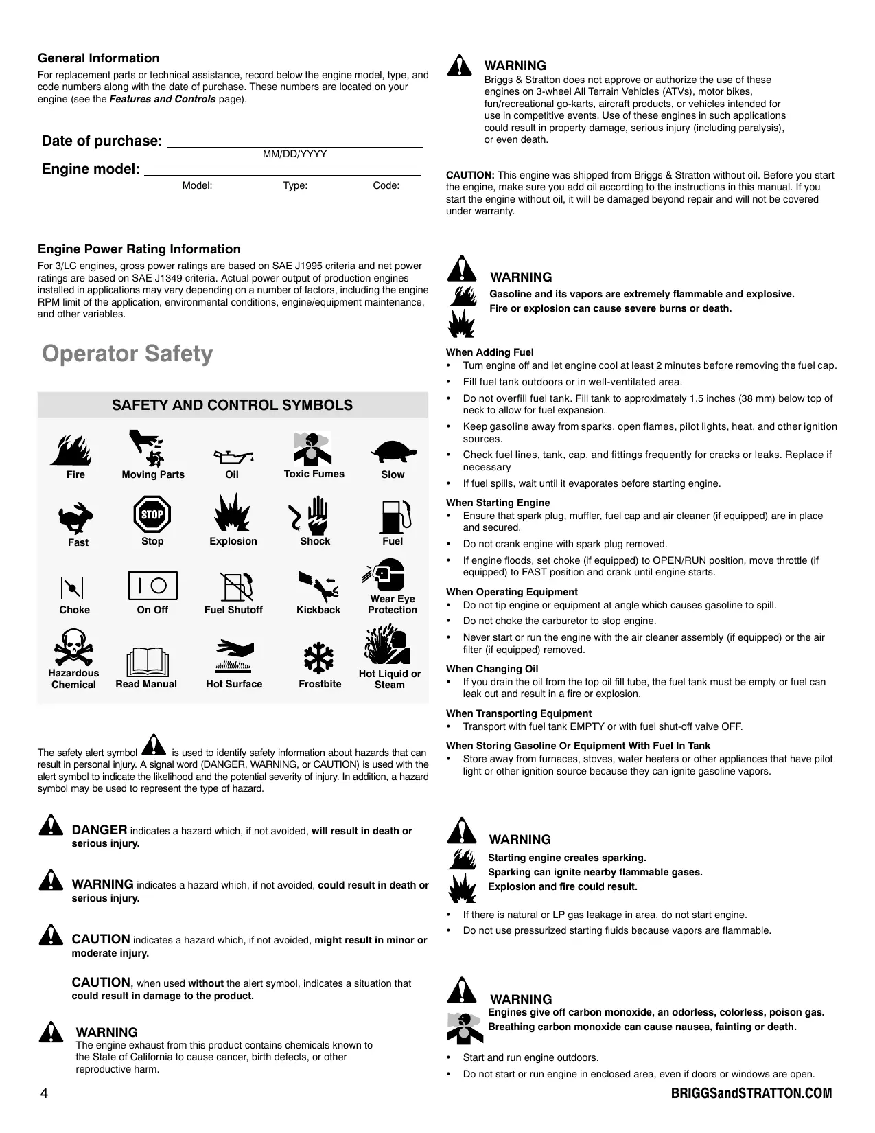
Compare the illustration 1 with your engine to familiarize yourself with the location of various features and controls.
A. Engine Identification Model Type Code
B. Engine Identification Date Code
C. Glow Plug
D. Dipstick
E. Oil Fill
F. Oil Filter
G. Oil Drain Plug
H. Injector Nozzle
I. Electric Starter
J. Injector Pump
K. Thermostat
L. Turbocharger
M. Oil Pan
N. Alternator
O. Coolant Temperature Sending Unit
P. Fan
Q. Fan Belt
R. Exhaust Manifold
S. Oil Cooler (if equipped)
Operation
Oil capacity (see the Specifications section)
Oil Recommendations
We recommend the use of Briggs & Stratton Warranty Certified oils for best performance. Other high-quality detergent oils are acceptable if classified for service CF or CF-4. Do not use special additives. Outdoor temperatures determine the proper oil viscosity for the engine. Use the chart to select the best viscosity for the outdoor temperature range expected.
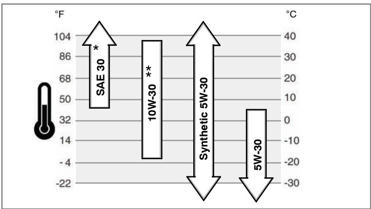
* Below 40^ (4^) the use of SAE 30 will result in hard starting.
** Above 80^ ( 27^ ) the use of 10W-30 may cause increased oil consumption. Check oil level more frequently.
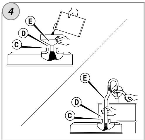
How To Check/Add Oil - Figure ② ④
Before adding or checking the oil
- Place engine level.
Clean the oil fill area of any debris. - Remove the dipstick (A) and wipe with a clean cloth (Figure 2).
- Completely insert the dipstick.
- Remove the dipstick and check the oil level. It should be at the FULL mark (B) on the dipstick.
- If low, remove the dipstick and add oil slowly into the engine oil fill (C). Do not overfill.
Important: When adding oil, adequate venting is required as follows:
- Remove the dipstick.
-
Make sure adequate clearance (D) is maintained between the oil fill device (E) and the engine oil fill (C). See Figure 4.
-
After adding oil, install the dipstick. Start and run engine at idle for five minutes. Shut off engine. Wait three minutes and check oil level. If required, add oil to bring oil level to the FULL mark (B) on the dipstick (Figure 2).
- Install the dipstick.
Oil Pressure
If the oil pressure is too low, a pressure switch (if equipped) will either stop the engine or activate a warning device on the equipment. If this occurs, stop the engine and check the oil level with the dipstick.
If the oil level is below the ADD mark, add oil until it reaches the FULL mark. Start the engine and check for proper pressure before continuing to operate.
If the oil level is between the ADD and FULL marks, do not start the engine. Contact any Briggs & Stratton 3/LC Authorized Dealer to have the oil pressure problem corrected.
Fuel Recommendations
Fuel must meet these requirements:
- This engine is certified to operate on diesel fuel. If incorrect fuel is used, black smoke, power loss, and damage to the engine will occur, which will not be covered by the warranty.
- Use clean, fresh diesel fuel with a minimum of 40 cetane. Fresh fuel prevents gum from forming in the fuel system. Purchase fuel in a quantity that can be used within 30 days. See the Storage section.
CAUTION: Do not use kerosene or gasoline instead of diesel fuel. Failure to observe this caution will damage the engine and void the engine warranty.
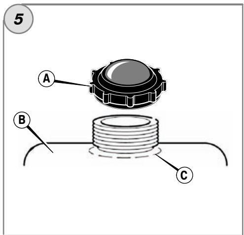
How To Add Fuel - Figure ⑤

WARNING
Fuel and its vapors are extremely flammable and explosive. Fire or explosion can cause severe burns or death.
When Adding Fuel
- Turn engine off and let engine cool at least 2 minutes before removing the fuel cap.
- Fill fuel tank outdoors or in well-ventilated area.
- Do not overfill fuel tank. Fill tank to approximately 1.5 inches (38 mm) below top of neck to allow for fuel expansion.
- Keep fuel away from sparks, open flames, pilot lights, heat, and other ignition sources.
- Check fuel lines, tank, cap, and fittings frequently for cracks or leaks. Replace if necessary.
If fuel spills, wait until it evaporates before starting engine. - Clean the fuel cap area of dirt and debris. Remove the fuel cap (A, Figure 5).
- Fill the fuel tank (B) with fuel. To allow for expansion of the fuel, do not fill above the bottom of the fuel tank neck (C).
- Reinstall the fuel cap.
Coolant Recommendations
Coolant capacity (see the equipment manufacture's manual)
Important: This is a liquid-cooled engine. A 50 / 50% mixture of phosphate-free antifreeze and tap water is required for cooling, rust resistance, and lubrication of the water pump.
How To Check/Add Coolant

WARNING
Severe thermal burns can occur by escaping steam or hot coolant.

- DO NOT remove radiator cap or reservoir cap if engine is warm or running.
- Stop engine and allow it to cool before removing radiator cap or reservoir cap and before changing or adding coolant.
- Before operating, check the coolant level. The coolant level must be between the FULL and the LOW/ADD marks on the coolant reservoir. If the coolant level is low, add a 50 / 50% coolant mixture of phosphate-free antifreeze and tap water to the reservoir.
- To remove the reservoir cap after engine is cool, place a thick cloth over the reservoir cap. Slowly turn the reservoir cap counterclockwise to remove.
-
If the reservoir is dry, then add coolant to both the reservoir and to the radiator. See the equipment manual for location, operation, and maintenance of the coolant reservoir and the radiator.
-
To remove the radiator cap after engine is cool, place a thick cloth over the radiator cap. Slowly turn the radiator cap counterclockwise to the first stop. If pressurized steam escapes from the cap, stand back to avoid injury. After all pressure is released, push down and turn the radiator cap counterclockwise to remove.
Gauges And Lights
The gauges and lights shown are typical and represent various options that can be used. See the equipment manual for location and operation of gauges and lights.

Coolant Temperature Gauge
Indicates coolant temperature when the electric start switch is in the ON position.
Normal range 80^ - 90^ C (175^ - 195^ F
Dangerous range above 105^ (220^)

Hour Meter Gauge
Indicates the total number of operating hours.

Fuel Gauge
Indicates the fuel remaining in the fuel tank. To minimize condensation, keep the fuel tank full.

Temperature Light
If the temperature light comes on, the engine is overheating. Stop the engine and check the coolant level (see the How To Check Coolant section). Check the radiator for debris that could restrict air flow.

Ignition Light
When the electric start switch is turned to the ON position, the ignition light should be on. When the engine is running, the ignition light should go out.
If the ignition light is out when then electric start switch in the ON position, check for a blown fuse.

Engine Oil Pressure Light
When the electric start switch is turned to the ON position, the engine oil pressure light should be on. When the engine is running, the engine oil
pressure light should go out. If the engine oil pressure light comes on when the engine is running, immediately stop the engine. First, check the oil level (see the How To Check/Add Oil section). Next, check the electrical system.

Charge Light
When the electric start switch is turned to the ON position, the charge light should be on. When the engine is running, the charge light should go out.
If the charge light comes on when the engine is running, check the electrical system.

Heat or Glow Light
When the ignition switch is turned to the heat/glow or the on position, the glow light will indicate to indicate that the glow plugs are preheating the
combustion chamber.

Fuel Filter Light
The fuel filter light comes on when excess water has collected in the fuel filter. The light should go out when the excess water is drained from the
fuel filter. If the fuel filter warning light illuminates while engine is running, stop the engine and drain the water from the fuel filter.
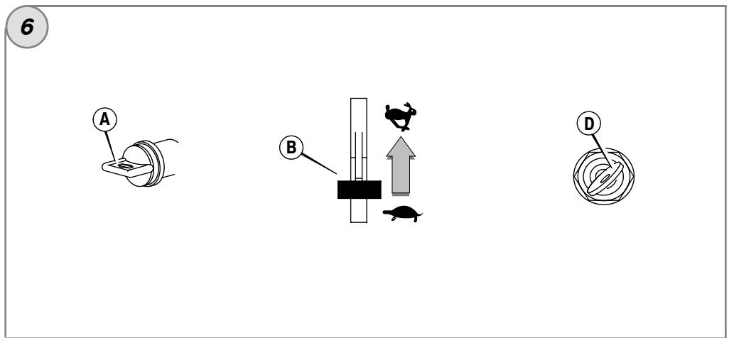
How To Start The Engine - Figure 6

WARNING


When Starting Engine
- Ensure that muffler, fuel cap, and air cleaner are in place and secured.
- If engine floods, set choke (if equipped) to open/run position, move throttle (if equipped) to fast position, and crank until engine starts.
- To prolong starter life, use short starting cycles, not to exceed 15 seconds per minute. Extended cranking can damage the starter motor.

WARNING

Engines give off carbon monoxide, an odorless, colorless, poison gas. Breathing carbon monoxide can cause nausea, fainting or death.
Start and run engine outdoors.
- Do not start or run engine in enclosed area, even if doors or windows are open.
CAUTION: This engine was shipped from Briggs & Stratton without oil. Before you start the engine, make sure you add oil according to the instructions in this manual. If you start the engine without oil, it will be damaged beyond repair and will not be covered under warranty.
CAUTION: Before starting the engine for the first time, charge the battery as
recommended by the equipment manufacturer. Failure to do so can cause damage to the engine.
Note: Some engines and equipment have remote controls. See the equipment manual for location and operation of remote controls.
- Check the oil level. See the How To Check/Add Oil section.
- Make sure equipment drive controls, if equipped, are disengaged.
- Turn the fuel shut-off valve (A), if equipped, to the on position (Figure 6).
- Move the throttle control (B) to the slow position.
Note: For starting in cold weather (below -10°C or 14°F), move the throttle control to the fast position.
- Turn the electric start key (D) to the ON or HEAT position (Figure 6). The glow light will indicate that the glow plugs are preheating the combustion chamber.
- When the glow light goes out, turn the electric start key to the START position.
CAUTION: To prolong starter life, use short starting cycles, not to exceed 15
seconds per minute. Extended cranking can damage the starter motor.
- When the engine starts, release the key. The glow light will illuminate for about 20 seconds and then go out.
CAUTION: Do not accelerate or race a cold engine. Failure to observe this caution can cause engine damage. - Allow the engine to run and warm up for several minutes before operating the equipment.
How To Stop The Engine - Figure

- Move the throttle control (B) to the slow position.
CAUTION: Before stopping a turbo-equipped engine, allow the engine to idle for one minute to cool the turbocharger. Failure to do so can damage the turbocharger. - Turn the key switch (D) to the off position (Figure 6). Remove the key and keep in a safe place out of the reach of children.
- After the engine stops, turn the fuel shut-off valve (A), if equipped, to the closed position.
Maintenance
Use only original equipment replacement parts. Other parts may not perform as well, may damage the unit, and may result in injury. In addition, use of other parts may void your warranty.
We recommend that you see any Briggs & Stratton 3/LC Authorized Dealer for all maintenance and service of the engine and engine parts.
CAUTION: All the components used to build this engine must remain in place for proper operation.
CAUTION: The manufacturer of the equipment on which this engine is installed specifies the top speed at which the engine will be operated. Do not exceed this speed.
Emissions Control
Maintenance, replacement, or repair of the emissions control devices and systems may be performed by any non-road engine repair establishment or individual.
However, to obtain "no charge" emissions control service, the work must be performed by a factory authorized dealer. See the Emissions Warranty.

WARNING
Unintentional start-up can result in entanglement, traumatic amputation, or laceration.
Fire hazard

Before performing adjustments or repairs:
- Disconnect battery at negative terminal (only engines with electric start.)
Use only correct tools. - Do not tamper with governor spring, links or other parts to increase engine speed.
- Replacement parts must be the same and installed in the same position as the original parts.
- Do not strike the flywheel with a hammer or hard object because the flywheel may later shatter during operation.
Maintenance Chart
Every 8 Hours or Daily
- Check engine oil level
- Check coolant level
First 50 Hours (initial Break-In)
Change engine oil *
Every 100 Hours
- Check fan belt tension
Clean radiator
Clean air filter - Check muffler and clean spark arrestor (if equipped)
Every 150 Hours
Change engine oil *
- Replace oil filter
Every 600 Hours or Annually
- Replace air filter
- Check valve clearance
Replace fuel filter
Every 1500 Hours
- Check injection nozzles
Annually
Change engine oil *
- Replace oil filter
- Change coolant
- Check fan belt tension
Clean radiator
- Check muffler and clean spark arrestor (if equipped)
- Replace air filter
- Replace fuel filter ▲
- Check valve clearance
- Service more often when operating under heavy load or in high temperature.
Follow the manufacturer's maintenance schedule if non-Briggs & Stratton part is used.
Service must be performed by an authorized DENSO dealer.
Not required unless engine performance problems are noted.
Inspect Muffler And Spark Arrester

WARNING

Running engines produce heat. Engine parts, especially muffler, become extremely hot.

Severe thermal burns can occur on contact.
Combustible debris, such as leaves, grass, brush, etc. can catch fire.
- Allow muffler, engine cylinder and fins to cool before touching.
- Remove accumulated debris from muffler area and cylinder area.
- Install and maintain in working order a spark arrester before using equipment on forest-covered, grass-covered, brush-covered unimproved land. The state of California requires this (Section 4442 of the California Public Resources Code). Other states may have similar laws. Federal laws apply on federal land.
Inspect the muffler for cracks, corrosion, or other damage. Remove the spark arrester, if equipped, and inspect for damage or carbon blockage. If replacement parts are required, make sure to use only original equipment replacement parts.

WARNING: Replacement parts must be the same and installed in the same
position as the original parts or fire could result.
How To Check Coolant
Important: This is a liquid cooled engine. A 50 / 50% coolant mixture of phosphate-free antifreeze and tap water is required for cooling, rust resistance, and lubrication of the water pump.

WARNING
Severe thermal burns can occur by escaping steam or hot coolant.

- DO NOT remove radiator cap or reservoir cap if engine is warm or running.
- Stop engine and allow it to cool before removing radiator cap or reservoir cap and before changing or adding coolant.
- Check the coolant level. The coolant level must be between the FULL and LOW, or ADD, marks on the coolant reservoir. If the coolant level is low, add a 50/50% coolant mixture of phosphate-free antifreeze and tap water to the reservoir.
- To remove the reservoir cap after engine is cool, place a thick cloth over the reservoir cap. Slowly turn the reservoir cap counterclockwise to remove.
- If the reservoir is dry, add coolant to both the reservoir and to the radiator. See the equipment manual for location, operation, and maintenance of the coolant reservoir and of the radiator.
- To remove the radiator cap after engine is cool, place a thick cloth over the radiator cap. Slowly turn the radiator cap counterclockwise to the first stop. If pressurized steam escapes from the cap, stand back to avoid injury. After all pressure is released, push down and turn the radiator cap counterclockwise to remove.
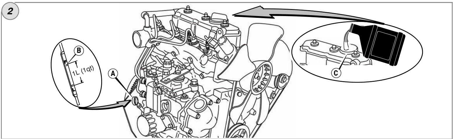
How To Change The Oil - Figure ② ③
CAUTION: Used oil is a hazardous waste product and must be disposed of properly. Do not discard with household waste. Check with your local authorities, service center, or dealer for safe disposal/recycling facilities.
Remove Oil
- Remove the oil drain plug (G, Figure 3). Drain the oil into an approved container.
- After the oil has drained, install and tighten the oil drain plug.
Change The Oil Filter
For replacement intervals, see the Maintenance chart.
- Drain the oil from the engine. See Remove Oil section.
- Remove the oil filter (H, Figure 3) and dispose of properly.
- Before you install the new oil filter, lightly lubricate the oil filter gasket with fresh, clean oil.
- Install the oil filter by hand until the gasket contacts the oil filter adapter, then tighten the oil filter 1/2 to 3/4 turns.
- Add oil. See Add Oil section.
Add Oil
- Place engine level.
Clean the oil fill area of any debris.
See the Specifications section for oil capacity. - Remove the dipstick (A, Figure 2).
-
Pour the oil slowly into the engine oil fill (C). Do not overfill. Important: When adding oil, adequate venting is required as follows:
-
Remove the dipstick.
-
Make sure adequate clearance (D) is maintained between the oil fill device (E) and the engine oil fill (C). See Figure 4.
-
After adding oil, install the dipstick. Start and run engine at idle for five minutes. Check for leaks. Shut off engine. Wait three minutes and check oil level. If required, add oil to bring oil level to the FULL mark (B) on the dipstick (Figure 2).
- Install the dipstick.
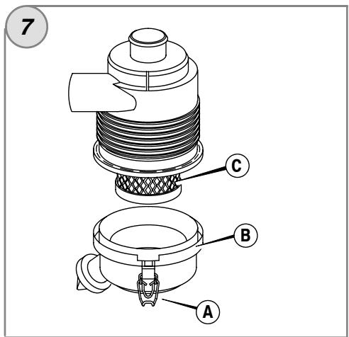
How To Service The Air Filter - Figure 7

WARNING
Fuel and its vapors are extremely flammable and explosive. Fire or explosion can cause severe burns or death.
- Never start or run the engine with the air cleaner assembly or the air filter removed. CAUTION: Do not use pressurized air or solvents to clean the filter. Pressurized air can damage the filter and solvents will dissolve the filter.
See the Maintenance Chart for service requirements. - Open the latches (A) and remove the cover (B). See Figure 7.
- Remove the air filter (C).
- To loosen debris, gently tap the air filter on a hard surface. If the air filter is excessively dirty, replace with a new air filter.
- Install the air filter.
- Install the cover and close the latches.

WARNING
Fuel and its vapors are extremely flammable and explosive. Fire or explosion can cause severe burns or death.
- Disconnect battery at negative terminal (only engines with electric start.)
- Keep fuel away from sparks, open flames, pilot lights, heat, and other ignition sources.
- Check fuel lines, tank, cap, and fittings frequently for cracks or leaks. Replace if necessary.
- Before replacing the fuel filter, drain the fuel tank or close the fuel shut-off valve.
- Replacement parts must be the same and installed in the same position as the original parts.
If fuel spills, wait until it evaporates before starting engine.
If the fuel filter warning light illuminates while the engine is running, stop the engine and drain water from fuel filter as follows:
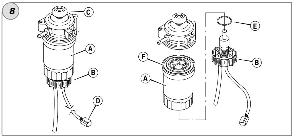
Replace fuel filter
- Disconnect the sensor wire (D).
- Remove the drain plug (B) and discard the O-ring (E).
- Remove the fuel filter (A) with a filter wrench.
- Install a new fuel filter by hand until gasket (F) contacts the housing. Then tighten an additional 1/3 turn.
- Install the drain plug with new O-ring.
- Connect the sensor wire.
- Activate the primer pump (C) until resistance is felt.
- Start the engine and check for leaks.
Drain water from fuel filter
- Stop the engine.
- Place a drain pan under the fuel filter (A) and loosen drain plug (B) approximately one turn.
- Water should drain from the fuel filter. If necessary, operate the primer pump (C) to drain water, but only until fuel flows from the fuel filter.
- Tighten the drain plug.
- Start the engine. Make sure that the warning light is off. Check for leaks.
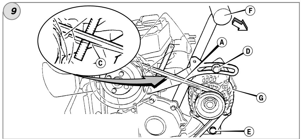
How To Check/Adjust The Fan Belt - Figure 9
Check Fan Belt
- Check the condition of the fan belt (A, Figure 9). If the fan belt has cracks or is damaged, replace with a new belt.
- Check the tension of the fan belt. Press on the center (C) of the fan belt. If tension is correct, the belt will move 3/8 - 1/2 in (10 - 12mm) if 22 lbs (10kg) of force is applied to the center of the belt. If the tension is too loose, adjust as follows.
Adjust Fan Belt Tension
- Loosen the alternator mounting bolts (D) and (E). See Figure 9.
- Position a pry bar (F) against the alternator (G) and the side of the engine block. To tighten the fan belt, pull on the pry bar. Temporarily tighten the alternator mounting bolts.
- Check the tension of the fan belt. See Check Fan Belt section. If necessary, repeat the procedure.
- Tighten the alternator mounting bolts. Torque bolt (D) to 14 ft-lbs (19 Nm). Torque bolt (E) to 45 ft-lbs (61 Nm).
Storage

WARNING
Fuel and its vapors are extremely flammable and explosive. Fire or explosion can cause severe burns or death.
When Storing Fuel Or Equipment With Fuel In Tank
- Store away from furnaces, stoves, water heaters or other appliances that have pilot lights or other ignition sources because they can ignite fuel vapors.
Engine Oil
While the engine is still warm, change the engine oil.
Troubleshooting
Need Assistance? Go to BRIGGSandSTRATTON.COM or call 1-800-233-3723.
Specifications
Engine Specifications
| Model | 520000 |
| Displacement | 51.87 ci (850 cc) |
| Bore | 2.677 in (68 mm) |
| Stroke | 3.071 in (78 mm) |
| Oil Capacity | 3.5 qt (3.3 L) |
Engine Specifications
| Model | 580000 |
| Displacement | 58.09 ci (953 cc) |
| Bore | 2.835 in (72 mm) |
| Stroke | 3.071 in (78 mm) |
| Oil Capacity | 3.5 qt (3.3 L) |
Tune-up Specifications *
| Model | 520000, 580000 |
| Intake Valve Clearance▲ | 0.008 in (0.2 mm) |
| Exhaust Valve Clearance▲ | 0.008 in (0.2 mm) |
- Engine power will decrease 3.5% for each 1,000 feet (300 meters) above sea level and 1% for each 10^ F( 5.6^ C) above 77^ F( 25^ C) . The engine will operate satisfactorily at an angle up to 15^ . Refer to the equipment operator's manual for safe allowable operating limits on slopes.
Check when engine is cold.
Common Service Parts
| Service Part | Part Number |
| Air Filter | 820263 |
| Oil Filter | 820314 |
| Fuel Filter | 820311 |
| V-Belt (940 mm) | 821075 |
| V-Belt (970 mm) | 820893 |
We recommend that you see any Briggs & Stratton 3/LC Authorized Dealer for all maintenance and service of the engine and engine parts. Use only genuine Briggs & Stratton parts.
LIMITED WARRANTY
Briggs & Stratton Corporation will repair or replace, free of charge, any part(s) of the engine that is defective in material or workmanship or both. Transportation charges on product submitted for repair or replacement under this warranty must be borne by purchaser. This warranty is effective for and is subject to the time periods and conditions stated below. For warranty service, find the nearest Authorized Briggs & Stratton 3/LC Service Dealer in our dealer locator map at BRIGGSandSTRATTON.COM, or by calling 1-800-233-3723, or as listed in the 'Yellow Pages'.
There is no other expressed warranty. Implied warranties, including those of merchantability and fitness for a particular purpose, are limited to one year from purchase, or to the extent permitted by law and all implied warranties are excluded. Liability for incidental or consequential damages are excluded to the extent exclusion is permitted by law. Some states or countries do not allow limitations on how long an implied warranty lasts, and some states or countries do not allow the exclusion or limitation of incidental or consequential damages, so the above limitation and exclusion may not apply to you. This warranty gives you specific legal rights and you may also have other rights which vary from state to state and country to country.
OUR PRODUCT
Warranty Period
Consumer and Commercial Use
Vanguard™ 3/LC
2 years
Major Parts Warranty *
3 years
Parts & Labor *
2 years
- Note the following special warranty periods: For purposes of this warranty policy, Parts & Labor coverage is 2 years. Major parts only coverage is extended through the third year of operation. Major Parts Warranty (M.P.W.) covers but is not limited to or exclusive to cylinder block, cylinder head, crankshaft, camshaft, gears, pistons, rods, flywheel, flywheel housing, oil pump, fan, pulleys, mechanical governor, intake manifold, and oil pan. M.P.W. does not cover and is not limited to piston rings, replaceable bearings, water pump, any electrical component, valve train components, accessory parts, seals, gaskets, carburetors, exhaust manifold, hoses, all fuel system components, injectors, injector pump, turbocharger, muffler, any filters, radiator, thermostat, spark plugs, glow plugs, and fuel transfer pumps. The warranty period begins on the date of purchase by the first retail consumer or commercial end user and continues for the period of time stated in the table above.
No warranty registration is necessary to obtain warranty on Briggs & Stratton products. Save your proof of purchase receipt. If you do not provide proof of the initial purchase date at the time warranty service is requested, the manufacturing date of the product will be used to determine the warranty period.
About Your Warranty
Briggs & Stratton welcomes warranty repair and apologizes to you for being inconveniently. Any Authorized Briggs & Stratton 3/LC Service Dealer may perform warranty repairs. Most warranty repairs are handled routinely, but sometimes requests for warranty service may not be appropriate. For example, warranty would not apply if engine damage occurred because of misuse, lack of routine maintenance, shipping, handling, warehousing or improper installation. Similarly, warranty is void if the serial number of the engine has been removed or the engine has been altered or modified.
If a customer differs with the decision of the Service Dealer, an investigation will be made to determine whether the warranty applies. Ask the Service Dealer to submit all supporting facts to his Distributor or the Factory for review. If the Distributor or the Factory decides that the claim is justified, the customer will be fully reimbursed for those items that are defective. To avoid misunderstanding which might occur between the customer and the Dealer, listed below are some of the causes of engine failure that the warranty does not cover.
Normal wear: Engines, like all mechanical devices, need periodic parts service and replacement to perform well. Warranty will not cover repair when normal use has exhausted the life of a part or an engine. Warranty would not apply if engine damage occurred because of misuse, lack of routine maintenance, shipping, handling, warehousing or improper installation. Similarly, warranty is void if the serial number of the engine has been removed or the engine has been altered or modified.
Improper maintenance: The life of an engine depends upon the conditions under which it operates, and the care it receives. Some applications, such as tillers, pumps and rotary mowers, are very often used in dusty or dirty conditions, which can cause what appears to be premature wear. Such wear, when caused by dirt, dust, spark plug cleaning grit, or other abrasive material that has entered the engine because of improper maintenance, is not covered by warranty.
This warranty covers engine related defective material and/or workmanship only, and not replacement or refund of the equipment to which the engine may be mounted. Nor does the warranty extend to repairs required because of:
1 Engines that are not properly applied to equipment. It is strongly recommended that the factory be contacted prior to applying a B&S 3/LC engine to equipment that did not originally use a B&S 3/LC engine.
2 Problems caused by parts that are not original Briggs & Stratton parts.
3 Equipment controls or installations that prevent starting, cause unsatisfactory engine performance, or shorten engine life. (Contact equipment manufacturer.)
4 Leaking carburetors, clogged fuel pipes or injectors, sticking valves, contaminated injector pumps, or other damage, caused by using contaminated or stale fuel. Use clean, fresh fuel (lead free gasoline, diesel fuel) and Briggs & Stratton fuel stabilizer, Part No. 5041.
5 Parts which are scored or broken because an engine was operated with insufficient or contaminated lubricating oil, or an incorrect grade of lubricating oil (Check oil level daily or after every 8 hours of operation. Refill when necessary and change oil and oil filter at recommended intervals). OIL GARD may not shut down running engine. Engine damage may occur if oil level is not properly maintained. Read Operator's Manual.
6 Repair or adjustment of associated parts or assemblies such as clutches, transmissions, remote controls, etc., which are not manufactured by Briggs & Stratton.
7 Damage or wear to parts caused by dirt, which entered the engine because of improper air cleaner maintenance, re-assembly, or use of a non-original air cleaner element or cartridge. At recommended intervals, clean and/or replace the filter as stated in the Operator's Manual.
8 Parts damaged by over-speeding, or overheating caused by grass, debris, or dirt, which plugs, clogs radiator or air cooling access openings, or damage caused by operating the engine in a confined area without sufficient ventilation. Engine damage caused by not using accurate mix of anti-freeze and tap water, or water entering the engine due to any cause.
Engine or equipment parts broken by excessive vibration caused by a loose engine mounting, loose cutter blades, unbalanced blades or loose or unbalanced impellers, improper attachment of equipment to engine crankshaft, over-speeding or other abuse in operation.
10 Routine tune-up or adjustment of the engine.
11 Engine or engine component failure, i.e., combustion chamber, valves, valve seats, valve guides, or burned starter motor windings, caused by the use of alternate fuels such as, liquified petroleum, natural gas, altered gasolines, etc.
Warranty service is available only through authorized service dealers by Briggs & Stratton Corporation. Locate your nearest Authorized Briggs & Stratton 3/LC Service Dealer in our dealer locator map on BRIGGSandSTRATTON.COM or by calling 1-800-233-3723, or as listed in the 'Yellow Pages'.
Briggs & Stratton Corporation (B&S), the California Air Resources Board (CARB) and the United States Environmental Protection Agency (U.S. EPA) Emission Control System Warranty Statement (Owner's Warranty Rights and Obligations)
Emissions control warranty coverage is applicable to certified model year 2007 and later engines, which are purchased and used in California, and to certified model year 2007 and later engines, which are purchased and used elsewhere in the United States.
California and United States Emission Control Warranty Statement
The California Air Resources Board (CARB), U.S. EPA and B&S are pleased to explain the Emission Control System Warranty on your model year 2007 and later off-road spark-ignition engine over 19kW (25HP). In California, new off-road large spark-ignition engines must be designed, built and equipped to meet the State's stringent anti-smog standards. Elsewhere in the United States, new Non-road spark-ignition engines over 19kW certified for model year 2007 and later, must meet similar standards set forth by the U.S. EPA. B&S must warrant the emission control system on your engine for the period of time listed below, provided there has been no abuse, neglect or improper maintenance of your engine.
Your emission control system includes parts such as the carburetor or fuel injection system, the air cleaner, ignition system, muffler, and catalytic converter. Also included may be hoses, belts, connectors and other emission related assemblies.
Where a warrantable condition exists, B&S will repair your engine at no cost to you including diagnosis, parts and labor.
Briggs & Stratton Emission Control Warranty Coverage
The 2007 and later off-road spark-ignition engines are warranted for two years.
If any emission-related part on your engine is defective, the part will be repaired or replaced by B&S.
Owner's Warranty Responsibilities
As the engine owner, you are responsible for the performance of the required maintenance listed in your Operating & Maintenance Instructions. B&S recommends that you retain all your receipts covering maintenance on your engine, but B&S cannot deny warranty solely for the lack of receipts or for your failure to ensure the performance of all scheduled maintenance.
As the engine owner, you should however be aware that B&S may deny you warranty coverage if your engine or a part has failed due to abuse, neglect, improper maintenance or unapproved modifications. You are responsible for presenting your engine to an Authorized B&S Service Dealer as soon as a problem exists. The warranty repairs should be completed in a reasonable amount of time, not to exceed 30 days. If you have questions regarding your warranty rights and responsibilities, you should contact a B&S Service Representative at 1-800-233-3723.
EMISSION COMPLIANCE PERIOD: 1000 HOURS
Briggs & Stratton Corporation Emission Control Warranty Provisions
The following are specific provisions relative to your Emission Control Warranty Coverage. It is in addition to the B&S engine warranty for non-regulated engines found in the Operating & Maintenance Instructions.
1. Warranted Parts
Coverage under this warranty extends only to the parts listed below (the emission control systems parts) to the extent these parts were present on the engine purchased.
a. Fuel Metering System
- Carburetor and internal parts (if applicable)
Cold start enrichment system (if applicable) - Fuel injection system (if applicable)
Air/fuel ratio feedback control system (if applicable) - Fuel pump
Fuel filter
b. Air Induction System
Air cleaner
Intake manifold
Throttle body (if applicable)
c. Ignition System
Spark plug
- Ignition coil
- Ignition processor (if applicable)
d. Exhaust System
- Exhaust manifold (if applicable)
e. Catalyst System
- Catalytic converter (if applicable)
f. Miscellaneous Items Used in Above System
Pressure, temperature, position, speed sensitive devices
Electronic controls
- Connectors and assemblies
Hoses
- Length of Coverage
B&S warrants to the initial owner and each subsequent purchaser that the Warranted Parts shall be free from defects in materials and workmanship which caused the failure of the Warranted Parts for a period of two years from the date the engine is delivered to a retail purchaser.
- No Charge
Repair or replacement of any Warranted Part will be performed at no charge to the owner, including diagnostic labor which leads to the determination that a Warranted Part is defective, if the diagnostic work is performed at an Authorized B&S Service Dealer. For emission warranty service, contact your nearest Authorized B&S Service Dealer as listed in the "Yellow Pages" under "Engines, Gasoline," "Gasoline Engines" "Lawn Mowers," or similar category.
- Claims and Coverage Exclusions
Warranty claims shall be filed in accordance with the provisions of the B&S Engine Warranty Policy. Warranty coverage shall be excluded for failures of Warranted Parts which are not original B&S parts or because of abuse, neglect or improper maintenance as set forth in the B&S Engine Warranty Policy. B&S is not liable to cover failures of Warranted Parts caused by the use of add-on, non-original, or modified parts.
- Maintenance
Any Warranted Part which is not scheduled for replacement as required maintenance or which is scheduled only for regular inspection to the effect of "repair or replace as necessary" shall be warranted as to defects for the warranty period. Any Warranted Part which is scheduled for replacement as required maintenance shall be warranted as to defects only for the period of time up to the first scheduled replacement for that part. Any replacement part that is equivalent in performance and durability may be used in the performance of any maintenance or repairs. The owner is responsible for the performance of all required maintenance, as defined in the B&S Operating & Maintenance Instructions.
- Consequential Coverage
Coverage hereunder shall extend to the failure of any engine components caused by the failure of any Warranted Part still under warranty.
Osha nHΦopMaun
3a pe3ePBNH qACTn IIN TExHuaCheKa NMOoi 3aIuHte NO-dOy MoDeNa, BNuA n KOobete Ha DnuIarTeJI C dataHa KynBuHaTeMy TeN iKOobe Ce hAmpuT Bbpy BaIHHBduIarTe. (BHXTE cTpaHnUATA EnMeHTN uypaBHeJIa).
Data Ha KynyBaHe:
MM/DAIITTT
Moden ha Dbratela:
Moden:
Tun:
KoI:
HOpMaIg 3a HOMHaIHaT a MoUHOCT Ha DBVaTeJIte
3aDbiratEnTe 3/LC (Tpi CININHDPBOv C BDOHO OXJAXDaHe) PbHnTaMoUHOCt Ce OCHOBABA h KpITepRInTe CByrIeAChO PtBavNnHaK J1995 HA SAE (DpyxjcETBO To h INHXEHPeOT o ABTOMObINHata npOMuHNHeOCT m TpaHCnOpTa), a POLE3HaTo MOnUHOCt - CByrIacHO KpITepRInTe OJ1349 h SAE. POLE3HaTn pOM3BOcTBHeMa MoUHOCt Ha DBrAteIN, MOHTnpAHn 3a paZmHnPiNIOKeHHo, MOXe Da BapnPaB 3aBNCIMoCT OT rONAM 6poi qakTopn, BKJIOHNTeHNO rpanHcHNe To ObOPOTn Ha npINOJXHH MEXAHN3bM, YCNOBHTA H OKOJHATA cpeDa, NODpBxxKaTa h DbrAteIN/obOpyDbaHETo n DpyrN npOMEHNBn.
Texhika 3a 6e3oNaChOCT Ha onepaTopa
CIMBOJIN 3A BE3ONACHOCT IN YYPABJIEHNE

Orheonacho

DbNxKeun Ce yactn

Macno

OToPbHn Ra3OBe

Бьрзи
обopotи

BabHN oboopOn

Cron

BzPbBOOnaCHO

Onachoc3a npaxeHHOT eNektpnueckn TOK

TopNo

Cmyka

Bkn. N3Kn.

PpekpatBahe abaheTo Ha rop

06paTeH yap

Ja ce hocat npedna3Hn Ovnila

Onachnyxumkaani

Ppoyete PboBOCTBO

Ropea noBbpxHOCT

OnachoctOT 3Mpb3BaHe

Iopeua Teuhoct mnpapa
IpeDynpTeHnHT CmBON 3a OAnCHOCT onpeDela IpeDoxpaHNTenHa nHΦpOmaUH 3a PCKOBe, KOITMO MOrAT Da IOBeDat DO HapAHBaHE Na IepcoHana. CnHahnsuapa Dyma (OPACHO, IPEYIPPEKDEHNE uN BHIMAHIE) ce noctabra 3aeHNO C npEynpeDnteHc HCMBON, 3a Da NOCOH BepoTHOCTTA i NOTEHuaHATA cepMO3HOCT Ha HapAHBaHETO. DOnbHnTeHNo, EInH CmBON 3a ONAHOCT MOKe da nOKa3BA BnDa Ha ONACHOCTTA.

ONACHO nocouba onachoct, korto, ako he 6bnde n36erhata, ue doBeede do cmbpt uH cepno3HO hapaHBAhe.

PNEyPExKHeHne nocOyBa onaCHOCT, KOaTo, aKe He 6bJe n36erHata, MoKe Da doBoeDo cMbpt Nn Cepno3Ho HapaHaBaHe.

BHIMAHHE nOCOyBa ONaCHOCT, KOrTo, aKo He 6bJe N36ErHata, MoXe da DOBeDe Do MaIka IIN cpeHa CTeneH Ha HapaHbAhe.
BHIMAHHE, n3no3BaHo 6e3 npEynpeDntENHn CmBON, noCOUBA cnTuacna, KOrTo 6n MoRNa da doBede do nobpeKdahe Ha npOdykta.

PNEyPPEKDEHNE
I3ropEnite ra306 ot To3n DInraTeN cbdbpKxat XmMueeCKn CbeDnHeNHa N3EcTHNa Ha ta KaNfOpHN KaTo npHnHnTeJn Ha paK, yBpeXdAnH np PaKaDaHe, nIi dpyrYyBpeXdaHn, CBbP3aHn C penpoDyKTHBHOCTTa.

PPEyPEXEHENE
Kopnpaunn Briggs & Stratton He Odobpna H ne I03bONBa n3noJ3BaHETO Ha Te3n DBIrAteJI BbPxy BCbExdoJI HA 3 KOJena, MOTOUKNETn, YBEcENIeNTN/KOJIUmK3a KaTpHTN, JTeaTEnH anapATn INI TpaHCnOpTN CpeCTBa 3a Yuactne B cBCTe3aTeHN MeponpuaTn. N3noJ3BaHTo Ha Te3n DBIrAteJIH HA TakINBA MaJInH MoKeJa Da BOdeE Do MaTePnaJIH YeTn, CepNO3Hn HapaHABaHn (BKJIOUChTEHNO npaJINa3) nDOn D No CMbpt.
BHIMAHHE: HactoanrT DnirateIe doctabr ot Briggs & Stratton 63 macno. Pnei Da cTAPrATpe DnIRATEJIe CE yBepTe, ye CTE Hanei MaN o Hero cnopei INCTpykunite B TOBA pkoBOcTBO.AKO rO cTAPrATpe 63 macno, ToJ ca ce NOBPe Ie 63 da 6bJe BbMOxHO da ce peMOHTnpa n rapaHunrtHa HMa da npokpBa. ueTaTa.

PNEyPPEKDEHNE

Béh3nHbT n Herobnte napn ca n3KJIouHTeJHo orHeonacn n 136yXnBn.
Ioxkap nJI B3pNB MOraT da npuHnHT cepNo3Hn ObrapHnN nIcmbpt.
PpI dOJImbaHe Ha rOpNB0
- ɪəʌnʌŋeTe DɪbɪræTJIŋ I rO octaBete Da ce OXlaɪn Haɪ-Maɪko 2 Mɪnʊtɪn, npeɪn Da CBAJInte Kanaʊkata Ha pe3εpBoap a 3a ropɪnBO.
-Пьн electe pe3epboapa 3a ropnBO ha OTkpnto nB do6pe BENTnnpaHOMeueHne.
He npbIbaiTe pe3epBoapaa 3a ropBIO. PbHete ro np6bn3nTeHo 1,5 Hua (38 mm) no-HNcKO oT roPnHra 6b Ha TbPbONHATA, 3a da nO3BOJNTe pa3wnpeHne HA rOpMBOTo.
-ДрьжteбенинадаунOTИСКР,OTKpTNПЯMbц,CINHANHЛAMN,TONHnHa nДугТЗаалNTENHnI3TOHnC.
IpoBepBaIte CheTo roPbONpOBoUnte,pe3epBoapa,kanaKaTaNcEINHeHnTa 3a NyKHaTHnHnNl TeOBe.3aMeHete n,aKe e Heo6xOdmo - Ako ropmboto ce pa3nee, n3aKaIte dokato TO ce n3napi, npedn da cTaptnape Dbratena.
PnCstaptnpaHn DnBnatae
- Vépepte ce, ce 3anaIeIeHATA cBeuI, IyMOnarLyIeHTen, KanaYcKata Ha pe3epBoapara 3a rOpBIO bB3dyHnHnФnTbp (aKOIMa TaKbB) ca HA MCTOTO CN ca o6e3oNaCehN.
He pa3BbptaIte DnBaTeTcN 3NaJIteHa CBeU. - Ako DBIRATEJNT CE 3aDABN, NOCTABeTe CMyKaaHa (aKO IMa TAKbB) Ha N03uIMRA OPEN/RUN, npINDbjKeTe pBuHata Ra3 (aKO IMa TAKaba) Ha N03uIMRA FAST IN pa3BbTnIte, DOkATO DBIRATEJNT cTAPtna.
Ppi pa6oTea MaunHa
He haknahnyTe Dniratena IIn MaunHaTa NOD bTbN, KOITOBIN DO pa3JIbAhe Ha 6eH3nHa.
He 3anyuBaIte kamepaTa Ha Kap6ypaTopa, 3a da cnpeTe DnirataTna.
- HmKora He CTapuPae I He pa6oTe C DmRAteJI npI DeMOHTnpAH KOMnNEKT Ha Bb3duHnIaФHb(pAOKIMTaKaB) INI cAMO Bb3duUWeHФnTbp(aKO IMMa TaKbB).
Pn CmehBaHe Ha MacNo
Ako n3TOyBaTe macnOTo OT rOpHata Tpb6a 3a nbJIHeHe C macNo, pe3eepBoapbT 3a BOBTO Tp6Ba Da 6bDe npa3Eh, INI To MOKe Ja noTEye I da npuHHN IOXap JI EKcNlNo3Ii.
Ptp TaHcnpOpTnpaHe Ha MaunHaTa
- TpahncopnpaTe c PPA3EH pe3epBoap, nIc KpaH 3a noJaBaHe Ha rOpBHO ha no3nua OFF.
Korato ckaiaipate 6eH3n Hn o6OpyDahe c roPbO B pe3epBoapa
CknAinpaTteJaTeOTnEaH,NEKIN,BOOHaRpeBaTeNIMIpyrEneKtpueeCKn np60pi, KOITOMATCNHAnHa NAMMaNIMDpyr3aANImTeJENm3TOHNN, 3auOTo TE Morat DaBb3nnAmEHT BcH3INHOBTe Napi.

PNEyPPEKDEHNE
IyckaheTo Ha IaBnraTeNa Cb3daBa NcKpeHe.
IckpeheTo MoKe Ia Bb3PnAmEn HAMnpaUte Ce HaOKoNo 3anaJIIMn ra3OBe.
ToBa moKe da doBeDe do ekCnNo3n noXap.
- Akma n3Tuahe Ha npirodeH nn BteuHn ra3 nponaB nomueHneTo, He cTaptnaTe DnraTeJI.
He n3no3BaIte ropnBa 3a NaaHNO 3aanlaBHe NOD HAnraHe, 3aOTo napTe IM ca 3anaJIteJIH.

PNEyPEXKDEHNE
BdIiBaHTo Ha BbIePoDeH Okc MoKe Da npuHn radeHe, npnAdbK nI IN Cmpt.
- Cтартураити паBOTeTeСДВИгАТЕН Habьн.
He cnapaTe n He pa6oTe Tc DnrgaTeIb B 3atBopeHo NomeeHne, dOpu npO tBOPeHn BpaTn nn np03Opu.

PNEyPEXKDEHNE

BbptTnTe Ce Yactn Moar Da Donpat Nm 3axBaHaT Pbue, KpaKa, Koca, oIeKIO IIN pInnaHdNExKHOCTn.
Mоже да се доctигнe до Трав matича amnytaцьи пл серною habаняbahe.
Pa60TeC dBnrgaTeJI npi nOCTabeHn 3aunTHn Kana.
-ДрьктpepbeteиКрака tcnДалуOTВьртуиceЧа'tN.
- PnBp3BaIe TdJIrIte Kocn CbAaIte yKpaSeHraTa.
He hocete no ce6e cn wipoko obneKno, Bncaun uHypoBe nIn Beun, KOITOMaT da 6bdat 3axBaHaTn.

PNEyPPEKDEHNE

Pa6oteuHte DnBraTeJN OTdJIaT TOIINHa. Yactne Ha DnBraTeJIte, OocboHo wymo3arLyuWnteJ, CTaBAT N3KJIIOHTeJIHO ropeu.

TOpHmTe OTnabTu, KaTo IInCTa, TpeBn, XpactaIak N dpyrN, Morat da ce 3anaJrT.
OCTaBeTe 7yM03aRn7uNtTeIa, 7nHbpaHa DnBraTeIa n pe6paTa da ce oxlaJAT, Ppei Da rDOKOCBaTe.
- Otrcpahe T haTpyanHte OTJOMKn OKOLO yMOn3aIyUWntEINu cInHHbpa.
- MohtupaIte n IpoIbpxkaIte B pa6OTHcBcTOnHne NckporacnteIra, ppeIa Ia3no3BaTe Dbrgate Hn 3aIaceHN MeCtA, 3aTpeBHeN PLOU, PLOUc Xpactn I Heo6pa6OteHn MeCTa. LtaTb KAIinOpHn N3MCKBa ToBa (B Pa3dE 4442 Ha KaInOpHnNCKn IpaBnIHNK 3a O6ueCTBeHN pecypcn). Bb3MoXHO e npyrn IaTn da IMAT IpoD6Hn 3aKOHn. FedePAnHte 3aKOHn ce npIinaRat Ha fedeepanHa TepHTOPIN.

PNEyPPEKDEHNE
Morat da ce noIyut cepno3Hn 3rapaHn OT oCbo6kDaBaauata ce napa nn ot ropeuata oxlaXdaa TeHocT.

HE CBAJIYIte KaanayKeTe OTo paDnAToPa IIn pe3epBoapa, Ako DniratJeT e ropeu nn pa6oTu.
Cnpete Dniratate nI rO octabeTe Da CE OXlaDi, npeDi ca CBaJIHe KanaUckITE Ha paAnatopa IIN pe3epBoapa I npei CmHaTa I IN HANBaHTo HO XLnAJaTaTeuHOCT.

PNEUYNPEXKDEHNE
CnyauHIO NCKpeHe MoKe Da IOBeDe Do NOxkap IIN Nopa3BaHe OT eNeKtpnueckn TOK.
HeBONHO cTAPTIPaHHe MOKe da doBeDe Do 3axBaUaHe, TpaBMaTHHa amnytaun IIN Do paHbAhe.
Onachoct ot noxap
Ipeu n3Bpwahe ha peryunpoBkn nonpaBkn:
- OtkaheTe KaBela Ha 3anaJIteJIHaTc CBeu n rO npbXTe daneY OT HeA.
- O Tkauhe Te M nHyc-Knlemata Ha akymyIaTopa (cAmO npn DnIraTeN C eJeKtpuYeckn cTapTep).
- IV3noJ3BaIte cAmO IOXoJauN INHCTpyMeHTN.
He 3actonopraBate c perynnapaata npyxina, loctobnte cnctemn nC npyrn qactn, 3a da nobunite oobopnte Ha dBiratela. - Pe3epBnHTe qactn Tp6Ba da 6bDaT cbC sbOTo KaueCTBO n da CE MOHTnpaT B CbUaT a N03uH, KAKTO opunHaHnHTe qactn.
- He ydprrte maxobnka c uyk nIIN TBbpr npedMeT, 3aTOTo ToJ MOKe da ce cTPOsi no BpeMe Ha pa6ota.
PnH3npo6BaHe 3a nckpa:
- I3noI3BaIte Oo6peH TnTtecTeP 3a Cbeu.
He npabete npoBepka 3a nckpa npn n3BaDeHa 3aapanTeHa Cbeu.
Elenentny uypablenia
CpaBHeTe NIOCTpaIraTa 1 C BaIMa DnIgAteN, 3a Da ce 3ano3HaTe c pa3NIoJIOXeHHeTO Ha pa3JIuNHHe EJEMEHTN UyPbAINHeH.
A. Mapknupobka Ha dBirataJIa Moen TnKoJ
B. Марк�орвka на Дагиателя Data Kod
C. Pódrpábaa CBeu
D. HUBONOKa3aTeN
E. OTBOP 3a HANIBaHe Ha MacNo
F. MaclenhФиntbP
G. Пробka 3a ИЗTOУBAне Ha macLoTO
H. JIO3a 3a BnpbckBaHe Ha rOpnBOTO
I. EneKtpnueckn cTapTeP
J. TOpINBO-HaHetaTHeHa NOMnA
K. Tepmoctat
L. Typ60kOmnpecop
M. KapTeP 3a macNoTo
N. AntepHaTop
O.Датук 3a Temпетатура淘汰хлaxдция areHT
P. BeHTnJaTOp
Q. Pembk 3a BEHTnJaTopa
R.ИЗпскатейенКОЕКТOP
S. Oxlaantel Ha MaCNoTO (aKo HMa TaKbB)
Pa6ota
Bmectmoct 3a macno (HnpaBte CnpBaKb B pa3deTexHuYecken DaHHN)
Пpenopьки 3a MacJIoTO
3a nonyubane Ha ha-n-do6pn Texnueckn nokaatenn npenopbvaame n3no3baheTo HA macnata Ha Briggs & Stratton c rapaunna n ceptnpukat 3a kauceTbo. Dpyrn BVCOKOKaeeCTBeHm Macna C mneu npicaKn ca pnpemlnBn, ako Ca KlaacMUnpaHn 3a pa6oTH PexkMn CF nI CF-4. Da he ce n3no3BaT cneuaJHn do6abKn. BbHnTe TEmnpaTyPOnpeJelT npabInHn BBC03ntET Ha macNoto 3a DbratateN. N3no3BaAte Ta6nmuTa, 3a da n36epeT ha-n-do6pn BNC03ntET 3a OcAKBHn Dnana3OH Ha BbHnHTe TEmnpaTyPn.
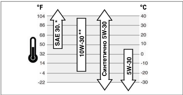
* Ako npn Temnepatypno 40F (4^) ce n3no3ba maclo SAE 30, toba ue doBede do Tpydno cTaptnpahe na Dniratelj.
** Питtemператуниху [27°C] Излобагену на масло 10 W-30 може по виший сонсуmaцята на масло. Роверразиные по чесу НИВОТУ MY.
Kak ce npoBepBa/HaIbBa MacNo -ФИгура 2 4
IpeiHaIBaHe IINI npOBepBaHe Ha MacJIoTO
Pa3noJoxTe XOpu3oHTaJIHO DvIraTeJIa.
- Почистете мостOTO OKОLO OTBopa 3a Налване на MacNo OT BCNUKN OTJOMKN.
1. CbaneTe HUNBONOKa3aTeJIa 3a MacITo (A) N fo N36bPwTe C YHCT PIIAT (FNyypa 2).
2.ИЗЦАЛБМьКНЕТЕНВОПОКАЗATEЛЯ3aTROPIBOTO.
3. Cbane HNBOKoKa3aTeI I npOBepe T HNBOTo Ha MaCnOTo. To Tp6Ba Da 6bJe do MapKnPOBkata FULL (B) Ha HNBOKoKa3aTeIa.
4. Ako e HnCKO, CBAIeTe HNBONOKa3aTeJI N haJIeTe BHNMaTeJIHO MaCIO npe3 OTBOPa 3a IIbJIHeNe Ha dBnIaTeJIe (C). He ro npenbIbaIte.
Baxho: KoraTo HauInBaTe MacNo, npaBnHTo BHTnInPnaHe ce NsICKBa, KaKTo CneBa:
CbaTe HNBONOKa3aTeJIra 3a MacJOTO.
- Y6eTe CE, Ye NOIbIbPkATE HUxHOTO pa3CTOHNHE (D) MEXy DpyHnraT3a haJIbMaHe HA mAcNo (E) u CTeHATA h OTBopa 3a IIbJIHeHe Ha DnBtAteJIA (C). BxKTe ΦNyrpa 4.
-
Cnéд наимbaheTo ha macnoto, noctabete HNBONOKaTeJI. CTaptnaIte n octabete DBNATeJI Da paobTu NET MmHTu Ha npa3EH XoJ. N3KJIIOUcTe DBnATeJI. N3yakaTe TpM MNHTu IN pOBepTe HNBOTo Ha macnTo. AKO ce HanaIra, HnaJIe Te OSe MaCNo, 3a Da DCtTnHa HNBOTo My Do MapKnipOBkATA FULL. (B) Bbpxy HNBONOKaTeJI (ФИгур2).
-
IocTabete HNBONOKa3aTeJHa MaCnOTo.
HaJrahe Ha MacJoto
Ako HNBOTO HA MACNOTO E MHORO HNCKO EHN DAHTNK 3A HANRAHE (aKO hMA TaKbB), MIO Ue Cnpe DnRATENI, IHI MOE 3A DeECTBA NAJAPMEHOTO MY cTPOCTBO. AKO TOBA CE CUYU, CNPTE DNRATENI N PNOBEPETHE HNBOTO HA MACNOTO C HNBONOK3A3TENI.
Ako HIBOTO Ha Macnoto E NOI MapKIpOBkata ADD, IO6abete MacNo, IOKaTO doCTHReMapKIpOBkata FULL. CtapTnpaIte DnBnateJ INpOBepeTe HAnraHTo, npEeI da IpoDbLnXitE da pAbOTHe.
Ako HIBOTO Ha macloto e mexdy MapknpoBknte ADD n FULL He cTaptnpaTe Dbratraten. Obphtete ce kMn HNKy uYbHMOohme npdctabraTeHa Briggs & Stratton 3a Dbratraten 3/LC, 3a da OTCtpanhe np6bneMa hanyaheto Ha macloto.
Ppenopbkn 3a ronpBOTO
TopNBTO Tp6Ba Da otROBapHa cJIeHNHe N3NCKBAHn:
To3n Dbraraten cbc septncikat 3a pa6ota c dnn3eNo BO ropnBO.AKO He ce m3no3Ba NOxOJaTO TROPBO MOKe Da ce NOnyUH CHepeH DNIM, 3ary6a Ha MOnHOCT N NOBPeHa HDBrAteJIa, KOATO HMa da 6bJe NOKPITa OT rapahnuraTa.
- I3noI3BaIte YIcTcO, npACHO, dI3eIIOBO rOpBBO C MHNHMaIHO ueTaHOBO YIcTcO 40. PpACHOTo rOpBBO ppeoTbPATA B O6pa3yBaHTo HA CMOna B rOpBbHata CnCTema. KyuBaIte rOpBBO KONJIeCTBO, KOeTO MoKe da Ce I3noI3Ba B pAMKInTe Ha 30 DnI. BIXTE pa3dEn CkIaNipAne.
BHIMAHNE: He n3no3BaIte Kepocn HJIN 6eH3nBMECTO n3eJIOBO rOpBO.
He3na3BaHTo Ha ToBa H3nCKBaHe BoN Do NOBpeHa DnBnraTeIa anynpaHe Ha rapaHnraTa My.
Kak ce HajiBa Macno - Fmrypa ⑤

PNEyPPEKDEHNE

TropBOTO NHEROBITE napn ca n3KJIIOHHTeINHO ORHEONACHN N36yXJIINB.
Ioxkap nIIN B3PnB MOraT da npuHnT cepNo3nObrapnHn nIcmbpt.
Ppi DJIINBaHe Ha rOpNBo
- ɪЗклочete Двигатели n I O octaBeTe Da ce oxlaДи hai-Majko 2 MmHytn, npeДи da CBaJIte KanaykaTа Ha pe3epBoapa 3a roPnBO.
- Пьнete pe3epboapa 3a ropnBO ha OTkpnto nIN B do6pe BeHTnnpaHO nOMEseHne.
He npenbIbIaIe pe3epBoapaa 3a roPbIO. PblHETe ro np6bn3ntelHO 1,5 HHa (38 mm) no-HNcKO OTo rOpHnra Pb6 Ha TbplOBnHaTa, 3a da No3BOJte pa3wnpeHne HA roPbBOTo.
-ДрьжтеторвOTOдалецOTИСКРи,OTКРNTINПамьц,CИгнанилamп, TOnnHaHиДугиЗаалNTeHLNИ3TOUHnI. - PpOBePbAaTe Ye cTo roPbONpOBoUnte, pe3epBoaap, KaanuKaTa n CbeHHeHnTa 3a pyKHaTnHn I TeOBE. 3aMeHnTe rAn oKeHo6xOdmo.
- Ako ropmboto ce pa3nee, n3aKaIte dokaTo TO ce n3napi, npedn da cTaptnape DInraTeI.
- MocHTeTne npOaTHCTBOTO OKOJI KANAqKAATA Na p3eepoApa 3a ropINO BT MPcSOTNI HACNOBBAHN.CbANETe KANaKAPaA (A, DInypra 5).
- HanbIhTe pe3epBoapa 3a ropINO (B) c ropINO. 3a da no3boInTe pa3uHpeHne ha ropINOTo, He nbHeTe Hd doJIHaT aOCHoBa Ha rbPNOHnTa 3a HaNBaHe ha ropINO (C).
- NocTabete 6paTHo KanaaKaTa.
Ppenopbkn 3a oxlaekdaeta Teuhoct
BmecTmOcT 3a oxJaxJaauTa TeuHoc (BnXTe PbKOBoCTBTO 3a pa6oTa Ha npOn3BOInTeHa na o6OpyDbaHeTo)
Baxho: Toba e Dniraten, Oxlanqan C oxlanqdaa TeHocT. 50/50% cmeoT Hecbdpjkaa fccpaTu aHTnOprn3 n BOdnpoBOHa BODa e Hc6bXoIma 3a Oxlanqdahe, OcnpyBaHe yCTOnuHBOCTTa Ha KOpO3nI n Cma3BaHeTo Ha BoDHaT oNOMna.
Kak ce npOBepraBa/haJIbBa oxJaXDaIaTa TeuHOCT

PNEyPPEKDEHNE

Morat da ce noIyut cepno3Hn 3rnapnO tOCbo6kdaBaaata ce napa nn ot ropeuata oxlaackdaa TeHocT.

HE CBAJIAYTE KanaayKeTe OTo paDnAtopa IIn pe3epBoapa, Ako DniratJeT e ropeu nn pa6oTu.
Cnpete Dbriratena I ro octabete Da ce OxnaI, npdeI ca cBaJIHe KanaaKInTe Ha paIaIatopa IIN pe3epBOapA IN ppeI CmHaTa IIN HAIbHaTe HO OxlaXdauTa TeyHOT.
1. Праздау,在охлaxdaata TeHocT.НьOTO u Tpr6ba
da 6bde Мжду Маркпорвкite FULL n LOW/ADD, OTблзани habepeBoapra 3a
oxlaJdaanza TeHocT.Ако НьOTO u E HnCKO,налеite B pe3epBoapra 50/50%
Смс ot anHtppn3,КоTo He CBdPka ФocpaTN BOа OВODCha6nTeHnata
mpexka.
- 3a da cbaJIne TKe ana KaTaHa Ra6eepBoapA, CneI KaTo DBrnAteIeT E OXnaIeH, NOCTabete Napue De6eB I nIat Bbpy HcE. BHmATEHIO A OTBNIte B NocOKa, ObaPaH a DaBIXeHNeTO Ha CAcOBHNKOBATA CTPEKNA.
- Ako pe3epeBoapbTe npa3eH,doJeIe B Hero N B paJnaTopo oxJaaTa TeHOCT. HanpaBeTe cnpBaK b PbkOBOCTBTO 3a pa60Ta C o6OpyDbaHeTo OTHOcho pa3nOJoxKeHMeTo,po60TaTaNpDpJbXKaTHa pe3epeBoapaN paJnaTopo 3a OxJaXDaUaTe THeOCT.
- 3a da cbañite Kanaúkata Ha paáñatopα, cnei KaTo dBiratelaT e oxlaedn, noctabete naphe debeI nIAT pBxpy He. BInmaTeHIO r OTbniTE B NOCOKA, o6paTHa H DaNBIXeHNTo HA cacOBHKnOBaTa CTpeNka Do IIpBPOTU cnpaHe. Ako ND He i3n3a npa Ipo Nd HApIaHe, 3actaHete Ha3ad, 3a Da I36BerHe TnapaHbAHe. Cnei Kato HAnraHete CnAHe, HATNCHEte KanaúKATA Ha padNaTopa HADONY I a OTBniTE B NOCOKA, o6paTHa Ha dBixKeHMeTo Ha cacOBHKnOBaTa CTpeNka.
I3mepBaTeJIHn ypeDN i CBETJIINHHN INHdNKaTOPN
Ioka3aHnTe I3MePbATEHNHypeDNi NCETNIHHN INHINKaTOpN caCTaNapTHN i CbueCTByBAT B pa3NIHNN OINiM, KOHTo MORAT Da 6bDat N3NO3BaHn. HanpaBeTe cnpBaKbA B PbKOBOcTBOTO 3a pa6Ota C o6OpyDbaHETO OTHOCHO pa3NoJIOKeHnEO paboTaTAMIM.

TepMometbpo 3a oxJaKaDaaTa TeuHOCT
Показва Temпера typа на охлaxдашатугост, korогот контейнат Клич с поимя ON (Вкл.). Hopмален 06xbat - 80° - 90°C (175° - 195° F) Onaceн 06xbat - Нд 105° C (220° F)

Yacobn6poa
OTHTa cymapnna 6poi pa60TH nucoBe.

I3mepBaTeJEn ypeed 3a HaJIuHOrROPBO
Ioka3BaOCTaBauIoTO Bpe3epBoaparopnBO.3a daHamaInTe KOHN3aunraTa HbOa, BnHarnIOndbpxajTe nIbnHepe3epBoap.

CBeTInHeH INHdNkaTop 3a TemnepaTypa
Ako CBETNIHHNAT INHDMKATOP 3a Temnepatypata CBETHE,3NAU, YDE BnBAtenat e nperepAn. Cnpete DnBtareTne Npopebete HNBOto HAoxNaDauTaTe TcHOT (Bxte paoEpa
OxnaJaata TeHocT).IpoBepBaIte paIaIatopa 3a HacIOBaHN, KOITMOrata da OparruAT B3dyuHnI NOTOK.

CBeTJIHHeH INDnKaTOP 3a 3anaJIbAHe
Korato KOHTAKTHNAT KJIIOU e Ha NO3nIaON (BKnL.)CBETNIHHNRT INHINKATOP 3a 3anaIbAbe TpR6Ba DA cBTN. LOM DBNRATENRT 3apa6OTM, BNTpR6Ba da Ia3rache.AKO INHINKATOpBT He cBTN pRi KOHTAKTEH KJIOU aON (BKnL.) npOBepeTe 3a n3rOPI npEtnaNTen.

CBeTtHnEH nHnKaKOp 3a ha MacNToB bDnRaTeIe Korato KOHTAKTHNAT KIOUe hA no3nZm4 ON (BKn.), CBeTtHnHHnT HnHnKaKOp 3a HnAHaTHeTO hA macNTo TpRb6A da CBtN. IOM
Дигателт Зарботи, CBETINHнглгИНДКATOP 3a HANIIGAHETO Ha MacNTo TpR6Ba DA 3aRaCte. AKO CBETINHnHNgT INDIIKATOp 3a HANIIGAHETO Ha MACNTo CBeTI npi pa6toeДиgatel, He3a6abHNO ro cnpete. ПьрBo npOBepe HbBOTo Ha macNTo (HapabeTe cnpaBak Ba pazdelen KaK e npOBepBaHaHnBaMaNo). CneI ToBA npOBepe eJekTpueckata cntema.

CBeTJInHeH INHnKAtOp 3a 3apeXdaHe
Korato KOHTaKTTHnT KJIIOU e Ha N03uIN ON (BKnL).CBETNIHHNt INHnKATOp 3a 3apeJdaHe TpI6Ba Da CBETn. LOM DnRatEnT
3apa60tn, INHdkaTopbT Tp6ba Da n3rache. Ako CBetJINHHnT INHdkaTop 3a 3apeKdaHETo CBeTI np pa6Oteu DnurTaIe, IpOBepTe eNEktpueckata cnCTema.

CnHaJIHa JAmNa 3a HarpeBHa CBeu
Korato KOHTAKTHIANT KIIOU e Ha no3uHne heat/glow nIIN no3uHn ON, CINHAHATA lamna ue noka3Ba, Ye harpeBhnte Cbeu npedbapntelHO opOBHNTa Kamepa.

CBeTInHeH INdkaTop 3a fNtBpa 3a rOpNBO
CBeTINHHNAT INHnKaTOP 3aΦnITbpa Ha rOpBOTO CBETBa, KOraTO BvB ΦnITbpa ce e HacbpaIa MHOr BOJa. INHnKaTOPbT TpRbBa da
3araChe, KORAto nIINHnata BOda CE nI3OuN oT fIITbpa 3a rOpIBOTO. Ako CBETJINHHNAT INIKaKATOP 3a fIITbpa H oR npIBOTC BcETHe, KORAto DIBrAteJIr T pa60TN, CIPeTe DIBrAteJIr N I3OTcE To BODATA O T fIITbpa 3a rOpIBOTO.
Kak ce cnapa Dnrgatele - Fnrpa 6

PNEyPPEKDEHNE

TOpNBOTO NHEROBNTe napn ca N3KJIIOHHTeHNO ORHeONaCHN N36yXJIbN.

Tóxkap iNIN B3pNB MOraT da npuHnT cepNo3HN o6rapnHn IIN CMbpt.
PnCTaptnpaHneHaDbiratena
Vbepete ce, ye ymuO3aIpyuIHT, kanaKhata Ha pe3epBoapa 3a rOpBO n Bb3duHnT fUJIITbP ca Ha MeCTaTa UIM u Ca do6pe 3akpenen.
- Ako DBVrataTeTc Ce 3a,dabn, noCTabeTe CmykaHa (aKO Ima TaKbB) Ha nO3uHn open/Run, pnpDbXeTe PbHnata Ra3 (aKO Ima TAkaba) Ha nO3uHn "fast" npa3bPTaTne, DOkATO DBVrataTe TcstnpHa.
3a da npOdbIJIKTe KJIBOTA Ha cTapepa, 3nON3BaJIte KpaTK cTapTOBn UIKJN, He no-dIbIgnt ot 15 cek/MH. PpOdbIJIKTeHNO pa3bPtaHe moKeJa nOBpeDi cTapepa.

PNEyPPEKDEHNE

Дигатеите Изneyсат Вьгелорodeн OKИС, КОТо e OTpoBEH ra3, 6e3 МИрИС И CBRT.
BdmbaHTo Ha BbIepeDoH Okc MoKe da npuHHn radeHe, npnaDbK nIn Cmpt.
- CtraptnapeTne npabOTeC dBnrgateJHaBbH.
He cIapTnapeTe n He paBoTeTe C DniratelaB 3aTbOpeH OmeueHne, Iopn n npn OTbOpEH BpaTn nn np03Opu.
BHMHAHVE: HactoansIATBnIaTeIe DoctabrO t Briggs & Stratton 6e3 macNo. Pnei Da cTAPtIaTe DnBraTeIa Ce yBepeTe, ye Cte Hane IMaNo B Hero cnopei nHCTpyKuInTE B TOBA pkoBOcTBO.AKO rCtAPtIaTe 6e3 macNo, ToJ uca ce NOBPeIe 6e3 da 6bDe Bb3MOxHO da CE peMOHTnpa I rapaHunTa HmJa da NOKpNbA zetaTa.
BHMMAHME: IpeDn Da CTApTnpaTe DnIraTEna 3a IbPbN bT, 3apeDeTe akymnaTopa, kako Te CpneOpBvO BA TpOnBIOJNTeHa NAbOpyBaHToE. Hec3nA3BaHETO HA TOBA N3McKBaMe OMOX Da pnnHH NOpeBa Ha DBrgATenr.
3a6eJekka: HЯкои Двгагети и оборудане сcaбденис усточьа 3a дuctанциону упавленье. Hanpabete cnpaВКа в БкOBODCTBOTO 3a pa60ta c obopydbaheTo 3a pa3noJokxeHMeTo n pa6Otatac yсточьanta 3a duCTahunHOH ynpablenHe.
- Поберете НВОТо Ha macLOTO.Наразоветспавka в раздаЯ Кк сьпоберяBa/HaHbMa MacNo.
- YBepete ce, ye 3aDbNkBaunTe ynpabNeHnHa o6OpyDbaHTo, aKO nMa TaKnBa, ca N3KnIOHeHn.
- 3aBpTeTe KpaHcTo 3a noDaBaHe Ha rOpIbO (A), aKO nMa TaKOba, Ha no3nur "on" (Фигур6).
- Пемецпесу лоста на рьчата ra3 (B) на позци slow
3a6eJka: 3a cTapTnape B cTyDoH bpeMe (noi -10° C nIu 14° F), noCTabete
IocTa 3a pbUHATA ra3 Ha no3nizma fast
- 3abptete KIOUa 3a eIeKpUeCKn CTapTe (D) Ha no3uON n HHEAT (Hypa 6). CnHaHnHaT a lamna 3a Cbeunte ue noKaJe, ye noDrpaBauNTe Cbeun npedBaRrJEnHO 3aqrBAt rOpBnHata KamaPe.
- Μιος Σηραλήνα ΜλΑΜΝΑ 3a CБΕψΙΤΕ 3aRaçΗ, 3aBbρΤΕ ΚλΙΟΥα Μ Ελεκτριχέκης Κιαρθερ Μ ΦΟπιμί ΜΑΓΑΓ.
BHIMAHNE: 3a da npoDbJnxTe JxNBOTa h cTapTepa, n3noI3BaIe Te KpATKc cTAPTOBnKIn, He no-DbItn O15 cek/MH. PnpObJnxKeTIHOTOp a3bTpAHe MOJE da nobpei cTApTepa.
- Korato DBirateTATCTAPnA,OCB6oTe KIOUa.CINHAnHata lamna ue CBETHe 3a OKONO 20 cekyHnI n CLEd TOBA ue 3arache.
BHHMAHNE: He nodaabaTe ra3 n He noBuaaBaIte o6OpOTne Ha cTyedn DbinaTe. Hecna3BaHeTo Na TOBA n3nCKBaHe MOKe da npuHn NOBpeHa dAnBaTaeTn. - Octabete DbiraTeJIaT da paobTu n da 3arpee B npoDbIxHeHne Ha HrkONKo MNHyTu, npeDi Da ce paobTu c o6OpyDaHeto.
Kak da cnpete DnurateJna - Fmrgpa 6
- Ппемстete поста на рьчната ra3 (В) на поцли slow
BHIMAHME:П repd n cnpahe Na dBa ratae n C Tybokomnpecop, ro octabeTe ha 6abHn 6obotn 3a OkOJ eOna MnHyTa, 3a De oeXnAa TpybokomnpecopbT. Pp nponyck H TOBA DeIcTBne TybokomnpecopbT MoKe Da ce NobpeDn. - 3abptete KIOUa (D) Ha no3nua off (n3Kn.) (ΦIrypa 6). CbaTe KIOUa n ro dpbXte Ha be3oNaCHO mCTO, daJeu OT o6cera Ha deua.
- Cnep cnipane Ha nBiratene, 3aBpTeTe KpaHcTo 3a noDaBaHe Ha rOpBBO (A), aKO mTaKOBa, Ha 3aTBopeHa No3mua.
TexHnuecko obcnykBahe
I3non3BaIe cmoOpnHnHnpe3epBnHuactn. DpyrHuactn MoKe da He cpa60Tt Do6pe, MOKe Da noBpeJr DBIratae n da doBeaTdo HapaHbAbe. Ocben ToBA, I3non3BaHeTo Ha npyr Huactn MoKe da anyInp a rapaHunra Tn. Hne Bn npenopbUhame Da nocTeNe HAKOIOT YnbHINOMOeHIne TpeDctabHTeHn Hn Briggs & Stratton 3a BmHKn Onepaunio N ToxEHmueCKOTO u cepBn3HOto oCbnyKBaHe I DBiratela 3/LC n pe3epBnHe TaCTn.
BHIMAHHE: BcNkK KOMNOHENTn, n3non3BaHN npn pOn3BODCTBOTO Ha TO3n DBiratTeI, Tpa6Ba Da 6bDat Ha MCTOTO cN 3a npabunHaTa My pa60ta.
BHIMAHME:Помбовдениг на оборуданeto,на КОЕТО.To3NДВИГATEENGEБдЕМоHTIpan,ОпЕДELЯ MAKCIMANHITE OOBOPOTN,ПрINΚОТУ SEpaBOTN DBIVATeRЯТ. He NaBbuaabaTe T63nOBOPOTN.
KoHTpOHa eMnCnIte
Iopdpbxxkata,cmHATA nIN pEmoHTbT Ha yCTpoiCTBaTa 3a KOHTPOHa BpeHNTE emCNMORAT da 6bDat N3BbPwBAHn OT BCEK pEmoHTEN CEx nIN texHnK, pEmoHTnpaunz DInrAteN, KOnTO He cNtON3BaT 3a TpaHCNOPTn CEm. Bce naK, 3a Da nOJyUHne "6e3nnLaTHo" o6cnYkBaHe Ha yCTpoiCTBaTa 3a KOHTPOHa BpeHNTE emCNMn, pa60Tata Tp8Ba da 6bJe n3BbPwEha OT YbNHOMOuEhen 3aBODCKn npdctabnten. Hanpabete cnpaBcVa B yapauuNTa OTHCHO BpeHNTE emCNM.


PPEyIPEXDEHNE
HeBONHO cTAPTIPaHHe MOKe da IOBeDe Do 3axBaUaHe, TpaBMaTHHa amnyTaunI nn Do paHbAhe.
Onachoct ot noxkap
Ipeu n3BbPbBaHe ha peryunpOBKn nonpaBKn:
- O Tkauhe Te M nyc-Knemata Ha akymyntopa (cAmO npn DniratEn C eNeKtpueckn cTapTeP).
- I3noI3BaIte cAmo IOxOJaIu INHCTpyMeHTN.
He 3actonopbaite c perynnapaata npyxina, loctobute cnctemn nIc npynuactn, 3a da nobunite oobopotne Ha dBirateJIa. - Pe3epBnHTe TpaTb6Ba Da bDaT CbC CbIOTO KaueCTBO N Da CE MOHTnPaT B CbIaTa No3uNIA, KAKTO OpiunHaHnTe TaCTN.
- He ydpnTe maxoBnKa c uK nIi TBbpN ppeMET, 3aIoTO ToI MoKe da Ce CTpoShn no Bpeme Ha paOba.
CmHa Ha MacJIeHnФJITbP
OTHOCHO INTEPBALNTe 3a CmHaTMy HnPaBete CnpabKa B KapTaTATEXHHecko 06CNIYKBaHe.
1.ИЗТоУВанеHaMACЛOTOOTДВИАтЕЯ.HanpaBeteCnpaВkaВpa3дeNИЗТоУВанeHaMACЛOTO.
2. CbanelteMaclenHnIeH (H, Hpya3) n ro deNoHpaTe no noXoJaHnHaunH.
- Ппедида моHTирате HOвИ МаСЛЕн ФИNTьр, ЛЕК Oмжete ФИNTьрНATA rapHNTypa C HОВО, YИСТСО МАЛNO.
- MohtnpaIte MaclenHnФnTbp Ha pBka,doKaTo rapHnTypa Onpe BbBФnTbpHnAaIaTpep, cnei KoETo ro 3aterHeTe c oue 1/2 do 3/4 o6opota.
- HanaBaHe Ha macNo. HanpaBeTe cnpaBka B pa3JeH aHa macNo.
HaHnBaHe Ha MacJo
Pa3noJIOXeTe xOpn3OHTaJIHO DnBraTeJIa.
- Почисту мостOTO OKОLO OTBopa 3a Налвае на MacJO OTO BCNUK ONTJOMKN.
Hampabete cnpabka Ba p3denn Texnueckn daHHN OTHOCHO BmectHMOCCTTA 3a macnoto.
- CbaIeTe HbONoka3aTeJIa (A,ФИгура 2).
- Hajeite BnmaTeHIO macIoto B dBirataTeI pye3 OTbopa 3a nbHeHe (C). He npenbIbaIte.
Baxho:Korato Hauinbate Macno, npabunHBo BHTnIpaHe ce 3NCKBa,KaKTo cneBa:
CbaJeTe HbONOKa3aTeJIa 3a MacIto.
- Y6eTe CE, Ye NOIdbpxkATE HxHHTO pa3cTOrHHe (D) MEXydy FyHnraTa 3a NaIbMaBe Ha MaCNo (E) i CTeHATA Ha OTBopa 3a IIbJIHeHa DAbratEna (C). BxKTe ΦNyrpa 4.
- CnéД haɪnɪbaHéTo ha macIto, noCTaBte HɪBONOKa3aTeJIr. CTapɪnpaɪteɪ octabete ἡBɪrαTelaɪ Da paθoɪn Ἱη MɪHγtɪ Na ἠpəsɛh Xɔd. ΠρOBepeTe 3a TeʊObe. IɜKlɪoHTe DɪBraTelaɪ. Iɜsʌkæte Tpɪ n MɪHγtɪ N ΠρOBepeTe HɪBOTO Ha macIto. Ako ce Hɑlaɪra, HaneiTe Oüe MaCNo, 3a ἀdoCTɪŋhe HɪBOTO My do MapKnipobkata FULL (B) Bbpxy HɪBONOKa3aTeJIr (Φnɪpya 2).
- NocTabete HNBONOKaTeNaHa MacNoto.
Kak da ce o6cnykBa Bb3duhnaФnltbp-Фnrgpa 7

PNEyPEXKDEHNE
TogIBOTO HHEROBITE napc ca N3KNIQUHTeHNO ORHEONACHN N36yXnBn.
Iopkap IIN B3pNB MOraT Da npuHnHT cepno3Hn ObrapnHn IIN CmbpT.
Hikora He cTaptnape Te He pa6oTe C Dniratena npu OTcpanen KOMnneKHa Bb3dyuHn4 pntbp.
BHIMAHNE: He n3nON3BauTe CbrCTeH Bb3dYx NIN pa3TbOpNTEn, 3a da NOChCTBaTe fNtba. CbrCTeHnT Bb3dYx MOKe da NOpeDn fNtTa, a pa3TbOpNTeTo ra3TbAPrt.
OTHOCHO3NCKBaHnra 3a cepBn3HO 06cnyXbaHe, HnpaBeTe cnpabKa B Kaprata 3a texHnueckoto 06cnyXbaHe.
- OTBOpTe cHKcatOpnte (A) n cBaJIte Te KanaKa (B). BnKTe ΦIrgypa 7.
- CbaJIeTe Bb3dUwHnA qmIITbp (C).
- 3a da OTCTpaHNTe HACNORBAHnra, BHMMATEHNO NOyKBAITE Bb3dUHHIN φmTTbp Bbpx Tbprda IOBbpxHOCT. Ako e npekaIeHO 3ambpcEH, CMeHETe rC HOB φmTTbp.
- MoHTpaIte Bb3dUshnHnФnTbp.
- NocTabete Kanaka n 3aTbOpTe dKcatOpnte.
KaK ce cMeHЯФиNTbpa 3a ropnBO -ФИrgya 8

PNEyPPEKDEHNE
TOpIBOTO HcEROBnTe nap ca n3KlIOuHTeJIHO orHeONaChn n 36yXnBn.
Iopkap IIN B3pNB MORaT Da npuHnHT cepno3Hn ObrapnHn IIN CMBpt.
- OTKaueTe MInHyc-KJIeMaTa Ha akymyIaTopa (cAmO npn DniratEn C eJeKtpuYeckn cTapTep).
- DpBxTe rOpBOTO daney OTOCKPn,OTKpnTn PnAmbuc, CnHaHn IaMnI, TOnnHaN aDpyr 3anaJIteHn n3ToOHnU.
- Поверразьше чсго chopьробдente, peзрьога, калачкати Cбединенята 3а рунати и тсчоб. 3amehnte ng ako e heo6xodmo.
- ПразсmaHa Na Фпгтba 3a ГориВ, ИЗTOчЕ peЗерваора 3a ГориВ ИИ 3aTbOpe TkaHcTe 3a NOdAbaHe Ha ГориВ.
- Pe3epBnHTe qaTn TpRbBa da 6bDaT CbC bSToTO KaYeCTBO n Da CE MOHTnpaT B CbUata P03nui, KAKTO OpiuHaHnHTe qaTn.
Ako ronpmboto ce pa3nee, n3yakaiTe okaTo To ce n3napi, npedn da cTaptnape Dbratena.
AOKBETNIHHNRTnpEduynpeJdaaUHdNKatOp3aФnITbpaHa rOpNBOTCBETHE, DOKATO dBiratelTAPoBTu, CNpTeToIuN3TOHTeBODataOTΦnITbpa3a rOpNBOTO, KAkTOcNEBa:
CmeHete nIbpa 3a rOpBOTO
- Pa3eɪnHeTe npOBoDnɪka Ha daTnuɪka D.
- CbaIeTe npo6kata 3a u3ToUBaHe (B) u n3xBbPnTe O-tpbCTeHa (E).
- CbaIeTe bpa 3a roPbTO (A) C raeuehen KIOU 3a bp.
- MohtnpaTe HOB 3a RopBoTb Ha pSka,doKaTo raphHtypata (F) Onpe B KAPTepa.CneI ToBa 3aterHeTe OdoJbnTeHInJeO C ouee1/3 o6Opot.
- MoHTnpaIte np6kata 3a n3TOUbaHe c HOB O- npbCTeH.
- CBbpxKe KaBeJa Ha daTnuKa.
-
3aèiCTbaIe IoKaUBaIaT aIOMna (C),doKaTO yceITe CbnpOTBJIeHne.
-
CtraptupaTe DniratTeN npOBepe 3a TeObe.
I3toe Boata ot hnltbpa 3a ropnboto
- Cnpete dBuraTeJIa.
2.Пocstabete BaHATA 3a n3TOUBAHe noIФИТьpa 3a rOpINBO (A)и pa3xJa6eTe np6kata 3a n3TOUBAHe (B)сОКОЕ EDIN O6OpOT. - Bóda tprhba da nIteue OT φnITbpa 3a ropINO. Ako e Heo6xOJIMO, 3aIeICTBaIte NOkAuaBaaIa TOMNA (C), 3a da I3TOUHTe BOJa, HO cAmO DOKaTOnOTEHe rOPINO OT φnITbpa.
- 3aterhete np6kata 3a n3TOUbaHe.
- CstaptnaTe DniratEnyBepTe ce, Ye npdeynpeHnHaTa lamna 3aracBa. PpoBepTe 3a TeOBe.
Kak ce npOBepBa/peryInpa pembka Ha
BeHTnlaTopa -FHyrpa 9
Поберразе на ремьka на BeHTnilatopa
- Поверете сбстонуTo (A,Фигура 9).Ако по ремьka на вентларopa ИmaNYKHATINH Или e NOВpeDeH, CMEHETe ro C HOB.
- Поверете onьbaheTo ha pembka Ha BeHTnlaTopa.HaTncHeTe cpeata (C)Ha pembka Ha BEHTnlaTopa.Ako ontbaHeto e npabuInho, cpeDAta Ha pembka ue ce npemecTbAc 3/8-1/2 nHa (10-12 mm) npn npinlarae Ha 22 naYnda (10 kg) cnla BByxH er. Ako ontbaHeto e cna6o, perynipraTe ro kakTo cneDbA.
Perynipahe Ha onbbaHeTo Ha pembKa Ha BEHTnlaTopa
- Pa3xna6eTe MOHTaXHnTe 6oJItoBe Ha aIntepHaTopa (D) u (E). BuxTe Φnrgya 9.
- NocstabeTe MOHTaxHa aHaRa (F) Cpeu ayntepaToPa (G) n cTpaHata ha 6noka Ha dBiratena.3a da oBtHeTe pembKa ha BcHTnlaToP, n3terJeTe MOHTxHaTa aHa.3aTeHerTe BpemHoHO MOHTaxHnTe BOINTObe Ha aTnePtoP.
- Поверете ольbaheTo ha peMbka Ha BeHTnilaTopa. HanpaBete cnpaBaKa b paZdelenповеркаHa peMbkaHa BeHTnilaTopa.AkO ce Hana, noBtopeTe npOeDypata.
- 3aterHete MOHTaXHnTe 6oIToBe Ha anTePHaTOpa. 3aterHeTe 6oIa (D) C bBPTau MOMeT O T 14 naHydpyTa (19 Nm). 3aterHete 6oIa (E) C bBPTau MOMeT O T 45 naHydpyTa (61 Nm).
CknaipaHe

PNEyPPEKDEHNE
TognBoto HceroBnte nap ca n3KlHHTeHNO orHeonacn n 36yXnBn.
Ioxkap uIN B3pNB MOraT da npuHnT cepNo3n ObrapHHN uIN CMBpT.
PnCknaDnpaHe Ha ropBO nIHa MaunHa c ropBO B pe3epBoapa
CknAinpaTteJaleNOTeNn,NEKn,BOOHaRpeBaTeNnIINDpyrEneKtpueckn npi6oBn,KOITOnIMATcHnAHnIaMnnIy3NaJIaTIeNnI3TOHnIz3aOToTeMOrAT DaB3nIAmHeHTm3ApEnHrTaT O rOpBOTO.
MacnotoHaDnrgateTna
DOKATO DBNATENT E BCE OUe TOnbl CMEHETe MACNOTO.
OTKpNbAHe n OTCTpaHbAbe Ha Hen3npaBHOCTM
HyckaTeJIncceOTnmo?PioceteteBRIGGSandSTRATTON.COMIINCeO6aTeHa1-800-233-3723.
Cneunfukkaun 3a Dnuratela
| Моden | 520000 |
| РавOTEN obem | 51,87 in³ (850 cm³) |
| Въtrightchoose димаMuTьр на силиндьра | 2,677 in (68 mm) |
| РавOTEN xOD на уталOTO | 3,071 in (78 mm) |
| Вмост immunost за масло | 3,5 qt (3,3 L) |
CneuΦnkaun 3a Dnuratae
| Моden | 580000 |
| РавOTEN OБЕМ | 58,09 in³ (953 cm³) |
| Въtrightchoose диамetedр на симпдьра | 2,835 in (72 mm) |
| РавOTEN XOD на буталOTO | 3,071 in (78 mm) |
| Вмост immunost за масло | 3,5 qt (3,3 L) |
PeryInpOBbUHN daHnn*
3a JIyHOn TbproBcKO non3BaHe
Двигаел Vanguard™ 3/LC
2roDnHn
Гаранцяз ocHOBnЧа'tN\*
3roDnHn
Pe3epBnH qactn n Bnlaran Tpyd
2roDnHn
* OTeBnHexe TcneHnTcneuHn rapanuHnHn nepnoi: 3a ueHnHe Na Ta3n rapaHnOHHa NOnHTNka, nOKpntHeTo 3a pe3epBNHe TAcTHn BnAraHnAT 3a zamHnata IM tryE 3a nepNOd OT 2 roHN. Camo 3a ocHOBnHE peseBPbN HCTn rapaHnOHHO TOpKpNTMe e p3aUnpeHo n 3a TptTaTpa 00Ha. rapanuHtta 3a ochBnHTte cactn (I.O.O) noKpNbA, HO He CE orapAnuHabe EaHCTBeHn BO CAMO Do cnInHDPOBn 6bOk, cnInHDPOBa TnaBa, KOJIeHnatBa Ban, p3apReJeINTEJHnBA B3bHnIpeDABKn, 6yTaJATA, MOTOBUNKHe, MAXOBnKA, KOKyXHa 3a MAXOBnA, Macehena TOMNa, BEHTINAtopa, pEmbUnHte uaiBm, MexauHnPeYrNaTOp, CMyKaTeJHnK OKeKTOP u MacceHnA KapTer. I.O. He noKpNbA He CE orapAnuBa EInHCTBeHO n CAmO 3a 6ytAlHnTE CeMentn, Cmehemite NaepR, BoHDnA To NOMn, BCEKN ELEMENT OT ENEKTPueckCATA INCTaLauZn, 3aDbNKBaunTe ELEMEnTn 3a KlananHnTE CNOMarATEENHTe ChAs, YNlTBHeHnTA, raphHTpyNTe, KApSypatOPnte, KOKeLPTa 3a NfROpeJInTe rAOBoDn BCNUKn ELEMEnTn Ha rOpNBbTA CStema, pa3npbCKBaNTe DOn3n, HarHeTaTeHNaTTO NOMn, Typ6okomnpcecopa, ymuOzArJyNtwnEi, BCNUKn FInTPn, PAadNaTopa, TepMOCTATA, ZanlanEnHnTE CBEUH, HarpBeaTeHNHe CBeUH NOMPNTe 3a NpOdaBHe HA npBO. RapAnuONHnT nepNo d 3anoVb AT DaTata Na KyuBaHe OT PbBnNotpe6bITe H Na Dpe6HO mnn ON TYkNyBaVa 3a TpbroBcK n eJin N npOdbJxBa Ka TepNoDA ON BpeMe, fncKcpan B ropHaT aTabla.
He e He6xOIMMa pernctpaunHa rapaHuaTn, 3a da ce nolnyrnapaHIOHO 6cnyXbaHe 3a npdyKTte Ha Briggs & Stratton. Ia3ete 3a doka3atenCTBO KNTAHUOT OT NOKyNkata.Ako HE ocnpytde Oka3atenCTBO 3a HauhHata DaHa KynyBaHe, pni nonckBaHe Ha rapaHIOHO 6cnyXbaHe, datata Ha nponBODCTBO Ha npdyKTA ige 6bJe 3nON3BHa 3a onpeJelne Ha rapaHIOHHn nepMDo.
OTHOCHO Baaata rapaHnra
Briggs & Stratton npHemAT c roTOBHOCT rapaHUNOHnI pMOHT n CE n3BnHBat 3a npHInHETO Bn HeyIO6CTBO. BCEKo TOpINiPAH cEBPn3EN npeCDtABITe H a Briggs & Stratton MozeJa dOcbJeTb nRAPUONOHnTE pMOHTn Ha DBrAteJIte3/LC. NobeHTo rapaHOnOHn pMOHTn Ce npOBExdAT pyTHNO, HO NoHNKA O e B3MOXHO nCKAHNTa 3a rapaHNoOHn CEBM3HO o6cJyXBaHe a He ca ONpaBdAn. HanpIMep, rapaHnI HA da Ce npIN3Hae, aKO nobPeDA t B DVBaTeJIe Ce bJLnKn Ha HEnpaBnIH na yN0TpeBA, ha IINCA h PEOBHO TEXMHNECKO o6cJyKBaHe, Ha HEnpaBnIH TOAcapTIPaHene, MaHEbpinae IN CKNaDIPAhe INI Ha HEkAeCTBeH MOHTxK. CbIoTo Taka, rapaHnITaCe rHyBu, aKO cepINiHNT HOMep Ha DVBaTeJI e OTCTpaHE NII ca npaBeHH npOMEHI NO CAMNI DBrAteJIen.
Ako kynbvaht he e cbrnace h cpeweHneTo ha Cepbn3Hn npdctabnten, ue ce hnapabn pnooybahe, 3a da ce yctanobin dani rapaHnTae npni3hAb. NsckBaHTe OT Cepbn3Hn npdctCTabtna I da npoctOtabn 3a npereN BcNCHKOn DOnbIyNTENH
paKTn Ha cboa nDCTPBvTOp INi Ha 3aOda. Ako DnCTPbVTOpBt INi 3aBODt peuH,
ye TOBA nCKaHa e OnpabDaHO, Kynbvaht se bde HnblHO o63ueTeH 3a
deFekTHnTE qactn. 3a da ce n36eTHe HeOpa3yMeHNeTo, KOeTO MOKe Da Bb3HNKHe
MexJy KynbvaHa u npdctABTIneY, NO-dONy ca n36poEHn HkON OT pnuHnHTe 3a
NoBPeDA B dBiratEJI, KOIO TepaHnTJIrTa HE NOKpIBA.
HopmaHnO n3HocBaHe: DnBraTeJIte, KaKTO BCNUKm MEXaHnHn UcTPOCTBA, Ce HxJdaT OI nepiOnHa 3aMaHa Ha cactN IO BCnyBaHe, 3a Da pa6oTATIO6pe. FapauHnTa He NOKPbA pEmoHTA, KORATO pniu HOPMAHn I3HOBCaHae DAeHa cact NII DnBraTeRt CA i3eepnAn JXWBToCn. FapauHnTa He ce pnpnaHa, Ako B DnBraTeAe Ccynu NOBpeDa, NpApDn HENpaBnHNo ON3BaHe NNOTCbCTBne HA pyTHnHa NOdPbXkA, TPAHCNPtIpaHe, MaHNyIpaHe, CbXpaHrBaHe NN He npabIneH MoTak. CbIo TaKa, rapaunHrTa Ce ry6n, Ako cepinHnrT Homep Ha DnBraTeJe oCTpAHe INI no Hero ca NapeBHe nPomehn.
Henpabnno noodbpxhae: XIBOTbHa daaHd BniratTeI 3aBnCt OT yCNoBnTAp, pni KOnTO paobTo n OT prNkteKo, KOTo nOlyuYaba. HaKo npInIOxEnKa, KaTO KUYTHBaTOPn, NOMn, INOTAUMHn KOCaQyN, MHOrO cTeO CE uN0n3BaT B nPaaHn a 3ambpceha CpeDa, KoTo moKeJa da OOBeDo npDeBapntEHLHOTo IM N3HOCBaHe. TaKoBA m3HOcBaHe He cOpKnBa OT raPahmTa, KORA To CE dJfXn HA MPbCOTn, npax, aba3nBa 3a NoCHCTBaHe Ha CBeTuHa IpyrN abpa3nBnM MaTePnaIi, nonaHaJIb n D BniratTeI nopAei HeKaeeCTBEHO nOndbPxHae.
Ta3n rapaunna NOKPbBa cAmO yNtpe6eB V DBrataJIe DeEkeTeH MaepnA n/INn I3pAbOTKa, a He 3aMnHaTaN INN Bb3CTAHOBRAHETO Ha MauHHATA, KbM KOrTO DnRATeIaT MoKe Da 6bJe MOHTnpaH. RapaunraTa He NOKPbNA nNONCKAN pEmONTN PanoJa:
1 IbIrataJI, KOIto He ca npabInHO MOHTnpaHn KbM 3aDbNkBaHaTa MaunHa. HactoYuBO ce npenOpBvA nePdBaPntHeO da ce o6bPheTe KbM 3aBoDa, KORAto ue MoHTnpaTe 3-UINHIDpOB dBIRaTeC BOHO oxJaXaBe B&S 3/LC KbM MaunHa, KOIto He nON3Ba, no Haanyo, DbratEn B&S 3/LC.
2 Поблеми, пчинен OT части, кontо He ca opигиннч actи Ha Briggs & Stratton.
3 YcTPOIeCTBA 3a ynpabLeHHe Na MaunHATA NJI CbOpXeHHN, KOtO npceHa T CTApTnPaHTo H Na DmTa, BOJrD NO He3aDOBONHTENHATA m paBOta IIN cKbCBAT XJBOTMa Y. (KOHcyNTPnAte Ce C npon3BOUInTe Ha yCTOPICTBa.)
4 Kap6byaTOpn c TeOBe, 3aIpbctEni npBoOni nII pa3npbckBaun iIO3n 3a roPBOTo, 3aJIeHNJI KLnAHI, 3aMbpceHn HaHTeTEnH NOMNI INI INpYra IOBpe, pIuINHeNAOT 3aMbpcEHO nII pIcTeHNO roPBO. YIoTpe6BaIte UcTO, pIaCHO ropBO (6eH3N 6e3 cbJbpxAHne Ha ONoB, dN3eNo BO ropBO) n CTa6NJMaTAp HO ropBO Briggs & Stratton c KaTANOKeH No 5041.
5 7actn, KOnTo ca NaIpaHn IInn ChyHEn, 3aIoTO DnBraTeJrT e pa6OtnI c HeIOCTaTbHyO INn 3aMbpcHeo MaCNo, INn C MacNo C HNOxOJaIO KaEcTBO (PiOBepBaIte EgeJHEBHO HnBOTO HA MacNoto INn CNEd BCEKIN 8 caca pa6Ota. Korato e Heo6xoJIMO, DOJIbAaTE INcMeHNe IMeTAOIO INmacENHnФINTPb Ha npenopbYBaHNT INTEpBaJIn OT BpeM). ABapHInOTo yCTpoCTBO OIL GARD MOKeJa DA He CNPe p6oTeUIM DaBraTeN. Ako HnBOTO Ha MacNoto HE ce NODbPjka ToHNO, DnBraTeJrT MoKe Jda Ce NOBpeJi. PioyEtTe PbKOBOCTBO T3 aPa6Ota.
6 PEmOH NT nIpyERnPAHe Na MOHTnpAHn cactH IIN arperaTu KaTO cBeHNHTeIN, npEdaBaTeENm MExaHN3Mn, INCTaHUNOHn ynpabJeHnI nDp., KOnTo He ca npOa3BeHnOt o Briggs & Stratton.
7 NOBpeHa IINI IN3HOCBaHe Ha Yactn, npuHHeHn OT HeNCTOTn, nOaHnA B DVBnFATeJI, NOpaIe HKeAueCTBeHO IOdIbPxaHe HA Bb3DyUHnH FInTbp, HEKaueCTBEN IOBTOpeMOnTAEIOITNOJ3BaHe HA HeOpunHnAHn EEmeHTn 3a FInTbpa. Ha npenOpYbaHnTE INHTepBaHn OT BpMe IONUCTBAITE WnIIM CmEHRABte FInTbpa, KaKTo e INoCooHb BOkoBDCTBOTO 3a pa60Ta.
8 8aTn, noBpeHn npaDi HaDbWseHn MaKcImaJIHn oObOpTu IINI npaI npEprBaHe, Dblkao Ce Ha TpeBn, HacNoBaHn IINI 3aMbpcBaHe, KOtTO 3nyuBbAT, 3aDpCTbAT paNAtopa IIN OTBOPTe 3a DOCTbn HA OXNAkDaIHH Bb3dyx, IINIOBpeA, DblkaaCe Ha paBoTa B 3aTbOpeHO pOcTpaHCTBO C HeOCTaBtuHa BEHTInaIaI. NopBaPeHa DAbratEnI, DblkaaCe Ha HeCNa3BaHETo HA TOHOTo CbOTHOSeHne Ha aHTncPmI INITeHn BOda IINI Ha npOHKnBaHETo HA BOaB Hero No HЯKaKBA npuYnHa.
9 7actnHaDbnraTeHaIIMaunHata,CyynenHOTpekomepHaBbpaunia, DbljkaaSe Hc HaXna6abMOHTax HA DbnraTeHa, Xna6abnpeXeuaH NOKOB, Xna6abn pIacTmHn Xna6abn IIN3Je banaHCnpaHpaOtoTH KOnela,Ha HeNoDbo KynPiPaeHa MaNaHATA KbM KOENaTNABaH Na DnBaTeHa,Ha CbpxbxCOKnOobOpHe nnIpyra 3noynotpe6a npiaabo.
10 PyTHINHa HacTpoIka n peryInpOBKa Ha dBnIaTeJIa.
11 Поврета на дыгатял Ии на Heroь сementsТ.е. ropmba камера, Кларани, Кларанни Легл, Кларани Воради, Ил Исторелу hamotkn Ha CTAPETe рогади Ипалзваген.To anTepeHATINBHN roPbA KaTo HaФтА, npipOden ra3, БeshИнсnpOMeHEN KauceCTBa T.N.T.
「rapaunOHTo cepBn3HO o6cIyKBaHe e DocbHIO eINHCTBeHO ue3 OtpnHpaHte CepBn3N npedctabntEn Ha Kopnpapra Briggs & Stratton. HamepeTe hai-6n3Kn Otpn3HpaHcebpBn3e npedctabntEn 3a dBnratente 3/LC B hawaT yka3aTeHa Kapta 3a npedctabntEnite Ha aDpec BRIGGSandSTRATTON.COM, mnn Kato ce o6aHte Ha TeI. 1-800-233-3723, nni KaKTO e nocOeHO B,,XbIITne CTpaHnIUM"
Vseobecné informace
Pries jjungiant varikli
Pries jjungiant varikli
Bo n36eJahne BOCIJIaMeHEHnI napOB 6eH3nHa xpaHHTe ERO BdAIN OT KOTIOB, neeH, BOHOHaRpeBaTeHnI npOuH nPiObOPoB, B KOToPbX NCNOLb3YeCTcR opeKnA INI INHOI NCTOCHNK BOCIJIaMeHEHnI.

OCTOPOXKHO
Pn3zanycke DnuraTeIa IponCxOuT 06pa3oBaHne NCKpbI.
06pa3oBaHne NcKpbI MoKET Bbl3BaTb BOCJIaMeHeHne ropUOuX ra3OB.
3To moKTe npBecTe N B3pbIbY n noXapy.
He 3anyckaTe DnBaTeIb B TOM MeCTe, rIe npOnCxOaNT yTeHka npnpOHO rIN CxNKeHHOro ra3a.
He nCnoJIb3yIte nycKOBblE XnIκOCTn B a3pO3oJIbHOr ynaKOBKe, TAK KaK INx napbl OrHeONaChbl.

OCTOPOXHO
BbIXlonHbIe ra3bl cOepKgat OKncb yrIepoDa - 6ecuBeTHbI n He IMeOUsn 3anaXa IdoOBtBuIra3.
BbixaHne OKcn yrIepoJa (yrapHoro ra3a) MoKET BbI3BaTb pBOTy, notepio co3HaHn IIN cMeptb.
3anyckaTe n 3kcnpyaTnpyTe Dnrgatelb BHe NOMEeHna.
He 3anyckai Te Dbratel B nomseHn daxe npri OTKpbItbIX OKhax nDbepx.

OCTOPOXHO
BpaaiooieeaeTajn Moryt BOHTN B KOHTAK C yPKAM, HORAM, BONOCAM, Odekdo N ee Akceccyapamu NIN 3axBATNTb IX.
3TO MOXET PnBecTN K TpaBMaTHueCKoAMnyTaun NJIIN TJAKeIbIM pBAHbIM paHAM.
He 3KcnpnyatpyuTe o6opuyoBaHne 6e3 yctaHOBJIeHHbIX 3aunTHbIX npncnOco6NeHni.
He npibnkaite pykn n HOrn K Bpaauoummc TaTajm.
- PoiDBa3bIaIe TdINHHbIe BOIOcbl NCHMaJIte IOBEnIrpHbIe H3dJIInA.
He hocnte Cbo6oHyO OJky, 60TataUHneec HhyprKn nn npdeMeTbI, KOTOpBte MOrTy 6bItb 3axBaueHb I BnKyUmmCra DeTaJIaMn.

OCTOPOXHO
Bo BpempaobtIbBnraTeN BbIeJHOT TEnIO. DeTANI DnBaTeJIa, BOcObeHHoCTIgUwntEbn, CTahOBaTcA OueHb TropuMn.
PpNKoCHOBHeHne K Hm MoKET PnBecT K CnIbHbIM OXOraM.
BocnnaMeHembmyMycop,HanpImepLncTb,tpaba,XbopoCTnT.n. Moryt 3aropeTbcra.
Даитглшпети,цинду и ребамциндра OCTыт,пржdeчemdoTpaNBatbсонх.
OuHCTIte 30Hy BOKpy rIyUHTeY I cIINHpa OT CKONIBWEROcBOCPnAmEHemOro Mycopa.
- UctahOBHTe NCKPOYNoBHTeN b NoDpeKxBaIte ERO B pa6OcH coCToAHn B CnyaHe NCNoIb3OBAHn O6OpUyOBAHn Ha He6NaRogCyTpoEHHo TepPITOpn, NOKpIToI NeCOM, TpaOB IIN KycTApHnKOM. 3TO tpe6yETcB C COOTbETCTBN C 3aKoHOaTeNbCTBOM Wtata KaINΦopHn (Pa3dE 4442 PpaBn Nl03oBAHn 06uIMn peCypcAm). Dpyrue WtatbMy MOrT MeMb AanHOrNHyBe 3aKoHb. Ha ΦepeApbHoH TePPITOpm pImMeHrOITc ΦepeApbHbIe 3aKoHbI.

OCTOPOXHO
3To MoKet npBecTn K cepbe3HbIM TeNIOBbIM OXOKrAm B pe3yIbTaTe Bb6poca napa nnrnpaey OxnaKaJIoUe KKnKOCTn DnuratEn.

HE chmmaTe KpbIuKy paIaIopA uIN eMKoCTN,ecn DBIrTaTeB rOpRyH uIN pa6OtaET.
- Pénéd CHATNEM KpbIuKN paIaIATOPa IIN KpbIuKN paCauPiTeNBHO 6aKa n nepeD 3aMeHOn IIN DOJIaIBKOJ OXIAJDaIOSeJ XIKOCTN OCTaHOBITe DBIRaTeJB daIte EMY OCTbTb.

OCTOPOXHO
CnyaHoe 6bOBAHne NCKpbMOKET npBecT K noXapy nI npopaxHeHIO 3NeKtpnueckm TOKOM.
CnyaHbIy 3anyck MOKeT npNBecTeK 3axBaTbIBaHnIO, TpaBMaTHMeCKo AMpyTaunp a3mNHybIX cAteEi TeIa IIN K o6p3aBOHaHIO pBAHbIX paH.
Puck Bo3HKnHOBeHn noXapa
Ipeep BbINOJIHHeHEm peryIINpOBOK nIpeMOHTa:
- OToeDInHnTe npoBOD cBeu3axirahanu ydaJIte erO ot cBeuN.
- OToeHNHtE OToIaTeIbHbI BbIBoAkkymyIaTOpA (ToIbKO IJIa DBnraTeJeC 3JIeKTPoCTApTePOM).
IcnoIb3yIteToJIbKOIOxOJaIeHnCTpyMeHTbl.
He MeHnTe HaCTpoKy npKnHbI, TAr nnn nHbIX DeTanei perYJrToPa dny yBeJIuHnHa cTObI BpaueHnBa IaBnraTeJI.
3aNaChbIe qactn DOnJXHbI 6bIT nDEHTNUHbIMn U yCTaHaBnBaTbcr Ha To Xe CaMOe MECTO, YTO INepBOHaUaNbHbIe DetAJI. - He yadapnTe no maxobky moJOTKOM nIIN TBepdbm npeDMETOM, T.K. maxobk MOKET no3Ke pa3OpBaTbCBO BVPemA 3KcPnyatauIN DBNfATEJIa.
Pn npOBepKe cnCTembl 3aXmraHn:
- IcnoIb3yIte pa3peWHeHbI TeCTep CnCTeMbI 3aXnIraHna.
He npOBePAnTe NCKpy C BbHyToT CBeChO 3axmraHnA.
y3nbI dBnraTeJI n opraHbI ynpabJeHna
CpaBNHTe pncyHOK CO CBOIM DnIraTeIeM, YTObI O3HaKOMITbcr C paacNOJIOXeHNEM pa3NJNCHbIX y3IOB DnIRaTeIeN I OpraHOB UnpaJIeHN.
A.ИdentnФнКаUMHNOE O6O3NaUeHne DBiRaTeJI MoDEnb TIn KOp
B. Μεθητιρήκαμηούνησε Εόβο3Ηαυεήνε ένβιγατέλη Κόδι ἀτῷ
C. Cbeca HakaJIiBaHnIa
D. lIyI npOboBnMaCna
E. MaclohaJINBHO naTpy60K
F. MacJHbI ΦnIbTp
G. Пюбka сивього OTВерстmaСа
H. ΦopcyHka
I. 3neKtpocTapTeP
J. TOnnBbHbHacoc BbICOKO TaBHeHr
K. Tepmoctat
L. Typ6okomnpeccop
M. MacJHbI IOdoH
N. ΓeHepaTOp
0. Bnok OTnpaBKn DaHHbIX TempepaTybl OxlaJdaUoJe XnKIOCTN
P. BeHTnJIaTOp
Q. Pemehb BeHTnIaTopa
R. BbInyckHOJ KOJIeKTop
S. OxlaДиТь Macna (ecn yctahOBJIeH)
3Kcnpnyataza
KoJIuYeCTBO MaCna (CMOTpuTe pa3dEn TeXHnueckne daHhbie)
PeKOMeHndaцnnoNcNoJIb3OBaHHIO MacJa
Mby peKOMeHdyem nCnOJIb3OBAtB pa3peWSeHHbIe KOMmaHnei Briggs & Stratton Macna IaIy DOCTNXEHN HauNlyuHxIN 3KcNlpyATAUOnHHbIX XapakTePrcTnK. DpyrIe BbICOKOKaYeCTBeHHbIe DeTePreHTHbIe MaCNa DoNYcKaIOTcB TOM Cnyae, ecNI OH NkAcssnupoBaHbI KaK CF IIn CF-4. ZanpeuaetcN cNpOIb3OBAHne CneuaJIbHbIX Do6abok.
Temnepatypa hanyxHoro 03Jya x onpeedneT HndIeXauyIO B3KoCTb MOTOPHRMaca. BocnoIb3yTeB tabIuce nI da Ib6opa COOTBeTcByUOe I B3KoCTn dOn OxnaeMoRo INtEPBaTa TMnpaTyPbH aNyHxHoro 03Jya.x
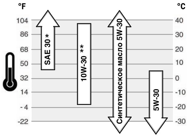
- IcnoIb3OBAHne Macna SAE 30 npn Tempeatypax HnKe 40^ (4^) npnbEeT K 3aTpynHeHHomy 3aIyCKy DInrataTeJ.
** IcnoIb3ObaHne Macna 10W-30 npI TeMnepaTpyax BblIe 80^ (27^) npBBeTeK noBbIeHNOMy nOTpe6JIeHIO Macna. YaIe npOBePraTe ypOBeHb Macna.
Kak npOBepntb ypoBHeb Macna/DoJnTb MacNo -Pnc. 2 4 Ipeed do6abJeHem nI npOBepkOy npOBHa Macla
- YctaHOBNTe DnIRatJIb B TROP3OHTaJIbHoe NONOKeHne.
OuHCTnTe 30Hy macIOn3aJIiNbHOro OTBepCTnO TJIIO6OrO Mycopa.
- Bbytaunte uyn nla n3mepenhy ypoBna macna (A) n o6oTpne ero chtoTprnnoKo (Pnc. 2).
PeKOMeHdaunnoNcNoJb3OBaHnIO TOnJIbBa
TOnnBO DoJXHO COOTBcTCTBOBaTcJeDyUoIIM Tpe6OBaHm:
- DahnBbI BnIraTeIb ceptnphiunpoBaH IJI pa60tblc dN3eJIbHbIM TOnIIIBOM. PnIN cNoJIb3OBAHm HEnpaBInbHorO TnIa TOnIIBa MoXET BO3HHKHTb CepHbI DIm, NOpEra MOUHOCTN INOBpeXdHeNE DBrIaTeJI, KOTOpBIE He 6yDyt NOKpbIbATcRaPAHTne.
- IcnoIb3yIte YnCTOe, CBExee DnI3eIbHOe TOJIINBO C UTeTAHOBbIM YNCLOM He MeHee 40. CBeexee TOJIINBO HE O6pa3yeT CMJONHCTbIX OTIOXeHm B TOJIINBHOr CNCTeMe. NOKynaiTe TOJIINBO B O6beMe, KOTOpby MOKeT 6bITb NCNoIb3OBAH B TeueHne 30 dHei. Cm. pa3dEn XpaHHeHne.
OCTOPOXHO: He nCnNoB3yTe KepocHn IINI 6eHN HBMcTo DN3eHbHO TOnNBA. HecO6JIaENHe 3TOr pEynpExeHn INPBeDeT K NOBpeJdeHIO DBIrTaTeN I aHHyIpOBaHnI rapaHTm Ha DBIrTaTeN.
Kak do6abntb TOnJnBO - Pnc. 5

OCTOPOXHO
ToTnIBO I ero napbI Ype3BbUaHIO orHeonacHbI N B3pbIBOONacHbI. BocnAmehene Hnn B3pbIB MOryT npNBecTN K CnJbHbIM OXORAM nn CmeptelbHomY nCXOy.
Pn do6ablen TOnJIbBa
- PπeJxIe Yem OTKpbItb KpbIbUky TOnJIbHOrO 6aKa, BbIKLIOUte DBrIaTeIb N daIte Emy OCTbITb B TeueHne, NO MeHSeM Mpe, 2 MmHT.
3aONHnIte TOJIINBbIb 6aOK, IIOHO HA OTKpblTom BO3dyXe, IIOBO Xopoio npOBetPnBaem0n 30He. - He donyckaTe nepenonHEnHa TOnJIbHOrO 6ka.3aONnHrTe 6ak npImepHo Ha 1,5doMa (38 MM) HIXe BepxHe KpOMKn rOpIOBnHbI, UTo6bl TOnJIbBO MOrIto pacuMPnTbC.
XpaHnTe TOnJIbMoB VdAnI OT NcKp,OTKpbITOrO PIIaMeHn,ROpeNOK, HArpeBaTeJbHbIX Pnp6OpOB INPPOuNX IcTOUHNKOB BOCPiJaMeHeHn.
Peynnpno npOBepnTe TOnnBONpOBoD,6ak, npO6ky nHHTnHnHa HnUne Tpeunn uYteek. Pn Heo6xOaMocTn, 3aMeHnTe Detan.
B cnyuae npoInBa tonnBa,doxndtebc ero noHoro nCnapenr,npexde yem 3anyctntb Dbratelb. - OuchTe KpbIbKy HAIINBHOI TOpIIOBInbI N 3OHy BOKpyr Hee OT IIO6oI rpr3n n OCTaTKOB MYcopa.CHIMNTE KpbIbKy TOIIINBO3anpABOCHoro NaTPy6ka (A, Pnc.5).
- 3aONHnTe TOJIINBbI b6ak (B) 6eHNOM. IJIa BO3MOxHOCtN pAcUmpenHa 6eHNHa, He 3aONHnTe BbIe HxHHe yactN rOpIOBnHb TOnJIINBHO 6aKa (C).
- YctahOBInTe Ha MeCTO KpbIuKy TOnPiBHorO 6aKa.
PekomeHdaunno nO nCnOJb3OBaHNIO OXnaJdaIoueJ XnDkoCTN
06bem oxnaaJdaIOuIe JxNIOKCTn (CM. pyKOBOCTBO I3rOBoTJIb OobpyoBaHn)
BHMAHne: 3TO DBVIRATEIb JxNIOKCTHO OXIAJDeHN.IIpaOxAKeHHn,
npEOITBpAaHEHn 6bpa3OBAHn pKaBHyI cMa3Kn BOJHORO HAcOcA Tpe6yETc
NCNoJIb3OBAHNe 50/50% CMeCN aHTNfPn3a, He CoepJaaEero foccpata, IN BODONPOBOHOI BObl.
PpOBepka/DoJIbBka oxlaJkaIoue JxNkoCTn

OCTOPOXHO
3To MoKet IpnBecTn K Cepbe3HbIM TeNIOBbIM OXOKrAm B pe3yIbTaTe Bbl6pOca napa nnI ropaye oxnaKaDaUoJe KxNkoCTn DbrgATEJ.

HE chImaIte KpbIuKy paIaNatOpa uNn EMcKoCTn, ecN nDbIrataTeIb rOpyuN npa60taT.
- Pénéd CHATNEM KpbIuKN paIaIATOPa IIN KpbIuKN paCauPiTeNBHO 6aKa n nepeD 3aMeHOn IIN DOJIaIBKOJ OXIAJDaIOSeJ XIKOCTN OCTaHOBITe DBIRaTeJB daIte EMY OCTbTb.
1. Pered 3Kcnnnyatauem npobepbTe ypOBeHb oxJaXdaIOUeJxNdkOCTn. UpOBeHb oxJaXdaIOUeJxNdkOCTn DOJIbMekJy OTMeTkAmn FULL n LOW/ADD Ha EMKoCTn oxJaXdaIOUeJxNdkOCTn. Ecm npOBeHb oxJaXdaIOUeJxNdkOCTn HN3Kn,doJIeTe B EMKoCT 50/50% CmEc oxJaXdaIOUeJxNdkOCTn COCTOJe N3 aHTINbp3A, he CoDEPkaaero foccpata, n BOONPOBOHOI BObl.
2.ДЯСНТИКрБИКи EMKOCTN NOCE OXNAJDEHURA DBINATEH NONOJKTTE TONCTYTO TKAHB Ha KpbIky EMKOCTN.ДЯСНТИМEDJIENHO NOBOPaHBAITE KpbIky POTIMTB HACOBOIT CTePENI.
3. EcniemKoCTb COBepseHNO ncta, Oobabte OXnaxKaIOuOyU KInKoCTb B emKoCTb IN paJnAtop.Cm.pyKOBoCDTO NO o6OpYDoBaHNIO nIa
MECTONOLOXeHnI,3KcNpIyatauIN N O6CnyKmbaHnE MKOCTN OXnaJdaIOUeJ KNUKOCTN paHaTopa.
4.ДЯСНТЯКршкп радиatorpo nOcne OxnaJdeHЯ DBIgATEЯ NONoJTe TOnCTyU TkaHь Na Kpbshky pardniatorpa.MdJIeHNO nobopaunBaIte Kpbshky paadniatorpo npOTb NacOBm CTpeJKN Do neBPOrO orpAnHHTeNJa.EcHn 3-NOd KpbshKy BByXoJNT nap noD abJeHMeN OToJDiTe, YTObI N36ExaTb TpaMbI. IocNe TOrO KAK BCE daBJIeHMe 6yEdt C6pOSeHNo HaxMTe Kpbshky paadniatorpo BHN3 IN NOBepHInTe eIe npOTb VacOBm CTpeJKe dIra ChTyrA.
Pn6opbI INHdkaTopbI
Ioka3aHHbIe np6Opby INHdkaTOpby ABNIAOTc TINHbIMn I NOka3bIBaIOT pa3NJHbIe BApnaHTbI, KOTOpbe MOrY INCNoB3OBaTbCra.ДЯ INHOPMaUmO paCNOJoxEHInФнKcIax np6Opob INHdkaTOpob ObaTNTecb K pykoBOdCTBy NO 3KcNlyatauIm.

Pnp6op temnepatypbO oxnaKaioe KndKoctN
IokaBbAeT TempeAtpy OXnaxDaIOSeJ XnIKOCTN, KOrda BbIKIOHaTeB 3JIeKTPoCnTEMbI 3aNyCz yCTaHOBJIe H bnoONKeHne BKNJ.
HopmaJIbHbI dHaIa3OH 80° -90°C (175° - 195° F)
OnacbI dnaa30n Bbiue 105^ (220^)

Pn6op KOJImYeCTBa Yacob pa6oTbI
ПокаыBaetсуммарhoeКолиесъчacobКспл�атудим.

Yka3aTeNb TOnJnBa
IokaBbAeT KOJIaHcEBo TOnIOBbA B ToONIOBHOM 6aKe.ДЯ CHINKHeH NOKOHDeBaEN DEKIXeTo TOnIOBbHbI K6a3aONIOHHeHbM.

HdkaTop temnepaotypb
CBeueHne HnDnkaTota TmepeatpybI CBnTeBteBCTByET O nepeRpeBE DnBaTaeJI. BbIKJouTe DnBaTaeN I npOBeBte UpoBeH oxNaXdauOe JxuKoctn (secm. pa3den InpOBeKAp OxnaXdaOooj XnuKoctn).
Y6eIntecb B03dya.x.
B OTCyTCTBnM Mycopa Ha paIaIaTope, IppeIaTCTbYIOJIeO IOTOKy

HdkaTop 3aXnraHna
PnpctyahOBBe bkyIIOHouateIe 3NKeTpUeCKO 3aNYcBa NIOLOXHEM BKLINHIMKATOp 3xKHHaHnD0JXeH cBtntbCnR. ppa6oTe DInrAteF
HnDnKATOp 3aXnRanH He nOJxEN CBETnTbC. EcnI npN yCTaHOBKe BbIKIOUATEJI 3eKnTPnuCheKOro zanycka B noLoXeHne BKJI HnDnKATOp He cBTntC, npOBepbTe npDeoxpAHntenB.

Инданкатор давлия macna DBurataЯ
Pn yctahOBBe kblIOUATEH 3neKtmuEeCKORe 3aIyCKa B NOLOXHEM E BKL INHkA TOp DabJeHNE MACBa D BuRATeNe DooJENG CEBNTBcT.Pn
paObe TbIraTeJI INHdNkaTOp DaJIbeHMa CnA B DbIraTeJI He DoJnxH CBETNbCBA. Ecn npa paObe TbIraTeJI HauJI CBeITNbCBA INHdNkaTOp DaJIbeHMa CnA, HEmeJeHHO BkJIIOUHTe DbIraTeJI. B NepByIO OHepeBb IpoBepbTe ypOBeHb Macna (cm. pa3JeN KaK npOBepBa/TdoJINaBb MaCNo). 3aTeM npOBepbTe 3JIeKtpueckyio CTcEMTA.

Hdukatop 3apAdkn
Ipy cyaTahOBke bkybIOAteyne3IeKTPmEeKOz3y aOnoKBa nOioXeHne BKLJnIHkATop 3apRdKa dnOxHKe CebITbcB. Pnp pa60e Tbeiratena
INHdkatop 3apJdkn He doJIkeh CBetntbC. Ecnin INHdkatop 3apJdkn NaHnaeT CBetntcb npi pa6ote DbrarTeJI, npOBepte 3neKtpueckyO cnCTemy.

HnDkaTOp HarpeBa HnHaKaJIbHaHn
KordaBbKJIIOUaTeNb 3aXIGaHnY yCTaHbNBAETC B NOJIOKeHne HArpeBa/HaKaIINBaHn IIN B NOJIOKeHne "BKn", INdIkaTOP HArpeBa
CBnTeJIbCTByET O NOOrpeBE KamepbI CROPaHNA CBeaHNAHaKaJINBaHNA.

HnkaTop TOnJIbHoroΦnIbTpα
HnDnKaTOp TOnnBHO pNtpa HauHaHaET CBeTbCra, KOrDa B TOnNBHOM pNtpe Co6npaTeC rNlWkOM MHO Bobl. HnDnKaTOp
dONJekn HORaCHyTB Nocle CmBa A3NIMKOB BObI n3 TOnNIBHORO fINbTpa. EcnI INdNKaTOP TOnNIBHORO fINbTpa 3arOpaeTc BO BpEma pa6oTb DnBraTeNa, BByIKIOuHTe DBMgATeNB nCneTBe BOy n3 TOnNIBHORO fINbTpa.
Kak 3anyctntb DvraTeIb-Pnc. 6

OCTOPOXHO
ToJIbIO n er npabI ype3BbIaHNo ORHeONaChbl B3pbIBOONaChbl.
BocnnaeHne Hn B3pbB MoryT npNBecTu K cnIbHbIM OXoRAM nIcMeptelbHomy NcxOy.
Pn3zanyckeDburatela
- Y6eIntecb,уTO rIyIuIteJIb,КрИшka TOnIIINBHorO 6aKa n B03dUshHbI ΦnIbTp HaxOДЯТСА CBОИX MecTAX n HAnEIXHO 3aKpeNJIeHbI.
B cnlyae nepenbBA tonnBa B kap6ipatope Dnirate, yctahOBnte Bo3dyuhyo 3acnoHky (ecmTAKOBAR NMeetc) B noLOXeHne open/run (OTKpbIra/paObaTa), a dpocceNHyO 3acNoHky B noLOXeHne fast (6bICtpo) n 3abOJnte DniratEn, noka OH He 3anYCTITcR.
Дя уBERHENHа copka cny6bl CTapTepa, IcnoIb3yIte KOpOTKHe CTaPTOBIE ZIKNJI, He npBbIaOuIe 15 cKeYHd B MmHyTu. IpoJOnKHTeJIbHbI 3aNyCK MoKETcNOPTnTB MOTOP CTapTepa.

OCTOPOXKHO

BbIOnHbIe ra3bl coDepeKaT Okncb yrIepoda - 6ecuBeTHbI n He MeIOU3n 3anaXa RoDBtBn ra3.
BdIxHne OKnc yrIepoJa (yrapHoro ra3a) MoKet Bbl3BaTb pBOTy, nOtePio CO3HaHn IIN CMEptb.
3anyckaIte n 3KcnpyaTpyIte DnBraTeIb BHe NOMEueHna.
He 3anyckaite DnirateIb NomeeHn IaKe np OTkpbItbIX Okhax IDBepx.
BHMHAHNE:ДанньдИгагелпocstabлentскOMmTaHnei Briggs & Stratton 6e3 macna.петед зунckOMдИгагелЯ,обзатelноЗалte MacLo cOrnaCHO nHTpykцIM hactoIe pykoBODCTBa.EcIn Bby 3anyctnte DBIratelb 6e3 macna, TO dIgatelb 6ydet HOBOCtahOBIMNo nobpeXdE,и 3TOT cnUaH He 6ydet nOKpbIbA TbCB rapaHTne.
OCTOPOXHO: PiepeIePbIbM 3aIyckOM dBIrTaTHe, 3aprIte AkkyMnyTOp B COOTBETCTBn C peKoHemDaIaIMy npoIb3DIOJIteN OOBpyODbAHn. HEBBIOJHHeN ETOFO YCIOBNI MOEt PnIBECTN KOBpEJDeHIO DBrTaTNe.
Примочанe: HeKOTOpbIe DnBraTeHIn n OobopydObaHne Cha6KeHbI oprahAmn dNCTaHcUHOHorO ynpabJIeHnA. KacateJIbHO paCNoJoxEHHn I pa6ToI orpAHO bNCTaHcUHOHorO ynpabJIeHnCMOTpIte pyKOBoDcTBO NO 3KcNpyTaUHN dNf KOHKPETHOrO OOBpyOboHnA.
BHIMAHHE: BCE KOMNHOENTbl, INCNOlb3yEmble dIra C6OpKn daHnOro DBrIaTeIa,doJXhbl OCTaBaTbCRA Ha CBOEM MecTe dIra ero HAnNeKaUe pa60tbl.
BHMMAHNE: IzrotOBHTeNB o6OpyIDoBAHnI, Ha KOTOPOM yCTaHOBNeH DBIRATeNB, ONpeJelAEt MAKCmAJbHyIO paOcHy CKOPoCTb DBIRATeNl. He donyckaTe nepeBbIeHNr 30TCKOPOCTn.
YCTPOICTBO DnA CHNXEHNRA TOKCNHOCHTN BbIXJONA
O6cIyKbAHne, 3aMeHa IINPpeMOHT yCTPOHCTB IN CNTTEM KOHTPOIA 3MCCN MOrYT BbIOJIHrTbCRA JIObO MaCTepCKo IINn CNEuaJInCTOM NO peMOHTY He
A B T O M O B H b bix D B r a t e n e J. O n d k o, I n d "6e c n n a t h o r o" 06cnyk u b h i N KOMIHOHTOB CNTeMbI NOHIXeHn TOKCHUOCTN BbIXNOTA, 3TN paB0Tb I OJXhbl BbIOHNHtBcRdJInePOM, CepTnФuINpOBAHbHbM 3aBODm-IMTOBOTeHem.CMOTPte rapaHTnHO Ha yCTPOiCtBO DnI CHIXeHn TOKCHUOCTN BbIXNOLA.

Ipeed BbINOJIHeHHe mpeyIINPOBOK nI pemOnTa:
- OToeHNHte OTPuataHbB BbIBoD aKKyMnTOpa (ToIbKO dIa DBnIraTeJe C 3JIeKTKpOCTApTePOM).
- IcnoIb3yIte TOLbKO IOxOJaIeN INCTpyMeNTbl.
He MeHnIte HacTPOkny npKnHbI, TAYINn INbIX DeTanepepyIaTopa dnyyBENuEHNAcTOTbI BpaueHnBA nDnRatEn.
3aNaChbIe qactn DOnJHbI 6bITb IeHTNHyIMn U yCTaHaBnBaTbcHa To Jx Ce Camoe MecTo, YTO INepBOHaayabHbIe DeTaJI. - He yadapnTe no maxobky MOJOTKOM nIN TBepdbIM npedMeTOM, T.K. maxobMKoJETno3Ke pa3OpBaTbCBO BpEma 3KcPnyatauIN DBiRatela.
Ta6nua BbINOJIHeHn TeXnueckoro O6cIyXnBaHn
Kaxdbie 8 yacob pa60tbI nIeXeJdHeBHO
- PpOBepka ypoBHa MaCna BDbnTaTeNe
- PpOBeBpTe yPoBeHb OXlaJkaIOUe JnIKoCTn
IpeBbIe 50 yacob (nepboHaayabHna npupa6oTKa)
3aMeHnTeMacNoBDbVrataTeIe*
Yepe3 kaxkbie 100 yacob pa6oTbi
- Поверпту haтжени peMHBAHTNITOPa
- Почисту радиатор
- PoiuCTnTe BOZdyuHbI ΦnIbTp
- PpOBepbTe rIywnTeJIb n noOuNCTnTe NCKporacnteJIb (ecJn yCTaHOBJIeH)
Yepe3 kaxkbie 150 cacob pa6oTbI
3aemeHte macNo B Dnuratene
3aMeHHTeMaCLHaBHyΦnJbTp
Kaxdbie 600 yacob pa6oTbI nn exeroqdo
3aMeHa BOZdyuHOro QnJIbItpa
- Поверп Te 3a3op KlaanaHa ■
3aMeHHTe TOJIINBHybI QnIbTp A
Yepe3 kaxdbie 1500 yacob pa60tbI
- PpOeBpeΦopCyHKn BnPbIcKa
ExeroDnO
3aMeHInTeMacNoBDbVraTeIe*
3aMeHHTeMaCLHaBHyΦnJbTp
3aMeHnTe OXlaJdaHOuYU XnIKOCTb
- Поверп te haTЯженье pemнь BeHTnJIrToPA
- Почисту радиатор
- Поверьтейлuyштели почсптейнckрогацтел (ecn yctahOBneH)
3aMeHa Bo3dyuHoro fNtpa
3aMeHnTe TOIINBHybI qNJIbTp
- Поверпге заор Клanaна -
- 06cnykBaIte DnBraTeJIb YaIe npi pa6Ote C 6oJIbShIMN Harpy3kAMN IIN B yCIOBIAx BbICOKNX TempeAtyp.
CobnoaTe rpaFmK 06cnykBaHnI n3rOToBnTeJI npI nCNoIb3OBaHnI DeTaJIe, n3rOToBHeHHx He KOMNaHnei Briggs & Stratton.
06CnyxNBAHnE DOJnxHO BbIOnHrTcRa ABTopu3OBAHHbIM DInpePOM DENSO.
He tpe6yetcnaKa He 6ydyT 3aemeHb np6bnmb pa6oTb Dniratela.
PpOBepKa rIyUnTeTn n NCKpoynobuTeTn

OCTOPOXHO

Bo BpempaobtIbBnraTeIN BbIeJIaOT TEnIO. DeTANI dBnraTeJI, BOcObeHNOCTIgUwntEn, cTaHOBArTc OueHb rOpAIMN.
XpaHnTe 60pOyDOBaHne Ha paccToHmN OT KOtIOB,NeChE,BOoHOHaPeBaTeIeN I npOvHX npIbOpOB, B KOTOpBX mCNoJIb3yOTc ROpeIKN mN HIIbe NCTOCHNI BOCINNAmeHEHnI, NCKOJbKY OHN MOrYT BOCINNAmeHnTb Napbl TOPINBA.
Motophoe macno
3aMeHnTe MOTOPHOe MaCNo, KOrDa DvBraTeNb eUe TeNJIbI.
YcTaPaHeHne HEmCnpaBHOCTe
HyjdaetebcBcoeICTbIn?3auiTeHa web-caT BRIGGSandSTRATTON.COM nIIN NO3BOHNTe 1-800-233-3723.
TexHnueckne daHHbIe
TexHnueckne daHbIe no DnurTaTeJIIO
JIuHoeI KOMMepueckoe IcNoJIb3ObaHne
2 roda
3 roda
2 roda
* Otmte cneu nie nea hie npnabhe npaHTnB: PAMKax daHoro rapaHTnHO rnoica deTALN B BYIOJIHe na paoBt rapaHTpyETcB TceHne 2 net. TaPANTHa HOCOBHe Detan HnpDeBaTeCn HpTeTn Ro3KcIpyataum. RapantHa HCObHBle detan NOKpbBAeT, HO He ORAPAHNAeTcH IN HE ICKNIoAe6bok CUNINHPOB, ROJBOk6boka CUNINHPOB, KOJIeHATb BAN, paCppeJeHInTEbHb BAn, NOPHI, TOIKAteLIM, MAXOBIK, KOPyuc maxOBiKA, MACIAHb HAcOC, BEHTNIATpO, SKKNbI, MEXAHcEckN peryIATpO, BNYCKHO KOLKeTbP, NOdON KapTepa. TaPANTHa HocOBHbe Detan He NOKpbBAeT H e ORAPAHNAeTcH KOJIbCaMn NOpIHNe, ZAMEHEmbIM NODUHNHKAMs, BOJHbIM HAcOCOM, IIObIM 3JIeKTOObOpYDoBAHmE, KOMIOHENTAmn PnIBOda KlanahanOB, YNJOTHEHmM, PpOKNaJdAMn, KAp6Opatopamn, BByNUCKHbIM KOLNEKTOPOM, NATpy6kAMn, BCEMN KOMIOHENTAMN TOPINBHOICCTEmbI, FOpCYHKAMn, INHXEKTOpHbIM HACOCOM, Ty60KOMPecCCOpM, rnyuHTeMeM, IIObIM fMbTPAMn, PAIDATOPom, TepMOCTaTOM, CBeAMn 3aXJrAHHaRn, CBeAMn HAKAJINBAHm, HAcOCAMn NODKaChN ToTIINBa. RaPANTHbI PeNoD A HauNHAeTC S dAtb IOKyIKN PEPBbIM PO3NHyHM NOKyPATAmE IN KOHeYhBM KOMMepeCEKMn INZ3OBaTeEM and 3aKaHUYBaTeCn No IcTeHeHm NepNoDA BVPemEnu, yka3aHHO B pInBEdeHHo BVlle TeTablne.
IJa 10
B OTHOseHn BaSei rapaHTnn
Kopnpaun "B&S" c roTOBHOCTbIO npOn3BOUIT rapaHTnHbI peMOHT n npINOCHT
3NBHeHNe 3a npUnHHeHNoB BAM 6ecNOKOCTBO. IpObeDeHne rapaHTnHOro pEmoHTa
pa3peWHeNo IIObOMy YpONHomOeHHOMC CepBcHNOHcy DInepy Briggs & Stratton 3/LC.
B 60bluHNCTBe clyuaeB rapaHTnHbI peMOHT npOn3BOUITc8 bICtPO n B 6ecCnOpHOM
nopJKe. Ondako IHORa Tpe6oBaHnA h rapaHTnHoe 6cnyXnbAHne He ABnIoTcR
onPabDaHNbIMn. HApnpMep, rapaHTn He paCNPocTpaNHTcRA He Tc Lyuayn, KOrda
deFeKTb IBVaTeArel ABmLncpe3yNbTaTOM eHnpaBnHOro NcOpJIb3OBaHnA,
OTcYCTbNHaNDexKaUeO6cLyXbAHnA INN KOrDa NOBpeXdHeNPAO3oUln B
npOecce TpaHCnOpTnpOBKn, norpy3OCHo-pa3rpy3OHybIX pa6Ot, CKJaDnPoBaHnA
DbIratTeNe INI IN3-3a INx HnpaBnHbOH yctAHOBKn. FapAHTn TaKke aHNyUnpyeTcR,
ecNbI ydAnEe HcpNbHbI HOpem DBiratTeJI INI EIN cNn DBratTeJI bIbnBDOn3MeHEH
Inl moNfNiproBaH.
- General Information
- Date of purchase:
- Engine model:
- Engine Power Rating Information
- Operator Safety
- SAFETY AND CONTROL SYMBOLS
- WARNING
- When Adding Fuel
- When Starting Engine
- When Operating Equipment
- When Changing Oil
- When Transporting Equipment
- When Storing Gasoline Or Equipment With Fuel In Tank
- RNING
- Before performing adjustments or repairs:
- When testing for spark:
- Features and Controls
- Operation
- Oil Recommendations
- How To Check/Add Oil - Figure ② ④
- Before adding or checking the oil
- Oil Pressure
- Fuel Recommendations
- Fuel must meet these requirements:
- How To Add Fuel - Figure ⑤
- Coolant Recommendations
- How To Check/Add Coolant
- Gauges And Lights
- Coolant Temperature Gauge
- Hour Meter Gauge
- Fuel Gauge
- Temperature Light
- Ignition Light
- Engine Oil Pressure Light
- Charge Light
- Heat or Glow Light
- Fuel Filter Light
- How To Start The Engine - Figure 6
- How To Stop The Engine - Figure
- Maintenance
- Emissions Control
- Maintenance Chart
- Every 8 Hours or Daily
- First 50 Hours (initial Break-In)
- Every 100 Hours
- Every 150 Hours
- Every 600 Hours or Annually
- Every 1500 Hours
- Annually
- Inspect Muffler And Spark Arrester
- How To Check Coolant
- How To Change The Oil - Figure ② ③
- Remove Oil
- Change The Oil Filter
- Add Oil
- How To Service The Air Filter - Figure 7
- Replace fuel filter
- Drain water from fuel filter
- How To Check/Adjust The Fan Belt - Figure 9
- Check Fan Belt
- Adjust Fan Belt Tension
- Storage
- When Storing Fuel Or Equipment With Fuel In Tank
- Engine Oil
- Troubleshooting
- Specifications
- LIMITED WARRANTY
- OUR PRODUCT
- Warranty Period
- Vanguard™ 3/LC
- Major Parts Warranty *
- Parts & Labor *
- About Your Warranty
- Briggs & Stratton Corporation (B&S), the California Air Resources Board (CARB) and the United States Environmental Protection Agency (U.S. EPA) Emission Control System Warranty Statement (Owner's Warranty Rights and Obligations)
- California and United States Emission Control Warranty Statement
- Briggs & Stratton Emission Control Warranty Coverage
- Owner's Warranty Responsibilities
- Briggs & Stratton Corporation Emission Control Warranty Provisions
- Warranted Parts
- Osha nHΦopMaun
- Data Ha KynyBaHe:
- Moden ha Dbratela:
- HOpMaIg 3a HOMHaIHaT a MoUHOCT Ha DBVaTeJIte
- Texhika 3a 6e3oNaChOCT Ha onepaTopa
- CIMBOJIN 3A BE3ONACHOCT IN YYPABJIEHNE
- PNEyPPEKDEHNE
- PPEyPEXEHENE
- PpI dOJImbaHe Ha rOpNB0
- PnCstaptnpaHn DnBnatae
- Ppi pa6oTea MaunHa
- Pn CmehBaHe Ha MacNo
- Ptp TaHcnpOpTnpaHe Ha MaunHaTa
- Korato ckaiaipate 6eH3n Hn o6OpyDahe c roPbO B pe3epBoapa
- PNEyPEXKDEHNE
- PNEUYNPEXKDEHNE
- Ipeu n3Bpwahe ha peryunpoBkn nonpaBkn:
- PnH3npo6BaHe 3a nckpa:
- Elenentny uypablenia
- Pa6ota
- Пpenopьки 3a MacJIoTO
- Kak ce npoBepBa/HaIbBa MacNo -ФИгура 2 4
- IpeiHaIBaHe IINI npOBepBaHe Ha MacJIoTO
- HaJrahe Ha MacJoto
- Ppenopbkn 3a ronpBOTO
- TopNBTO Tp6Ba Da otROBapHa cJIeHNHe N3NCKBAHn:
- Kak ce HajiBa Macno - Fmrypa ⑤
- TropBOTO NHEROBITE napn ca n3KJIIOHHTeINHO ORHEONACHN N36yXJIINB.
- Ppi DJIINBaHe Ha rOpNBo
- Ppenopbkn 3a oxlaekdaeta Teuhoct
- Kak ce npOBepraBa/haJIbBa oxJaXDaIaTa TeuHOCT
- Morat da ce noIyut cepno3Hn 3rnapnO tOCbo6kdaBaaata ce napa nn ot ropeuata oxlaackdaa TeHocT.
- I3mepBaTeJIHn ypeDN i CBETJIINHHN INHdNKaTOPN
- TepMometbpo 3a oxJaKaDaaTa TeuHOCT
- Yacobn6poa
- I3mepBaTeJEn ypeed 3a HaJIuHOrROPBO
- CBeTInHeH INHdNkaTop 3a TemnepaTypa
- CBeTJIHHeH INDnKaTOP 3a 3anaJIbAHe
- CBeTtHnEH nHnKaKOp 3a ha MacNToB bDnRaTeIe Korato KOHTAKTHNAT KIOUe hA no3nZm4 ON (BKn.), CBeTtHnHHnT HnHnKaKOp 3a HnAHaTHeTO hA macNTo TpRb6A da CBtN. IOM
- CBeTJInHeH INHnKAtOp 3a 3apeXdaHe
- CnHaJIHa JAmNa 3a HarpeBHa CBeu
- CBeTInHeH INdkaTop 3a fNtBpa 3a rOpNBO
- Kak ce cnapa Dnrgatele - Fnrpa 6
- PnCTaptnpaHneHaDbiratena
- Kak da cnpete DnurateJna - Fmrgpa 6
- TexHnuecko obcnykBahe
- KoHTpOHa eMnCnIte
- PPEyIPEXDEHNE
- Ipeu n3BbPbBaHe ha peryunpOBKn nonpaBKn:
- CmHa Ha MacJIeHnФJITbP
- HaHnBaHe Ha MacJo
- Kak da ce o6cnykBa Bb3duhnaФnltbp-Фnrgpa 7
- KaK ce cMeHЯФиNTbpa 3a ropnBO -ФИrgya 8
- CmeHete nIbpa 3a rOpBOTO
- I3toe Boata ot hnltbpa 3a ropnboto
- Kak ce npOBepBa/peryInpa pembka Ha
- BeHTnlaTopa -FHyrpa 9
- Поберразе на ремьka на BeHTnilatopa
- Perynipahe Ha onbbaHeTo Ha pembKa Ha BEHTnlaTopa
- CknaipaHe
- PnCknaDnpaHe Ha ropBO nIHa MaunHa c ropBO B pe3epBoapa
- MacnotoHaDnrgateTna
- OTKpNbAHe n OTCTpaHbAbe Ha Hen3npaBHOCTM
- Двигаел Vanguard™ 3/LC
- Гаранцяз ocHOBnЧа'tN\*
- Pe3epBnH qactn n Bnlaran Tpyd
- OTHOCHO Baaata rapaHnra
- Vseobecné informace
- Pries jjungiant varikli
- OCTOPOXKHO
- OCTOPOXHO
- Ipeep BbINOJIHHeHEm peryIINpOBOK nIpeMOHTa:
- Pn npOBepKe cnCTembl 3aXmraHn:
- y3nbI dBnraTeJI n opraHbI ynpabJeHna
- 3Kcnpnyataza
- PeKOMeHndaцnnoNcNoJIb3OBaHHIO MacJa
- Kak npOBepntb ypoBHeb Macna/DoJnTb MacNo -Pnc. 2 4 Ipeed do6abJeHem nI npOBepkOy npOBHa Macla
- PeKOMeHdaunnoNcNoJb3OBaHnIO TOnJIbBa
- TOnnBO DoJXHO COOTBcTCTBOBaTcJeDyUoIIM Tpe6OBaHm:
- Kak do6abntb TOnJnBO - Pnc. 5
- Pn do6ablen TOnJIbBa
- PekomeHdaunno nO nCnOJb3OBaHNIO OXnaJdaIoueJ XnDkoCTN
- PpOBepka/DoJIbBka oxlaJkaIoue JxNkoCTn
- Pn6opbI INHdkaTopbI
- Pnp6op temnepatypbO oxnaKaioe KndKoctN
- Pn6op KOJImYeCTBa Yacob pa6oTbI
- Yka3aTeNb TOnJnBa
- HdkaTop temnepaotypb
- HdkaTop 3aXnraHna
- Инданкатор давлия macna DBurataЯ
- Hdukatop 3apAdkn
- HnDkaTOp HarpeBa HnHaKaJIbHaHn
- HnkaTop TOnJIbHoroΦnIbTpα
- Kak 3anyctntb DvraTeIb-Pnc. 6
- Pn3zanyckeDburatela
- YCTPOICTBO DnA CHNXEHNRA TOKCNHOCHTN BbIXJONA
- Ipeed BbINOJIHeHHe mpeyIINPOBOK nI pemOnTa:
- Ta6nua BbINOJIHeHn TeXnueckoro O6cIyXnBaHn
- Kaxdbie 8 yacob pa60tbI nIeXeJdHeBHO
- IpeBbIe 50 yacob (nepboHaayabHna npupa6oTKa)
- Yepe3 kaxkbie 100 yacob pa6oTbi
- Yepe3 kaxkbie 150 cacob pa6oTbI
- Kaxdbie 600 yacob pa6oTbI nn exeroqdo
- Yepe3 kaxdbie 1500 yacob pa60tbI
- ExeroDnO
- PpOBepKa rIyUnTeTn n NCKpoynobuTeTn
- Motophoe macno
- YcTaPaHeHne HEmCnpaBHOCTe
- TexHnueckne daHHbIe
- B OTHOseHn BaSei rapaHTnn
Brand : BRIGGS & STRATTON
Model : BRIGGS & STRATTON 585447
Category : Gasoline engine