9227CB - Polisher MAKITA - Free user manual and instructions
Find the device manual for free 9227CB MAKITA in PDF.

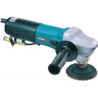
| Product Type | Polisher / Sander |
| Brand | Makita |
| Model | 9227CB |
| No Load Speed | 0 - 3,000 min⁻¹ |
| Variable Speed | 600 - 3,000 min⁻¹ (6 positions) |
| Max. Wool Pad Capacity | 180 mm |
| Max. Abrasive Disc Capacity | 180 mm |
| Overall Length | 470 mm |
| Net Weight | 3.0 kg |
| Power Supply | Single-phase mains, double insulation (no ground) |
| Shaft Lock | Yes |
| Bow Handle | Removable, adjustable in 2 directions |
| Continuous Operation | Yes (lock button) |
| Trigger | Progressive |
| Backing Plate | Included (for wool pad) |
| Included Accessories | Wool pad, sleeve 18, hex wrench, pin wrench |
| Sound Pressure Level | 81 dB(A) |
| Max Noise Level | 85 dB(A) |
| Vibration (acceleration) | 4 m/s² |
| Brush Replacement | By wear mark |
| Maintenance | By Makita service center |
Frequently Asked Questions - 9227CB MAKITA
User questions about 9227CB MAKITA
0 question about this device. Answer the ones you know or ask your own.
Ask a new question about this device
Download the instructions for your Polisher in PDF format for free! Find your manual 9227CB - MAKITA and take your electronic device back in hand. On this page are published all the documents necessary for the use of your device. 9227CB by MAKITA.
USER MANUAL 9227CB MAKITA
The following show the symbols used for the tool. Be sure that you understand their meaning before use.
Symboles
Read instruction manual.
Wear safety glasses.
1 Protrusion of loop handle
2 Matching hole in gear housing
3 Shaft lock
4 Loop handle
5 Bolts
6 Hex wrench
7 Wool pad
8 Sleeve 18
9 Backing pad
10 Spindle
11 Press
12 Switch trigger
13 Lock button
14 Speed adjusting dial
15 Lock nut
16 Abrasive disc
17 Rubber pad
18 Lock nut wrench
19 Loosen
20 Tighten
21 Limit mark
22 Screwdriver
23 Brush holder cap
SPECIFICATIONS
Model 9227CB
Max. capacities (dia.)
Wool pad 180 mm
Abrasive disc 180 mm
No load speed (^-1) 0-3,000
Overall length 470 mm
Net weight 3.0 kg
- Due to our continuing program of research and development, the specifications herein are subject to change without notice.
Note: Specifications may differ from country to country.
Power supply
The tool should be connected only to a power supply of the same voltage as indicated on the nameplate, and can only be operated on single-phase AC supply. They are double-insulated in accordance with European Standard and can, therefore, also be used from sockets without earth wire.
Safety hints
For your own safety, please refer to the enclosed safety instructions.
ADDITIONAL SAFETY RULES
ENB047-3
- Always use eye and ear protection. Other personal protective equipment such as dust mask, gloves, helmet and apron should be worn when necessary. If in doubt, wear the protective equipment.
- Always be sure that the tool is switched off and unplugged before carrying out any work on the tool.
- Accessories must be rated for at least the speed recommended on the tool warning label. Wheels and other accessories running over rated speed can fly apart and cause injury.
- Check the backing pad carefully for cracks, damage or deformity before operation. Replace cracked, damaged or deformed pad immediately.
- Check that the workpiece is properly supported.
- Hold the tool firmly.
- Keep hands away from rotating parts.
-
Make sure abrasive disc or wool bonnet is not contacting the workpiece before the switch is turned on.
-
When sanding metal surfaces, watch out for flying sparks. Hold the tool so that sparks fly away from you and other persons or flammable materials.
- Do not leave the tool running. Operate the tool only when hand-held.
- Pay attention that the wheel continues to rotate after the tool is switched off.
- Do not touch the workpiece immediately after operation; it may be extremely hot and could burn your skin.
- If working place is extremely hot and humid, or badly polluted by conductive dust, use a short-circuit breaker (30 mA) to assure operator safety.
- Do not use the tool on any materials containing asbestos.
- Do not use water or grinding lubricant.
- Ventilate your work area adequately when you perform sanding operations.
- Always use the correct dust mask/respirator for the material and application you are working with.
- Ensure that ventilation openings are kept clear when working in dusty conditions. If it should become necessary to clear dust, first disconnect the tool from the main supply (use non metallic objects) and avoid damaging internal parts.
SAVE THESE INSTRUCTIONS.
OPERATING INSTRUCTIONS
Installing loop handle
Important:
Always be sure that the tool is switched off and unplugged before installing the loop handle.
Always install the loop handle on the tool before operation. Hold the tool's switch handle and the loop handle firmly with both hands during operation.
Install the loop handle so that its protrusion will fit into the matching hole in the gear housing. (Fig. 1)
Install the bolts and tighten them with the hex wrench. The loop handle can be installed in two different directions as shown in Fig. 2 & 3, whichever is convenient for your work. (Fig. 2 & 3)
Shaft lock (Fig. 4)
Press the shaft lock to prevent spindle rotation when installing or removing accessories such as wool pads.
CAUTION:
Never actuate the shaft lock when the spindle is moving. The tool may be damaged.
Installing or removing wool pad (Fig. 1 & 5)
Important:
Always be sure that the tool is switched off and unplugged before installing or removing the wool pad.
To install the wool pad, first remove all dirt or foreign matter from the backing pad. Press the shaft lock and screw the backing pad onto the spindle. Insert the sleeve 18 into the center hole of the backing pad. Using the sleeve 18 as a positioning guide, install the wool pad on the backing pad with the sleeve 18 inserted through the center hole of the wool pad. Then remove the sleeve 18 from the backing pad. To remove the wool pad, just tear it off the backing pad. Then unscrew the backing pad while pressing the shaft lock.
Switch action (Fig. 6)
CAUTION:
Before plugging in the tool, always check to see that the switch trigger actuates properly and returns to the "OFF" position when released.
To start the tool, simply pull the trigger. Tool speed is increased by increasing pressure on the trigger. Release the trigger to stop. For continuous operation, pull the trigger and then push in the lock button. To stop the tool from the locked position, pull the trigger fully, then release it.
Speed adjusting dial (Fig. 7)
The tool speed can be infinitely adjusted between 600 rpm and 3,000 rpm (rpm at the time when the switch trigger is fully pulled) by turning the speed adjusting dial to a given number setting from 1 to 6. Higher speed is obtained when the dial is turned in the direction of number 6; lower speed is obtained when it is turned in the direction of number 1. Refer to the table below for the relationship between the number settings on the dial and the approximate tool speed.
| Number | RPM (min-1) |
| 1 – 2 | 600 – 900 |
| 2 – 3 | 900 – 1,500 |
| 3 – 4 | 1,500 – 2,100 |
| 4 – 5 | 2,100 – 2,700 |
| 5 – 6 | 2,700 – 3,000 |
CAUTION:
- If the tool is operated continuously at low speeds for a long time, the motor will get overloaded and heated up.
- The speed adjusting dial can be turned only as far as 6 and back to 1. Do not force it past 6 or 1, or the speed adjusting function may no longer work.
Polishing operation (Fig. 8)
CAUTION:
Always wear safety glasses or a face shield during operation.
Pull the trigger and turn the speed adjusting dial until you obtain the appropriate speed for your work. When polishing, keep the wool pad at an angle of about 15^ to the workpiece surface.
FOR USE AS A SANDER
Installing or removing abrasive disc (Fig. 1, 9 & 10)
Important:
Always be sure that the tool is switched off and unplugged before installing or removing the abrasive disc.
Mount the rubber pad onto the spindle. Fit the abrasive disc on over the rubber pad and screw the lock nut onto the spindle. Press the shaft lock and tighten the lock nut using the lock nut wrench. To remove the abrasive disc, follow the installation procedure in reverse.
NOTE:
The rubber pad, abrasive disc, lock nut and lock nut wrench are optional accessories.
Sanding operation (Fig. 11)
CAUTION:
Always wear safety glasses or a face shield during operation.
Keep the abrasive disc at an angle of about 15^ to the workpiece surface.
MAINTENANCE
CAUTION:
Always be sure that the tool is switched off and unplugged before carrying out any work on the tool.
Replacement of carbon brushes (Fig. 12 & 13)
Replace carbon brushes when they are worn down to the limit mark. Both identical carbon brushes should be replaced at the same time.
To maintain product safety and reliability, repairs, maintenance or adjustment should be carried out by a Makita Authorized Service Center.
18 Stirnlochschlüssel
These accessories or attachments are recommended for use with your Makita tool specified in this manual. The use of any other accessories or attachments might present a risk of injury to persons. The accessories or attachments should be used only in the proper and intended manner.
F ACCESSOIRES
ATTENTION :
EC-DECLARATION OF CONFORMITY
The undersigned, Yasuhiko Kanzaki, authorized by Makita Corporation, 3-11-8 Sumiyoshi-Cho, Anjo, Aichi 446-8502 Japan declares that this product
(Serial No.: series production)
manufactured by Makita Corporation in Japan is in compliance with the following standards or standardized documents,
HD400, EN50144, EN55014, EN61000
in accordance with Council Directives, 73/23/EEC, 89/336/EEC and 98/37/EC.
FRANÇAISE
DECLARATION DE CONFORMITE CE
HD400, EN50144, EN55014, EN61000.
ITALIANO
Michigan Drive, Tongwell, Milton Keynes,
Bucks MK15 8JD, ENGLAND
PORTUGUES
DECLARATION DE CONFORMIDADE DA CE
O abaixoassinado, Yasuhiko Kanzaki, autorizzato pada Makita Corporation, 3-11-8 Sumiyoshi-Cho, Anjo, Aichi 446-8502 Japan,告诉她 que este produits
EU-DEKLARATION OM KONFORMITET
Undertegnede, Yasuhiko Kanzaki, med fuldmagt fra Makita Corporation, 3-11-8 Sumiyoshi-Cho, Anjo, Aichi 446-8502 Japan, erkræer hermed, at dette produit
Michigan Drive, Tongwell, Milton Keynes,
Bucks MK15 8JD, ENGLAND
ENGLISH
Noise And Vibration
The typical A-weighted sound pressure level is 81 dB (A).
The noise level under working may exceed 85 dB (A).
- Wear ear protection. -
The typical weighted root mean square acceleration value is 4m / s^2