
6305W - Electric drill MAKITA - Free user manual and instructions
Find the device manual for free 6305W MAKITA in PDF.
Download the instructions for your Electric drill in PDF format for free! Find your manual 6305W - MAKITA and take your electronic device back in hand. On this page are published all the documents necessary for the use of your device. 6305W by MAKITA.
USER MANUAL 6305W MAKITA
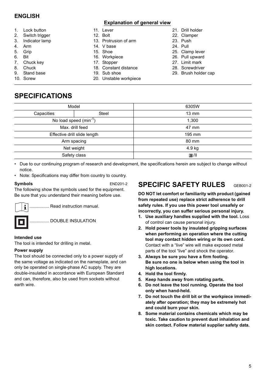
ENGLISH Explanation of general view
Lock button Switch trigger Indicator lamp Arm Grip Bit Chuck key Chuck Stand base Screw Lever Bolt Protrusion of arm V base Shoe Workpiece Stopper Constant distance Sub shoe Unstable workpiece
- Due to our continuing program of research and development, the specifications herein are subject to change without notice.
- Note: Specifications may differ from country to country. END201-2 Symbols The following show the symbols used for the equipment. Be sure that you understand their meaning before use. ................ Read instruction manual. ................ DOUBLE INSULATION Intended use The tool is intended for drilling in metal. Power supply The tool should be connected only to a power supply of the same voltage as indicated on the nameplate, and can only be operated on single-phase AC supply. They are double-insulated in accordance with European Standard and can, therefore, also be used from sockets without earth wire.
SPECIFIC SAFETY RULES
GEB001-2 DO NOT let comfort or familiarity with product (gained from repeated use) replace strict adherence to drill safety rules. If you use this power tool unsafely or incorrectly, you can suffer serious personal injury.
1. Use auxiliary handles supplied with the tool. Loss
of control can cause personal injury.
2. Hold power tools by insulated gripping surfaces
when performing an operation where the cutting tool may contact hidden wiring or its own cord. Contact with a “live” wire will make exposed metal parts of the tool “live” and shock the operator.
3. Always be sure you have a firm footing.
Be sure no one is below when using the tool in high locations.
4. Hold the tool firmly.
5. Keep hands away from rotating parts.
6. Do not leave the tool running. Operate the tool
only when hand-held.
7. Do not touch the drill bit or the workpiece immediately after operation; they may be extremely hot
and could burn your skin.
8. Some material contains chemicals which may be
toxic. Take caution to prevent dust inhalation and skin contact. Follow material supplier safety data.
SAVE THESE INSTRUCTIONS
MISUSE or failure to follow the safety rules stated in this instruction manual may cause serious personal injury. CAUTION:
- Raise the drill fully when installing the drill stand. FUNCTIONAL DESCRIPTION Remove the secured stand base from the steel carrying case and fix it on the shoe with two screws. (Fig. 5) CAUTION:
- Always be sure that the tool is switched off and unplugged before adjusting or checking function on the tool. CAUTION:
- Remove the grip from the tool when using with the drill stand. Switch action (Fig. 1) CAUTION:
- Before plugging in the tool, always check to see that the switch trigger actuates properly and returns to the “OFF” position when released. To start the tool, simply pull the switch trigger. Release the switch trigger to stop. For continuous operation, pull the switch trigger and then push in the lock button. To stop the tool from the locked position, pull the switch trigger fully, then release it. Indicator lamp (Fig. 2) The green power-ON indicator lamp lights up when the tool is plugged to the mains. If the indicator lamp is lit but the tool does not start even if the tool is switched ON, the carbon brushes may be worn out, or the motor or the switch may be defective. If the indicator lamp does not light up, the mains cord or the indicator lamp may be defective. When the mains cord is defective, the tool neither starts nor lights the indicator lamp. When the indicator lamp is defective, the tool starts without the indicator lamp lighting up. ASSEMBLY CAUTION:
- Always be sure that the tool is switched off and unplugged before carrying out any work on the tool. Installing grip (Fig. 3) Install the grip securely on the arm provided in a box with the tool. Installing or removing drill bit (Fig. 4) To install the bit, place it in the chuck as far as it will go. Tighten the chuck by hand. Place the chuck key in each of the three holes and tighten clockwise. Be sure to tighten all three chuck holes evenly. To remove the bit, turn the chuck key counterclockwise in just one hole, then loosen the chuck by hand. After using the chuck key, be sure to return to the original position.
Stand base - - - screw M6 x 14 to be used Lever - - - bolt M6 x 10 to be used To install the lever on the arm, use two holes in the lever. Fit the hole in the top of the lever to the protrusion of arm and secure it with the bolt in another hole. Secure the tool to the table or stable and level surface. (Fig. 6) Secure and lock the workpiece to avoid its rotation using spindled holes provided in the base. (Fig. 7) V base - - - Screw M6 x 16 to be used (Fig. 8 & 9) V base allows a drill bit to be held perpendicular to workpiece when drilling the workpiece with round section such as steel pipe and the like. Secure V base with screw provided in a box with the tool. Stopper - - - screw M 5 x 16 and washer 5 to be used (Fig. 10 & 11) The stopper allows operator to drill a hole with the constant distance away from the workpiece end. Secure the stopper with screw and washer provided in a box with the tool. Sub shoe - - - screw M 6 x 16 to be used (Fig. 12 - 14) Use the sub shoe when the workpiece is unstable as shown in the figures. Secure the sub shoe on the shoe with screws (2 pcs.) provided in a box with the tool. OPERATION Positioning the clamper Determine the clamper position considering the position of the drill bit tip and the shoe according to the thickness of workpiece. To change the position of the clamper, first push or pull the clamping lever and then move the lever to the desired position. After changing, return the clamping lever to the original position. (Fig. 15) CAUTION:
- When changing the position of the clamper, be sure to hold the arm before operating the clamping lever. With the arm held, push or pull the clamping lever so that the arm does not unintentionally move. NOTE:
- After the clamper is secured, the maximum travel of the drill holder is 47 mm by pulling the grip upward. (Fig. 16) Positioning the drilling hole (Fig. 17) Mark a sign lightly as a position of drilling a hole into the workpiece by placing the drill bit tip on the surface of workpiece so that it is located between the drill bit and the shoe. If you need any assistance for more details regarding these accessories, ask your local Makita Service Center.
Drill bits Chuck key Grip assembly Borer attachment Lever Stand base CAUTION:
- At this time, place the workpiece so that the shoe contacts as great part of surface of the workpiece as possible. Drilling operation This tool is intended for drilling in metal. Apply machine oil when drilling. After determining the position of a hole, turn on the tool and start drilling by pulling the grip upward. CAUTION:
- Press the grip lightly and softly so that the number of drill bit rotation is not lessened.
- Hold the tool firmly so that the drill bit is perpendicular to the workpiece.
- There is a tremendous twisting force exerted on the tool/bit at the time of hole breakthrough. Reduce your force applied on the grip by pulling it more lightly and exert care when the bit begins to break through the workpiece. MAINTENANCE CAUTION:
- Always be sure that the tool is switched off and unplugged before attempting to perform inspection or maintenance. Replacing carbon brushes Remove and check the carbon brushes regularly. Replace when they wear down to the limit mark. Keep the carbon brushes clean and free to slip in the holders. Both carbon brushes should be replaced at the same time. Use only identical carbon brushes. (Fig. 18) Use a screwdriver to remove the brush holder caps. Take out the worn carbon brushes, insert the new ones and secure the brush holder caps. (Fig. 19) To maintain product SAFETY and RELIABILITY, repairs, any other maintenance or adjustment should be performed by Makita Authorized Service Centers, always using Makita replacement parts. ACCESSORIES CAUTION:
- These accessories or attachments are recommended for use with your Makita tool specified in this manual. The use of any other accessories or attachments might present a risk of injury to persons. Only use accessory or attachment for its stated purpose.