
BHR241 - Jackhammer MAKITA - Free user manual and instructions
Find the device manual for free BHR241 MAKITA in PDF.
| Product type | Cordless rotary hammer |
| Brand | Makita |
| Model | BHR241 |
| Drilling capacity in concrete | 20 mm |
| Drilling capacity in steel | 13 mm |
| Drilling capacity in wood | 26 mm |
| No-load speed | 0 - 1100 rpm |
| Impact rate | 0 - 4000 blows/min |
| Overall length | 417 mm |
| Net weight | 3.2 kg |
| Rated voltage | 18 V DC |
| Battery type | Lithium-ion (18 V) |
| Chuck type | SDS-Plus |
| Operating modes | Rotation with impact, rotation only, impact only |
| Sound pressure level (LpA) | 86 dB(A) (uncertainty 3 dB) |
| Sound power level (LWA) | 97 dB(A) (uncertainty 3 dB) |
| Vibration (chiselling) | 9.5 m/s² (uncertainty 1.5 m/s²) |
| Vibration (impact drilling concrete) | 12.5 m/s² (uncertainty 1.5 m/s²) |
| Included accessories | Side handle, depth gauge, dust collector |
| Maintenance | Brush replacement, regular cleaning |
Frequently Asked Questions - BHR241 MAKITA
User questions about BHR241 MAKITA
0 question about this device. Answer the ones you know or ask your own.
Ask a new question about this device
Download the instructions for your Jackhammer in PDF format for free! Find your manual BHR241 - MAKITA and take your electronic device back in hand. On this page are published all the documents necessary for the use of your device. BHR241 by MAKITA.
USER MANUAL BHR241 MAKITA
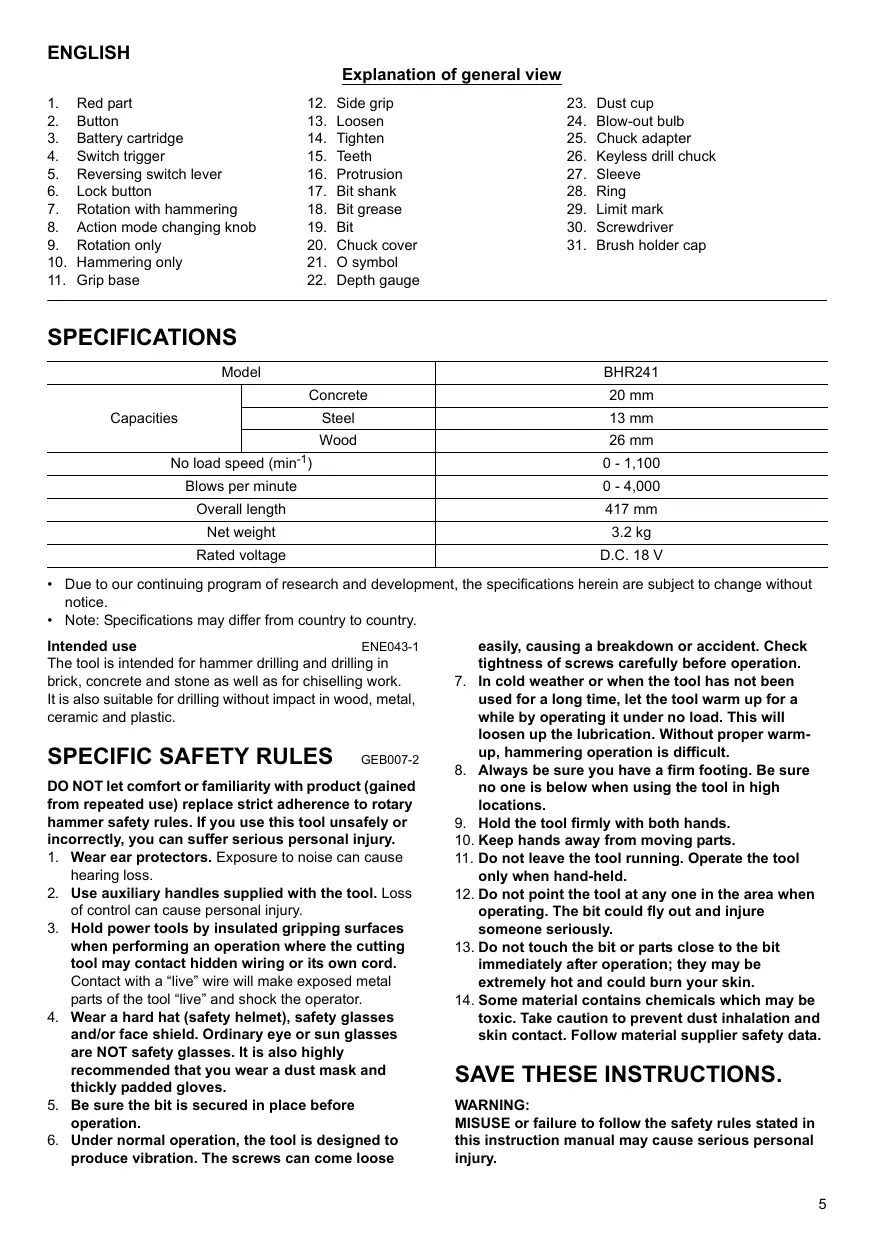
GB Cordless Combination Hammer Instruction manual
| F | Martea combiné sans fil | Manuel d'instructions |
| D | Akku-Kombi-Hammer | Betriebsanleitung |
| I | Martello combinato a batteria | Istruzioni per l'uso |
| NL | Accucombinatiehamer | Gebruiksaanwijzing |
| E | Martillo combinado sin cable | Manual de instrucciones |
| P | Martelo combinado sem fios | Manual de instruções |
| DK | Kabelfri kombihammer | Brugsanvisning |
| GR | Πνεματικό-σακαπικό δράπavo μηαταρίας | Οδηγές χρήσης |
BHR241
1
2
3
4
5
6
7
8
9
10
11
12
13
14
15
16
17
18
19
20
21
ENGLISH
Explanation of general view
-
Red part
-
Side grip
-
Dust cup
-
Button
-
Loosen
-
Blow-out bulb
-
Battery cartridge
-
Tighten
-
Chuck adapter
-
Switch trigger
-
Teeth
-
Keyless drill chuck
-
Reversing switch lever
-
Protrusion
-
Sleeve
-
Lock button
-
Bit shank
-
Ring
-
Rotation with hammering
-
Bit grease
-
Limit mark
-
Action mode changing knob
-
Bit
-
Screwdriver
-
Rotation only
-
Chuck cover
-
Brush holder cap
-
Hammering only
-
O symbol
-
Grip base
-
Depth gauge
SPECIFICATIONS
| Model | BHR241 | |
| Capacities | Concrete | 20 mm |
| Steel | 13 mm | |
| Wood | 26 mm | |
| No load speed (min-1) | 0 - 1,100 | |
| Blows per minute | 0 - 4,000 | |
| Overall length | 417 mm | |
| Net weight | 3.2 kg | |
| Rated voltage | D.C. 18 V | |
- Due to our continuing program of research and development, the specifications herein are subject to change without notice.
Note: Specifications may differ from country to country.
Intended use
ENE043-1
The tool is intended for hammer drilling and drilling in brick, concrete and stone as well as for chiselling work. It is also suitable for drilling without impact in wood, metal, ceramic and plastic.
SPECIFIC SAFETY RULES
GEB007-2
DO NOT let comfort or familiarity with product (gained from repeated use) replace strict adherence to rotary hammer safety rules. If you use this tool unsafely or incorrectly, you can suffer serious personal injury.
- Wear ear protectors. Exposure to noise can cause hearing loss.
- Use auxiliary handles supplied with the tool. Loss of control can cause personal injury.
- Hold power tools by insulated gripping surfaces when performing an operation where the cutting tool may contact hidden wiring or its own cord. Contact with a "live" wire will make exposed metal parts of the tool "live" and shock the operator.
- Wear a hard hat (safety helmet), safety glasses and/or face shield. Ordinary eye or sun glasses are NOT safety glasses. It is also highly recommended that you wear a dust mask and thickly padded gloves.
- Be sure the bit is secured in place before operation.
- Under normal operation, the tool is designed to produce vibration. The screws can come loose
easily, causing a breakdown or accident. Check tightness of screws carefully before operation.
- In cold weather or when the tool has not been used for a long time, let the tool warm up for a while by operating it under no load. This will loosen up the lubrication. Without proper warm-up, hammering operation is difficult.
- Always be sure you have a firm footing. Be sure no one is below when using the tool in high locations.
- Hold the tool firmly with both hands.
- Keep hands away from moving parts.
- Do not leave the tool running. Operate the tool only when hand-held.
- Do not point the tool at any one in the area when operating. The bit could fly out and injure someone seriously.
- Do not touch the bit or parts close to the bit immediately after operation; they may be extremely hot and could burn your skin.
- Some material contains chemicals which may be toxic. Take caution to prevent dust inhalation and skin contact. Follow material supplier safety data.
SAVE THESE INSTRUCTIONS.
WARNING:
MISUSE or failure to follow the safety rules stated in this instruction manual may cause serious personal injury.
FOR BATTERY CARTRIDGE
- Before using battery cartridge, read all instructions and cautionary markings on (1) battery charger, (2) battery, and (3) product using battery.
- Do not disassemble battery cartridge.
- If operating time has become excessively shorter, stop operating immediately. It may result in a risk of overheating, possible burns and even an explosion.
- If electrolyte gets into your eyes, rinse them out with clear water and seek medical attention right away. It may result in loss of your eyesight.
- Do not short the battery cartridge:
(1) Do not touch the terminals with any conductive material.
(2) Avoid storing battery cartridge in a container with other metal objects such as nails, coins, etc.
(3) Do not expose battery cartridge to water or rain.
A battery short can cause a large current flow, overheating, possible burns and even a breakdown.
- Do not store the tool and battery cartridge in locations where the temperature may reach or exceed 50°C (122°F) .
- Do not incinerate the battery cartridge even if it is severely damaged or is completely worn out. The battery cartridge can explode in a fire.
- Be careful not to drop or strike battery.
SAVE THESE INSTRUCTIONS.
Tips for maintaining maximum battery life
- Charge the battery cartridge before completely discharged. Always stop tool operation and charge the battery cartridge when you notice less tool power.
- Never recharge a fully charged battery cartridge. Overcharging shortens the battery service life.
- Charge the battery cartridge with room temperature at 10°C - 40°C (50°F - 104°F) . Let a hot battery cartridge cool down before charging it.
FUNCTIONAL DESCRIPTION
CAUTION:
- Always be sure that the tool is switched off and the battery cartridge is removed before adjusting or checking function on the tool.
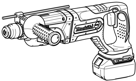
Installing or removing battery cartridge (Fig. 1)
Always switch off the tool before insertion or removal of the battery cartridge.
- To remove the battery cartridge, withdraw it from the tool while sliding the button on the front of the cartridge.
- To insert the battery cartridge, align the tongue on the battery cartridge with the groove in the housing and slip it into place. Always insert it all the way until it locks in place with a little click. If you can see the red part on the upper side of the button, it is not locked completely. Insert it fully until the red part cannot be seen. If not, it may accidentally fall out of the tool, causing injury to you or someone around you.
- Do not use force when inserting the battery cartridge. If the cartridge does not slide in easily, it is not being inserted correctly.
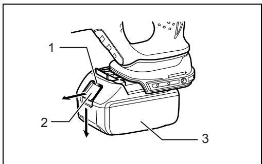
Switch action (Fig. 2)
CAUTION:
- Before inserting the battery cartridge into the tool, always check to see that the switch trigger actuates properly and returns to the "OFF" position when released.
To start the tool, simply pull the switch trigger. Tool speed is increased by increasing pressure on the switch trigger. Release the switch trigger to stop.
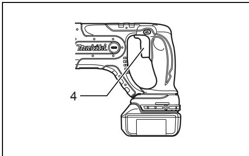
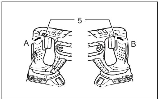
Reversing switch action (Fig. 3)
This tool has a reversing switch to change the direction of rotation. Depress the reversing switch lever from the A side for clockwise rotation or from the B side for counterclockwise rotation.
When the reversing switch lever is in the neutral position, the switch trigger cannot be pulled.
CAUTION:
Always check the direction of rotation before operation.
- Use the reversing switch only after the tool comes to a complete stop. Changing the direction of rotation before the tool stops may damage the tool.
- When not operating the tool, always set the reversing switch lever to the neutral position.
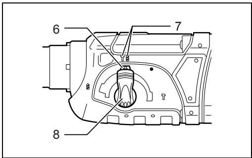
Selecting the action mode
Rotation with hammering (Fig. 4)
For drilling in concrete, masonry, etc., depress the lock button and rotate the action mode changing knob to the symbol. Use a tungsten-carbide tipped bit.
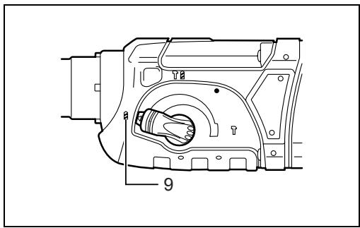
Rotation only (Fig. 5)
For drilling in wood, metal or plastic materials, depress the lock button and rotate the action mode changing knob to the symbol. Use a twist drill bit or wood bit.
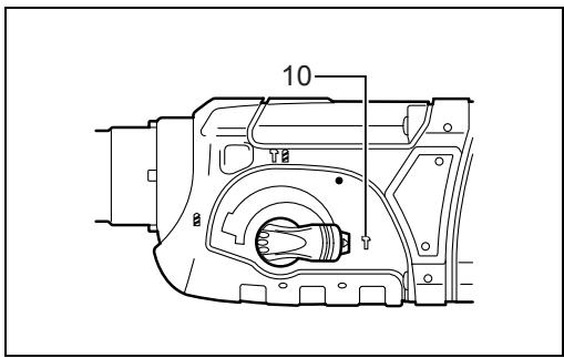
Hammering only (Fig. 6)
For chipping, scaling or demolition operations, depress the lock button and rotate the action mode changing knob to the symbol. Use a bull point, cold chisel, scaling chisel, etc.
CAUTION:
- Do not rotate the action mode changing knob when the tool is running. The tool will be damaged.
- To avoid rapid wear on the mode change mechanism, be sure that the action mode changing knob is always positively located in one of the three action mode positions.
Torque limiter
The torque limiter will actuate when a certain torque level is reached. The motor will disengage from the output shaft. When this happens, the bit will stop turning.
CAUTION:
- As soon as the torque limiter actuates, switch off the tool immediately. This will help prevent premature wear of the tool.
- Hole saws cannot be used with this tool. They tend to pinch or catch easily in the hole. This will cause the torque limiter to actuate too frequently.
ASSEMBLY
CAUTION:
- Always be sure that the tool is switched off and the battery cartridge is removed before carrying out any work on the tool.
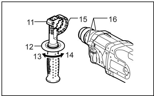
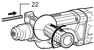
Side grip (auxiliary handle) (Fig. 7)
CAUTION:
Always use the side grip to ensure operating safety. Install the side grip so that the teeth on the grip fit in between the protrusions on the tool barrel. Then tighten the grip by turning clockwise at the desired position. It may be swung 360° so as to be secured at any position.
Bit grease
Coat the bit shank head beforehand with a small amount of bit grease (about 0.5 -1 g). This chuck lubrication assures smooth action and longer service life.
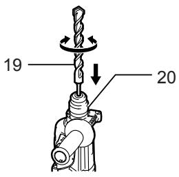
Installing or removing the bit
Clean the bit shank and apply bit grease before installing the bit. (Fig. 8)
Insert the bit into the tool. Turn the bit and push it in until it engages. (Fig. 9)
If the bit cannot be pushed in, remove the bit. Pull the chuck cover down a couple of times. Then insert the bit again. Turn the bit and push it in until it engages.
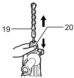
After installing, always make sure that the bit is securely held in place by trying to pull it out.
To remove the bit, pull the chuck cover down all the way and pull the bit out. (Fig. 10)
Bit angle (when chipping, scaling or demolishing) (Fig. 11)
The bit can be secured at the desired angle. To change the bit angle, depress the lock button and rotate the action mode changing knob to the O symbol. Turn the bit to the desired angle.
Depress the lock button and rotate the action mode changing knob to the symbol. Then make sure that the bit is securely held in place by turning it slightly. (Fig. 12)
Depth gauge (Fig. 13)
The depth gauge is convenient for drilling holes of uniform depth. Loosen the side grip and insert the depth gauge into the hole in the side grip. Adjust the depth gauge to the desired depth and tighten the side grip.
NOTE:
- The depth gauge cannot be used at the position where the depth gauge strikes against the gear housing.
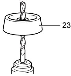
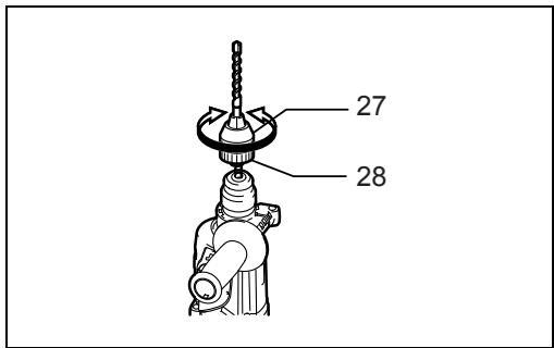
Dust cup (Fig. 14)
Use the dust cup to prevent dust from falling over the tool and on yourself when performing overhead drilling operations. Attach the dust cup to the bit as shown in the figure. The size of bits which the dust cup can be attached to is as follows.
| Bit diameter | |
| Dust cup 5 | 6 mm - 14.5 mm |
| Dust cup 9 | 12 mm - 16 mm |
OPERATION
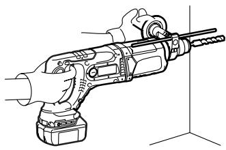
Hammer drilling operation (Fig. 15)
Set the action mode changing knob to the symbol.
Position the bit at the desired location for the hole, then pull the switch trigger.
Do not force the tool. Light pressure gives best results. Keep the tool in position and prevent it from slipping away from the hole.
Do not apply more pressure when the hole becomes clogged with chips or particles. Instead, run the tool at an idle, then remove the bit partially from the hole. By repeating this several times, the hole will be cleaned out and normal drilling may be resumed.
CAUTION:
- There is a tremendous and sudden twisting force exerted on the tool/bit at the time of hole breakthrough, when the hole becomes clogged with chips and particles, or when striking reinforcing rods embedded in the concrete. Always use the side grip (auxiliary handle) and firmly hold the tool by both side grip and switch handle during operations. Failure to do so may result in the loss of control of the tool and potentially severe injury.
NOTE:
Eccentricity in the bit rotation may occur while operating the tool with no load. The tool automatically centers itself during operation. This does not affect the drilling precision.
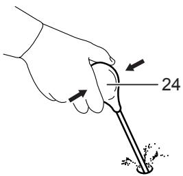
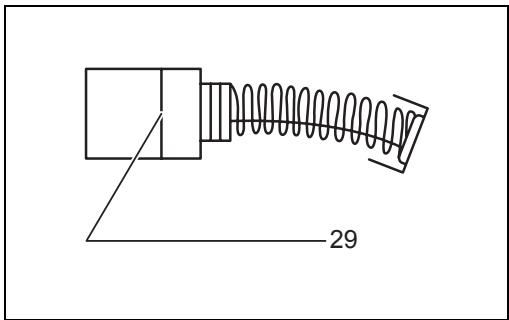
Blow-out bulb (optional accessory) (Fig. 16)
After drilling the hole, use the blow-out bulb to clean the dust out of the hole.
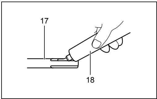
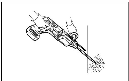
Chipping/Scaling/Demolition (Fig. 17)
Set the action mode changing knob to the symbol. Hold the tool firmly with both hands. Turn the tool on and apply slight pressure on the tool so that the tool will not bounce around, uncontrolled. Pressing very hard on the tool will not increase the efficiency.
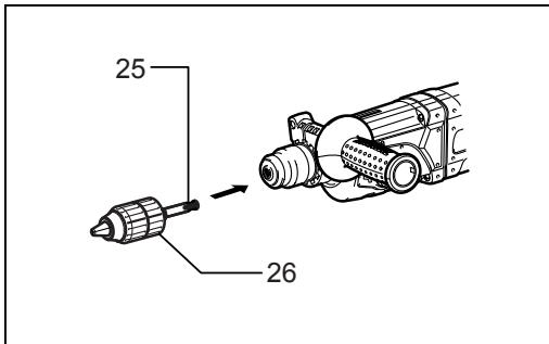
Drilling in wood or metal (Fig. 18 & 19)
Use the optional drill chuck assembly. When installing it, refer to "Installing or removing the bit" described on the
previous page. Set the action mode changing knob so that the pointer points to the 3/2 symbol.
CAUTION:
- Never use "rotation with hammering" when the drill chuck assembly is installed on the tool. The drill chuck assembly may be damaged. Also, the drill chuck will come off when reversing the tool.
- Pressing excessively on the tool will not speed up the drilling. In fact, this excessive pressure will only serve to damage the tip of your bit, decrease the tool performance and shorten the service life of the tool.
- There is a tremendous twisting force exerted on the tool/bit at the time of hole breakthrough. Hold the tool firmly and exert care when the bit begins to break through the workpiece.
- A stuck bit can be removed simply by setting the reversing switch to reverse rotation in order to back out. However, the tool may back out abruptly if you do not hold it firmly.
- Always secure small workpieces in a vise or similar hold-down device.
MAINTENANCE
CAUTION:
- Always be sure that the tool is switched off and the battery cartridge is removed before attempting to perform inspection or maintenance.
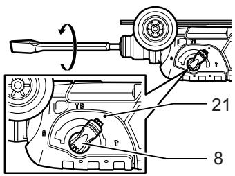
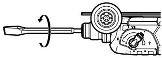
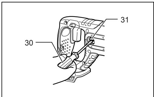
Replacing carbon brushes (Fig. 20)
Remove and check the carbon brushes regularly.
Replace when they wear down to the limit mark. Keep the carbon brushes clean and free to slip in the holders.
Both carbon brushes should be replaced at the same time. Use only identical carbon brushes.
Use a screwdriver to remove the brush holder caps.
Take out the worn carbon brushes, insert the new ones and secure the brush holder caps. (Fig. 21)
To maintain product SAFETY and RELIABILITY, repairs, any other maintenance or adjustment should be performed by Makita Authorized Service Centers, always using Makita replacement parts.
ACCESSORIES
CAUTION:
- These accessories or attachments are recommended for use with your Makita tool specified in this manual. The use of any other accessories or attachments might present a risk of injury to persons. Only use accessory or attachment for its stated purpose.
If you need any assistance for more details regarding these accessories, ask your local Makita Service Center.
SDS-Plus Carbide-tipped bits - Bull point
Cold chisel - Scaling chisel
Grooving chisel - Drill chuck assembly
- Drill chuck S13
- Chuck adapter
-
Chuck key S13
Bit grease
Side grip -
Depth gauge
- Blow-out bulb
Dust cup - Dust extractor attachment
- Safety goggles
- Plastic carrying case
Keyless drill chuck - Various type of Makita genuine batteries and chargers
For European countries only
Noise
ENG102-1
The typical A-weighted noise level determined according to EN60745-2-6:
Sound pressure level (LpA) : 86 dB (A)
Sound power level (LWA) : 97 dB (A)
Uncertainty (K): 3 dB (A)
Wear ear protection
Vibration
ENG215-1
The vibration total value (tri-axial vector sum) determined according to EN60745-2-6:
Work mode: chiseling function
Vibration emission (ah,CHeq) : 9.5 m/s2
Uncertainty (K): 1.5m / s2
ENG303-1
Work mode: hammer drilling into concrete, 10 mm diameter and 100 mm depth
Vibration emission (ah,HD) .. 12.5m / s2
Uncertainty (K): 1.5m / s2
ENG302-1
Work mode: drilling into metal
Vibration emission (ah,D) .. 2.5m / s2 or less
EC-DECLARATION OF CONFORMITY
ENH102-8
Model; BHR241
We declare under our sole responsibility that this product is in compliance with the following standards of standardized documents;
EN60745, EN55014 in accordance with Council
Directives, 2004/108/EC, 98/37/EC.

CE 2008
Tomoyasu Kato
Director
Responsible Manufacturer:
Makita Corporation
3-11-8, Sumiyoshi-cho, Anjo, Aichi, JAPAN
Authorized Representative in Europe:
Makita International Europe Ltd.
Michigan Drive, Tongwell, Milton Keynes, Bucks MK15 8JD, ENGLAND
FRANÇAIS
Descriptif
Burinage/Ecaillage/Demolition (Fig. 17)
Fabricant responsible :
Makita Corporation
3-11-8, Sumiyoshi-cho, Anjo, Aichi, JAPAN
Representant agreé en Europe :
Makita International Europe Ltd.
Michigan Drive, Tongwell, Milton Keynes, Bucks MK15 8JD, ANGLETERRE
DEUTSCH
Michigan Drive, Tongwell, Milton Keynes, Bucks MK15 8JD, ENGLAND
ITALIANO
3-11-8, Sumiyoshi-cho, Anjo, Aichi, GIAPPONE
Michigan Drive, Tongwell, Milton Keynes, Bucks MK15 8JD, INGHILTERRA
NEDERLANDS
Tomoyasu Kato
Director
Michigan Drive, Tongwell, Milton Keynes, Bucks MK15 8JD, ENGELAND
ESPANOL
Michigan Drive, Tongwell, Milton Keynes, Bucks MK15
8JD, ENGLAND
Descrição geral
Conselho, 2004/108/CE, 98/37/CE.
CE 2008

Tomoyasu Kato
Administrator
Fabricante responsavel:
Makita Corporation
3-11-8, Sumiyoshi-cho, Anjo, Aichi, JAPAO
Representante autorizzato na Europa:
Makita International Europe Ltd.
Michigan Drive, Tongwell, Milton Keynes, Bucks MK15
8JD, INGLATERRA
DANSK
Michigan Drive, Tongwell, Milton Keynes, Bucks MK15
8JD, ENGLAND
EAAHNIKA
Tia eupwnaikec xwpes povo
Oópuβoc
ENG102-1
To ouvnoec oTaouevo enineo 0opou nou exi Kaotopoi eouwva u Tnv EN60745-2-6:
Michigan Drive, Tongwell, Milton Keynes, Bucks MK15 8JD, AITAIA
Makita Corporation
Anjo, Aichi, Japan
884838-996
- ENGLISH
- EXPLANATION OF GENERAL VIEW
- SPECIFICATIONS
- INTENDED USE
- SPECIFIC SAFETY RULES
- SAVE THESE INSTRUCTIONS
- WARNING
- FOR BATTERY CARTRIDGE
- TIPS FOR MAINTAINING MAXIMUM BATTERY LIFE
- FUNCTIONAL DESCRIPTION
- CAUTION
- INSTALLING OR REMOVING BATTERY CARTRIDGE (FIG. 1)
- SWITCH ACTION (FIG. 2)
- REVERSING SWITCH ACTION (FIG. 3)
- SELECTING THE ACTION MODE
- ROTATION WITH HAMMERING (FIG. 4)
- ROTATION ONLY (FIG. 5)
- HAMMERING ONLY (FIG. 6)
- TORQUE LIMITER
- ASSEMBLY
- SIDE GRIP (AUXILIARY HANDLE) (FIG. 7)
- BIT GREASE
- INSTALLING OR REMOVING THE BIT
- BIT ANGLE (WHEN CHIPPING, SCALING OR DEMOLISHING) (FIG. 11)
- DEPTH GAUGE (FIG. 13)
- NOTE
- DUST CUP (FIG. 14)
- OPERATION
- HAMMER DRILLING OPERATION (FIG. 15)
- BLOW-OUT BULB (OPTIONAL ACCESSORY) (FIG. 16)
- CHIPPING/SCALING/DEMOLITION (FIG. 17)
- DRILLING IN WOOD OR METAL (FIG. 18 & 19)
- MAINTENANCE
- REPLACING CARBON BRUSHES (FIG. 20)
- ACCESSORIES
- FOR EUROPEAN COUNTRIES ONLY
- NOISE
- WEAR EAR PROTECTION
- VIBRATION
- EC-DECLARATION OF CONFORMITY
- MODEL; BHR241
- MAKITA CORPORATION
- MAKITA INTERNATIONAL EUROPE LTD
- FRANÇAIS
- DESCRIPTIF
- BURINAGE/ECAILLAGE/DEMOLITION (FIG. 17)
- DEUTSCH
- ITALIANO
- NEDERLANDS
- ESPANOL
- DESCRIÇÃO GERAL
- DANSK
- EAAHNIKA
- TIA EUPWNAIKEC XWPES POVO
- OÓPUΒOC
Brand : MAKITA
Model : BHR241
Category : Jackhammer