
Hr4002 - Jackhammer MAKITA - Free user manual and instructions
Find the device manual for free Hr4002 MAKITA in PDF.
| Product Type | Demolition hammer (rotary hammer) |
| Brand | MAKITA |
| Model | HR4002 |
| Drilling capacity (carbide bit) | 40 mm |
| Core bit capacity | 105 mm |
| No-load speed | 680 min-1 |
| Impact rate | 2,500 blows/min |
| Overall length | 458 mm |
| Net weight | 6.2 kg |
| Safety rating | Double insulation (Class II) |
| Power supply | Single-phase mains, voltage according to rating plate |
| Operating modes | Rotary hammering, hammer only (chiseling/scaling/demolition) |
| Bit retention system | SDS-Max |
| Side handle | Adjustable 360° vertically, 8 horizontal positions |
| Side grip | Adjustable, attaches on either side |
| Depth gauge | Integrated, adjustable |
| Torque limiter | Yes, disengages the motor in case of jamming |
| Lubrication | Grease lubrication, servicing at authorized center |
| Sound pressure level (L_pA) | 93 dB(A) with uncertainty K=3 dB(A) |
| Sound power level (L_WA) | 104 dB(A) with uncertainty K=3 dB(A) |
| Vibrations (drilling with hammering) | 17 m/s² with uncertainty K=1.5 m/s² |
| Vibrations (chiseling) | 10.5 m/s² with uncertainty K=2 m/s² |
| Standard accessories | Side handle, side grip, depth gauge, blow bulb |
Frequently Asked Questions - Hr4002 MAKITA
User questions about Hr4002 MAKITA
0 question about this device. Answer the ones you know or ask your own.
Ask a new question about this device
Download the instructions for your Jackhammer in PDF format for free! Find your manual Hr4002 - MAKITA and take your electronic device back in hand. On this page are published all the documents necessary for the use of your device. Hr4002 by MAKITA.
USER MANUAL Hr4002 MAKITA
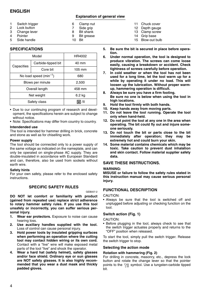
Explanation of general view
1 Switch trigger
2 Lock button
3 Change lever
4 Pointer
5 Side handle
6 Clamp nut
7 Side grip
8 Bit shank
9 Bit grease
10 Bit
11 Chuck cover
12 Depth gauge
13 Clamp screw
14 Grip base
15 Blow-out bulb
SPECIFICATIONS
| Model | HR4002 | |
| Capacities | Carbide-tipped bit | 40 mm |
| Core bit | 105 mm | |
| No load speed (min-1) | 680 | |
| Blows per minute | 2,500 | |
| Overall length | 458 mm | |
| Net weight | 6.2 kg | |
| Safety class | ☐ /II | |
- Due to our continuing program of research and development, the specifications herein are subject to change without notice.
- Note: Specifications may differ from country to country.
Intended use
The tool is intended for hammer drilling in brick, concrete and stone as well as for chiselling work.
Power supply
The tool should be connected only to a power supply of the same voltage as indicated on the nameplate, and can only be operated on single-phase AC supply. They are double-insulated in accordance with European Standard and can, therefore, also be used from sockets without earth wire.
Safety hints
For your own safety, please refer to the enclosed safety instructions.
SPECIFIC SAFETY RULES
GEB007-2
DO NOT let comfort or familiarity with product (gained from repeated use) replace strict adherence to rotary hammer safety rules. If you use this tool unsafely or incorrectly, you can suffer serious personal injury.
- Wear ear protectors. Exposure to noise can cause hearing loss.
- Use auxiliary handles supplied with the tool. Loss of control can cause personal injury.
- Hold power tools by insulated gripping surfaces when performing an operation where the cutting tool may contact hidden wiring or its own cord. Contact with a "live" wire will make exposed metal parts of the tool "live" and shock the operator.
-
Wear a hard hat (safety helmet), safety glasses and/or face shield. Ordinary eye or sun glasses are NOT safety glasses. It is also highly recommended that you wear a dust mask and thickly padded gloves.
-
Be sure the bit is secured in place before operation.
- Under normal operation, the tool is designed to produce vibration. The screws can come loose easily, causing a breakdown or accident. Check tightness of screws carefully before operation.
- In cold weather or when the tool has not been used for a long time, let the tool warm up for a while by operating it under no load. This will loosen up the lubrication. Without proper warm-up, hammering operation is difficult.
- Always be sure you have a firm footing. Be sure no one is below when using the tool in high locations.
- Hold the tool firmly with both hands.
- Keep hands away from moving parts.
- Do not leave the tool running. Operate the tool only when hand-held.
- Do not point the tool at any one in the area when operating. The bit could fly out and injure someone seriously.
- Do not touch the bit or parts close to the bit immediately after operation; they may be extremely hot and could burn your skin.
- Some material contains chemicals which may be toxic. Take caution to prevent dust inhalation and skin contact. Follow material supplier safety data.
SAVE THESE INSTRUCTIONS.
WARNING:
MISUSE or failure to follow the safety rules stated in this instruction manual may cause serious personal injury.
FUNCTIONAL DESCRIPTION
CAUTION:
Always be sure that the tool is switched off and unplugged before adjusting or checking function on the tool.
Switch action (Fig. 1)
CAUTION:
- Before plugging in the tool, always check to see that the switch trigger actuates properly and returns to the "OFF" position when released.
To start the tool, simply pull the switch trigger. Release the switch trigger to stop.
Selecting the action mode
Rotation with hammering (Fig. 2)
For drilling in concrete, masonry, etc., depress the lock button and rotate the change lever so that the pointer points to the symbol. Use a tungsten-carbide tipped bit.
Hammering only (Fig. 3)
For chipping, scaling or demolition operations, depress the lock button and rotate the change lever so that the pointer points to the symbol. Use a bull point, cold chisel, scaling chisel, etc.
CAUTION:
- Do not rotate the change lever when the tool is running under load. The tool will be damaged.
- To avoid rapid wear on the mode change mechanism, be sure that the change lever is always positively located in one of the two or three action mode positions.
Torque limiter
The torque limiter will actuate when a certain torque level is reached. The motor will disengage from the output shaft. When this happens, the bit will stop turning.
CAUTION:
- As soon as the torque limiter actuates, switch off the tool immediately. This will help prevent premature wear of the tool.
ASSEMBLY
CAUTION:
- Always be sure that the tool is switched off and unplugged before carrying out any work on the tool.
Side handle (accessory) (Fig. 4)
CAUTION:
- Use the side handle only when chipping, scaling or demolishing. Do not use it when drilling in concrete, masonry, etc. The tool cannot be held properly with this side handle when drilling.
The side handle can be swung 360irc on the vertical and secured at any desired position. It also secures at eight different positions back and forth on the horizontal. Just loosen the clamp nut to swing the side handle to a desired position. Then tighten the clamp nut securely. (Fig. 5)
Side grip (Fig. 6)
CAUTION:
- Always use the side grip to ensure operating safety when drilling in concrete, masonry, etc.
The side grip swings around to either side, allowing easy handling of the tool in any position. Loosen the side grip by turning it counterclockwise, swing it to the desired position and then tighten it by turning clockwise.
Bit grease (optional accessory)
Coat the bit shank head beforehand with a small amount of bit grease (about 0.5 - 1g . 0.02 - 0.04 oz.). This chuck lubrication assures smooth action and longer service life.
Installing or removing the bit
Clean the bit shank and apply bit grease before installing the bit. (Fig. 7)
Insert the bit into the tool. Turn the bit and push it in until it engages.
If the bit cannot be pushed in, remove the bit. Pull the chuck cover down a couple of times. Then insert the bit again. Turn the bit and push it in until it engages. (Fig. 8)
After installing, always make sure that the bit is securely held in place by trying to pull it out.
To remove the bit, pull the chuck cover down all the way and pull the bit out. (Fig. 9)
Bit angle (when chipping, scaling or demolishing)
The bit can be secured at 12 different angles. To change the bit angle, depress the lock button and rotate the change lever so that the pointer points to the symbol. Turn the bit to the desired angle. (Fig. 10)
Depress the lock button and rotate the change lever so that the pointer points to the symbol. Then make sure that the bit is securely held in place by turning it slightly. (Fig. 11)
Depth gauge (Fig. 12)
The depth gauge is convenient for drilling holes of uniform depth. Insert the depth gauge into the hole in the grip base. Adjust the depth gauge to the desired depth and then tighten the clamp screw to secure the depth gauge.
The depth gauge is convenient for drilling holes of uniform depth. Loosen the clamp screw and adjust the depth gauge to the desired depth. After adjusting, tighten the clamp screw firmly.
NOTE:
- The depth gauge cannot be used at the position where the depth gauge strikes against the tool body.
- The depth gauge cannot be used at the position where the depth gauge strikes against the gear housing/motor housing.
OPERATION
Hammer drilling operation (Fig. 13)
Set the change lever to the symbol.
Position the bit at the desired location for the hole, then pull the switch trigger. Do not force the tool. Light pressure gives best results. Keep the tool in position and prevent it from slipping away from the hole.
Do not apply more pressure when the hole becomes clogged with chips or particles. Instead, run the tool at an idle, then remove the bit partially from the hole. By repeating this several times, the hole will be cleaned out and normal drilling may be resumed.
CAUTION:
- When the bit begins to break through concrete or if the bit strikes reinforcing rods embedded in concrete, the tool may react dangerously. Maintain good balance and safe footing while holding the tool firmly with both hands to prevent dangerous reaction.
Blow-out bulb (optional accessory) (Fig. 14)
After drilling the hole, use the blow-out bulb to clean the dust out of the hole.
Chipping/Scaling/Demolition (Fig. 15)
Set the change lever to the symbol.
Hold the tool firmly with both hands. Turn the tool on and apply slight pressure on the tool so that the tool will not bounce around, uncontrolled. Pressing very hard on the tool will not increase the efficiency.
MAINTENANCE
CAUTION:
Always be sure that the tool is switched off and unplugged before attempting to perform inspection or maintenance.
Lubrication
CAUTION:
- This servicing should be performed by Makita Authorized or Factory Service Centers only.
This tool requires no hourly or daily lubrication because it has a grease-packed lubrication system. It should be relubricated regularly. Send the complete tool to Makita Authorized or Factory Service Center for this lubrication service.
To maintain product SAFETY and RELIABILITY, repairs, any other maintenance or adjustment should be performed by Makita Authorized Service Centers, always using Makita replacement parts.
ACCESSORIES
CAUTION:
- These accessories or attachments are recommended for use with your Makita tool specified in this manual. The use of any other accessories or attachments might present a risk of injury to persons. Only use accessory or attachment for its stated purpose.
If you need any assistance for more details regarding these accessories, ask your local Makita service center. - SDS-Max Carbide-tipped bits
- SDS-Max bull point
- SDS-Max cold chisel
SDS-Max scaling chisel
SDS-Max tile chisel - SDS-Max clay spade
- Hammer grease
- Bit grease
- Side handle
- Side grip
- Depth gauge
- Blow-out bulb
- Safety goggles
- Carrying case
1 Gachette
6 Écrou de serrage
EC-DECLARATION OF CONFORMITY
Model; HR4002
We declare under our sole responsibility that this product is in compliance with the following standards of standardized documents,
EN60745, EN55014, EN61000
in accordance with Council Directives, 2004/108/EC and 98/37/EC.
FRANÇAISE
Déclaration de CONFORMITE CE
Modèle ; HR4002
Responsible manufacturer:
Fabricant responsible :
Authorized Representative in Europe:
Michigan Drive, Tongwell, Milton Keynes, Bucks MK15 8JD, ENGLAND
PORTUGUES
DECLARATION DE CONFORMIDADE DA CE
Modelo; HR4002
Declaramos sob inteira responsabilité que este produits obedoce às segentes normas de documents normalizados,
EN60745, EN55014, EN61000
de accordo com as directivas 2004/108/CE e 98/37/CE do Conselho.
DANSK
EU-DEKLARATION OM KONFORMITET
Model; HR4002
Michigan Drive, Tongwell, Milton Keynes, Bucks MK15 8JD, ENGLAND
ENGLISH
For European countries only
Noise
The typical A-weighted noise level determined according to EN60745-2-6:
Sound pressure level (LpA) : 93 dB (A)
Sound power level (LWA) : 104 dB (A)
Uncertainty (K): 3 dB (A)
Wear ear protection.
Valibration
The vibration total value (tri-axial vector sum) determined according to EN60745-2-6:
Work mode: chiseling function
Vibration emission (h,CHeq) .. 10.5m / s2
Uncertainty (K): 2m / s2
Work mode: hammer drilling into concrete, 20mm diameter and 180 mm depth
Vibration emission (ah,HD) .. 17 m / s2
Uncertainty (K): 1.5m / s2
FRANÇAISE
Móvo yia xwpe ts Eupwnns
Oópuβoc

- Explanation of general view
- Intended use
- Power supply
- Safety hints
- SPECIFIC SAFETY RULES
- SAVE THESE INSTRUCTIONS.
- WARNING:
- FUNCTIONAL DESCRIPTION
- CAUTION:
- Switch action (Fig. 1)
- Selecting the action mode
- Rotation with hammering (Fig. 2)
- Hammering only (Fig. 3)
- Torque limiter
- ASSEMBLY
- Side handle (accessory) (Fig. 4)
- Side grip (Fig. 6)
- Bit grease (optional accessory)
- Installing or removing the bit
- Bit angle (when chipping, scaling or demolishing)
- Depth gauge (Fig. 12)
- NOTE:
- OPERATION
- Hammer drilling operation (Fig. 13)
- Blow-out bulb (optional accessory) (Fig. 14)
- Chipping/Scaling/Demolition (Fig. 15)
- MAINTENANCE
- Lubrication
- ACCESSORIES
- EC-DECLARATION OF CONFORMITY
- Model; HR4002
- FRANÇAISE
- Déclaration de CONFORMITE CE
- Modèle ; HR4002
- PORTUGUES
- DECLARATION DE CONFORMIDADE DA CE
- Modelo; HR4002
- DANSK
- EU-DEKLARATION OM KONFORMITET
- ENGLISH
- For European countries only
- Noise
- Wear ear protection.
- Valibration
- Móvo yia xwpe ts Eupwnns
- Oópuβoc
Brand : MAKITA
Model : Hr4002
Category : Jackhammer