
HM1202 - Jackhammer MAKITA - Free user manual and instructions
Find the device manual for free HM1202 MAKITA in PDF.
| Product Type | Breaker Hammer |
| Brand | Makita |
| Models | HM1202, HM1202C |
| Supply Voltage | 230 V (single-phase, ~50/60 Hz) |
| Double Insulation | Yes (Class II) |
| Blow Rate | 1,900 min⁻¹ (HM1202) / 950–1,900 min⁻¹ (HM1202C) |
| Overall Length | 578 mm |
| Net Weight | 9.9 kg (HM1202) / 10.0 kg (HM1202C) |
| Chuck Type | SDS-max |
| Sound Pressure Level | 85 dB(A) |
| Sound Power Level | 99 dB(A) |
| Vibrations (Chiselling) | 16.5 m/s² (uncertainty 1.5 m/s²) |
| Suitable Materials | Concrete, brick, stone, asphalt |
| Side Handle | Yes, adjustable 360° |
| Speed Adjustment | Yes (HM1202C only, 6-position dial) |
| Brush Wear Indicator | Yes (red, HM1202C) |
| Lubrication | Every 6 months, Makita special grease (30 g) |
| Brush Replacement | Self-service, auto-stop at end of life |
| Included Accessories | Pink grease, socket wrench, screwdriver |
| Applications | Chiseling, scaling, demolition, digging, compacting |
Frequently Asked Questions - HM1202 MAKITA
User questions about HM1202 MAKITA
0 question about this device. Answer the ones you know or ask your own.
Ask a new question about this device
Download the instructions for your Jackhammer in PDF format for free! Find your manual HM1202 - MAKITA and take your electronic device back in hand. On this page are published all the documents necessary for the use of your device. HM1202 by MAKITA.
USER MANUAL HM1202 MAKITA


1
2
3
4
5
6

7

8
9
10

11
12
13
14

15
16
Explanation of general view
| 1 | Switch lever | 8 | Bit grease | 16 | Screwdriver |
| 2 | Adjusting dial | 9 | Bit shank | 17 | Rear cover |
| 3 | Power-ON indicator lamp (green) | 10 | Bit | 18 | Screws |
| 11 | Tool holder cover | 19 | Brush holder cap | ||
| 4 | Service indicator lamp (red) | 12 | Change ring | 20 | Socket wrench |
| 5 | Side handle | 13 | Commutator | 21 | Crank cap |
| 6 | Clamp nut | 14 | Insulating tip | 22 | Hammer grease |
| 7 | Side handle base | 15 | Carbon brush |
SPECIFICATIONS
| Model | HM1202 | HM1202C |
| Blows per minute (min -1 ) | 1,900 | 950 – 1,900 |
| Overall length | 578 mm | 578 mm |
| Net weight | 9.9 kg | 10.0 kg |
| Safety class | ☐/II | ☐/II |
- Due to our continuing program of research and development, the specifications herein are subject to change without notice.
- Specifications may differ from country to country.
• Weight according to EPTA-Procedure 01/2003
ENE045-1
Intended use
The tool is intended for chiselling work in concrete, brick, stone and asphalt as well as for driving and compacting with appropriate accessories.
ENF002-2
Power supply
The tool should be connected only to a power supply of the same voltage as indicated on the nameplate, and can only be operated on single-phase AC supply. They are double-insulated and can, therefore, also be used from sockets without earth wire.
ENF100-1
For public low-voltage distribution systems of between 220 V and 250 V.
Switching operations of electric apparatus cause voltage fluctuations. The operation of this device under unfavorable mains conditions can have adverse effects to the operation of other equipment. With a mains impedance equal or less than 0.46 Ohms it can be presumed that there will be no negative effects. The mains socket used for this device must be protected with a fuse or protective circuit breaker having slow tripping characteristics.
GEA010-1
General Power Tool Safety Warnings
WARNING Read all safety warnings and all instructions. Failure to follow the warnings and instructions may result in electric shock, fire and/or serious injury.
Save all warnings and instructions for future reference.
GEB004-6
HAMMER SAFETY WARNINGS
- Wear ear protectors. Exposure to noise can cause hearing loss.
-
Use auxiliary handle(s), if supplied with the tool. Loss of control can cause personal injury.
-
Hold power tool by insulated gripping surfaces, when performing an operation where the cutting accessory may contact hidden wiring or its own cord. Cutting accessory contacting a "live" wire may make exposed metal parts of the power tool "live" and could give the operator an electric shock.
- Wear a hard hat (safety helmet), safety glasses and/or face shield. Ordinary eye or sun glasses are NOT safety glasses. It is also highly recommended that you wear a dust mask and thickly padded gloves.
- Be sure the bit is secured in place before operation.
- Under normal operation, the tool is designed to produce vibration. The screws can come loose easily, causing a breakdown or accident. Check tightness of screws carefully before operation.
- In cold weather or when the tool has not been used for a long time, let the tool warm up for a while by operating it under no load. This will loosen up the lubrication. Without proper warm-up, hammering operation is difficult.
- Always be sure you have a firm footing. Be sure no one is below when using the tool in high locations.
- Hold the tool firmly with both hands.
- Keep hands away from moving parts.
- Do not leave the tool running. Operate the tool only when hand-held.
- Do not point the tool at any one in the area when operating. The bit could fly out and injure someone seriously.
- Do not touch the bit or parts close to the bit immediately after operation; they may be extremely hot and could burn your skin.
- Do not operate the tool at no-load unnecessarily.
- Some material contains chemicals which may be toxic. Take caution to prevent dust inhalation and skin contact. Follow material supplier safety data.
SAVE THESE INSTRUCTIONS.
! WARNING:
DO NOT let comfort or familiarity with product (gained from repeated use) replace strict adherence to safety rules for the subject product.
MISUSE or failure to follow the safety rules stated in this instruction manual may cause serious personal injury.
FUNCTIONAL DESCRIPTION
CAUTION:
- Always be sure that the tool is switched off and unplugged before adjusting or checking function on the tool.
Switch action (Fig. 1)
CAUTION:
- Before plugging in the tool, always check to see that the tool is switched off.
To start the tool, push the switch lever on the left side of the tool. To stop the tool, push the switch lever on the right side of the tool.
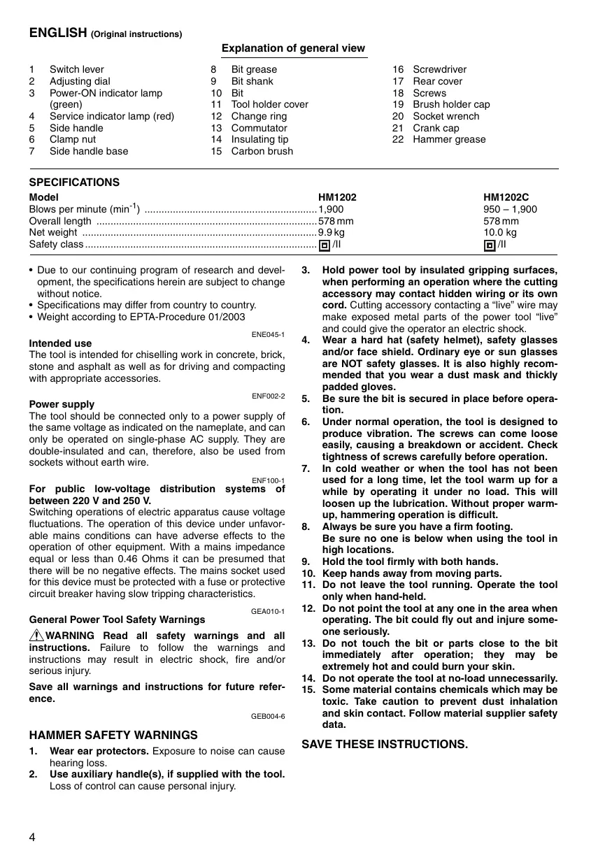
Speed change (Fig. 2)
For HM1202C only
The blows per minute can be adjusted just by turning the adjusting dial. This can be done even while the tool is running. The dial is marked 1 (lowest speed) to 6 (full speed). Refer to the table below for the relationship between the number settings on the adjusting dial and the blows per minute.
| Number on adjusting dial | Blows per minute |
| 6 | 1,900 |
| 5 | 1,800 |
| 4 | 1,600 |
| 3 | 1,300 |
| 2 | 1,050 |
| 1 | 950 |
CAUTION:
- The speed adjusting dial can be turned only as far as 6 and back to 1. Do not force it past 6 or 1, or the speed adjusting function may no longer work.
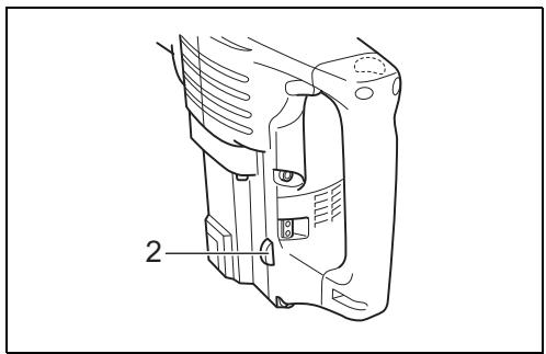
Indicator lamp (Fig. 3)
For HM1202C only
The green power-ON indicator lamp lights up when the tool is switched ON. If the indicator lamp is lit but the tool does not start, the carbon brushes may be worn out, or the electric circuit or the motor may be defective. If the indicator lamp does not light up and the tool does not start, the ON/OFF switch or the mains cord may be defective.
The red service indicator lamp lights up when the carbon brushes are nearly worn out to indicate that the tool needs servicing. After approx. 8 hours of use, the motor will automatically be shut off.
ASSEMBLY
CAUTION:
- Always be sure that the tool is switched off and unplugged before carrying out any work on the tool.
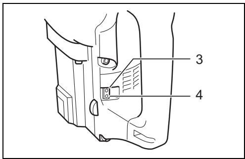
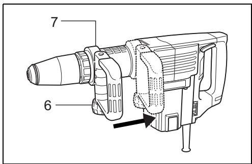
Side handle (auxiliary handle) (Fig. 4 & 5)
The side handle can be swung 360° on the vertical and secured at any desired position. It also secures at eight different positions back and forth on the horizontal. Just loosen the clamp nut to swing the side handle to a desired position. Then tighten the clamp nut securely.
The side handle also can be mounted in the rear groove. Loosen the clamp nut and widen the side handle base. Slide the side handle back to the rear groove and secure it with the clamp nut.
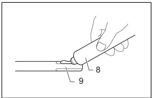
Installing or removing the bit (Fig. 6, 7 & 8)
Clean the bit shank and apply bit grease before installing the bit.
Insert the bit into the tool. Turn the bit and push it in until it engages.
If the bit cannot be pushed in, remove the bit. Pull the tool holder cover down a couple of times. Then insert the bit again. Turn the bit and push it in until it engages.
After installing, always make sure that the bit is securely held in place by trying to pull it out.
To remove the bit, pull the tool holder cover down all the way and pull the bit out.
Bit angle (Fig. 9)
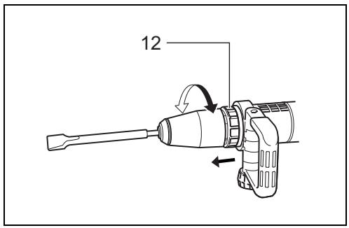
The bit can be secured at 12 different angles. To change the bit angle, slide the change ring forward, then turn the change ring to change the bit angle. At the desired angle, slide the change ring back to the original position. The bit will be secured in place.
NOTE:
- The change ring cannot turn when the bit is not installed on the tool.
OPERATION
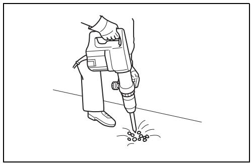
Chipping/Scaling/Demolition (Fig. 10)
Hold the tool firmly with both hands. Turn the tool on and apply slight pressure on the tool so that the tool will not bounce around, uncontrolled. Pressing very hard on the tool will not increase the efficiency.
MAINTENANCE
CAUTION:
- Always be sure that the tool is switched off and unplugged before attempting to perform inspection or maintenance.
- Never use gasoline, benzine, thinner, alcohol or the like. Discoloration, deformation or cracks may result.
Replacing carbon brushes (Fig. 11, 12 & 13)
When the resin insulating tip inside the carbon brush is exposed to contact the commutator, it will automatically shut off the motor. When this occurs, both carbon brushes should be replaced. Keep the carbon brushes clean and free to slip in the holders. Both carbon brushes should be replaced at the same time. Use only identical carbon brushes.
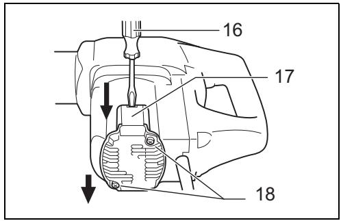
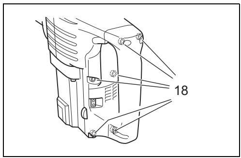
Remove the screws which secure the rear cover. Pry up the rear cover with a screwdriver and remove it.
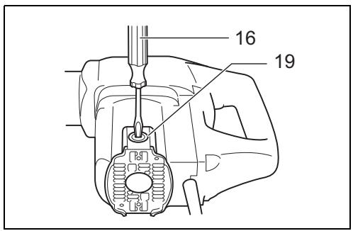
Use a screwdriver to remove the brush holder caps. Take out the worn carbon brushes, insert the new ones and secure the brush holder caps.
Lubrication (Fig. 14, 15 & 16)
This tool requires no hourly or daily lubrication because it has a grease-packed lubrication system. It should be relubricated after every 6 months of operation. Send the complete tool to Makita Authorized or Factory Service Center for this lubrication service. However, if circumstances require that you should lubricate it by yourself, proceed as follows.
Run the tool for several minutes to warm it up. Switch off and unplug the tool.
Loosen the six screws and remove the handle.
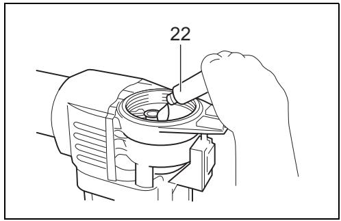
Remove the crank cap using a socket wrench. Rest the tool on the table with the bit end pointing upwards. This will allow the old grease to collect inside the crank housing.
Wipe out the old grease inside and replace with a fresh grease (30 g; 1 oz). Use only Makita genuine hammer grease (optional accessory). Filling with more than the specified amount of grease (approx. 30 g; 1 oz) can cause faulty hammering action or tool failure. Fill only with the specified amount of grease.
Reinstall the crank cap and tighten with the socket wrench.
CAUTION:
- Do not tighten the crank cap excessively. It is made of resin and is subject to breakage.
- Be careful not to damage the terminals or lead wires especially when wiping out the old grease or installing the handle.
To maintain product SAFETY and RELIABILITY, repairs, any other maintenance or adjustment should be performed by Makita Authorized Service Centers, always using Makita replacement parts.
ACCESSORIES
CAUTION:
- These accessories or attachments are recommended for use with your Makita tool specified in this manual. The use of any other accessories or attachments might present a risk of injury to persons. Only use accessory or attachment for its stated purpose.
If you need any assistance for more details regarding these accessories, ask your local Makita Service Center.
- Bull point (SDS-max)
• Cold chisel (SDS-max) - Scaling chisel (SDS-max)
- Clay spade (SDS-max)
- Rammer
- Safety goggles
- Hammer grease
- Plastic carrying case
ENG905-1
Noise
The typical A-weighted noise level determined according to EN60745:
Sound pressure level ( LpA ): 85 dB (A)
Sound power level ( LWA ): 99 dB (A)
Uncertainty (K): 2.6 dB (A)
Wear ear protection
Vibration
ENG900-1
The vibration total value (tri-axial vector sum) determined according to EN60745:
Work mode: chiseling
Vibration emission ( ah, CHeq ): 16.5 m/s 2
Uncertainty (K): 1.5 m/s²
ENG901-1
- The declared vibration emission value has been measured in accordance with the standard test method and may be used for comparing one tool with another.
- The declared vibration emission value may also be used in a preliminary assessment of exposure.
! WARNING:
- The vibration emission during actual use of the power tool can differ from the declared emission value depending on the ways in which the tool is used.
- Be sure to identify safety measures to protect the operator that are based on an estimation of exposure in the actual conditions of use (taking account of all parts of the operating cycle such as the times when the tool is switched off and when it is running idle in addition to the trigger time).
ENH212-11
For European countries only
EC Declaration of Conformity
We Makita Corporation as the responsible manufacturer declare that the following Makita machine(s):
Designation of Machine: Demolition Hammer
Model No./ Type: HM1202, HM1202C
Specifications: see "SPECIFICATIONS" table.
are of series production and
Conforms to the following European Directives:
2000/14/EC, 2006/42/EC
And are manufactured in accordance with the following standards or standardised documents:
EN60745
The technical documentation is kept by our authorized representative in Europe who is:
Makita International Europe Ltd.
Michigan Drive, Tongwell,
Milton Keynes, Bucks MK15 8JD, England
The conformity assessment procedure required by Directive 2000/14/EC was in Accordance with annex VIII.
Notified Body:
TÜV Rheinland LGA Products GmbH
Tillystraße 2
D-90431 Nürnberg
Identification number 0197
Measured Sound Power Level: 99 dB (A)
Guaranteed Sound Power Level: 101 dB (A)
10.8.2010

Tomoyasu Kato
Director
Makita Corporation
3-11-8, Sumiyoshi-cho,
Anjo, Aichi, 446-8502, JAPAN
Descriptif
2000/14/EC, 2006/42/EC
Michigan Drive, Tongwell,
Milton Keynes, Bucks MK15 8JD, Angleterre
3-11-8, Sumiyoshi-cho,
Anjo, Aichi, 446-8502, JAPAN
Übersicht
2000/14/EC, 2006/42/EC
Michigan Drive, Tongwell,
Milton Keynes, Bucks MK15 8JD, England
3-11-8, Sumiyoshi-cho,
Anjo, Aichi, 446-8502, JAPAN
Visione generale
Modello No./Tipo: HM1202, HM1202C
Michigan Drive, Tongwell,
Milton Keynes, Bucks MK15 8JD, England
3-11-8, Sumiyoshi-cho,
Anjo, Aichi, 446-8502, JAPAN
Modelnr./Type: HM1202, HM1202C
Technische gegevens: zie de tabel "TECHNISCHE GEGEVENS".
2000/14/EC, 2006/42/EC
Michigan Drive, Tongwell,
Milton Keynes, Bucks MK15 8JD, Engeland
3-11-8, Sumiyoshi-cho,
Anjo, Aichi, 446-8502, JAPAN
2000/14/EC, 2006/42/EC
Michigan Drive, Tongwell,
Milton Keynes, Bucks MK15 8JD, Inglaterra
3-11-8, Sumiyoshi-cho,
Anjo, Aichi, 446-8502, JAPAN
Explicação geral
2000/14/EC, 2006/42/EC
Michigan Drive, Tongwell,
Milton Keynes, Bucks MK15 8JD, Inglaterra
3-11-8, Sumiyoshi-cho,
Anjo, Aichi, 446-8502, JAPAN
2000/14/EC, 2006/42/EC
Michigan Drive, Tongwell,
Milton Keynes, Bucks MK15 8JD, England
3-11-8, Sumiyoshi-cho,
Anjo, Aichi, 446-8502, JAPAN
2000/14/EK, 2006/42/EK
Michigan Drive, Tongwell,
Milton Keynes, Bucks MK15 8JD, England (Aγγλία)
3-11-8, Sumiyoshi-cho,
Anjo, Aichi, 446-8502, JAPAN
Makita Corporation
Anjo, Aichi, Japan
- INTENDED USE
- POWER SUPPLY
- FOR PUBLIC LOW-VOLTAGE DISTRIBUTION SYSTEMS OF BETWEEN 220 V AND 250 V
- GENERAL POWER TOOL SAFETY WARNINGS
- HAMMER SAFETY WARNINGS
- SAVE THESE INSTRUCTIONS
- WARNING
- FUNCTIONAL DESCRIPTION
- CAUTION
- SWITCH ACTION (FIG. 1)
- SPEED CHANGE (FIG. 2)
- FOR HM1202C ONLY
- INDICATOR LAMP (FIG. 3)
- ASSEMBLY
- SIDE HANDLE (AUXILIARY HANDLE) (FIG. 4 & 5)
- INSTALLING OR REMOVING THE BIT (FIG. 6, 7 & 8)
- BIT ANGLE (FIG. 9)
- NOTE
- OPERATION
- CHIPPING/SCALING/DEMOLITION (FIG. 10)
- MAINTENANCE
- REPLACING CARBON BRUSHES (FIG. 11, 12 & 13)
- LUBRICATION (FIG. 14, 15 & 16)
- ACCESSORIES
- NOISE
- VIBRATION
- FOR EUROPEAN COUNTRIES ONLY
- EC DECLARATION OF CONFORMITY
- MAKITA CORPORATION
Brand : MAKITA
Model : HM1202
Category : Jackhammer