
HR2601 - Jackhammer MAKITA - Free user manual and instructions
Find the device manual for free HR2601 MAKITA in PDF.
| Product Type | Rotary Hammer |
| Brand | MAKITA |
| Model | HR2601 |
| Drilling Capacity (Concrete) | 26 mm |
| Drilling Capacity (Steel) | 13 mm |
| Drilling Capacity (Wood) | 32 mm |
| Drilling Capacity (Core Bit) | 68 mm |
| Drilling Capacity (Diamond Core Bit, Dry) | 80 mm |
| No Load Speed | 0 - 1,200 min⁻¹ |
| Blows per Minute | 0 - 4,600 min⁻¹ |
| Overall Length | 385 mm |
| Net Weight (EPTA 01/2003) | 2.9 kg |
| Safety Class | Double Insulated (Class II) |
| Power Supply | Single-phase, voltage as per nameplate |
| Chuck Type | SDS-plus Quick-Change |
| Operating Modes | Rotation with Hammering, Rotation without Hammering, Hammering without Rotation |
| Main Functions | Drilling, Chiseling, Scaling, Demolition |
| Maintenance and Cleaning | Disconnect before maintenance; clean with a dry cloth; do not use solvents; have it serviced by an authorized Makita service center |
| Safety | Mandatory use of hearing protection, safety glasses, dust mask, and helmet; use the side handle; check screws before use |
| Spare Parts and Repairability | Use only Makita genuine spare parts; repair by authorized service center |
| General Information | Manual available in multiple languages; weight according to EPTA 01/2003 |
Frequently Asked Questions - HR2601 MAKITA
User questions about HR2601 MAKITA
0 question about this device. Answer the ones you know or ask your own.
Ask a new question about this device
Download the instructions for your Jackhammer in PDF format for free! Find your manual HR2601 - MAKITA and take your electronic device back in hand. On this page are published all the documents necessary for the use of your device. HR2601 by MAKITA.
USER MANUAL HR2601 MAKITA
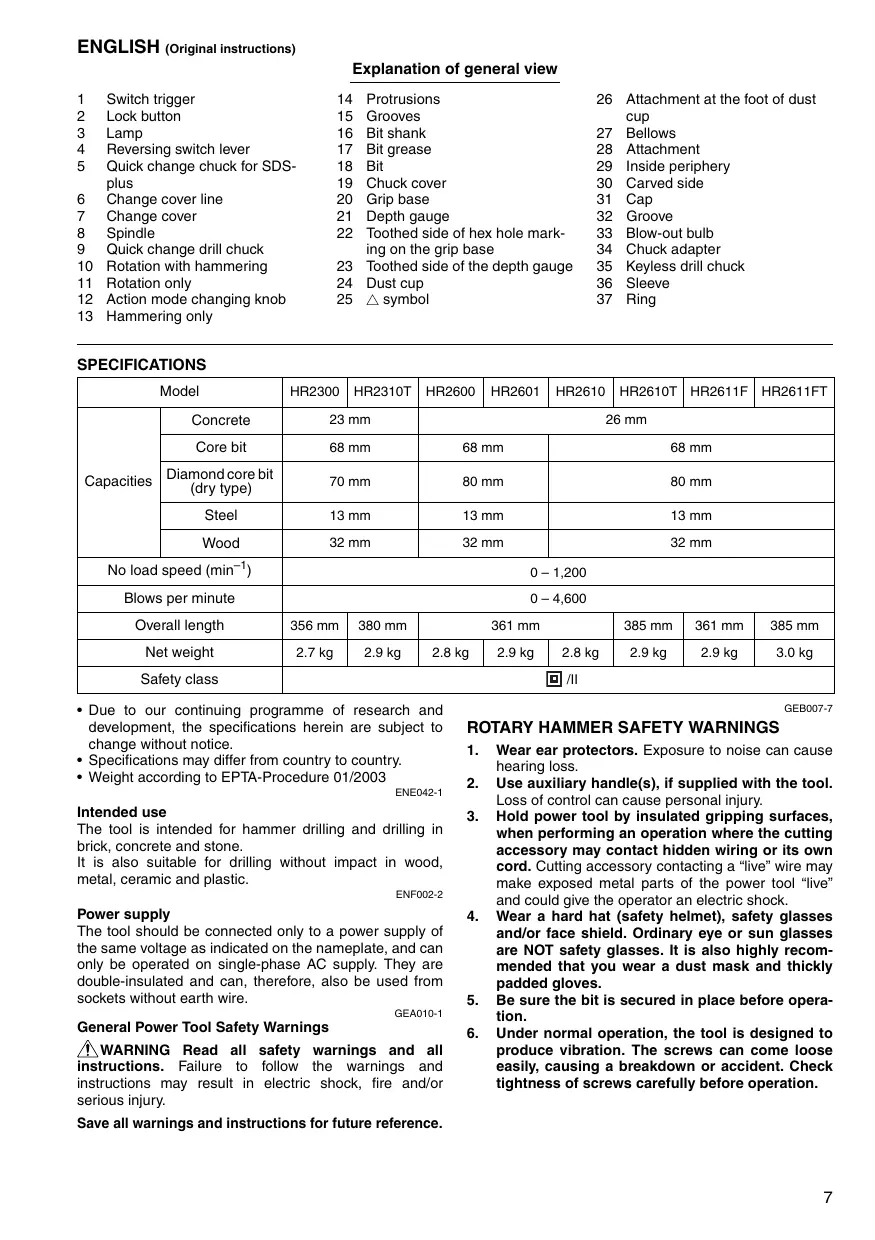
Explanation of general view
| 1 | Switch trigger | 14 | Protrusions | 26 | Attachment at the foot of dust cup |
| 2 | Lock button | 15 | Grooves | ||
| 3 | Lamp | 16 | Bit shank | 27 | Bellows |
| 4 | Reversing switch lever | 17 | Bit grease | 28 | Attachment |
| 5 | Quick change chuck for SDS-plus | 18 | Bit | 29 | Inside periphery |
| 6 | Change cover line | 19 | Chuck cover | 30 | Carved side |
| 7 | Change cover | 20 | Grip base | 31 | Cap |
| 8 | Spindle | 21 | Depth gauge | 32 | Groove |
| 9 | Quick change drill chuck | Toothed side of hex hole marking on the grip base | 33 | Blow-out bulb | |
| 10 | Rotation with hammering | 23 | Toothed side of the depth gauge | 34 | Chuck adapter |
| 11 | Rotation only | 24 | Dust cup | 35 | Keyless drill chuck |
| 12 | Action mode changing knob | 25 | △ symbol | 36 | Sleeve |
SPECIFICATIONS
| Model | HR2300 | HR2310T | HR2600 | HR2601 | HR2610 | HR2610T | HR2611F | HR2611FT | |
| Capacities | Concrete | 23 mm | 26 mm | ||||||
| Core bit | 68 mm | 68 mm | 68 mm | ||||||
| Diamond core bit (dry type) | 70 mm | 80 mm | 80 mm | ||||||
| Steel | 13 mm | 13 mm | 13 mm | ||||||
| Wood | 32 mm | 32 mm | 32 mm | ||||||
| No load speed (min-1) | 0-1,200 | ||||||||
| Blows per minute | 0-4,600 | ||||||||
| Overall length | 356 mm | 380 mm | 361 mm | 385 mm | 361 mm | 385 mm | |||
| Net weight | 2.7 kg | 2.9 kg | 2.8 kg | 2.9 kg | 2.8 kg | 2.9 kg | 2.9 kg | 3.0 kg | |
| Safety class | ☐/II | ||||||||
- Due to our continuing programme of research and development, the specifications herein are subject to change without notice.
- Specifications may differ from country to country.
Weight according to EPTA-Procedure 01/2003
ENE042-1
Intended use
The tool is intended for hammer drilling and drilling in brick, concrete and stone.
It is also suitable for drilling without impact in wood, metal, ceramic and plastic.
ENF002-2
Power supply
The tool should be connected only to a power supply of the same voltage as indicated on the nameplate, and can only be operated on single-phase AC supply. They are double-insulated and can, therefore, also be used from sockets without earth wire.
GEA010-1
General Power Tool SafetyWarnings
WARNING Read all safety warnings and all instructions. Failure to follow the warnings and instructions may result in electric shock, fire and/or serious injury.
Save all warnings and instructions for future reference.
GEB007-7
ROTARY HAMMER SAFETY WARNINGS
- Wear ear protectors. Exposure to noise can cause hearing loss.
- Use auxiliary handle(s), if supplied with the tool. Loss of control can cause personal injury.
- Hold power tool by insulated gripping surfaces, when performing an operation where the cutting accessory may contact hidden wiring or its own cord. Cutting accessory contacting a "live" wire may make exposed metal parts of the power tool "live" and could give the operator an electric shock.
- Wear a hard hat (safety helmet), safety glasses and/or face shield. Ordinary eye or sun glasses are NOT safety glasses. It is also highly recommended that you wear a dust mask and thickly padded gloves.
- Be sure the bit is secured in place before operation.
-
Under normal operation, the tool is designed to produce vibration. The screws can come loose easily, causing a breakdown or accident. Check tightness of screws carefully before operation.
-
In cold weather or when the tool has not been used for a long time, let the tool warm up for a while by operating it under no load. This will loosen up the lubrication. Without proper warm up, hammering operation is difficult.
- Always be sure you have a firm footing. Be sure no one is below when using the tool in high locations.
- Hold the tool firmly with both hands.
- Keep hands away from moving parts.
- Do not leave the tool running. Operate the tool only when hand-held.
- Do not point the tool at any one in the area when operating. The bit could fly out and injure someone seriously.
- Do not touch the bit or parts close to the bit immediately after operation; they may be extremely hot and could burn your skin.
- Some material contains chemicals which may be toxic. Take caution to prevent dust inhalation and skin contact. Follow material supplier safety data.
SAVE THESE INSTRUCTIONS.
WARNING:
DO NOT let comfort or familiarity with product (gained from repeated use) replace strict adherence to safety rules for the subject product. MISUSE or failure to follow the safety rules stated in this instruction manual may cause serious personal injury.
FUNCTIONAL DESCRIPTION
CAUTION:
Always be sure that the tool is switched off and unplugged before adjusting or checking function on the tool.
Switch action (Fig. 1)
CAUTION:
- Before plugging in the tool, always check to see that the switch trigger actuates properly and returns to the "OFF" position when released.
To start the tool, simply pull the switch trigger. Tool speed is increased by increasing pressure on the switch trigger. Release the switch trigger to stop. For continuous operation, pull the switch trigger and then push in the lock button and then release the switch trigger. To stop the tool from the locked position, pull the switch trigger fully, then release it.
Lighting up the lamps (Fig. 2)
For Models HR2611F, HR2611FT
CAUTION:
- Do not look in the light or see the source of light directly.
To turn on the lamp, pull the trigger. Release the trigger to turn it off.
NOTE:
- Use a dry cloth to wipe the dirt off the lens of lamp. Be careful not to scratch the lens of lamp, or it may lower the illumination.
- Do not use thinner or gasoline to clean the lamp. Such solvents may damage it.
Reversing switch action (Fig. 3)
CAUTION:
- Always check the direction of rotation before operation.
- Use the reversing switch only after the tool comes to a complete stop. Changing the direction of rotation before the tool stops may damage the tool.
- If the switch trigger can not be depressed, check to see that the reversing switch is fully set to position (A side) or (B side).
This tool has a reversing switch to change the direction of rotation. Move the reversing switch lever to the position (A side) for clockwise rotation or to the position (B side) for counterclockwise rotation.
Changing the quick change chuck for SDS-plus
For Models HR2310T, HR2610T, HR2611FT
The quick change chuck for SDS-plus can be easily exchanged for the quick change drill chuck.
Removing the quick change chuck for SDS-plus (Fig. 4)
CAUTION:
- Before removing the quick change chuck for SDS-plus, always remove the bit.
Grasp the change cover of the quick change chuck for SDS-plus and turn in the direction of the arrow until the change cover line moves from the symbol to the symbol. Pull forcefully in the direction of the arrow.
Attaching the quick change drill chuck (Fig. 5)
Check the line of the quick change drill chuck shows the symbol. Grasp the change cover of the quick change drill chuck and set the line to the symbol.
Place the quick change drill chuck on the spindle of the tool.
Grasp the change cover of the quick change drill chuck and turn the change cover line to the symbol until a click can clearly be heard.
Selection action mode (Fig. 6)
For Models HR2300, HR2600, HR2601
This tool employs an action mode changing knob. Select one of the two modes suitable for your work needs by using this knob.
For rotation only, turn the knob so that the arrow on the knob points toward the symbol on the tool body.
For rotation with hammering, turn the knob so that the arrow on the knob points toward the symbol on the tool body.
CAUTION:
- Always set the knob fully to your desired mode symbol. If you operate the tool with the knob positioned halfway between the mode symbols, the tool may be damaged.
- Use the knob after the tool comes to a complete stop.
For Models HR2310T, HR2610, HR2610T, HR2611F, HR2611FT
Rotation with hammering (Fig. 7)
For drilling in concrete, masonry, etc., rotate the action mode changing knob to the symbol. Use a tungsten-carbide tipped bit.
Rotation only (Fig. 8)
For drilling in wood, metal or plastic materials, rotate the action mode changing knob to the symbol. Use a twist drill bit or wood bit.
Hammering only (Fig. 9)
For chipping, scaling or demolition operations, rotate the action mode changing knob to the symbol. Use a bull point, cold chisel, scaling chisel, etc.
CAUTION:
- Do not rotate the action mode changing knob when the tool is running under load. The tool will be damaged.
- To avoid rapid wear on the mode change mechanism, be sure that the action mode changing knob is always positively located in one of the three action mode positions.
- When changing from the symbol mode to the symbol mode, the action mode changing knob may no longer move in the symbol position. At this time, turn the tool on or turn the chuck by hand in the symbol position and then rotate the action mode changing knob. Forcing the action mode changing knob may cause tool damage.
Torque limiter
The torque limiter will actuate when a certain torque level is reached. The motor will disengage from the output shaft. When this happens, the bit will stop turning.
CAUTION:
- As soon as the torque limiter actuates, switch off the tool immediately. This will help prevent premature wear of the tool.
- Bits such as hole saw, which tend to pinch or catch easily in the hole, are not appropriate for this tool. This is because they will cause the torque limiter to actuate too frequently.
ASSEMBLY
CAUTION:
- Always be sure that the tool is switched off and unplugged before carrying out any work on the tool.
Side grip (auxiliary handle) (Fig. 10)
CAUTION:
Always use the side grip to ensure operating safety.
Install the side grip so that the protrusions on the grip fit in between the grooves on the tool barrel. Then tighten the grip by turning clockwise at the desired position. It may be swung 360° so as to be secured at any position.
Bit grease
Coat the bit shank head beforehand with a small amount of bit grease (about 0.5 - 1g ).
This chuck lubrication assures smooth action and longer service life.
Installing or removing the bit
Clean the bit shank and apply bit grease before installing the bit. (Fig. 11)
Insert the bit into the tool. Turn the bit and push it in until it engages. (Fig. 12)
After installing, always make sure that the bit is securely held in place by trying to pull it out.
To remove the bit, pull the chuck cover down all the way and pull the bit out. (Fig. 13)
Bit angle (when chipping, scaling or demolishing)
For Models HR2310T, HR2610, HR2610T, HR2611F, HR2611FT
The bit can be secured at the desired angle. To change the bit angle, rotate the action mode changing knob to the O symbol. Turn the bit to the desired angle. (Fig. 14) Rotate the action mode changing knob to the symbol. (Fig. 15)
Then make sure that the bit is securely held in place by turning it slightly.
Depth gauge
The depth gauge is convenient for drilling holes of uniform depth. (Fig. 16)
Press the lock button on the grip base in the direction of arrow shown in the figure and with the lock button being pressed insert the depth gauge into the hex. hole in the grip base. (Fig. 17)
At this time, the depth gauge needs to be inserted so that its toothed side is directed to the toothed side of hex hole marking on the grip base as shown in Fig. 18.
Adjust the depth gauge to the desired depth by moving it back and forth while pressing the lock button. After the adjustment, release the lock button to lock the depth gauge. (Fig. 19)
NOTE:
- Inserting the depth gauge with its toothed side not directed to the toothed side of hex hole marking on the grip base as shown in the figure does not allow the depth gauge to be locked.
Dust cup (Fig. 20)
Use the dust cup to prevent dust from falling over the tool and on yourself when performing overhead drilling operations. Attach the dust cup to the bit as shown in Fig. 20. The size of bits which the dust cup can be attached to is as follows.
| Bit diameter | |
| Dust cup 5 | 6 mm – 14.5 mm |
| Dust cup 9 | 12 mm – 16 mm |
006406
There is another type of dust cup (accessory) which helps you prevent dust from falling over the tool and on yourself when performing overhead drilling operations.
Installing or removing the dust cup
Before installing the dust cup, remove the bit from the tool if installed on the tool. Install the dust cup (accessory) on the tool so that the symbol on the dust cup is aligned with the grooves in the tool. (Fig. 21)
To remove the dust cup, pull the chuck cover in the direction as shown in Fig. 22 and with the chuck cover pulled take the bit out of the tool.
And then grab the attachment at the foot of dust cup and take it out. (Fig. 23)
NOTE:
- When installing or removing the dust cup, the cap may come off the dust cup. At that time, proceed as follows. Remove the bellows from the attachment and fit the cap from the side shown in the figure with its carved side facing upward so that the groove in the cap fits in the inside periphery of the attachment. Finally, mount the bellows that has been removed. (Fig. 24, 25 & 26)
NOTE:
- If you connect a vacuum cleaner to your hammer, cleaner operations can be performed. Dust cap needs to be removed from the dust cup before the connection. (Fig. 27)
OPERATION
Always use the side grip (auxiliary handle) and firmly hold the tool by both side grip and switch handle during operations.
Hammer drilling operation (Fig. 28)
Set the action mode changing knob to the symbol.
Position the bit at the desired location for the hole, then pull the switch trigger. Do not force the tool. Light pressure gives best results. Keep the tool in position and prevent it from slipping away from the hole.
Do not apply more pressure when the hole becomes clogged with chips or particles. Instead, run the tool at an idle, then remove the bit partially from the hole. By repeating this several times, the hole will be cleaned out and normal drilling may be resumed.
Set the action mode changing knob to the symbol.
CAUTION:
- There is tremendous and sudden twisting force exerted on the tool/bit at the time of hole break-through, when the hole becomes clogged with chips and particles, or when striking reinforcing rods embedded in the concrete. Always use the side grip (auxiliary handle) and firmly hold the tool by both side grip and switch handle during operations. Failure to do so may result in the loss of control of the tool and potentially severe injury.
NOTE:
- Eccentricity in the bit rotation may occur while operating the tool with no load. The tool automatically centers itself during operation. This does not affect the drilling precision.
Blow-out bulb (optional accessory) (Fig. 29)
After drilling the hole, use the blow-out bulb to clean the dust out of the hole.
Chipping/Scaling/Demolition
For Models HR2310T, HR2610, HR2610T, HR2611F, HR2611FT
Set the action mode changing knob to the symbol. Hold the tool firmly with both hands. Turn the tool on and apply slight pressure on the tool so that the tool will not bounce around, uncontrolled. Pressing very hard on the tool will not increase the efficiency. (Fig. 30)
Drilling in wood or metal
For Models HR2300, HR2600, HR2601, HR2610, HR2611F
Use the optional drill chuck assembly. When installing it, refer to "Installing or removing the bit" described on the previous page. (Fig. 31)
For Models HR2310T, HR2610T, HR2611FT
Use the quick change drill chuck as standard equipment. When installing it, refer to "changing the quick change chuck for SDS-plus" described on the previous page. (Fig. 32 & 33)
Hold the ring and turn the sleeve counterclockwise to open the chuck jaws. Place the bit in the chuck as far as it will go. Hold the ring firmly and turn the sleeve clockwise to tighten the chuck. To remove the bit, hold the ring and turn the sleeve counterclockwise. (Fig. 34)
Set the action mode changing knob to the symbol.
You can drill up to 13 mm diameter in metal and up to 32 mm diameter in wood.
CAUTION:
- Never use "rotation with hammering" when the quick change drill chuck is installed on the tool. The quick change drill chuck may be damaged.
Also, the drill chuck will come off when reversing the tool.
- Pressing excessively on the tool will not speed up the drilling. In fact, this excessive pressure will only serve to damage the tip of your bit, decrease the tool performance and shorten the service life of the tool.
- There is a tremendous twisting force exerted on the tool/bit at the time of hole breakthrough. Hold the tool firmly and exert care when the bit begins to break through the workpiece.
- A stuck bit can be removed simply by setting the reversing switch to reverse rotation in order to back out. However, the tool may back out abruptly if you do not hold it firmly.
- Always secure small workpieces in a vise or similar hold-down device.
Diamond core drilling
When performing diamond core drilling operations, always set the change lever to the position to use "rotation only" action.
CAUTION:
- If performing diamond core drilling operations using "rotation with hammering" action, the diamond core bit may be damaged.
Operation when using the dust cup (accessory) (Fig. 35)
Operate the tool with the dust cup against the ceiling surface.
NOTE:
- The dust cup (accessory) is intended only for drilling in the ceramic workpiece such as concrete and mortar. Do not use the tool with the dust cup when drilling in metal or similar. Using the dust cup for drilling in the metal may damage the dust cup due to the heat produced by small metal dust or similar.
- Empty the dust cup before removing a drill bit.
- When using the dust cup, make sure that the dust cap is mounted on it securely.
MAINTENANCE
CAUTION:
Always be sure that the tool is switched off and unplugged before attempting to perform inspection or maintenance.
- Never use gasoline, benzine, thinner, alcohol or the like. Discoloration, deformation or cracks may result.
To maintain product SAFETY and RELIABILITY, repairs, carbon brush inspection and replacement, any other maintenance or adjustment should be performed by Makita Authorized Service Centers, always using Makita replacement parts.
OPTIONAL ACCESSORIES
CAUTION:
- These accessories or attachments are recommended for use with your Makita tool specified in this manual. The use of any other accessories or attachments might present a risk of injury to persons. Only use accessory or attachment for its stated purpose.
If you need any assistance for more details regarding these accessories, ask your local Makita Service Center.
- SDS-Plus Carbide-tipped bits
Core bit - Bull point
Diamond core bit
Cold chisel - Scaling chisel
Grooving chisel - Drill chuck assembly
- Drill chuck S13
- Chuck adapter
- Chuck key S13
- Bit grease
- Side grip
- Depth gauge
- Blow-out bulb
- Dust cup
- Dust extractor attachment
- Safety goggles
- Plastic carrying case
Keyless drill chuck
NOTE
- Some items in the list may be included in the tool package as standard accessories. They may differ from country to country.
ENG905-1
Noise
The typical A-weighted noise level determined according to EN60745:
Model HR2300, HR2601, HR2611F, HR2611FT
Sound pressure level (LpA) : 90 dB (A)
Sound power level (LWA) : 101 dB (A)
Uncertainty (K): 3 dB (A)
Model HR2310T, HR2600, HR2610, HR2610T
Sound pressure level (LpA) : 91 dB (A)
Sound power level (LWA) : 102 dB (A)
Uncertainty (K): 3 dB (A)
Wear ear protection
Vibration
The vibration total value (tri-axial vector sum) determined according to EN60745:
Model HR2300, HR2600
Work mode: hammer drilling into concrete
Vibration emission (ah,HD) : 15.5 m/s²
Uncertainty (K): 1.5 m/s²
Work mode: drilling into metal
Vibration emission (ah,D) : 2.5 m/s²
Uncertainty (K): 1.5 m/s²
Model HR2310T
Work mode: hammer drilling into concrete
Vibration emission (ah, HD) : 15.5 m/s²
Uncertainty (K): 1.5 m/s²
Work mode: chiselling function with side grip
Vibration emission (ah,CHeq) : 10.5 m / s2 Uncertainty (K): 1.5 m / s2
Work mode: drilling into metal
Vibration emission (ah,D) : 2.5 m/s² or less
Uncertainty (K): 1.5 m/s²
Model HR2601
Work mode: hammer drilling into concrete
Vibration emission (ah, HD) : 12.0 m/s²
Uncertainty (K): 1.5 m/s²
Work mode: drilling into metal
Vibration emission (ah,D) : 2.5 m/s² or less
Uncertainty (K): 1.5 m/s²
Model HR2610
Work mode: hammer drilling into concrete
Vibration emission (ah,HD) : 15.5 m/s²
Uncertainty (K): 1.5 m/s²
Work mode: chiselling function with side grip Vibration emission (ah,CHeq) : 9.5 m/s2 Uncertainty (K): 1.5m / s2
Work mode: drilling into metal
Vibration emission (ah,D) : 2.5 m / s2 Uncertainty (K): 1.5 m / s2
Model HR2610T
Work mode: hammer drilling into concrete
Vibration emission (ah, HD) : 15.0 m/s²
Uncertainty (K): 1.5 m/s²
Work mode: chiselling function with side grip
Vibration emission (ah,CHeq) : 9.5 m/s²
Uncertainty (K): 1.5 m/s²
Work mode: drilling into metal
Vibration emission (ah,D) : 2.5 m/s² or less
Uncertainty (K): 1.5 m/s²
Model HR2611F
Work mode: hammer drilling into concrete
Vibration emission (ah,HD) : 12.0 m / s2 Uncertainty (K): 1.5 m / s2
Work mode: chiselling function with side grip Vibration emission (ah,CHeq) .. 9.0 m / s2 Uncertainty (K): 1.5m / s2
Work mode: drilling into metal
Vibration emission (ah,D) : 2.5 m/s² or less
Uncertainty (K): 1.5 m/s²
Model HR2611FT
Work mode: hammer drilling into concrete
Vibration emission (ah,HD) .. 11.5 m / s2
Uncertainty (K): 1.5m / s2
Work mode: chiselling function with side grip
Vibration emission (ah,CHeq) .. 8.5 m / s2
Uncertainty (K): 1.5m / s2
Work mode: drilling into metal
Vibration emission (ah,D) : 2.5m / s2 or less
Uncertainty (K): 1.5m / s2
ENG901-1
- The declared vibration emission value has been measured in accordance with the standard test method and may be used for comparing one tool with another.
- The declared vibration emission value may also be used in a preliminary assessment of exposure.
WARNING:
- The vibration emission during actual use of the power tool can differ from the declared emission value depending on the ways in which the tool is used.
- Be sure to identify safety measures to protect the operator that are based on an estimation of exposure in the actual conditions of use (taking account of all parts of the operating cycle such as the times when the tool is switched off and when it is running idle in addition to the trigger time).
ENH101-15
For European countries only
EC Declaration of Conformity
We Makita Corporation as the responsible manufacturer declare that the following Makita machine(s):
Designation of Machine: Rotary Hammer
Model No./ Type: HR2300, HR2310T, HR2600, HR2601 are of series production and
Conforms to the following European Directives:
2006/42/EC
And are manufactured in accordance with the following standards or standardised documents:
EN60745
The technical documentation is kept by our authorized representative in Europe who is:
Makita International Europe Ltd.
Michigan Drive, Tongwell,
Milton Keynes, Bucks MK15 8JD, England
13.7.2009

Tomoyasu Kato
Director
Makita Corporation
3-11-8, Sumiyoshi-cho,
Anjo, Aichi, 446-8502, JAPAN
For European countries only
EC Declaration of Conformity
We Makita Corporation as the responsible manufacturer declare that the following Makita machine(s):
Designation of Machine: Combination Hammer
Model No./ Type: HR2610, HR2610T, HR2611F, HR2611FT
are of series production and
Conforms to the following European Directives:
2006/42/EC
And are manufactured in accordance with the following standards or standardised documents:
EN60745
The technical documentation is kept by our authorized representative in Europe who is:
Makita International Europe Ltd.
Michigan Drive, Tongwell,
Milton Keynes, Bucks MK15 8JD, England
13.7.2009

Tomoyasu Kato
Director
Makita Corporation
3-11-8, Sumiyoshi-cho,
Anjo, Aichi, 446-8502, JAPAN
Descriptif
Rotation sans percussion (Fig. 8)
ACCESSIONS EN OPTION
ATTENTION:
Michigan Drive, Tongwell,
Milton Keynes, Bucks MK15 8JD, Angleterre
13.7.2009

Tomoyasu Kato
Director
Makita Corporation
3-11-8, Sumiyoshi-cho,
Anjo, Aichi, 446-8502, JAPAN
Michigan Drive, Tongwell,
Milton Keynes, Bucks MK15 8JD, Angleterre
13.7.2009

Tomoyasu Kato
Director
Makita Corporation
3-11-8, Sumiyoshi-cho,
Anjo, Aichi, 446-8502, JAPAN
Ubersicht
Michigan Drive, Tongwell,
Milton Keynes, Bucks MK15 8JD, England
13.7.2009

Tomoyasu Kato Direktor
Makita Corporation
3-11-8, Sumiyoshi-cho,
Anjo, Aichi, 446-8502, JAPAN
Michigan Drive, Tongwell,
Milton Keynes, Bucks MK15 8JD, England
13.7.2009

Tomoyasu Kato
Direktor
Makita Corporation
3-11-8, Sumiyoshi-cho,
Anjo, Aichi, 446-8502, JAPAN
Nome delle parti
Michigan Drive, Tongwell,
Milton Keynes, Bucks MK15 8JD, England
13.7.2009

Tomoyasu Kato
Aministratore
Makita Corporation
3-11-8, Sumiyoshi-cho,
Anjo, Aichi, 446-8502, JAPAN
Michigan Drive, Tongwell,
Milton Keynes, Bucks MK15 8JD, England
13.7.2009

Tomoyasu Kato
Aministratore
Makita Corporation
3-11-8, Sumiyoshi-cho,
Anjo, Aichi, 446-8502, JAPAN
OPTIONELE ACCESSOIRES
letOP:
Michigan Drive, Tongwell,
Milton Keynes, Bucks MK15 8JD, England
13.7.2009

Tomoyasu Kato
Director
Makita Corporation
3-11-8, Sumiyoshi-cho,
Anjo,Aichi,446-8502,JAPAN
Michigan Drive, Tongwell,
Milton Keynes, Bucks MK15 8JD, England
13.7.2009

Tomoyasu Kato
Director
Makita Corporation
3-11-8, Sumiyoshi-cho,
Anjo, Aichi, 446-8502, JAPAN
Michigan Drive, Tongwell,
Milton Keynes, Bucks MK15 8JD, Inglaterra
13.7.2009

Tomoyasu Kato
Director
Makita Corporation
3-11-8, Sumiyoshi-cho,
Anjo,Aichi,446-8502,JAPAN
Michigan Drive, Tongwell,
Milton Keynes, Bucks MK15 8JD, Inglaterra
13.7.2009

Tomoyasu Kato
Director
Makita Corporation
3-11-8, Sumiyoshi-cho,
Anjo, Aichi, 446-8502, JAPAN
Explicaçao geral
Michigan Drive, Tongwell,
Milton Keynes, Bucks MK15 8JD, Inglaterra
13.7.2009

Tomoyasu Kato
Director
Makita Corporation
3-11-8, Sumiyoshi-cho,
Anjo, Aichi, 446-8502, JAPAN
Michigan Drive, Tongwell,
Milton Keynes, Bucks MK15 8JD, Inglaterra
13.7.2009

Tomoyasu Kato
Director
Makita Corporation
3-11-8, Sumiyoshi-cho,
Anjo, Aichi, 446-8502, JAPAN
Michigan Drive, Tongwell,
Milton Keynes, Bucks MK15 8JD, England
13.7.2009

Tomoyasu Kato
Direktør
Makita Corporation
3-11-8, Sumiyoshi-cho,
Anjo,Aichi,446-8502,JAPAN
Kun for lande i Europa
Michigan Drive, Tongwell,
Milton Keynes, Bucks MK15 8JD, England
13.7.2009

Tomoyasu Kato
Direktør
Makita Corporation
3-11-8, Sumiyoshi-cho,
Anjo, Aichi, 446-8502, JAPAN
Iepiypaqni yeviknc aioyns
HME IΩH
Eav ouvdeote nAekptikn oKouna oTo ophiu, nOpneite va ekteleste epyaicKaohapiou. Anaiteial aphipeon Tou mawatoc okovcn ano to kalmu maokovnc, npiv ano tn ouvdoen.(Eik.27)
AEITOYPTFIA
Na xpnouoieite nvtn eupkn λ β (bonnntkna) kai va kpatate otaBepa to evyaiao ano nvtneuapkn na kn tna bn diakontn kat a nvt ektean twv evyaowv.
Aeitoupyia kpoouotiknC diatpnoC (EIK.28)
TupioTe to koumi aalaync tou tponou aeitoupyiac oTo ouboLo.
Tonoetne TnV aun oTo enuunTo onueio yia diavoi nnc onnc, stn ouxeia tpaBnte Tn okavdaan Evpyooinoc. Mny aokeite duvaun oTo epyaleio. H uipni neon exei wc anoteloeqa Btota anoteleqmuata. Kpatne To epyaio ot N theou kai emodote to va Ephiyei ano tnv onn.
Mny aokte Ie yalutepn nio, otav n omnpaouiaei eipaaen ano opaouma t aojatiod. Avti autou, theoTe to epyaiaio ae leitoupyia palevnt kai onuovexia tpaBnEe eaapca tyn aixm EeW ano Tnv onn.Eav enavaaBete to idio apkertc opec, no onn eAeuOepwetai ano ta opaouata kai npoeite va ouvexioe T ney epyaia diavoiIc.
Tupot To koumi aalaync Tou tponou aeitoupyiac oTo ouboLo
PIPOZOXH:
To epyaaleio/aixun uphiatai faovikn kai oxupn duvam npiotpooic n toy mou diepxetai ano tvn oto alko, otav n onn napouiae i emuapEn tpoauqata kai oomegaia dnt ovuvantoei beyec evioxuoc naktwuevec oto okupobsema. Na xnpauooteite na vta tn paeupki n (bonthetaikn la) kai va kpatate otaeopa to epyaieo ano tn paeupkni lah kai tn laib diakontn kat ayn EKTLEON TW epyaow. H n oumuopfwn evexetai va exi wc anoteloeqa tvn anwlaeia elxyou tou epyaoleiou kai tvn evexoevn npoknon oobapou tpaumatou.
ZHMEIΩΣH:
Evoextalva napatnpn0e EKKeVpIKoTeta otyn kivontnaixnOtav to epyaiaio Bpioketai o aepyn aeitoupyia.To epyaiaio Kevtpapetai autouata ondiapkeia nC aeitoupyiac.Auto 8ev ennpaezi Tny akpiieia diatpono.
Tia Eupwnaikec xwpec movo
Anwun∑uipφωncEK
H Makita Corporation, wC unEubuvoc KaatakeuaTc, 0nawvei oTo/ta akolouo(a) mXavma(ta) TcMakita:
Xapaktnpiouc mxavnauo; Tepiatpofo K oaphi Ap. oovTeou/ Tucoc: HR2300, HR2310T, HR2600, HR2601
Michigan Drive, Tongwell,
Milton Keynes, Bucks MK15 8JD, England (Ayylambda)
13.7.2009

Tomoyasu Kato
△ieuθuvntc
Makita Corporation
3-11-8, Sumiyoshi-cho,
Anjo, Aichi, 446-8502, JAPAN
Tia Eupwnaikec xwpce movo
△λωση Σμιρφωσεκ EK
H Makita Corporation, wC unEubuvoc kataokEuagTc, 0nAovc oAkOauo(a) mAnvma(ta) nC Makita:
XapaKtnpiouc mXavnmuToc; ΣΦupi ouvδuaouAp. oovTeλou/TuOc: HR2610, HR2610T, HR2611F, HR2611FT
Michigan Drive, Tongwell,
Milton Keynes, Bucks MK15 8JD, England (Ayylambda)
13.7.2009

Tomoyasu Kato
△ieuθuvtns
Makita Corporation
3-11-8, Sumiyoshi-cho,
Anjo, Aichi, 446-8502, JAPAN
Makita Corporation
Anjo, Aichi, Japan
- INTENDED USE
- POWER SUPPLY
- GENERAL POWER TOOL SAFETYWARNINGS
- ROTARY HAMMER SAFETY WARNINGS
- SAVE THESE INSTRUCTIONS
- WARNING
- FUNCTIONAL DESCRIPTION
- CAUTION
- SWITCH ACTION (FIG. 1)
- LIGHTING UP THE LAMPS (FIG. 2)
- FOR MODELS HR2611F, HR2611FT
- NOTE
- REVERSING SWITCH ACTION (FIG. 3)
- CHANGING THE QUICK CHANGE CHUCK FOR SDS-PLUS
- FOR MODELS HR2310T, HR2610T, HR2611FT
- REMOVING THE QUICK CHANGE CHUCK FOR SDS-PLUS (FIG. 4)
- ATTACHING THE QUICK CHANGE DRILL CHUCK (FIG. 5)
- SELECTION ACTION MODE (FIG. 6)
- FOR MODELS HR2300, HR2600, HR2601
- FOR MODELS HR2310T, HR2610, HR2610T, HR2611F, HR2611FT
- ROTATION WITH HAMMERING (FIG. 7)
- ROTATION ONLY (FIG. 8)
- HAMMERING ONLY (FIG. 9)
- TORQUE LIMITER
- ASSEMBLY
- SIDE GRIP (AUXILIARY HANDLE) (FIG. 10)
- BIT GREASE
- INSTALLING OR REMOVING THE BIT
- BIT ANGLE (WHEN CHIPPING, SCALING OR DEMOLISHING)
- DEPTH GAUGE
- DUST CUP (FIG. 20)
- INSTALLING OR REMOVING THE DUST CUP
- OPERATION
- HAMMER DRILLING OPERATION (FIG. 28)
- BLOW-OUT BULB (OPTIONAL ACCESSORY) (FIG. 29)
- CHIPPING/SCALING/DEMOLITION
- DRILLING IN WOOD OR METAL
- FOR MODELS HR2300, HR2600, HR2601, HR2610, HR2611F
- DIAMOND CORE DRILLING
- OPERATION WHEN USING THE DUST CUP (ACCESSORY) (FIG. 35)
- MAINTENANCE
- OPTIONAL ACCESSORIES
- NOISE
- VIBRATION
- MODEL HR2611FT
- FOR EUROPEAN COUNTRIES ONLY
- EC DECLARATION OF CONFORMITY
- DESCRIPTIF
- ROTATION SANS PERCUSSION (FIG. 8)
- ACCESSIONS EN OPTION
- ATTENTION
- UBERSICHT
- NOME DELLE PARTI
- OPTIONELE ACCESSOIRES
- LETOP
- EXPLICAÇAO GERAL
- KUN FOR LANDE I EUROPA
- IEPIYPAQNI YEVIKNC AIOYNS
- HME IΩH
- AEITOYPTFIA
- AEITOUPYIA KPOOUOTIKNC DIATPNOC (EIK.28)
- PIPOZOXH
- ZHMEIΩΣH
- MAKITA CORPORATION
Brand : MAKITA
Model : HR2601
Category : Jackhammer