MS-7623 G52-76231X1 - Motherboard MSI - Free user manual and instructions
Find the device manual for free MS-7623 G52-76231X1 MSI in PDF.

User questions about MS-7623 G52-76231X1 MSI
0 question about this device. Answer the ones you know or ask your own.
Ask a new question about this device
Download the instructions for your Motherboard in PDF format for free! Find your manual MS-7623 G52-76231X1 - MSI and take your electronic device back in hand. On this page are published all the documents necessary for the use of your device. MS-7623 G52-76231X1 by MSI.
USER MANUAL MS-7623 G52-76231X1 MSI
FCC-B RADIO FREQUENCY INTERFERENCE STATEMENT
This equipment has been tested and found to comply with the limits for a class B digital device, pursuant to part 15 of the FCC rules. These limits are designed to
$$ \mathbb {C} \in $$

N1996
provide reasonable protection against harmful interference in a residential installation. This equipment generates, uses and can radiate radio frequency energy and, if not installed and used in accordance with the instruction manual, may cause harmful interference to radio communications. However, there is no guarantee that interference will occur in a particular installation. If this equipment does cause harmful interference to radio or television reception, which can be determined by turning the equipment off and on, the user is encouraged to try to correct the interference by one or more of the measures listed below.
Reorient or relocate the receiving antenna.
Increase the separation between the equipment and receiver.
Connect the equipment into an outlet on a circuit different from that to which the receiver is connected.
Consult the dealer or an experienced radio/ television technician for help.
Notice 1
The changes or modifications not expressly approved by the party responsible for compliance could void the user's authority to operate the equipment.
Notice 2
Shielded interface cables and A.C. power cord, if any, must be used in order to comply with the emission limits.
VOIR LA NOTICE D'INSTALLATION AVANT DE RACCORDER AU RESEAU.

Micro-Star International MS-7623
This device complies with Part 15 of the FCC Rules. Operation is subject to the following two conditions:
(1) this device may not cause harmful interference, and
(2) this device must accept any interference received, including interference that may cause undesired operation.
PART NUMBER
G52-76231X1
COPYRIGHT NOTICE
The material in this document is the intellectual property of MICRO-STAR INTERNATIONAL. We take every care in the preparation of this document, but no guarantee is given as to the correctness of its contents. Our products are under continual improvement and we reserve the right to make changes without notice.
TRADEMARKS
All trademarks are the properties of their respective owners.
■ MSI® is registered trademark of Micro-Star Int'l Co., Ltd.
■ NVIDIA® is registered trademark of NVIDIA Corporation.
■ ATI ^® is registered trademark of ATI Technologies, Inc.
■ AMD® is registered trademarks of AMD Corporation.
Intel® is registered trademarks of Intel Corporation.
■ Windows® is registered trademarks of Microsoft Corporation.
■ AMI® is registered trademark of American Megatrends Inc.
■ Award® is a registered trademark of Phoenix Technologies Ltd.
■ Sound Blaster® is registered trademark of Creative Technology Ltd.
■ Realtek® is registered trademark of Realtek Semiconductor Corporation.
■ JMicron® is registered trademark of JMicron Technology Corporation.
■ Netware® is a registered trademark of Novell, Inc.
REVISION HISTORY
| Revision | Revision History | Date |
| V1.0 | First Release | November 2009 |
SAFETY INSTRUCTIONS
■ Always read the safety instructions carefully.
- Keep this User Manual for future reference.
- Keep this equipment away from humidity.
■ Lay this equipment on a reliable flat surface before setting it up.
■ The openings on the enclosure are for air convection hence protects the equipment from overheating. Do not cover the openings.
■ Make sure the voltage of the power source and adjust properly 110/220V before connecting the equipment to the power inlet.
■ Place the power cord such a way that people can not step on it. Do not place anything over the power cord.
■ Always Unplug the Power Cord before inserting any add-on card or module.
■ All cautions and warnings on the equipment should be noted.
■ Never pour any liquid into the opening that could damage or cause electrical shock.
■ If any of the following situations arises, get the equipment checked by a service personnel:
- The power cord or plug is damaged.
- Liquid has penetrated into the equipment.
- The equipment has been exposed to moisture.
- The equipment has dropped and damaged.
- The equipment has obvious sign of breakage.
The equipment does not work well or you can not get it work according to User Manual.
- Do not leave this equipment in an environment unconditioned, storage temperature above 60°C (140°F), it may damage the equipment.
CAUTION
Danger of explosion if battery is incorrectly replaced. Replace only with the same or equivalent type recommended by the manufacturer.
警告使用者
For better environmental protection, waste batteries should be collected separately for recycling or special disposal.
ENGLISH
To protect the global environment and as an environmentalist, MSI must remind you that...
Under the European Union (“EU”) Directive on Waste Electrical and Electronic Equipment, Directive 2002/96/EC, which takes effect on August 13, 2005, products of “electrical and electronic equipment” cannot be discarded as municipal waste anymore and manufacturers of covered electronic equipment will be obligated to take back such products at the end of their useful life. MSI will comply with the product take back requirements at the end of life of MSI-branded products that are sold into the EU. You can return these products to local collection points.

natural_image
Symbol of a trash bin with crossed lines indicating no waste or restriction, plus a solid black rectangle below (no text or labels)DEUTSCH
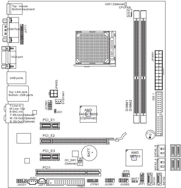
Thank you for choosing the 740GM-P21/ 740GM-P25/ 760GM-P33 series (MS-7623 v1.X) Micro-ATX mainboard. The 740GM-P21/ 740GM-P25/ 760GM-P33 series is design based on AMD® 740G/ 760G & SB710 chipset for optimal system efficiency. Designed to fit the advanced AMD® processor in AM3 package, the 740GM-P21/ 740GM-P25/ 760GM-P33 series deliver a high performance and professional desktop platform solution.
Layout
text_image
Top : mouse Bottom keyboard LED1 (Optional) CPUFAN OM Port JFJ11 VGA port USB ports Top: LAN Jack Bottom: USB ports T:Line-In M:Line- Out B:MIC-Int T: RS-Out (Optional) M: CS-Out (Optional) B: SS-Out (Optional) PCI_E1 JCPM1 JCP1 JFWR2 SYSFAN1 JCI1 AMD 7406/760G (Optional) DIMM1 DIMM2 JPWR1 IDE * PCU PCI_E2 PCI_E3 OC_SW1 (Optional) BATT + PCI1 JCD1 JAD1 JSP1 FDD1 JTPM1 JUSB1 JUSB2 JFJP2 JBAT1 JFP1 SATA1 SATA2SPECIFICATIONS
Processor Support
■ AMD ^® Phenom II/ Athlon II/ Sempron processors in the AM3 package (For the latest information about CPU, please visit http://www.msi.com/index.php?func=cpuform2)
HyperTransport
■ Supports Hyper Transport(HT) 1.0 Technology up to 1000MHz (Optional)
■ Supports Hyper Transport(HT) 3.0 Technology up to 2600MHz (Optional)
Chipset
■ North Bridge: AMD® 740G/ 760G chipset (Optional)
■ South Bridge: AMD® SB710 chipset
Memory Support
■ DDR3 800/1066/1333 (1600 OC) SDRAM (8GB Max)
■ 2 DDR3 DIMMs (240pin / 1.5V)
(For more information on compatible components, please visit http://www.msi.com/index.php?func=testreport)
LAN
■ Supports LAN 10/100/1000 Fast Ethernet by ATHEROS® AR8131M (Optional)
■ Supports LAN 10/100 Fast Ethernet by ATHEROS® AR8132M (Optional)
Audio
■ Chip integrated by VIA® VT1708S
■ Flexible 8-channel audio with jack sensing (Optional)
■ Compliant with Azalia 1.0 Spec
IDE
■ 1 IDE port by AMD® SB710
■ Supports Ultra DMA 33/66/100/133, PIO & Bus Master operation mode
SATA
■ 6 SATA 3Gb/s (SATA1\~6) ports by AMD® SB710
RAID
■ Supports RAID 0/1/0+1/JBOD mode by AMD® SB710
Floppy
■ 1 floppy port
■ Supports 1 FDD with 360KB, 720KB, 1.2MB, 1.44MB and 2.88MB
Connectors
■ Back panel
- 1 PS/2 mouse port
- 1 PS/2 keyboard port
- 1 Serial port
- 1 VGA port
- 4 USB 2.0 Ports
- 1 LAN jack
- 6 flexible audio jacks (Optional)
- 3 flexible audio jacks (Optional)
■ On-Board Connectors
- 2 USB 2.0 connectors
- 1 Serial port connector
- 1 CD-In connector
- 1 Front Panel Audio connector
- 1 SPDIF-Out connector
- 1 Chassis Intrusion connector
- 1 TPM connector (Optional)
- 1 Parallel port connector
- 1 OC switch (Optional)
Slots
■ 1 PCI Express x16 slot
■ 2 PCI Express x1 slots
■ 1 PCI slot, support 3.3V/ 5V PCI bus Interface
Form Factor
■ Micro-ATX (24.4cm X 20.5 cm)
Mounting
■ 6 mounting holes (If you need to purchase accessories and request the part numbers, you could search the product web page and find details on our web address below http://www.msi.com/index.php)
The 740GM-P21 rear panel provides the following connectors:
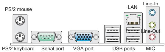
text_image
PS/2 mouse PS/2 keyboard Serial port VGA port USB ports MIC LAN Line-In Line-OutThe 740GM-P25/760GM-P33 rear panel provides the following connectors:
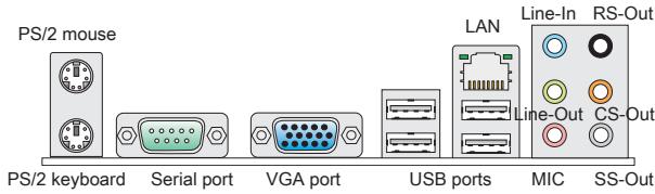
text_image
PS/2 mouse PS/2 keyboard Serial port VGA port USB ports LAN Line-In RS-Out Line-Out CS-Out MIC SS-OutNote: To reach the 8-channel sound effect, the 7th and 8th channels must be output from front panel if you purchase the mainboard with 3 audio jacks
HARDWARE SETUP
This chapter tells you how to install the CPU, memory modules, and expansion cards, as well as how to setup the jumpers on the mainboard. It also provides the instructions on connecting the peripheral devices, such as the mouse, keyboard, etc. While doing the installation, be careful in holding the components and follow the installation procedures.
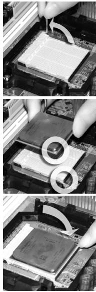
CPU & Cooler Installation for AM3
When you are installing the CPU, make sure the CPU has a cooler attached on the top to prevent overheating. Meanwhile, do not forget to apply some thermal paste on CPU before installing the heat sink/cooler fan for better heat dispersion.
Follow the steps below to install the CPU & cooler correctly. Wrong installation will cause the damage of your CPU & mainboard.
- Pull the lever sideways away from the socket. Make sure to raise the lever up to a 90-degree angle.
- Look for the gold arrow of the CPU. The gold arrow should point as shown in the picture. The CPU can only fit in the correct orientation.
- If the CPU is correctly installed, the pins should be completely embedded into the socket and can not be seen. Please note that any violation of the correct installation procedures may cause permanent damages to your mainboard.
- Press the CPU down firmly into the socket and close the lever. As the CPU is likely to move while the lever is being closed, always close the lever with your fingers pressing tightly on top of the CPU to make sure the CPU is properly and completely embedded into the socket.
- Position the cooling set onto the retention mechanism. Hook one end of the clip to hook first.
- Then press down the other end of the clip to fasten the cooling set on the top of the retention mechanism. Locate the Fix Lever and lift up it.
- Fasten down the lever.
- Attach the CPU Fan cable to the CPU fan connector on the mainboard.
IMPORTANT
* Mainboard photos shown in this section are for demonstration of the cooler installation for Socket AM3 CPU only. The appearance of your mainboard may vary depending on the model you purchase.
* While disconnecting the hook from the fixed bolt, it is necessary to keep an eye on your fingers, because once the hook is disconnected from the fixed bolt, the fixed lever will spring back instantly.
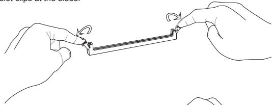
Installing Memory Modules
- The memory module has only one notch on the center and will only fit in the right orientation.
- Insert the memory module vertically into the DIMM slot. Then push it in until the golden finger on the memory module is deeply inserted in the DIMM slot. The plastic clip at each side of the DIMM slot will automatically close when the memory module is properly seated. You can barely see the golden finger if the memory module is properly inserted in the DIMM slot.
- Manually check if the memory module has been locked in place by the DIMM slot clips at the sides.
natural_image
Line drawing of two hands holding a small mechanical component (no text or symbols)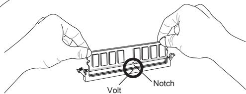
text_image
Volt Notch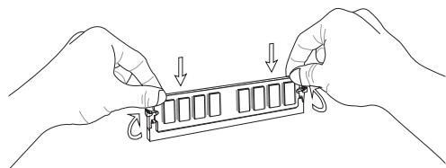
natural_image
Line drawing of two hands holding a RAM module with downward arrows indicating compression or disassembly (no text or symbols)IMPORTANT
* DDR3 memory modules are not interchangeable with DDR2 and the DDR3 standard is not backwards compatible. You should always install DDR3 memory modules in the DDR3 DIMM slots.
* In Dual-Channel mode, make sure that you install memory modules of the same type and density in different channel DIMM slots.
* To enable successful system boot-up, always insert the memory modules into the DIMM1 first.
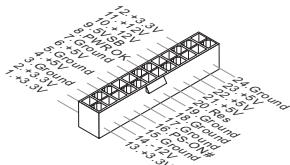
ATX 24-Pin Power Connector: JPWR1
This connector allows you to connect an ATX 24-pin power supply. To connect the ATX 24-pin power supply, make sure the plug of the power supply is inserted in the proper orientation and the pins are aligned. Then push down the power supply firmly into the connector.
text_image
12+3.3V 9+12V 6+24V 2+3.3V Ground Ground Ground Ground 12+3.3V 9+12V 6+24V 2+3.3V 12+3.3V 9+12V 6+24V 2+3.3V Ground Ground Ground Ground 12+3.3V 9+12V 6+24V 2+3.3V 12+3.3V Ground Ground Ground GroundATX 4-Pin Power Connector: JPWR2
This 4-Pin power connector is used to provide power to the CPU.
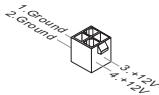
text_image
1. Ground 2. Ground 3 +12V 4 +12VIMPORTANT
* Make sure that all the connectors are connected to proper ATX power supplies to ensure stable operation of the mainboard.
* Power supply of 350 watts (and above) is highly recommended for system stability.
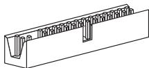
Floppy Disk Drive Connector: FDD1
This connector supports 360KB, 720KB, 1.2MB, 1.44MB or 2.88MB floppy disk drive.
natural_image
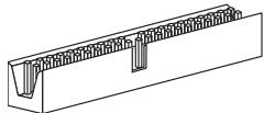
Isometric line drawing of a mechanical component with grooves and a central notch (no text or symbols)IDE Connector: IDE1
This connector supports IDE hard disk drives, optical disk drives and other IDE devices.
natural_image
Technical line drawing of a mechanical component with grooves and a central indentation (no text or symbols)IMPORTANT
If you install two IDE devices on the same cable, you must configure the drives to cable select mode or separately to master / slave mode by setting jumpers. Refer to IDE device documentation supplied by the vendors for jumper setting instructions.
Serial ATA Connector: SATA1 \~ 6
This connector is a high-speed Serial ATA interface port. Each connector can connect to one Serial ATA device.
natural_image
Two technical line drawings of a rectangular electronic component with internal channels (no text or symbols)IMPORTANT
Please do not fold the Serial ATA cable into 90-degree angle. Otherwise, data loss may occur during transmission.
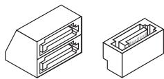
Fan Power Connectors: CPUFAN, SYSFAN1
The fan power connectors support system cooling fan with +12V. When connecting the wire to the connectors, always note that the red wire is the positive and should be connected to the +12V; the black wire is Ground and should be connected to GND. If the mainboard has a System Hardware Monitor chipset onboard, you must use a specially designed fan with speed sensor to take advantage of the CPU fan control.
text_image
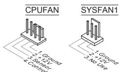
CPUFAN 2 + 12V 3 Sensor 4 Control SYSFAN1 1 Ground 2 + 2V 3 No UseS/PDIF-Out Connector: JSP1
This connector is used to connect S/PDIF (Sony & Philips Digital Interconnect Format) interface for digital audio transmission.
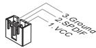
text_image
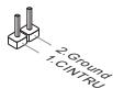
3. Ground 2. SPDIF 1. VCCCD-In Connector: JCD1
This connector is provided for external audio input.
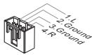
text_image
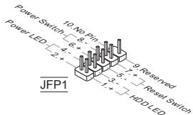
1:L 2:Ground 3:Ground 4:RFront Panel Connectors: JFP1, JFP2
These connectors are for electrical connection to the front panel switches and LEDs. The JFP1 is compliant with Intel® Front Panel I/O Connectivity Design Guide.
text_image
Power Switch 10 No Pin Power LED 9 Reserved Power LED 2 + 7 + Reset Switch JFP1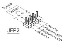
text_image
Speaker Butzer 8 + 6 - 4 + 2 - 7. No Pin 5. Power LED 3. Suspend LED 1. Ground JFP2Serial Port Connector: JCOM1
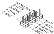
This connector is a 16550A high speed communication port that sends/receives 16 bytes FIFOs. You can attach a serial device.
text_image
10: No Pin 8: CTS 6: DSR 4: DTR 2: SIN 9: RI 7: RTS 5: Ground 3: SOUT 1: DCDFront Panel Audio Connector: JAUD1
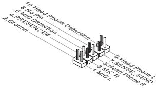
This connector allows you to connect the front panel audio and is compliant with Intel® Front Panel I/O Connectivity Design Guide.
text_image
1. Head Phone Detection 2. No Pin 3. MIC Detection 4. PRESENCE 5. No Pin 6. MIC Detection 7. SENSE SEND 8. MIC 9. Head Phone L 10. MHz Phone N 11. MIC LFront USB Connector: JUSB1, JUSB2
This connector, compliant with Intel ^® I/O Connectivity Design Guide, is ideal for connecting high-speed USB interface peripherals such as USB HDD, digital cameras, MP3 players, printers, modems and the like.
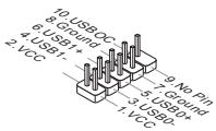
text_image
10. USROC 8. Ground 6. USB1* 4. USB1- 2. VCC 9. No Pin 7. Ground 5. USB0+ 3. USB0- 1. VCCTPM Module connector: JTPM1 (Optional)
This connector connects to a TPM (Trusted Platform Module) module. Please refer to the TPM security platform manual for more details and usages.
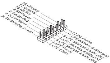
text_image
14 Ground 13. Ground 9. 5V Pin 6. Serial I/O 4. 5V Pin 2. 5V Single Power 13 LPC Frame 9. 5V PC address & data pin 7. LPC clock & data pin 5. LPC address & data pin 1 LPC Clock 13 LPC Caddress & data pinChassis Intrusion Connector: JCI1
This connector connects to the chassis intrusion switch cable. If the chassis is opened, the chassis intrusion mechanism will be activated. The system will record this status and show a warning message on the screen. To clear the warning, you must enter the BIOS utility and clear the record.
Clear CMOS Jumper: JBAT1
There is a CMOS RAM onboard that has a power supply from an external battery to keep the data of system configuration. With the CMOS RAM, the system can automatically boot OS every time it is turned on. If you want to clear the system configuration, set the jumper to clear data.


Keep Data

Clear Data
IMPORTANT
You can clear CMOS by shorting 2-3 pin while the system is off. Then return to 1-2 pin position. Avoid clearing the CMOS while the system is on; it will damage the mainboard.
Parallel Port Header: JLPT1
This connector is used to connect an optional parallel port bracket. The parallel port is a standard printer port that supports Enhanced Parallel Port (EPP) and Extended Capabilities Parallel Port (ECP) mode.
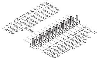
text_image
1.24 NO Pin 2.24 Ground 3.6 Ground 4.70 Ground 6 PINL# - SN-## 2.4FZB 1.25 SLOT 2.3 PNDY 3.9 PNDY 5.1 PRN15 6 PINL#- 7 PIND 8 PIND 9 RSTB 10 PNDY 11 RSTB 12 PNDY 13 PNDY 14 PNDY 15 RSTB 16 PNDY 17 RSTB 18 PNDY 19 RSTB 20 PNDY 21 RSTB 22 PNDY 23 RSTB 24 PNDY 25 RSTBAPS LED Status Indicator: LED1 (Optional)
These APS (Active Phase Switching) LED indicates the current CPU power phase mode. Follow the instructions below to read.
LED1

| ON | The LED will light when CPU is in 3 phase power mode. |
| OFF | The LED will go off when CPU is in 1 phase power mode. |
Overclock FSB Switch: OC\_SW1 (Optional)
You can overclock the FSB to increase the processor frequency by changing the switch. Follow the instructions below to set the FSB.

Default

Increase 10% speed of FSB

Increase 15% speed of FSB

Increase 20% speed of FSB
IMPORTANT
* Make sure that you power off the system before setting the switch.
* When overclocking cause system instability or crash during boot, please set the switch to default setting.
PCI Express Slot
The PCI Express slot supports the PCI Express interface expansion card.
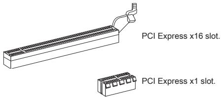
PCI Express x16 slot.
PCI Express x1 slot.
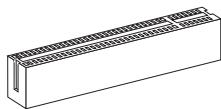
PCI Slot
The PCI slot supports LAN card, SCSI card, USB card, and other add-on cards that comply with PCI specifications.
natural_image
Isometric line drawing of a rectangular structural component with evenly spaced notches (no text or symbols)IMPORTANT
Make sure that you unplug the power supply first. Meanwhile, read the documentation for the expansion card to configure any necessary hardware or software settings for the expansion card, such as jumpers, switches or BIOS configuration.
PCI Interrupt Request Routing
When adding or removing expansion cards, make the IRQ, acronym of interrupt request line and pronounced I-R-Q, are hardware lines over which devices can send interrupt signals to the microprocessor. The PCI IRQ pins are typically connected to the PCI bus pins as follows:
| Slot\Order | 1 | 2 | 3 | 4 |
| PCI 1 | INT A# | INT B# | INT C# | INT D# |
BIOS SETUP
Power on the computer and the system will start POST (Power On Self Test) process. When the message below appears on the screen, press key to enter Setup.
Press DEL to enter SETUP
If the message disappears before you respond and you still wish to enter Setup, restart the system by turning it OFF and On or pressing the RESET button. You may also restart the system by simultaneously pressing
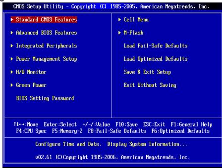
Main Page
text_image
CMOS Setup UTILITY - Copyright (C) 1985-2006, American Megatrends, Inc. ►Standard CMOS Features ►Advanced BIOS Features ►Integrated Peripherals ►Power Management Setup ►H/W Monitor ►Green Power BIOS Setting Password ►Cell Menu ►M-Flash Load Fail-Safe Defaults Load Optimized Defaults Save & Exit Setup Exit Without Saving F1:→:Move Enter:Select +/-/Value F10:Save ESC:Exit F1:General Help F4:CPU Spec F5:Memory-Z F8:Fail-Safe Defaults F6:Optimized Defaults Configure Time and Date. Display System Information... w02.61 (C)Copyright 1985-2006, American Megatrends, Inc.Standard CMOS Features
Use this menu for basic system configurations, such as time, date etc.
Advanced BIOS Features
Use this menu to setup the items of special enhanced features.
Integrated Peripherals
Use this menu to specify your settings for integrated peripherals.
Power Management Setup
Use this menu to specify your settings for power management.
H/W Monitor
This entry shows the status of your CPU, fan, warning for overall system status.
Green Power (Optional)
Use this menu to specify the power phase.
BIOS Setting Password
Use this menu to set BIOS setting Password.
Cell Menu
Use this menu to specify your settings for frequency/voltage control.
M-Flash
Use this menu to read/ flash the BIOS from storage drive (FAT/ FAT32 format only).
Load Fail-Safe Defaults
Use this menu to load the BIOS default values that are factory settings for system operations.
Load Optimized Defaults
Use this menu to load factory default settings into the BIOS for stable system performance operations.
Save & Exit Setup
Save changes to CMOS and exit setup.
Exit Without Saving
Abandon all changes and exit setup.
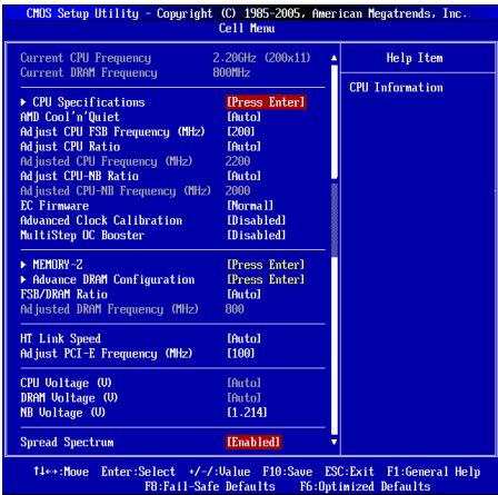
Cell Menu
text_image
CMOS Setup Utility - Copyright (C) 1985-2005, American Megatrends, Inc. Cell Menu Current CPU Frequency 2.20GHz (200x11) Current DRAM Frequency 800MHz ▶ CPU Specifications [Press Enter] AMD Cool'n'Quiet [Intol] Adjust CPU FSB Frequency (MHz) [200] Adjust CPU Ratio [Intol] Adjusted CPU Frequency (MHz) 2200 Adjust CPU-NB Ratio [Intol] Adjusted CPU-NB Frequency (MHz) 2000 DC Firmware [Normal] Advanced Clock Calibration [Disabled] MultiStep DC Booster [Disabled] ▶ MEMORY 2 [Press Enter] ▶ Advance DRAM Configuration [Press Enter] FSB/DRAM Ratio [Intol] Adjusted DRAM Frequency (MHz) 800 HT Link Speed [Intol] Adjust PCI-E Frequency (MHz) [100] CPU Voltage (U) [Intol] DRAM Voltage (U) [Intol] ND Voltage (U) [.214] Spread Spectrum [Enabled] T4→:Move Enter:Select +/-Value P10:Save ESC:Exit P1:General Help FB:Fail-Safe Defaults FB:Optimized Defaults Help Item CPU InformationCurrent CPU/DRAM Frequency
It shows the current frequency of CPU/Memory. Read-only.
CPU Specifications
Press
AMD Cool'n'Quiet
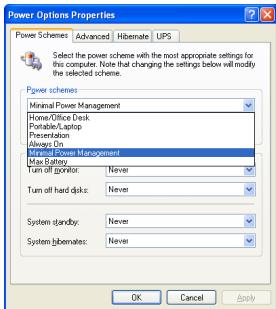
The Cool'n'Quiet technology can effectively and dynamically lower CPU speed and power consumption.
IMPORTANT
To ensure that Cool'n'Quiet function is activated and will be working properly, it is required to double confirm that:
* Run BIOS Setup, and select Cell Menu. Under Cell Menu, find AMD Cool'n'Quiet, and set this item to "Enabled".
* Enter Windows, and select [Start]->[Settings]->[Control Panel]->[Power Options]. Enter Power Options Properties tag, and select Minimal Power Management under Power schemes.
text_image
Power Options Properties Power Schemes Advanced Hibernate UPS Select the power scheme with the most appropriate settings for this computer. Note that changing the settings below will modify the selected scheme. Power schemes Minimal Power Management Home/Office Desk Portable/Laptop Presentation Always On Minimal Power Management Max Battery Turn off Monitor: Never Turn off hard disks: Never System standby: Never System libemates: Never OK Cancel ApplyAdjust CPU FSB Frequency (MHz)
This item allows you to adjust the CPU FSB frequency.
Adjust CPU Ratio
This item is used to adjust CPU clock multiplier (ratio). It is available only when the processor supports this function.
Adjusted CPU Frequency (MHz)
It shows the adjusted CPU frequency. Read-only.
Adjust CPU-NB Ratio
This item is used to adjust CPU-NB ratio.
Adjusted CPU-NB Frequency (MHz)
It shows the adjusted CPU-NB frequency. Read-only.
EC Firmware
This item allows you to select the EC Firmware for Advanced Clock Calibration. For unlocking the additional cores, you could set it [Special] and then set Advanced Clock Calibration [Auto] in order to be able to activate the processor cores.
Advanced Clock Calibration
This item is for overclock. Setting to [Enabled] allows you to set the CPU Ratio higher. It is available only when the processor supports this function.
MultiStep OC Booster
This item is used to avoid the BIOS might crash with overclocking. Setting to [Disabled] disable this item, apply OC settings during POST. [Mode 1] Slight OC during POST and then apply full OC when loading the OS. [Mode 2] Load the OS then apply the OC settings.
MEMORY-Z
Press
Advance DRAM Configuration
Press
DRAM Timing Mode
Selects whether DRAM timing is controlled by the SPD (Serial Presence Detect) EEPROM on the DRAM module. Setting to [Auto By SPD] enables DRAM timings and the following related items to be determined by BIOS based on the configurations on the SPD. Selecting [Manual] allows users to configure the DRAM timings and the following related items manually.
CAS Latency (CL)
When the DRAM Timing Mode sets to [Manual], the field is adjustable. This controls the CAS latency, which determines the timing delay (in clock cycles) before SDRAM starts a read command after receiving it.
TRCD
When the DRAM Timing Mode sets to [Manual], the field is adjustable. When DRAM is refreshed, both rows and columns are addressed separately. This setup item allows you to determine the timing of the transition from RAS (row address strobe) to CAS (column address strobe). The less the clock cycles, the
faster the DRAM performance.
TRP
When the DRAM Timing Mode sets to [Manual], the field is adjustable. This setting controls the number of cycles for Row Address Strobe (RAS) to be allowed to precharge. If insufficient time is allowed for the RAS to accumulate its charge before DRAM refresh may be incomplete and DRAM may fail to retain data. This item applies only when synchronous DRAM is installed in the system.
TRAS
When the DRAM Timing Mode sets to [Manual], the field is adjustable. This setting determines the time RAS takes to read from and write to a memory cell.
TRTP
When the DRAM Timing Mode sets to [Manual], the field is adjustable. This setting controls the time interval between a read and a precharge command.
TRC
When the DRAM Timing Mode sets to [Manual], the field is adjustable. The row cycle time determines the minimum number of clock cycles a memory row takes to complete a full cycle, from row activation up to the precharging of the active row.
TWR
When the DRAM Timing Mode sets to [Manual], the field is adjustable. It specifies the amount of delay (in clock cycles) that must elapse after the completion of a valid write operation, before an active bank can be precharged. This delay is required to guarantee that data in the write buffers can be written to the memory cells before precharge occurs.
TRRD
When the DRAM Timing Mode sets to [Manual], the field is adjustable. Specifies the active-to-active delay of different banks.
TWTR
When the DRAM Timing Mode sets to [Manual], the field is adjustable. This item controls the Write Data In to Read Command Delay memory timing. This constitutes the minimum number of clock cycles that must occur between the last valid write operation and the next read command to the same internal bank of the DDR device.
1T/2T Memory Timing
When the DRAM Timing Mode sets to [Manual], the field is adjustable. This field controls the SDRAM command rate. Selecting [1T] makes SDRAM signal controller to run at 1T (T=clock cycles) rate. Selecting [2T] makes SDRAM signal controller run at 2T rate.
SoftWare Memory Hole
When the DRAM Timing Mode sets to [Manual], the field is adjustable. This field allows you to enable or disable SoftWare Memory Hole.
FSB/DRAM Ratio
This item allows you to set the FSB/DRAM ratio.
Adjusted DRAM Frequency (MHz)
It shows the adjusted DDR memory frequency. Read-only.
HT Link Speed
This item allows you to set the Hyper-Transport Link speed. Setting to [Auto], the system will detect the HT link speed automatically.
Adjust PCI-E Frequency (MHz)
This item allows you to set the PCI-E frequency (in MHz).
CPU Voltage (V)
This item will allow you to adjust the CPU voltage.
DRAM Voltage (V)
This item will allow you to adjust the Memory voltage.
NB Voltage (V)
This item will allow you to adjust the North Bridge voltage.
Spread Spectrum
When the motherboard's clock generator pulses, the extreme values (spikes) of the pulses create EMI (Electromagnetic Interference). The Spread Spectrum function reduces the EMI generated by modulating the pulses so that the spikes of the pulses are reduced to flatter curves. If you do not have any EMI problem, leave the setting at Disabled for optimal system stability and performance. But if you are plagued by EMI, set to Enabled for EMI reduction. Remember to disable Spread Spectrum if you are overclocking because even a slight jitter can introduce a temporary boost in clock speed which may just cause your overclocked processor to lock up.
IMPORTANT
* If you do not have any EMI problem, leave the setting at [Disabled] for optimal system stability and performance. But if you are plagued by EMI, select the value of Spread Spectrum for EMI reduction.
* The greater the Spread Spectrum value is, the greater the EMI is reduced, and the system will become less stable. For the most suitable Spread Spectrum value, please consult your local EMI regulation.
* Remember to disable Spread Spectrum if you are overclocking because even a slight jitter can introduce a temporary boost in clock speed which may just cause your overclocked processor to lock up.
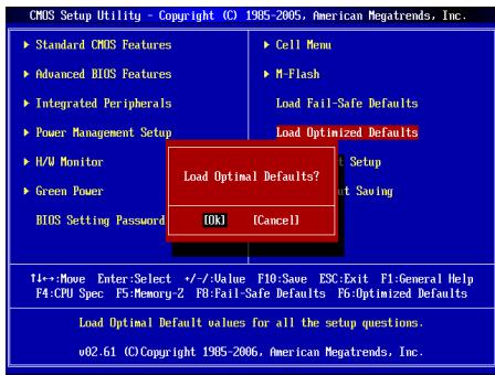
Load Optimized Defaults
You can load the default values provided by the mainboard manufacturer for the stable performance.
text_image
CMOS Setup Utility - Copyright (C) 1985-2006, American Megatrends, Inc. ► Standard CMOS Features ► Advanced BIOS Features ► Integrated Peripherals ► Power Management Setup ► H/W Monitor ► Green Power BIOS Setting Password ► Cell Menu ► M-Flash Load Fail-Safe Defaults Load Optimized Defaults Load Optimal Defaults? [OK] [Cancel] 1+->:Move Enter:Select +/-Value F10:Save ESC:Exit F1:General Help F4:CPU Spec F5:Memory-2 F8:Fail-Safe Defaults F6:Optimized Defaults Load Optimal Default values for all the setup questions. v02.61 (C)Copyright 1985-2006, American Megatrends, Inc.한국어
시작하기
natural_image
Isometric line drawing of a mechanical component with spring-like grooves and a central V-shaped groove (no text or symbols)IDE 커넥터: IDE1
natural_image
Isometric line drawing of a structural support frame with embedded columns (no text or symbols)중요 사항
natural_image
Two technical line drawings of a rectangular electronic component with internal channels (no text or symbols)중요 사항
text_image
1. L 2. Ground 3. Ground 4. Rtext_image
Power Switch 8 Power LED 2 JFP1 10 No Pin 9 Reserved Reset Switch 4 5 3 1, + HDD LED
text_image
Speaker Buzzer 8 + 6 - 4 + 12 - 7: No Pin 5: Power LED 3: Suspend LED 1: Ground JFP2시리얼 포트 커넥터: JCOM1
text_image
10: No Pin 8: CFS 6: DSR 4: DTR 2: SIN 9: R1 7: RTS 5: Ground 3: SOUT 1: DCD전면 패널 오디오 커넥터:JAUD1
text_image
1.0 Head Phone Detection 4. No Pin 6. MIC Detection 2. Ground 9. Head Phone L 7. SENSE SEND 5. Head Phone R 1. MIC Ltext_image
10: USBOC 8: Ground 6: USB1+ 4: USB1- 2: VCC 9: No Pin 5: USB0+ 3: USB0- 1: VCCnatural_image
Line drawing of a rectangular mechanical component with a protruding bracket (no text or symbols)PCI Express x16 슬롯.

PCI Express x1 슬롯.
PCI 슬롯
natural_image
Isometric line drawing of a rectangular structural component with evenly spaced notches (no text or symbols)중요 사항
| 순서슬롯 | 1 | 2 | 3 | 4 |
| PCI 1 | INT A# | INT B# | INT C# | INT D# |
Press DEL to enter SETUP
text_image
CMOS Setup Utility - Copyright (C) 1985-2005, American Megatrends, Inc. Cell Menu Current CPU Frequency 2.26GHz (200x11) Current DRAM Frequency 800MHz ► CPU Specifications [Press Enter] AMD Cool'n'Quiet [Intol] Adjust CPU FSB Frequency (MHz) [200] Adjust CPU Ratio [Intol] Adjusted CPU Frequency (MHz) 2200 Adjust CPU-MB Ratio [Intol] Adjusted CPU-MB Frequency (MHz) 2000 EC Firmware [Normal] Advanced Clock Calibration [Disabled] MultiStep DC Booster [Disabled] ► MEMORY-2 [Press Enter] ► Advance DRAM Configuration [Press Enter] FSB/DRAM Ratio [Intol] Adjusted DRAM Frequency (MHz) 800 HT Link Speed [Intol] Adjust PCI-E Frequency (MHz) [100] CPU Voltage (U) [Intol] DRAM Voltage (U) [Intol] MD Voltage (U) [.214] Spread Spectrum [Enabled] T←→:Move Enter:Select +/-Value F10:Save ESC:Exit F1:General Help FB:Fail-Safe Defaults FB:Optimized Defaults Help Item CPU InformationCurrent CPU/DRAM Frequency (현재 CPU / DRAM 주파수)
text_image
Power Options Properties Power Schemes Advanced Hibernate UPS Select the power scheme with the most appropriate settings for this computer. Note that changing the settings below will modify the selected scheme. Power schemes: Minimal Power Management Home/Office Desk Portable/laptop Presentation Always On Minimum Power Management Max Battery Turn off sponsor: Never Turn off hard disks: Never System standby: Never System jibemates: Never OK Cancel ApplyAdjusted CPU Frequency (조정된 CPU 주파수) (MHz)
Adjusted CPU-NB Frequency (조정된 CPU-NB 주파수) (MHz)
EC Firmware (EC 펌웨어)
Adjusted DRAM Frequency (조정된 DRAM 주파수) (MHz)
CPU Voltage (V) (CPU 전압 (V))
DRAM Voltage (V) (DRAM 전압 (V))
NB Voltage (V) (NB 전압 (V))
natural_image
Isometric line drawing of a mechanical component with spring-like grooves and a central V-shaped groove (no text or symbols)natural_image
Technical line drawing of a mechanical component with grooves and a central indentation (no text or symbols)IMPORTANT
natural_image
Two technical line drawings of a rectangular electronic component with internal channels (no text or symbols)IMPORTANT
text_image
PowerSwitch 10 No Pin PowerLED 2+ - 9 Reserved 7+ Reset Switch 5- HDD LED 3+ -9 reserved JFP1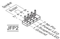
text_image
Speaker Butzer 8 + 13 4 + 7: No Pin 5 Power LED 3 Suspend LED 1 Ground JFP2text_image
10: No Pm 8: CTS 6: DSR 4: DTR 2: SIN 9: R1 7: RTS 5: Ground 3: SOUT 1: DCDnatural_image
Isometric line drawing of a rectangular structural component with evenly spaced notches (no text or symbols)IMPORTANT
Press DEL to enter SETUP
Advanced BIOS Features
Integrated Peripherals
BIOS Setting Password
text_image
CMOS Setup Utility - Copyright (C) 1985-2005, American Megatrends, Inc. Cell Menu Current CPU Frequency 2.20GHz (200x11) Current DRAM Frequency 800MHz ► CPU Specifications [Press Enter] AMD Cool'n'Quiet [Intol] Adjust CPU FSB Frequency (MHz) [200] Adjust CPU Ratio [Intol] Adjusted CPU Frequency (MHz) 2200 Adjust CPU-MB Ratio [Intol] Adjusted CPU-MB Frequency (MHz) 2000 EC Firmware [Normal] Advanced Clock Calibration [Disabled] MultiStep DC Booster [Disabled] ► MEMORY-2 [Press Enter] ► Advance DRAM Configuration [Press Enter] FSB/DRAM Ratio [Intol] Adjusted DRAM Frequency (MHz) 800 HT Link Speed [Intol] Adjust PCI-E Frequency (MHz) [100] CPU Voltage (U) [Intol] DRAM Voltage (U) [Intol] MD Voltage (U) [.214] Spread Spectrum [Enabled] T←→:Move Enter:Select +/-Value F10:Save ESC:Exit F1:General Help FB:Fail-Safe Defaults FB:Optimized Defaults Help Item CPU InformationCurrent CPU/DRAM Frequency
text_image
Power Options Properties Power Schemes Advanced Hibernate UPS Select the power scheme with the most appropriate settings for this computer. Note that changing the settings below will modify the selected scheme. Power schemes Minimal Power Management Home/Office Desk Portable/Laptop Presentation Always On Minimal Power Management Max Battery Turn off sponsor: Never Turn off hard disks: Never System standby: Never System libemates: Never OK Cancel ApplyAdjust CPU FSB Frequency (MHz)
Adjusted CPU Frequency (MHz)
Adjusted CPU-NB Frequency (MHz)
Advanced Clock Calibration
Adjusted DRAM Frequency (MHz)
Adjust PCI-E Frequency (MHz)
■ On-Board Anschlüsse
natural_image
Close-up of a microprocessor on a circuit board with a tool inserted, no visible text or symbols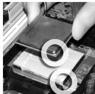
natural_image
Close-up of hands installing a CPU socket into a motherboard, with two circular insets highlighting the components (no text or symbols visible)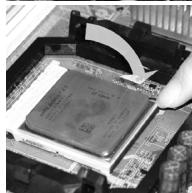
natural_image
Close-up of a computer processor on a motherboard with a hand inserting a component (no visible text or symbols)WICHTIG
text_image
Diagram illustrating three-step electrical circuit steps for a battery, showing voltage and kerbe components with directional arrows.WICHTIG
natural_image
Isometric line drawing of a mechanical component with grooves and a central notch (no text or symbols)IDE Anschluss: IDE1
natural_image
Technical line drawing of a mechanical component with grooves and a central indentation (no text or symbols)WICHTIG
natural_image
Two technical line drawings of a rectangular electronic component with internal channels (no text or symbols)WICHTIG
text_image
1. L 2. Ground 3. Ground 4. RFrontpanel Anschlüsse: JFP1, JFP2
text_image
Power Switch 10, No Pin 6 + Power LED 4- 2 + JFP1 9. Reserved 5. + - Reset Switch 3 - HDD LED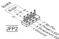
text_image
Speaker Buzzer 8 + 6 - 4 + 2 - 7: No Pin 5: Power LED 3: Suspend LED 1: Ground JFP2natural_image
Line drawing of a rectangular mechanical component with a protruding bracket (no text or symbols)natural_image
Isometric line drawing of a rectangular structural component with evenly spaced notches (no text or symbols)WICHTIG
Press DEL to enter SETUP
Advanced BIOS Features
Integrated Peripherals
BIOS Setting Password
text_image
CMOS Setup Utility - Copyright (C) 1985-2005, American Megatrends, Inc. Cell Menu Current CPU Frequency 2.20GHz (200x11) Current DRAM Frequency 800MHz ▶ CPU Specifications [Press Enter] AMD Cool'n'Quiet [Intol] Adjust CPU FSB Frequency (MHz) [200] Adjust CPU Ratio [Intol] Adjusted CPU Frequency (MHz) 2200 Adjust CPU-NB Ratio [Intol] Adjusted CPU-NB Frequency (MHz) 2000 DC Firmware [Normal] Advanced Clock Calibration [Disabled] MultiStep DC Booster [Disabled] ▶ MEMORY 2 [Press Enter] ▶ Advance DRAM Configuration [Press Enter] FSB/DRAM Ratio [Intol] Adjusted DRAM Frequency (MHz) 800 HT Link Speed [Intol] Adjust PCI-E Frequency (MHz) [100] CPU Voltage (U) [Intol] DRAM Voltage (U) [Intol] ND Voltage (U) [.214] Spread Spectrum [Enabled] T4→:Move Enter:Select +/-Value P10:Save ESC:Exit P1:General Help FB:Fail-Safe Defaults FB:Optimized Defaults Help Item CPU InformationCurrent CPU/DRAM Frequency
text_image
Power Options Properties Power Schemes Advanced Hibernate UPS Select the power scheme with the most appropriate settings for this computer. Note that changing the settings below will modify the selected scheme. Power schemes Minimal Power Management Home/Office Desk Portable/Laptop Presentation Always On Binary Systems Management Max Battery Turn off monitor: Never Turn off hard disks: Never System standby: Never System libemates: Never OK Cancel ApplyAdjust CPU FSB Frequency (MHz)
Adjusted CPU Frequency (MHz)
Adjusted CPU-NB Frequency (MHz)
Advanced Clock Calibration
When the DRAM Timing Mode sets to [Manual], the field is adjustable. It specifies the amount of delay (in clock cycles) that must elapse after the completion of a valid write operation, before an active bank can be precharged. This delay is required to guarantee that data in the write buffers can be written to the memory cells before precharge occurs.
TRRD
Adjusted DRAM Frequency (MHz)
Adjust PCI-E Frequency (MHz)
natural_image
Close-up of a hand holding a small electronic component over a CPU socket (no visible text or symbols)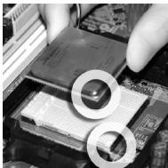
natural_image
Close-up of hands holding a computer motherboard with two circular insets highlighting internal components (no visible text or symbols)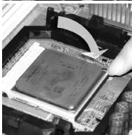
natural_image
Close-up of a CPU socket being inserted into a motherboard, with a hand adjusting the socket (no visible text or symbols)ВНИМАНИЕ
natural_image
Line drawing of two hands holding a mechanical component (no text or symbols)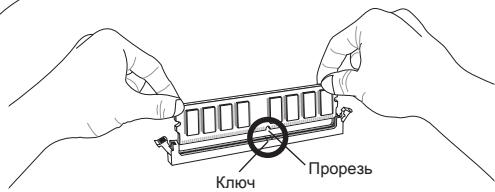
text_image
Ключ Прорезь
natural_image
Line drawing of two hands holding a RAM module with downward arrows indicating compression or disassembly (no text or symbols)КЛЮЧ ВНИМАНИЕ
text_image
1. Ground 2. Ground 3. ×12V 4. ×12VВНИМАНИЕ
natural_image
Isometric line drawing of a mechanical component with spring-like grooves and a central notch (no text or symbols)Разъем IDE: IDE1
natural_image
Technical line drawing of a mechanical component with grooves and supports (no text or symbols)ВНИМАНИЕ
natural_image
Two technical line drawings of a rectangular electronic component with internal channels (no text or symbols)ВНИМАНИЕ
text_image
Power Switch 10 No Pin Power LED 9 Reserved Power LED 2 + 7 + Reset Switch JFP1 1. + HDD LED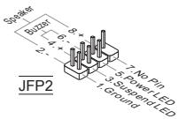
text_image
Speaker Butzer 8 6 4 2 7: No Pin 5: Power LED 3: Suspend LED 1: Ground JFP2text_image
10: No Pin 8: CTS 6: DSR 4: DTR 2: SIN 9: R1 7: RTS 5: Ground 3: SOUT 1: DCDtext_image
10: USBOC 8 Ground 6 USB1+ 4 USB1- 2 VCC 9: No Pin 5 USB0+ 3: USB0- 1: VCCtext_image
12A NO P+N 12B Ground 12B Ground 14 B Ground 14 C Ground 8 L Print S 6 PRND S 4 PRND S 2 A PCD 12S SLOT 12B BUSY 13 ACOM 13 PRNDS 9 PRND S 13 PRNDS 13 PRND S 13 PRND S 1 RS I/O 12A 0.0000000000000000000000000000000000000000000000000000000000000000000000000000000000000000natural_image
Line drawing of a rectangular mechanical component with a protruding bracket (no text or symbols)PCI Express x16 слот.

PCI Express x1 слот.
Слот PCI
natural_image
Isometric line drawing of a rectangular structural component with evenly spaced notches (no text or symbols)ВНИМАНИЕ
text_image
CMOS Setup Utility - Copyright (C) 1985-2005, American Megatrends, Inc. Cell Menu Current CPU Frequency 2.20GHz (200x11) Current DRAM Frequency 800MHz ▶ CPU Specifications [Press Enter] AMD Cool'n'Quiet [Intol] Adjust CPU FSB Frequency (MHz) [200] Adjust CPU Ratio [Intol] Adjusted CPU Frequency (MHz) 2200 Adjust CPU-NB Ratio [Intol] Adjusted CPU-NB Frequency (MHz) 2000 DC Firmware [Normal] Advanced Clock Calibration [Disabled] MultiStep DC Booster [Disabled] ▶ MEMORY 2 [Press Enter] ▶ Advance DRAM Configuration [Press Enter] FSB/DRAM Ratio [Intol] Adjusted DRAM Frequency (MHz) 800 HT Link Speed [Intol] Adjust PCI-E Frequency (MHz) [100] CPU Voltage (U) [Intol] DRAM Voltage (U) [Intol] ND Voltage (U) [.214] Spread Spectrum [Enabled] T4→:Move Enter:Select +/-Value P10:Save ESC:Exit P1:General Help FB:Fail-Safe Defaults FB:Optimized Defaults Help Item CPU InformationCurrent CPU/DRAM Frequency
text_image
Power Options Properties Power Schemes Advanced Hibernate UPS Select the power scheme with the most appropriate settings for this computer. Note that changing the settings below will modify the selected scheme. Power schemes Minimal Power Management Home/Office Desk Portable Laptop Presentation Always On Minimal Power Management Max Battery Turn off Monitor: Never Turn off hard disks: Never System standby: Never System libemates: Never OK Cancel ApplyAdjust CPU FSB Frequency (MΓμ)
Adjusted CPU Frequency (MΓμ)
Adjusted CPU-NB Frequency (MΓμ)
Advanced Clock Calibration
Adjusted DRAM Frequency (MΓμ)
Adjust PCI-E Frequency (MΓμ)
natural_image
Isometric line drawing of a mechanical component with spring-like grooves and a central V-shaped groove (no text or symbols)IDE 接口: IDE1
natural_image
Technical line drawing of a mechanical component with threaded fasteners and a central bracket (no text or symbols)注意
natural_image
Two technical line drawings of a rectangular electronic component with internal channels (no text or symbols)注意
text_image
Power Switch 10 No Pin Power LED 2 + Power LED 4 + Power LED 5 + 7 + Reset Switch JFP1 9 Reserved 1 + HDD LED
text_image
Speaker Buzzer 8 + 6 - 4 + 2 - 7. No Pin 5. Power LED 3. Suspend LED 1. Ground JFP2串行端口接口: JCOM1
text_image
10: No Pin 8: CTS 6: DSR 4: DTR 2: SIN 9: RI 7: RTS 5: Ground 3: SOUT 1: DCD前置音频接口: JAUD1
text_image
10: USBOC 8 Ground 6: USB1+ 4: USB1- 2: VCC 9: No Pin 7: Ground 5: USBD+ 3: USBD+ 1: VCCAPS LED 状态指示: LED1 (选配)
natural_image
Isometric line drawing of a rectangular structural component with evenly spaced notches (no text or symbols)注意
Press DEL to enter SETUP
Integrated Peripherals (整合周边)
使用此菜单可对周边设备进行特别的设定。
text_image
CMOS Setup Utility - Copyright (C) 1985-2005, American Megatrends, Inc. Cell Menu Current CPU Frequency 2.20GHz (200x11) Current DRAM Frequency 800MHz ▶ CPU Specifications [Press Enter] AMD Cool'n'Quiet [Intol] Adjust CPU FSB Frequency (MHz) [200] Adjust CPU Ratio [Intol] Adjusted CPU Frequency (MHz) 2200 Adjust CPU-NB Ratio [Intol] Adjusted CPU-NB Frequency (MHz) 2000 DC Firmware [Normal] Advanced Clock Calibration [Disabled] MultiStep DC Booster [Disabled] ▶ MEMORY 2 [Press Enter] ▶ Advance DRAM Configuration [Press Enter] FSB/DRAM Ratio [Intol] Adjusted DRAM Frequency (MHz) 800 HT Link Speed [Intol] Adjust PCI-E Frequency (MHz) [100] CPU Voltage (U) [Intol] DRAM Voltage (U) [Intol] ND Voltage (U) [.214] Spread Spectrum [Enabled] T4→:Move Enter:Select +/-Value P10:Save ESC:Exit P1:General Help FB:Fail-Safe Defaults FB:Optimized Defaults Help Item CPU InformationCurrent CPU/DRAM Frequency (当前 CPU / 内存频率)
text_image
Power Options Properties Power Schemes Advanced Hibernate UPS Select the power scheme with the most appropriate settings for this computer. Note that changing the settings below will modify the selected scheme. Power schemes Minimal Power Management Home/Office Desk Portable/Laptop Presentation Always On Minimal Power Management Max Battery Turn off Monitor: Never Turn off hard disks: Never System standby: Never System libemates: Never OK Cancel ApplyAdjust CPU FSB Frequency (MHz) (调整 CPU FSB 频率,单位 MHz)
Adjust CPU Ratio (调整 CPU 倍频)
Advanced Clock Calibration (高级时钟校准)
text_image
12+3.3V 9+12V 6+10V 5+9V 4+8V 3+7V 2+6V 1+5V 0+4V Ground Ground Ground Ground Ground Ground Ground Ground Ground Ground Ground Ground Ground Ground Ground Ground Ground Ground Ground Ground Ground Ground Ground Ground Ground Ground Ground Ground Ground Ground Ground Ground Ground Ground Ground Ground Ground Ground Ground Ground Ground Ground Ground Ground Ground Ground Ground Ground Ground Ground 24 Ground 23+3.5V 20+3.5V 18+3.5V 16+3.5V 14+3.5V 12+3.5Vnatural_image
Isometric line drawing of a mechanical component with spring-like grooves and a central V-shaped groove (no text or symbols)IDE 電源連接器:IDE1
natural_image
Technical line drawing of a mechanical component with threaded fasteners (no text or symbols)注意事項
natural_image
Two technical line drawings of a rectangular electronic component with internal channels (no text or symbols)注意事項
text_image
Power Switch 8 Power LED 2 JFP1 10 No Pin 9 Reserved Reset Switch 4 5 3 1, 1 HDD LED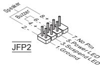
text_image
Speaker Buzzer 8 + 6 - 4 + 12 - 7: No Pin 5: Power LED 3: Suspend LED 1: Ground JFP2序列埠連接器:JCOM1
text_image
10: No Pin 8: CTS 6: DSR 4: DTR 2: SIN 9: RI 7: RTS 5: Ground 3: SOUT 1: DCD面板音效連接器:JAUD1
text_image
10: USBOC 8 Ground 6 USB1+ 4 USB1- 2 VCC 9: No Pin 7 Ground 5: USBO+ 3: USB0- 1 VCCTPM 連接器:JTPM1 (選配)
natural_image
Isometric line drawing of a rectangular structural component with evenly spaced notches (no text or symbols)注意事項
Press DEL to enter SETUP
(按 DEL 鍵進入設定)
Integrated Peripherals (整合型週邊)
使用本選單設定整合型週邊裝置。
text_image
CMOS Setup Utility - Copyright (C) 1985-2005, American Megatrends, Inc. Cell Menu Current CPU Frequency 2.20GHz (200x11) Current DRAM Frequency 800MHz ► CPU Specifications [Press Enter] AMD Cool'n'Quiet [Intol] Adjust CPU FSB Frequency (MHz) [200] Adjust CPU Ratio [Intol] Adjusted CPU Frequency (MHz) 2200 Adjust CPU-MB Ratio [Intol] Adjusted CPU-MB Frequency (MHz) 2000 EC Firmware [Normal] Advanced Clock Calibration [Disabled] MultiStep DC Booster [Disabled] ► MEMORY-2 [Press Enter] ► Advance DRAM Configuration [Press Enter] FSB/DRAM Ratio [Intol] Adjusted DRAM Frequency (MHz) 800 HT Link Speed [Intol] Adjust PCI-E Frequency (MHz) [100] CPU Voltage (U) [Intol] DRAM Voltage (U) [Intol] MD Voltage (U) [.214] Spread Spectrum [Enabled] T←→:Move Enter:Select +/-Value F10:Save ESC:Exit F1:General Help FB:Fail-Safe Defaults FB:Optimized Defaults Help Item CPU InformationCPU Specifications (CPU 規格)
text_image
Power Options Properties Power Schemes Advanced Hibernate UPS Select the power scheme with the most appropriate settings for this computer. Note that changing the settings below will modify the selected scheme. Power schemes Minimal Power Management Home/Office Desk Portable/Laptop Presentation Alives-On Max Battery Turn off monitor: Never Turn off hard disks: Never System standby: Never System libemates: Never OK Cancel ApplyAdjust CPU FSB Frequency (MHz) (調整 CPU FSB 頻率)
本項可手動調整 CPU FSB 頻率。
Adjust CPU Ratio (調整 CPU 倍頻比率)
本項調整 CPU 倍頻比率。
Adjusted CPU Frequency (MHz) (調整後 CPU 頻率)
Advanced Clock Calibration (進階時脈校正)
CPU Voltage (V) (CPU電壓)
本項可調整CPU電壓。
DRAM Voltage (V) (記憶體電壓)
本項可調整記憶體電壓。
NB Voltage (V)
本項可調整北橋晶片電壓。
Spread Spectrum (頻譜擴散組態)
natural_image
Line drawing of two hands holding a mechanical component (no text or symbols)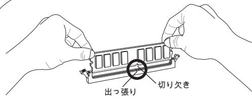
natural_image
Line drawing of two hands installing a memory module with downward arrows indicating compression (no text or symbols)注意
natural_image
Isometric line drawing of a mechanical component with spring-like grooves and a central V-shaped groove (no text or symbols)IDEコネクター: IDE1
natural_image
Isometric line drawing of a structural component with vertical supports and a central notch (no text or symbols)注意
natural_image
Two technical line drawings of a rectangular electronic component with internal channels (no text or symbols)注意
text_image
1. L 2. Ground 3. Ground 4. Rtext_image
Power Switch 10 No Pin Power LED 9 Reserved Power LED 2 + 7 + Reset Switch JFP1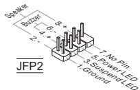
text_image
Speaker Butzer 8 + 6 - 4 + 12 - 7: No Pin 5. Power LED 3. Suspend LED 1. Ground JFP2シリアルポートコネクター: JCOM1
text_image
10: No Pin 8: CFS 6: DSR 4: DTR 2: SIN 9: R1 7: RTS 5: Ground 3: SOUT 1: DCDtext_image
1.0 Head Phone Detection 4. No pin 8. MIC Detection 2. PRESERCE 9. Head Phone L 5. SENSE-SEND 3. MLC R 1 MIC Ltext_image
10: USBOC 8: Ground 6: USB1+ 4: USB1- 2: VCC 9: No Pin 7: Ground 5: USBO+ 3: USB0- 1: VCCnatural_image
Line drawing of a rectangular mechanical component with a protruding bracket (no text or symbols)PCI Express x16スロット

PCI Express x1スロット
PCIスロット
natural_image
Isometric line drawing of a rectangular structural component with evenly spaced notches (no text or symbols)注意
Press DEL to enter SETUP
(キーを押して設定画面を呼び出す)
Integrated Peripherals (内蔵機能の設定)
text_image
CMOS Setup Utility - Copyright (C) 1985-2005, American Megatrends, Inc. Cell Menu Current CPU Frequency 2.20GHz (200x11) Current DRAM Frequency 800MHz ► CPU Specifications [Press Enter] AMD Cool'n'Quiet [Intol] Adjust CPU FSB Frequency (MHz) [200] Adjust CPU Ratio [Intol] Adjusted CPU Frequency (MHz) 2200 Adjust CPU-MB Ratio [Intol] Adjusted CPU-MB Frequency (MHz) 2000 EC Firmware [Normal] Advanced Clock Calibration [Disabled] MultiStep DC Booster [Disabled] ► MEMORY-2 [Press Enter] ► Advance DRAM Configuration [Press Enter] FSB/DRAM Ratio [Intol] Adjusted DRAM Frequency (MHz) 800 HT Link Speed [Intol] Adjust PCI-E Frequency (MHz) [100] CPU Voltage (U) [Intol] DRAM Voltage (U) [Intol] MD Voltage (U) [.214] Spread Spectrum [Enabled] T←→:Move Enter:Select +/-Value F10:Save ESC:Exit F1:General Help FB:Fail-Safe Defaults FB:Optimized Defaults Help Item CPU InformationCurrent CPU/DRAM Frequency (現在のCPU/ DRAM周波数)
text_image
Power Options Properties Power Schemes Advanced Hibernate UPS Select the power scheme with the most appropriate settings for this computer. Note that changing the settings below will modify the selected scheme. Power schemes Minimal Power Management Home/Office Desk Portable/Laptop Presentation Always On Minimal Power Management Max Battery Turn off Monitor: Never Turn off hard disks: Never System standby: Never System libemates: Never OK Cancel ApplyAdjust CPU FSB Frequency (MHz) (CPU FSB周波数を調整する)
CPU FSB 周波数を調整します。
CPU Voltage (V) (CPU電圧)
CPU電圧を調整します。
DRAM Voltage (V) (DRAM電圧)
メモリ電圧を調整します。
NB Voltage (V) (NB電圧)
ノースブリッジ電圧を調整します。