
B250M PROVDH - Motherboard MSI - Free user manual and instructions
Find the device manual for free B250M PROVDH MSI in PDF.
| Product Type | Motherboard |
| Brand | MSI |
| Model | B250M PROVDH |
| Form Factor | micro-ATX |
| Dimensions | 244 x 228 mm (9.6 x 9.0 inches) |
| Processor Socket | LGA1151 |
| Chipset | Intel® B250 |
| Supported Processors | Intel® Core™ i3/i5/i7, Pentium®, Celeron® (6th/7th Generation) |
| Memory Type | DDR4 |
| Number of Memory Slots | 4 |
| Maximum Memory Capacity | 64 GB |
| Supported Memory Frequencies | DDR4 2400/2133 MHz |
| PCIe Slots | 1 x PCIe 3.0 x16, 2 x PCIe 3.0 x1 |
| SATA Storage | 6 x SATA 6 Gb/s |
| M.2 Slot | 1 x M.2 (PCIe 3.0 x4 / SATA 6 Gb/s) |
| USB Ports (Rear Panel) | 2 x USB 2.0, 3 x USB 3.1 Gen1 Type-A, 1 x USB 3.1 Gen1 Type-C |
| USB Ports (Internal) | 2 x USB 2.0 (4 ports via headers), 1 x USB 3.1 Gen1 (2 ports) |
| Audio | Realtek ALC887, 7.1 channels |
| LAN | Realtek 8111H Gigabit Ethernet |
| Power Connectors | 1 x ATX 24-pin, 1 x ATX 8-pin |
| Fan Connectors | 1 x CPU fan (4-pin), 2 x system fan (4-pin) |
| Other Internal Connectors | TPM, chassis intrusion, serial port, parallel port, RGB LED, Thunderbolt |
| BIOS | AMI UEFI 64 Mb, M-Flash, Live Update 6 |
| Included Software | Command Center, Mystic Light, Super Charger, RAMDisk, X-Boost |
| Security | TPM, chassis intrusion detection, Clear CMOS |
Frequently Asked Questions - B250M PROVDH MSI
User questions about B250M PROVDH MSI
0 question about this device. Answer the ones you know or ask your own.
Ask a new question about this device
Download the instructions for your Motherboard in PDF format for free! Find your manual B250M PROVDH - MSI and take your electronic device back in hand. On this page are published all the documents necessary for the use of your device. B250M PROVDH by MSI.
USER MANUAL B250M PROVDH MSI
Thank you for purchasing the MSI^® H270M PRO-VDH/ B250M PRO-VDH motherboard. This User Guide gives information about board layout, component overview, BIOS setup and software installation.
Contents
Safety Information 2
Specifications 3
Rear I/O Panel 6
LAN Port LED Status Table 6
Overview of Components 7
CPU Socket 8
DIMM Slots 9
PCI_E1~3:PCIe Expansion Slots. 9
JFP1, JFP2: Front Panel Connectors 10
SATA1~6: SATA 6Gb/s Connectors 10
M2_1: M.2 Slot (Key M) 11
ATX_PWR1, CPU_PWR1: Power Connectors 11
JUSB2-3: USB 2.0 Connectors 12
JUSB1: USB 3.1 Gen1 Connector 12
CPU_FAN1, SYS_FAN1~2: Fan Connectors 13
JTPM1: TPM Module Connector. 14
JCI1: Chassis Intrusion Connector 14
JAUD1:Front Audio Connector 15
JCOM1: Serial Port Connector. 15
JLPT1: Parallel Port Connector 15
JLED1: RGB LED connector 16
JBAT1: Clear CMOS (Reset BIOS) Jumper. 16
Onboard LEDs. 17
BIOS Setup 18
EnteringBIOS Setup. 18
ResettingBIOS 19
Updating BIOS 19
Software Description 20
Installing Windows 7/8.1/10 20
Installing Drivers 20
Installing Utilities 20
Safety Information
- The components included in this package are prone to damage from electrostatic discharge (ESD). Please adhere to the following instructions to ensure successful computer assembly.
- Ensure that all components are securely connected. Loose connections may cause the computer to not recognize a component or fail to start.
- Hold the motherboard by the edges to avoid touching sensitive components.
- It is recommended to wear an electrostatic discharge (ESD) wrist strap when handling the motherboard to prevent electrostatic damage. If an ESD wrist strap is not available, discharge yourself of static electricity by touching another metal object before handling the motherboard.
- Store the motherboard in an electrostatic shielding container or on an anti-static pad whenever the motherboard is not installed.
- Before turning on the computer, ensure that there are no loose screws or metal components on the motherboard or anywhere within the computer case.
- Do not boot the computer before installation is completed. This could cause permanent damage to the components as well as injury to the user.
- If you need help during any installation step, please consult a certified computer technician.
-
Always turn off the power supply and unplug the power cord from the power outlet before installing or removing any computer component.
-
Keep this user guide for future reference.
-
Keep this motherboard away from humidity.
-
Make sure that your electrical outlet provides the same voltage as is indicated on the PSU, before connecting the PSU to the electrical outlet.
- Place the power cord such a way that people can not step on it. Do not place anything over the power cord.
All cautions and warnings on the motherboard should be noted.
- If any of the following situations arises, get the motherboard checked by service personnel:
Liquid has penetrated into the computer.
The motherboard has been exposed to moisture.
- The motherboard does not work well or you can not get it work according to user guide.
The motherboard has been dropped and damaged.
The motherboard has obvious sign of breakage.
- Do not leave this motherboard in an environment above 60^ (140^) , it may damage the motherboard.
Specifications
Continued on next page
| CPU | Supports 6th/ 7th Gen Intel® Core™ i3/i5/i7 processors, and Intel® Pentium® and Celeron® processors for Socket LGA1151 |
| Chipset Intel | ®H270/ B250 Chipset |
| Memory | 4x DDR4 memory slots, support up to 64GB 7th Gen processors support DDR4 2400/ 2133 MHz* 6th Gen processors support DDR4 2133 MHz* Dual channel memory architecture Supports Intel® Extreme Memory Profile (XMP)** Please refer www.msi.com for more information on compatible memory. ** DDR4 memory modules can only run at maximum of 2400 MHz for 7th Gen processors and 2133 MHz for 6th Gen processors on XMP mode. |
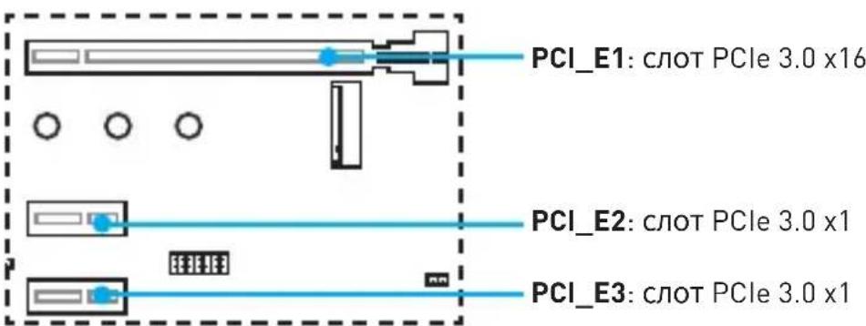
| Expansion Slots | 1x PCIe 3.0 x16 slot (supports x16 mode) 2x PCIe 3.0 x1 slots |
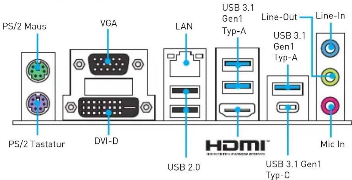
| Onboard Graphics | 1x HDMI port, supports a maximum resolution of 4096x2160@24Hz, 2560x1600@60Hz 1x DVI-D port, supports a maximum resolution of 1920x1200@60Hz 1x VGA port, supports a maximum resolution of 2048x1536@50Hz, 2048x1280@60Hz, 1920x1200@60Hz |
| Storage | Intel® H270/ B250 Chipset 6x SATA 6Gb/s ports 1x M.2 slot (Key M) Supports up to PCIe 3.0 x4 and SATA 6Gb/s Supports 2242/ 2260 /2280 storage devices In@ptane™ Memory Ready H270 supports RAID 0, RAID1, RAID 5 and RAID 10 for SATA storage devices |
| USB | Intel® H270/ B250 Chipset 6x USB 3.1 Gen1 (SuperSpeed USB) ports (3 Type-A & 1 Type-C ports on the back panel, 2 ports available through the internal USB connector) 6x USB 2.0 (High-speed USB) ports (2 ports on the back panel, 4 ports available through the internal USB connector) |
| Audio | Realtek® ALC887 Codec 7.1-Channel High Definition Audio |
| LAN 1x Realtek | ® 8111H Gigabit LAN controller |
Continued from previous page
| Back Panel Connectors | • 1x PS/2 keyboard port • 1x PS/2 mouse port • 1x HDMIbrt • 1x VGA port • 1x DVI-D port • 1x LAN (RJ45) port • 2x USB 2.0 Type-A ports • 3x USB 3.1 Gen1 Type-A ports • 1x USB 3.1 Gen1 Type-C port • 3x audio jacks |
| Internal Connectors | • 1x 24-pin ATX main power connector • 1x 8-pin ATX 12V power connector • 6x SATA 6Gb/s connectors • 2x USB 2.0 connectors (supports additional 4 USB 2.0 ports • 1x USB 3.1 Gen1 connector (supports additional 2 USB 3.1 Gen1 ports) • 1x 4-pin CPU fan connector • 2x 4-pin system fan connectors • 1x Front panel audio connector • 2x Front panel connectors • 1x TPM module connector • 1x Chassis Intrusion connector • 1x Serial port connector • 1x Parallel port connector • 1x RGB LED connecotr • 1x TBT connector • 1x Clear CMOS jumper |
| I/O Controller NUVOTON NCT6795 Controller Chip | |
| Hardware Monitor | • CPU/System temperature detection • CPU/System fan speed detection • CPU/System fan speed control |
| Form Factor | • m-ATX Form Factor • 9.6 in. x 9.0 in. (24.4 cm x 22.8 cm) |
| BIOS Features | • 1x 64 Mb flash • UEFI AMI BIOS • ACPI 5.0, PnP 1.0a, SM BIOS 2.8 • Multi-language |
Continued on next page
Continued from previous page
| Software | ● Drivers ● COMMAND CENTER ● LIVE UPDATE 6 ● FAST BOOT ● SUPER CHARGER ● MYSTIC LIGHT ● RAMDISK ● X-BOOST ● MSI SMART TOOL ● NETWORK GENIE ● InteXtreme Tuning Utility ● NortoSecurity ● Google Chrom.Goagle Toolbar, Google Drive ● CPU-Z MSI GAMING |
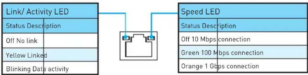
Rear I/O Panel

LAN Port LED Status Table
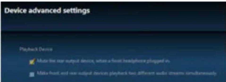
Audio 7.1-channel Configuration
To configure 7.1-channel audio, you have to connect front audio I/O module to JAUD1 connector and follow the below steps.
- Click on the Realtek HD Audio Manager > Advanced Settings to open the dialog below.
-
Select Mute the rear output device, when a front headphone plugged in.
-
Plug your speakers to audio jacks on rear and front I/O panel. When you plug into a device at an audio jack, a dialogue window will pop up asking you which device is current connected.
Overview of Components
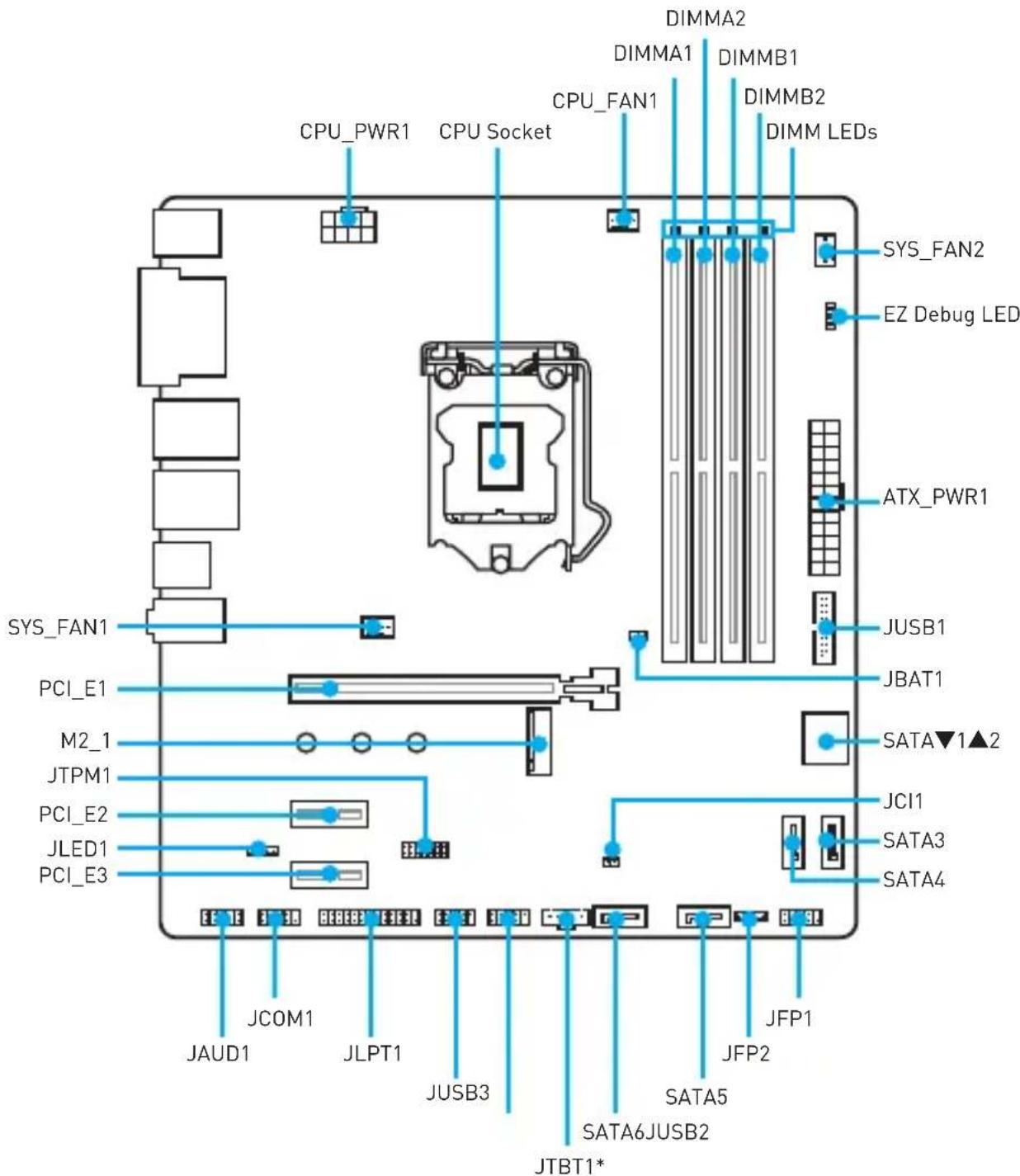
* JTBT1 is used to connect a specific card.
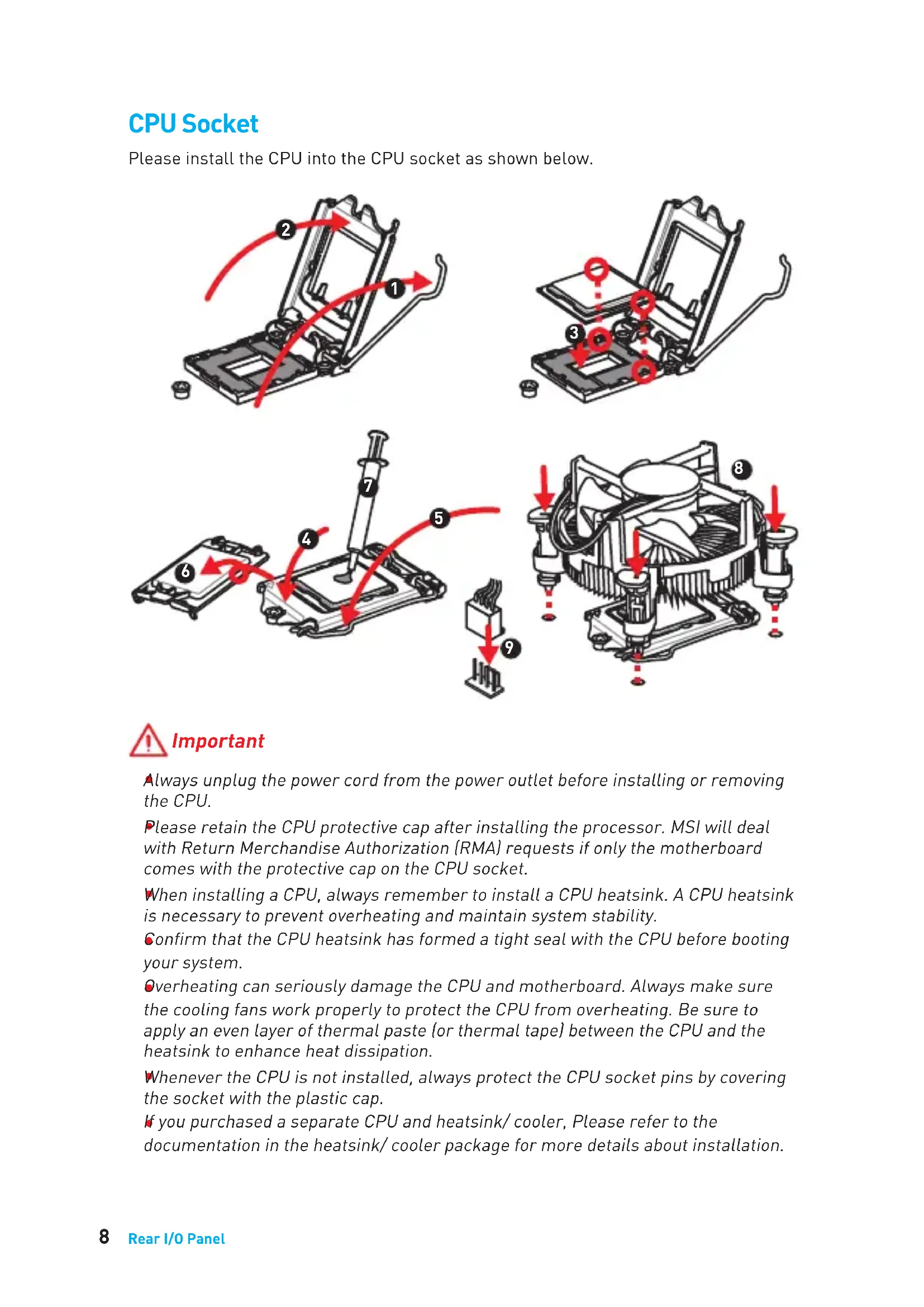
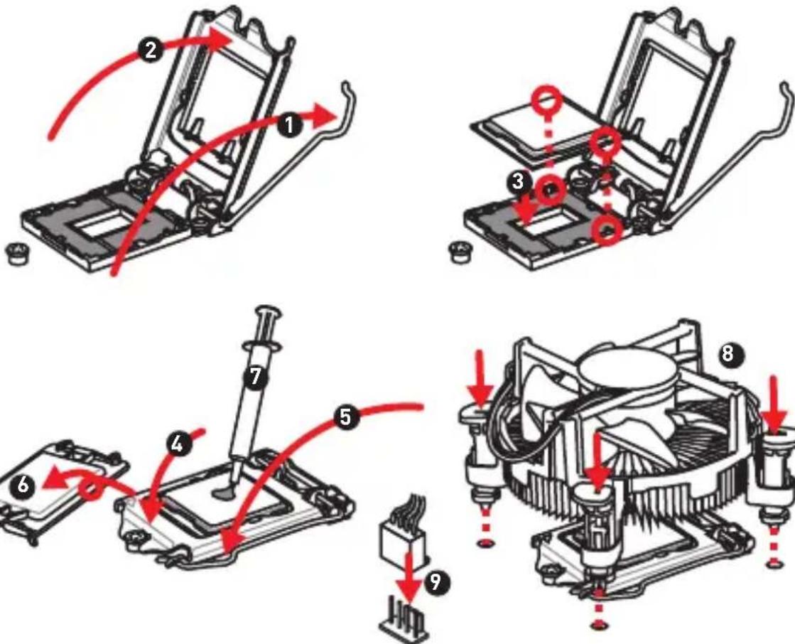
CPU Socket
Please install the CPU into the CPU socket as shown below.
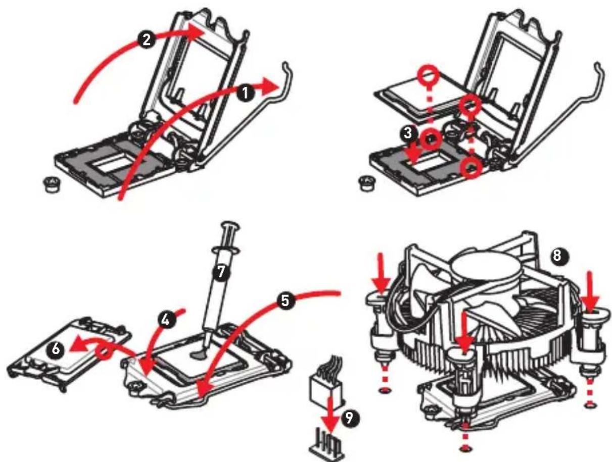

Important
Always unplug the power cord from the power outlet before installing or removing the CPU.
Please retain the CPU protective cap after installing the processor. MSI will deal with Return Merchandise Authorization (RMA) requests if only the motherboard comes with the protective cap on the CPU socket.
When installing a CPU, always remember to install a CPU heatsink. A CPU heatsink is necessary to prevent overheating and maintain system stability.
Confirm that the CPU heatsink has formed a tight seal with the CPU before booting your system.
Overheating can seriously damage the CPU and motherboard. Always make sure the cooling fans work properly to protect the CPU from overheating. Be sure to apply an even layer of thermal paste (or thermal tape) between the CPU and the heatsink to enhance heat dissipation.
Whenever the CPU is not installed, always protect the CPU socket pins by covering the socket with the plastic cap.
If you purchased a separate CPU and heatsink/ cooler, Please refer to the documentation in the heatsink/ cooler package for more details about installation.
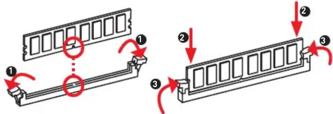
DIMM Slots
Please install the memory module into the DIMM slot as shown below.
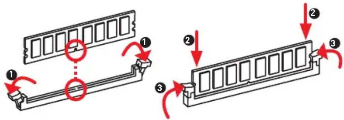

Important
To boot up the system successfully, always insert the memory module into DIMMA2 first.
Due to chipset resource usage, the available capacity of memory will be a little less than the amount of installed.
Please note that the maximum capacity of addressable memory is 4GB or less for 32-bit Windows OS due to the memory address limitation. Therefore, we recommended that you to install 64-bit Windows OS if you want to install more than 4GB memory on the motherboard.
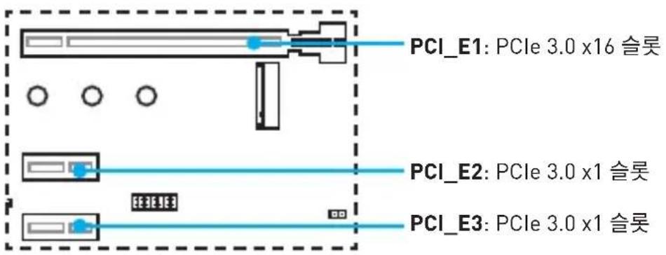
PCI_E1~3: PCIe Expansion Slots
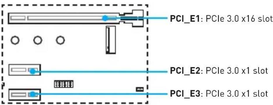

Important
When adding or removing expansion cards, always turn off the power supply and unplug the power supply power cable from the power outlet. Read the expansion card's documentation to check for any necessary additional hardware or software changes.
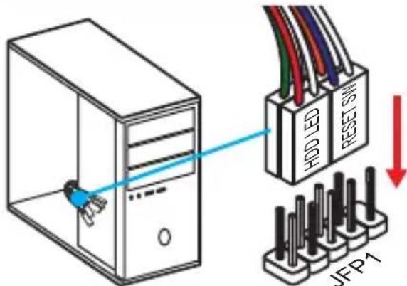
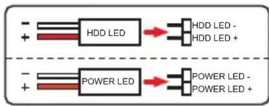
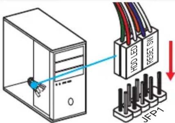
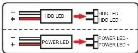
JFP1, JFP2: Front Panel Connectors
These connectors connect to the switches and LEDs on the front panel.
| JFP1 2 10 1 9 | 1 H | DD LED + 2 Power LED | + | |
| 3 H | DD LED - 4 Power LED | - | ||
| 5 Reset Switch 6 Power Switch | ||||
| 7 Reset Switch 8 Power Switch | ||||
| 9 Reserved 10 No Pin | ||||
| 1 JFP2 | 1 S | Speaker - 2 Buzzer + | ||
| 3 | Buzzer - | 4 Speaker + |
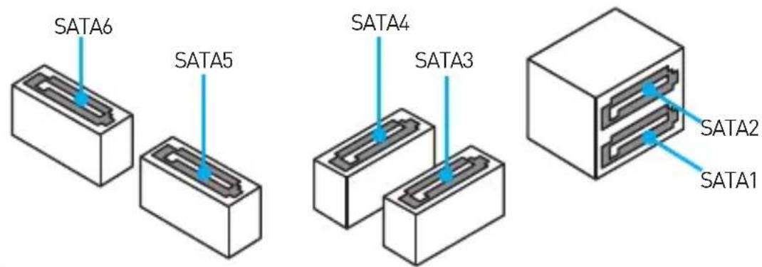
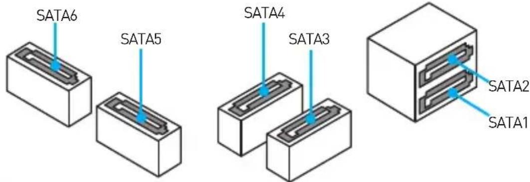
SATA1~6: SATA 6Gb/s Connectors
These connectors are SATA 6Gb/s interface ports. Each connector can connect to one SATA device.
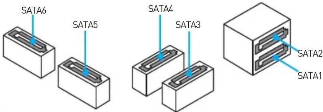

Important
Please do not fold the SATA cable at a 90-degree angle. Data loss may result during transmission otherwise.
SATA cables have identical plugs on either sides of the cable. However, it is recommended that the flat connector be connected to the motherboard for space saving purposes.
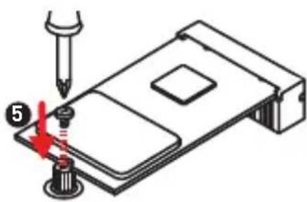
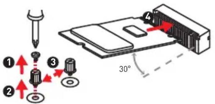
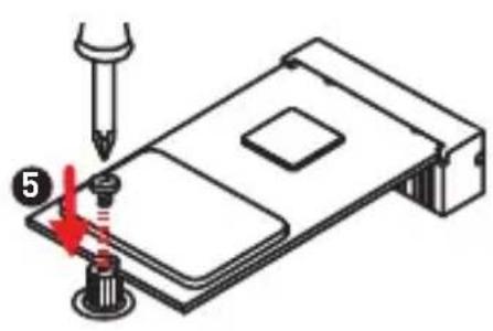
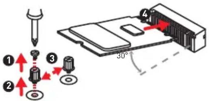
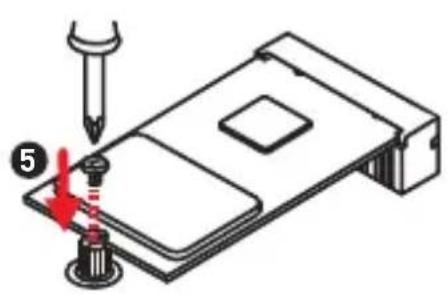
M2_1: M.2 Slot (Key M)
Please install the M.2 solid-state drive (SSD) into the M.2 slot as shown below.
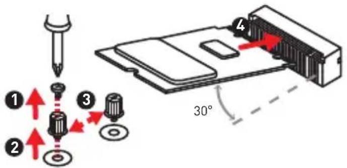

Important
Intel® RST only supports PCIe M.2 SSD with UEFI ROM, does not support Legacy ROM.
ATX_PWR1, CPU_PWR1: Power Connectors
These connectors allow you to connect an ATX power supply.
| 12 24 1 13 ATX_PWR1 | 1 + 3.3V 13 +3.3V | ||
| 2 + 3.3V 14 -12V | |||
| 3 Ground 15 Ground | |||
| 4 +5V 16 PS-ON# | |||
| 5 Ground 17 Ground | |||
| 6 +5V 18 Ground | |||
| 7 Ground 19 Ground | |||
| 8 PWR OK 20 Res | |||
| 9 5 VSB 21 +5V | |||
| 10 + 12V 22 +5V | |||
| 11 + 12V 23 +5V | |||
| 12 + 3.3V 24 Ground |
| CPU_PWR1 | 1 Ground 5 +12V | ||
| 2 Ground 6 +12V | |||
| 3 Ground 7 +12V | |||
| 4 Ground 8 +12V |

Important
Make sure that all the power cables are securely connected to a proper ATX power supply to ensure stable operation of the motherboard.
JUSB2~3: USB 2.0 Connectors
These connectors allow you to connect USB 2.0 ports on the front panel.
| 2 10 1 9 | 1 VCC 2 VCC | ||
| 3 USB0- 4 USB1- | |||
| 5 USB0+ 6 USB1+ | |||
| 7 Ground 8 Ground | |||
| 9 No Pin 10 10 NC |
Important
- Note that the VCC and Ground pins must be connected correctly to avoid possible damage.
- In order to recharge your iPad,iPhone and iPod through USB ports, please install MSI® SUPER CHARGER utility.
JUSB1: USB 3.1 Gen1 Connector
This connector allows you to connect USB 3.1 Gen1 ports on the front panel.
| 10 11 20 | 1 Power 11 USB2.0+ | ||
| 2 USB3_RX_DN 12 USB2.0- | |||
| 3 USB3_RX_DP 13 Ground | |||
| 4 Ground 14 USB3_TX_C_DP | |||
| 5 USB3_TX_C_DP 15 | USB3_TX_C_DP | ||
| 6 | USB3_TX_C_DP 16 | Ground | |
| 7 Ground 17 | USB3_RX_DP | ||
| 8 USB2.0- | 18 USB3_RX_DP | ||
| 9 | USB2.0+ | 19 Power | |
| 10 | NC | 20 No Pin |
Important
Note that the Power and Ground pins must be connected correctly to avoid possible damage.
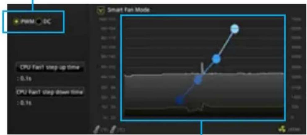
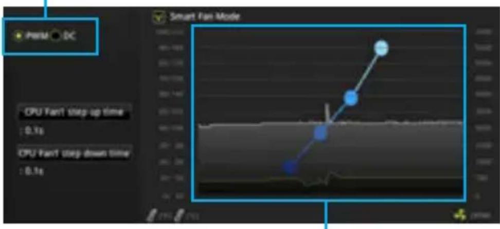
CPU_FAN1, SYS_FAN1~2: Fan Connectors
Fan connectors can be classified as PWM (Pulse Width Modulation) Mode and DC Mode. PWM Mode fan connectors provide constant 12V output and adjust fan speed with speed control signal. DC Mode fan connectors control fan speed by changing voltage. Therefore, when you plug a 3-pin (Non-PWM) fan to a PWM Mode fan connector, the fan speed will be always maintained at 100% , and that could be noisy.
You can switch between PWM mode and DC mode and adjust fan speed in BIOS > HARDWARE MONITOR.
Select PWM mode or DC mode
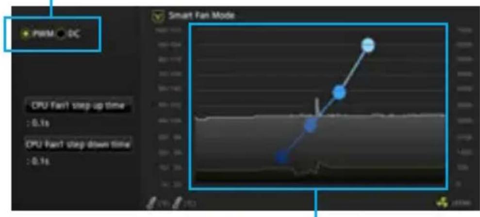
There are gradient points of the fan speed that allow you to adjust fan speed in relation to CPU temperature.

Important
Make sure fans are working properly after switching the PWM/ DC mode.
JTPM1: TPM Module Connector
This connector is for TPM (Trusted Platform Module). Please refer to the TPM security platform manual for more details and usages.
| 2 14 1 13 | 1 LPC Clock 2 3V Standby power | ||
| 3 LPC Reset 4 3.3V Power | |||
| 5 LPC address & data pin0 6 Serial IRQ | |||
| 7 LPC address & data pin1 8 5V Power | |||
| 9 LPC address & data pin2 10 No Pin | |||
| 11 LPC address & data pin3 12 Ground | |||
| 13 | LPC Frame 14 Ground |
JCl1: Chassis Intrusion Connector
This connector allows you to connect the chassis intrusion switch cable.

Normal
(default)

Trigger the chassis
intrusion event
Using chassis intrusion detector
- Connect the JCI1 connector to the chassis intrusion switch/ sensor on the chassis.
- Close the chassis cover.
- Go to BIOS > Security > Chassis Intrusion Configuration.
- Set Chassis Intrusion to Enabled.
- Press F10 to save and exit and then press the Enter key to select Yes.
- Once the chassis cover is opened again, a warning message will be displayed on screen when the computer is turned on.
Resetting the chassis intrusion warning
- Go to BIOS > Security > Chassis Intrusion Configuration.
- Set Chassis Intrusion to Reset.
- Press F10 to save and exit and then press the Enter key to select Yes.
JAUD1: Front Audio Connector
This connector allow you to connect audio jacks on the front panel.
| 2 10 1 9 | 1 MIC L 2 Ground | ||
| 3 MIC R 4 NC | |||
| 5 Head Phone R 6 MIC Detection | |||
| 7 SENSE_SEND 8 No Pin | |||
| 9 Head Phone L 10 Head Phone Detection |
JCOM1: Serial Port Connector
This connector allows you to connect the optional serial port with bracket.
| 2 10 1 9 | 1 DCD 2 SIN | ||
| 3 SOUT 4 DTR | |||
| 5 | Ground | 6 D$R | |
| 7 | RTS | 8 CTS | |
| 9 RI | 10 No Pin |
JLPT1: Parallel Port Connector
This connector allows you to connect the optional parallel port with bracket.
| 2 1 26 | |||||
| 1 | RSTB# | 2 | AFD# | 3 | PRND0 |
| 4 | ERR# | 5 | PRND1 | 6 | PINIT# |
| 7 | PRND2 | 8 | LPT_SLIN# | 9 | PRND3 |
| 10 | Ground | 11 | PRND4 | 12 | Ground |
| 13 | PRND5 | 14 | Ground | 15 | PRND6 |
| 16 | Ground | 17 | PRND7 | 18 | Ground |
| 19 | ACK# | 20 | Ground | 21 | BUSY |
| 22 | Ground | 23 PE 24 Ground | |||
| 25 | SLCT | 26 No Pin | |||
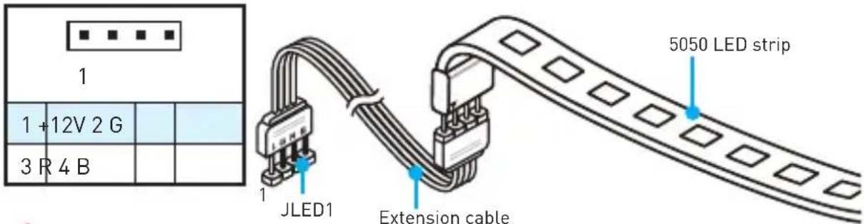
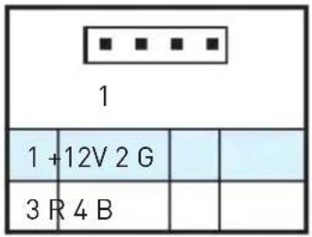
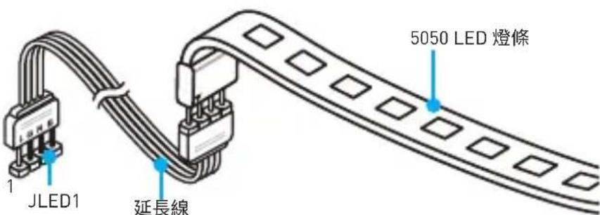
JLED1: RGB LED connector
These connectors allow you to connect the 5050 RGB LED strips.
Important
This connector supports 5050 RGB multi-color LED strips (12V/G/R/B) with the maximum power rating of 3A (12V). Please keeping the LED strip shorter than 2 meters to prevent dimming.
Always turn off the power supply and unplug the power cord from the power outlet before installing or removing the RGB LED strip.
Please use the LED Effect of GAMING APP to adjust, calibrate and control the LED light, refer to the Software section for details.
JBAT1: Clear CMOS (Reset BIOS) Jumper
There is CMOS memory onboard that is external powered from a battery located on the motherboard to save system configuration data. If you want to clear the system configuration, set the jumpers to clear the CMOS memory.

Keep Data (default)

Clear CMOS/ Reset BIOS
Resetting BIOS to default values
- Power off the computer and unplug the power cord
- Use a jumper cap to short JBAT1 for about 5-10 seconds.
- Remove the jumper cap from JBAT1.
- Plug the power cord and power on the computer.
Onboard LEDs
DIMM LEDs - indicate the memory modules are installed.
PCIe x16 slot LED - indicates the PCIe x16 slots status. [Red] - x16 mode.
[White] - X8, X4, X1 mode.
EZ Debug LED
These LEDs indicate the status of the motherboard.
CPU - indicates CPU is not detected or fail.
DRAM - indicates DRAM is not detected or fail.
VGA - indicates GPU is not detected or fail.
- BOOT - indicates booting device is not detected or fail.
BIOS Setup
The default settings offer the optimal performance for system stability in normal conditions. You should always keep the default settings to avoid possible system damage or failure booting unless you are familiar with BIOS.

Important
BIOS items are continuous update for better system performance. Therefore, the description may be slightly different from the latest BIOS and should be held for reference only. You could also refer to the HELP information panel for BIOS item description.
The pictures in this chapter are for reference only and may vary from the product you purchased.
Entering BIOS Setup
Please refer the following methods to enter BIOS setup.
- Press Delete key, when the Press DEL key to enter Setup Menu, F11 to enter Boot Menu message appears on the screen during the boot process.
- Use MSI FAST BOOT application. Click on GO2BIOS button and choose OK. The system will reboot and enter BIOS setup directly.
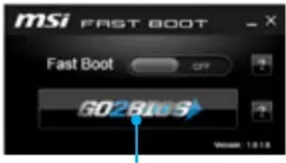
Click on GO2BIOS
Function key
| Key Function Key Function | |||
| F1 General Help F2 Add/ Remove a favorite | item | ||
| F3 Enter Favorites menu F4 Enter CPU Specifications | |||
| F5 Enter Memory-Z menu F6 Load optimized defaults | |||
| F7 | Switch between Advanced mode and EZ mode | F8 | Load Overclocking Profile |
| F9 | Save Overclocking Profile | F10 | Save Change and Reset* |
| F12 | Take a screenshot and save it to USB flash drive (FAT/ FAT32 format only). | ||
- When you press F10, a confirmation window which provides the modification information appears. Select between Yes or No to confirm your choice.
Resetting BIOS
You might need to restore the default BIOS setting to solve certain problems. There are several ways to reset BIOS:
- Go to BIOS and press F6 to load optimized defaults.
- Short the Clear CMOS jumper on the motherboard.

Important
Please refer to the Clear CMOS jumper section for resetting BIOS.
Updating BIOS
Updating BIOS with M-FLASH
Before updating:
Please download the latest BIOS file that matches your motherboard model from MSI website. And then save the BIOS file into the USB flash drive.
Updating BIOS:
- Insert the USB flash drive that contains the update file into the computer.
- Reboot the system, and then press Del key to enter the BIOS Setup during POST.
- Go to BIOS > M-FLASH > Select one file to update BIOS and ME, select a BIOS file to perform the BIOS update process.
- After the flashing process is 100% complete, the system will reboot.
Updating the BIOS with Live Update 6
Before updating:
Make sure the LAN driver is already installed and the internet connection is set properly.
Updating BIOS:
- Install and launch MSI LIVE UPDATE 6.
- Select Manual scan.
- Check MB BIOS box and click on Scan button.
- Select the MB BIOS and click on icon to download and install the latest BIOS file.
- Click Next and choose In Windows mode. And then click Next and Start to start updating BIOS.
- After the flashing process is 100% completed, the system will restart automatically.
Software Description
Installing Windows® 7/8.1/10
- Power on the computer.
- Insert the Windows 7 / 8.1 / 10 disc into your optical drive.
Note: Due to chipset limitation, during the Windows® 7 installation process, USB optical drives and USB pen drives are not supported. You can use MSI Smart Tool to install Windows® 7.
- Press the Restart button on the computer case.
- For windows 8.1/ 10, skip this step. For Windows 7, access the BIOS menu Advanced > Windows OS Configuration > Windows 7 Installation and set the item to enabled, save changes and restart.
Note: It is suggested to plug in your USB Keyboard/USB Mouse to the leftmost USB port when installing Windows 7.
- Press F11 key during the computer POST (Power-On Self Test) to get into Boot Menu.
- Select your optical drive from the Boot Menu.
- Press any key when screen shows Press any key to boot from CD or DVD... message.
- Follow the instructions on the screen to install Windows 7/8.1/10.
Installing Drivers
- Start up your computer in Windows 7/8.1/10.
- Insert MSI Driver Disc into your optical drive.
- The installer will automatically appear and it will find and list all necessary drivers.
- Click Install button.
- The software installation will then be in progress, after it has finished it will prompt you to restart.
- Click OK button to finish.
- Restart your computer.
Installing Utilities
Before you install utilities, you must complete drivers installation.
- Insert MSI Driver Disc into your optical drive.
- The installer will automatically appear.
- Click Utilities tab.
- Select the utilities you want to install.
- Click Install button.
- The utilities installation will then be in progress, after it has finished it will prompt you to restart.
- Click OK button to finish.
- Restart your computer.
MSI® H270M PRO-VDH/B250M PRO-VDH éinebrd to kiphe
主串员,BIOS 电电电电电电电电电电电电电电电电电电电电电电电电电电电电电电电电电电电电电电电电电电电电电电电电电电电电电电电电电电电电电电电电电电电电电电电电电电电电电电电电电电电
目录
Anexti 2
3
I/0
LAN foTLED 6
7
CPU 系列 ..... 8
DIMM 合吴 9
PCI_E1~3:PCIe告首
JFP1,JFP2: 10
SATA1~6:SATA 6Gb/s封装器 10
M2_1: M.2 合吴 (Key M) 11
ATX_PWR1, CPU_PWR1: 推广商用机 ..... 11
JUSB2-3: USB 2.0 封部器 ..... 12
JUSB1: USB 3.1 Gen1 Konkter 12
CPU_FAN1, SYS_FAN1~2: 帮助代码 ..... 13
JTPM1: TPM 14
JCI1: 14
JAUD1: 15
JCOM1: 15
JLPT1: 费尔莫托克图. 15
JusMoRiJ 4GB HnEeMouL JusS
iHaRnEeUyHJ.4G016M
Windows OS 論點點點點點點點點點點點點點點點點點點點點點點點點點點點點點點點點點點點點點點點點點點點點點點點點點點點點點點點點點點點點點點點點點點點點點點點點點點點點點點點點點點點點點點點點點點點點點點點點點點點點
PCI_E1~3: PCIe 創造者

要
| JFP2 | 1 S | speaker - 2 Buzzer + | ||
| 3 | Buzzer - | 4 S | speaker + |
SATA1~6:SATA 6Gb/s 芯网
Ie 6Gb/s Ie Tte Hs foetl.

责
SATA KeIbB 90DorKJtMae.其FgW,TcHsCzEITeHa HsHgLdS HsHnLi
SATA KeIbB of the Aotok moTbeundetendilh pLrueo hasiJtAn GcAn Jelakou wihhe PpLk TckteToe
MeIn BdoTh eongeh fke to qanlhdni.
M2_1: M.2 合吴 (Key M)
M.2 solid-state drive (SSD) to tellhsiitigb
中
Intel®RST是UEFI ROM PCIe M.2 SSD的可息用器,ROM是可息用器
ATX_PWR1, CPU_PWR1: 推广封装电路
IeKnTtRtoaouhAOTXJrJnQgJstciToenellHs
| 12 24 1 13 ATX_PWR1 | 1 + 3.3V 13 +3.3V | ||
| 2 + 3.3V 14 -12V | |||
| 3 Ground 15 Ground | |||
| 4 +5V 16 PS-ON# | |||
| 5 Ground 17 Ground | |||
| 6 +5V 18 Ground | |||
| 7 Ground 19 Ground | |||
| 8 PWR OK 20 Res | |||
| 9 5 VSB 21 +5V | |||
| 10 + 12V 22 +5V | |||
| 11 + 12V 23 +5V | |||
| 12 + 3.3V 24 Ground |
| CPU_PWR1 | 1 Ground 5 +12V | ||
| 2 Ground 6 +12V | |||
| 3 Ground 7 +12V | |||
| 4 Ground 8 +12V |
☆
MnTATX 10
JUSB2~3: USB 2.0 썸본지
i 2.0 fo3
| 2 10 1 9 | 1 VCC 2 VCC | |||
| 3 USB0- 4 USB1- | ||||
| 5 USB0+ 6 USB1+ | ||||
| 7 | Ground | 8 | Ground | |
| 9 No Pin 10 | NC |
中
| 10 11 20 | 1 Power 11 USB2.0+ | ||
| 2 USB3_RX_DN 12 USB2.0- | |||
| 3 USB3_RX_DP 13 Ground | |||
| 4 Ground 14 USB3_TX_C_DP | |||
| 5 USB3_TX_C_DP 15 | USB3_TX_C_DP | ||
| 6 | USB3_TX_C_DP 16 | Ground | |
| 7 Ground 17 | USB3_RX_DP | ||
| 8 USB2.0- | 18 USB3_RX_DP | ||
| 9 | USB2.0+ | 19 Power | |
| 10 | NC | 20 No Pin |
中
前用及其云运理于,
PWM MoT PwM 12V of 12V of 12V of 12V of 12V of 12V of 12V of 12V of 12V of 12V of 12V of 12V of 12V of 12V of 12V of 12V of 12V of 12V of 12V of 12V of 12Vof 12V of 12V of 12V of 12V of 12V of 12V of 12V of 12V of 12V of 12V of 12V of 12V of 12V of 12V of 12V of 12V of 12V of 12V of 12V of 12V OF 12V OF 12V OF 12V OF 12V OF 12V OF 12V OF 12V OF 12V OF 12V OF 12V OF 12V OF 12V OF 12V OF 12V OF 12V OF 12V OF 12V OF 12V OF 12V OF 12VOF 12V OF 12V OF 12V OF 12V OF 12V OF 12V OF 12V OF 12V OF 12V OF 12V OF 12V OF 12V OF 12V OF 12V OF 12V OF 12V OF 12V OF 12V OF 12V OF 12V Of 12 V Of 12 V Of 12 V Of 12 V Of 12 V Of 12 V Of 12 V Of 12 V Of 12 V Of 12 V Of 12 V Of 12 V Of 12 V Of 12 V Of 12 V Of 12 V Of 12 V Of 12 V Of 12 V Of 12 V Of 12
PWM 03D 型封装电路
| CPU_FAN1 | |||
| 1 | Ground 2 +12V | ||
| 3 | Sense 4 | Speed Control Signal | |
DC moD 300000000000000000000000000000000000000000
| 1 SYS_FAN1 | 1 SYS_FAN2 | ||
| 1 G | round 2 | Voltage Control | |
| 3 S | ense 4 NC | ||
遍马德朝宣尚默高
PWM MoTd wD DC MoT d sAeH eep Tn HcHb BIOs > HARDWARE MONITOR Ro Ieundohr PAnh Nto h tioh n.
PWM MoT D DC MoT
CPU运上都如拉,幸土歌为断络,能当

中
PWM/DC 2015年版
JTPM1: TPM모들 키 nkTe
Ie TPM (Trusted Platform Module) moed enellednla. Jeeh h nong and sucr be TPM bo an pletf selming r to cto hio
| 2 14 1 13 | 1 LPC Clock 2 3V Standby power | ||
| 3 LPC Reset 4 3.3V Power | |||
| 5 LPC address & data pin0 6 Serial IRQ | |||
| 7 LPC address & data pin1 8 5V Power | |||
| 9 LPC address & data pin2 10 No Pin | |||
| 11 LPC address & data pin3 12 Ground | |||
| 13 | LPC Frame 14 Ground |
JCI1: 生成时钟的封装电路
iKETeTae 3n

印证
[基因的表达]

新社刊登
新社刊登时志
- JCI1knkeTto 5i
- 电电电电电电电电电电电电电电电电电电电电电电电电电电电电电电电电电电电电电电电电电电电电电电电电电电电电电电电电电电电电电电电电电电电电电电电电电电电电电电电电电电电电电电电
- BIOS > Security(보안) > Chassis Intrusion Configuration(내지 썸일구성)로 이동화发展壮大.
- Chassis Intrusion(新市)的登录将被禁用。
- F10 kui nre rre ene gie ege hag oohy hni. Enter kui nre hyns h Yes y
- 6
新社「
- BIOS > Security(보안) > Chassis Intrusion Configuration(내선 키일 채성)로 이동화发展壮大.
- Chassis Intrusion(新社き広)をReset(リチ)に用設定態態。
- F10 kii t r i . Enter kii t n nn h Yes te
JAUD1: 전선 오리오 키没钱지
iKnTto 1
| 2 10 1 9 | 1 MIC L 2 Ground | ||
| 3 MIC R 4 NC | |||
| 5 Head Phone R 6 MIC Detection | |||
| 7 SENSE_SEND 8 No Pin | |||
| 9 Head Phone L 10 Head Phone Detection |
JCOM1: 舰の上部は子は
Ie KInkTeBraKtJiHsOhyoHJyHJyHJyHJyHJyHJyHJyHJyHJyHJyHJyHJyHJyHJyHJyHJyHJyHJyHJyHJyHJyHJyHJyHJyHJyHJyHJyHJyHJyHJyHJyHJyHJyHJy
| 2 10 1 9 | 1 DCD 2 SIN | ||
| 3 SOUT 4 DTR | |||
| 5 | Ground | 6 D$R | |
| 7 | RTS | 8 CTS | |
| 9 RI | 10 No Pin |
JLPT1: 迪拉贝莫巨兵团
iKETeE 1
| 2 1 26 | |||||
| 1 | RSTB# | 2 | AFD# | 3 | PRND0 |
| 4 | ERR# | 5 | PRND1 | 6 | PINIT# |
| 7 | PRND2 | 8 | LPT_SLIN# | 9 | PRND3 |
| 10 | Ground | 11 | PRND4 | 12 | Ground |
| 13 | PRND5 | 14 | Ground | 15 | PRND6 |
| 16 | Ground | 17 | PRND7 | 18 | Ground |
| 19 | ACK# | 20 | Ground | 21 | BUSY |
| 22 | Ground | 23 PE 24 Ground | |||
| 25 | SLCT | 26 No Pin | |||
JLED1: RGB LED 친nexу
| 10 11 20 | 1 Power 11 USB2.0+ | ||
| 2 USB3_RX_DN 12 USB2.0- | |||
| 3 USB3_RX_DP 13 Ground | |||
| 4 Ground 14 USB3_TX_C_DP | |||
| 5 USB3_TX_C_DP 15 | USB3_TX_C_DP | ||
| 6 USB3_TX_C_DP | 16 Ground | ||
| 7 Ground 17 USB3_RX_DP | |||
| 8 USB2.0- 18 USB3_RX_DP | |||
| 9 USB2.0+ | 19 | Power | |
| 10 NC | 20 No Pin |
Important
| 2 10 1 9 | 1 MIC L 2 Ground | ||
| 3 MIC R 4 NC | |||
| 5 Head Phone R 6 MIC Detection | |||
| 7 SENSE_SEND 8 No Pin | |||
| 9 Head Phone L 10 Head Phone Detection |
ATX PWR1, CPU PWR1: Stromanschlüsse 11
JUSB2-3: USB 2.0 Anschlisse 12
JUSB1: USB 3.1 Gen1 Anschluss 12
Continued from previous page
Continued from previous page
| BIOS Funktionen | 1x 64 Mb Flash UEFI AMI BIOS ACPI 5.0, PnP 1.0a, SM BIOS 2.8 Mehrsprachenunterstützung |
| Software | Treiber COMMAND CENTER LIVE UPDATE 6 FAST BOOT SUPER CHARGER MYSTIC LIGHT RAMDISK X-BOOST MSI SMART TOOL NETWORK GENIE InteExtreme Tuning Utility NortoSecurity Google ChromGoogle Toolbar, Google Drive CPU-Z MSI GAMING |
Rückseite E/A
JFP1, JFP2: Frontpanel-Anschlüsse
SATA1~6: SATA 6Gb/s Anschlüsse
JUSB2~3: USB 2.0 Anschlüsse
| 10 11 20 | 1 Power 11 USB2.0+ | ||
| 2 USB3_RX_DN 12 USB2.0- | |||
| 3 USB3_RX_DP 13 Ground | |||
| 4 Ground 14 USB3_TX_C_DP | |||
| 5 USB3_TX_C_DP 15 | USB3_TX_C_DP | ||
| 6 | USB3_TX_C_DP 16 | Ground | |
| 7 Ground 17 | USB3_RX_DP | ||
| 8 USB2.0- | 18 USB3_RX_DP | ||
| 9 | USB2.0+ | 19 Power | |
| 10 | NC | 20 No Pin |

Wichtig
| 2 10 1 9 | 1 MIC L 2 Ground | ||
| 3 MIC R 4 NC | |||
| 5 Head Phone R 6 MIC Detection | |||
| 7 SENSE_SEND 8 No Pin | |||
| 9 Head Phone L 10 Head Phone Detection |
KOMnoHeHbI MaTePNHcKo IlaTbI 7
Ipoceccopnb cokeT 8
CnotbDIMM 9
PCI_E1~3: CnoTbI paCunpeHnPa PCIe 9
JFP1, JFP2: Pa3bembl nepednei nahei 10
SATA1~6:Pa3beMbI SATA 6Γ6/c. 10
M2_1: Cnot M.2 (Klouy M) 11
ATX_PWR1, CPU_PWR1: Pa3bembl 3eKeTpoNTaHnra 11
JUSB2-3:Pa3beMbl USB 2.0 12
JUSB1:Pa3bEM USB 3.1 Gen1. 12
CPU_FAN1, SYS_FAN1~2: Pa3bembl BeHTnlaTopoB 13
JTPM1:Pa3bem moyra TPM 14
JCI1:Pa3bEm DaTnKa OTKpbITn KOpnyca 14
JAUD1:Pa3bem aydno nepedne nane 15
JCOM1:Pa3bem nocJeDoBaTeIbHoro npTa 15
JLPT1:Pa3bem npapannelbHoro nopTa 15
JLED1:Pa3beM RGB LED 16
JBAT1:Джампер очирданнбix CMOS (C6poc B10S) 16
BcTpoEHbIe HndnKaIOpbl 17
HacrpoikaBIOS 18
Bxod B HacTpoN KBIOS. 18
C60pcBIOS 19
06HoblenbeBIOS 19
OnncaHne nporpaMMHoro o6ecneueHna 20
YctaHOBKa Windows 7/8.1/10 20
UcTaHOBka dpaIbepOB 20
YcTaHOBKa yTnIIT 20
KoMNoHentbI MaTePnHcKoI nlaTbI

*JTBT1 nCnoJb3yeTcIЯ nOdkJIoueHnCneuaJIbHOJ KapTbl.
Празeccорный cokeT
IoxaIyIcTa, yCTaHOBInTe npoecccop B npoecccopHbI COKeT, KaK noka3aHO Hnke.

BHHMaHHe!
Ipeed yctaHOBKo nn 3ameHO npocccopa, Heo6xoJmo OTKnIOHTb Ka6eJIb nITaHnI.
FokanyuCTa, coxpaHnte 3aunTHyO KpbIshky npouecccopHoro COkeTa nocne yctahOBKn npoueCCopa. IIObIe BO3MOXhbIe rapaHTnHbIe cnyan, CBra3AHbIe C pa6OTOn MaTePHcKo nnAByI, MSl 6yJeT paccMaTpPbBaTb TOnbKO, PnHaNNUn 3aunTHoN KpbIshKn Ha npoueCCOPHom COkeTe.
Pn yctaHOBKe npouecoppa o6ra3aTeNbHO yCTaHOBnte npouceccopHbIKyIep.KyIep, npedcTabraHouu co6oCnCTeMy OxnaJdeHn npouceccopa, npedynpexkaet neperpeB u obecneuBaET ctaBHyU pa6Otu cnCTembl.
Ipeed BkIIOueHnem CnCTeMbI IpoBepbTe RepMeTnUHOCTb CoeINHeHnMa MeKdY npouecccopom n paDnaTopom.
IepereB MoKeT npBecTu K cepBe3Homy nobpeJdeHIO npOeCCopa n MaTePnHcKo nnatb. Bcerda npOBepa Te pa6OTocNOC6HOCTb BeHTnJIaTopa dna 3auNTbI npOeCCopa OT neperpeBa. Ppu yCTaHOBKe KyIepa HaHecuTe POBbI cNoT termonactbI (nn TepMOJeHTy) Ha KpbIshky yCTaHOBJIeHHoro npOeCCopa dny uLyUweHra TENlonepeDaun.
Ecn npoueccop He yctaHOBneH, Bcerda 3aunuaTe KOHTaKtBi npouecccopHoro coketa NlaactNKOBOn KpbIshkoN.
EcnBb npno6peHn OTdJIbHO npoueccop n npouecoppbI KUnep, noDpo6Hoe onncahnue yCTaHOBKn CM. B DOkymeHTaunn B daHHOMy KUnepy.
CLOTbIDIMM
IoxaJyNCTa,yctaHObnteMoynb namrtnBcNOT DIMM,kaKnoka3aHo Hxke.

BHMaHne!
Bcerda BCTaBbTe MoyIb IamrN B DIMMA2 B nepByo OuepeIb, YTO6bl CnCTemy ycneuHO 3aNyCTNTb.
B CBA3N CO CNEUΦIKO INCNOJb3OBaHnpecypcoB YInCeTa, DocTyHbI O6bem PAMrN 6yJeT HEMHO MeHbWe, Yem O6bem yCTaHOBHeHHbI.
FoXaNyIcTa, 6paTne BnMaHHe Ha To, yTo MaKcMaJIbHa eMKoCTb aIpeCyEMo namr nn 32-6nt OC Windows, coCTabIeT He 6Oonee 4 I5. EcnBbl XOTNe uCNoJb3OBaTb 6Oonee 4Γ5 OepaTNBHO namrHa MaTePNHcKn Pnate, peKOMeHnyETcYctaHaBnBaTb 64-6nt OC Windows.
PCI_E1~3:Слобп расирени PCIe

BHMaHne!
IpeyctahOBKo nnu n3BneHem nlat pacwnpeHn y6eNTecb, YTO Ka6JIb nHTAHN OTKIIOyeH OT 3NeKTPnuYeCKo CETn. IpOHTte DOkymentauuHa KapTy paCwupHn N BblONHtE Heo6XoDMbIe DOnONHtEnbHbIe aPnapaTHbIe nn npOrpaMMHbIe N3MeHeHn IJr daHHo KApTbI.
JFP1, JFP2: Pa3bembl nepeDnei naHei
3TN pa3bembl cnykaT dIy IIOKJIIOUeHn KHOJOK N CBeTOIDNOHbIX INdNKaTOPOB, pacnoLOXKeHHbIX Ha nepeDne NaHeN.
| JFP1 2 10 1 9 | 1 H | DD LED + 2 Power LED | + | |
| 3 H | DD LED - 4 Power LED | - | ||
| 5 Reset Switch 6 Power Switch | ||||
| 7 Reset Switch 8 Power Switch | ||||
| 9 Reserved 10 | No | Pin | ||
| 1 JFP2 | 1 | Speaker - 2 | Buzzer + |
| 3 | Buzzer - | 4 Speaker + |
SATA1~6: Pa3beMbIs SATA 6 Γ6/c
3Tn pa3bembl npedctablaHOT co6oI nHTeppechble nopTbI SATA 6 T6/c. K KaXdOMy NOpTy MOxHO NOdklouHTb OJHO yCTpoiCTBO SATA.

BHMaHne!
36eraTe nepenibOB ka6ena SATA noi npmblm yrnom. B npotnbHom cnyuae, BO3MOxHa Notepa daHbIX npn nepedaue.
Ka6eHn SATA OchaueHbI OUnHaKOBbIMN KOHHeKTOpAMN C ObEnx CTOpOH. Ondako,ДЯ 3KohOMm 3aHmAmero npocTpaHCTBa K MaTepnHcKo INaTe peKomeHdyETc NODKnIOuAtb NIOCKn pa3beM.
M2_1: Cnot M.2 (Klouy M)
Ioxayncta, yctaHOBnte TBepDoTeNbHbHn HAKoNtEnb (SSD) M.2 B cnot M.2, KaK POKa3aHO Hxke.

BHHMaHne!
| 10 11 20 | 1 Power 11 USB2.0+ | ||
| 2 USB3_RX_DN 12 USB2.0- | |||
| 3 USB3_RX_DP 13 Ground | |||
| 4 Ground 14 USB3_TX_C_DP | |||
| 5 USB3_TX_C_DP 15 | USB3_TX_C_DP | ||
| 6 USB3_TX_C_DP | 16 Ground | ||
| 7 Ground 17 USB3_RX_DP | |||
| 8 USB2.0- 18 USB3_RX_DP | |||
| 9 USB2.0+ | 19 | Power | |
| 10 NC | 20 No Pin |

BHHMaHHe!
IOMHnTe, yTO BO n36eXaHne NOBpeXeHn, Heo6xOJMo IpaBnIbHO IOKJIIOUaTb KOHTaKTbl NITaHn 3eMnI.
CPU_FAN1, SYS_FAN1~2: Pa3bembl BeHTnlaTOpOB
Pa3bembl BeHTnIaTOPOB MOxHOb pa3dEnITb Ha dBa TnHa: c PWM (PulseWidth Modulation) ynpabLeHnEM n ynpabLeHnEM NOCTOHHbIM TOKOM. Pa3bembl BeHTnIaTOPOB C PWM ynpabLeHnEM IMeOT KOHTA K T NOCTOHHbIM HapJXeHnEM 12B, a TakKe KOtAKT C cnHaiom ynpabLeHnR CKOpocTbIO BpaSeHn. YnpabLeHnE cKOpocTbIO BpaSeHnBEHTnIaTOPOB C ynpabLeHnEM NOCTOHHbIM TOKOM, OcyuEcTBJIeTCr Chepe3 COOTBeTCByIOUne pa3bembl NytEm I3MeHnR BeJIuHbI HapJXeHn. PoTOMy, npi NODKIuOHeHn 3-x KOHTaKTHOrO (Non-PWM) BeHTnIaTOPa K pa3bemy dJa BEHTnIaTOPa PWM, cKOpocTb BeHTnIaTOPa BcERda 6yJeT MaKcImaJIbHOr. Pa6oTa TaKoro BeHTnIaTOPa MoXeT OKa3aTbCra DOCTaTOUHO WymHOH.
Pa3bEm BeHTnlaTopa c PWM ynpabJeHneM
| CPU_FAN1 | |||
| 1 | Ground 2 +12V | ||
| 3 | Sense 4 | Speed Control Signal | |
Pa3bEm BeHTnIaTopa CynpaBneHnem NOCTOHHbIM TOKOM
| 1 SYS_FAN1 | 1 SYS_FAN2 | ||
| 1 G | round 2 | Voltage Control | |
| 3 S | ense 4 NC | ||
IpekeJIoueHne pexmOB pa6Otbl n cKOpocTn BpaueHna BeHTnlaTopa
B MeHIO BIOS > HARDWARE MONITOR Bbl MoKeTe Bbl6paTb peKIM pa6oTbI BeHTnlaTopa: PWM nnn DC, a TaKke HacTpomb erO CKOpocTb BpaueHna.
Bb6epnte peKIM PWM nIIN peKIM DC
Bb mokepeperynpoBaTbCKOpocb BpaueHnBeHTIaTopaB3aBncmOCTNOTTempeatypbl npoecccopaNyTeM N3MeHeHn POIOKeHn TpaDneHTbIX TOyeK.

BHHMaHHe!
Y6eintecb, YTO BeHTnIaTOpbl pa6oTaIOT npabNlBHO nocne Bbl6opa peKIma PWM/ DC.
JTPM1: Pa3bem moулг TPM
| 2 10 1 9 | 1 MIC L 2 Ground | ||
| 3 MIC R 4 NC | |||
| 5 Head Phone R 6 MIC Detection | |||
| 7 SENSE_SEND 8 No Pin | |||
| 9 Head Phone L 10 Head Phone Detection |
Obpatnte BnmaHne, yTo nnHa neHT doJxHa 6bItb He 6oJee 2 MeTpOB, nHaue npKocTb CBeueHna 6ydt naTaTb.
Ipeed yctahOBKO nn 3ameHcBetoNOhbIX JeHT RGB, Heo6xOIMOn NOHOCbIO oBeCTouHTb CnCTeMy n OTKJIouHTb Ka6eNb PtTaHna.
YcnoIb3yIte yHKnUo LED Effect B npInOKeHn GAMING APP nHaCTpOuKN, KaNl6pOBKn u npaBHeHn CBeToNDoMaN.
AHHbIe LED nHnKaOpbl NOKa3bBaHT COCTOHN MaTePNHcKo nnTaBl.
CPU-CPU He o6napykeH nn noBpeKdEh.
DRAM - namrB DRAM He o6hpyxkeHa nn noBpeJdeHa.
VGA-BednokapTa He o6HapyKeHa nn noBpeKdHa.
BOT-ycTpoIcTBO3aRpy3KnHeo6HapyKeHo nllnnoBpeJdeHo.
Hac tropona BIOS
Hactpoikn no ymoJauHIO o6ecneuBaIOT ONTImaJIbHyIO npOn3BOJnteJIbHOCTb n cta6nJIbHOCTb CNTeMbI npn HopMaJIbHbIX ycNoBnx. Ecnn Bbl HeOCTaTOUHO Xopoio 3HaKOMbi C BIOS, Bcerda yCTaHaBJIbAitE HAcTpOoiN NO yMOJauHIO. 3TO p03BOJNT I36eKaTb BO3MOXHbIX NOBpeKdEHN CNTeMbI, a TaKke npo6JeM C 3aRpy3KoI.
BHHMaHne!
CueIbU yIyUWeHn npOn3BOJnteJIbHOCTn, MeHIO B1OS NOCTOAHNO
OBHnAETcB.CBra3n C 3Tm DaHHoe OINcaHne MOKe T HEMHORO OTNIuATbcr
OT NocJeHNe BepCuN B1OS n MoKeT uCNoJIb3ObaTbcR B KaYeCTBe CnpaBKn.
Ja ONscHnKaKOro IIn60 nyHKyTa MeHIO HAcTpoE KBIOS, Bbl MoKeTe
ObpatNTbcR K INΦOpMaunOHn NaHeN HELP.
M3o6paXeHnB 3ToI rIabe pPnbEbeHbI NCKIIOHTeJIbHO B CnpaBOUYhIX ueJx
m MOrYr OTIIuATbcr OT aKTNUyeCKNX.
Bxod B HacTpoiKn BIOS
Hnke npedTabHeBb CnOc06b BxOda B HacTpoNkBIOS.
- HαχмιTe KλaBιψy Delete, ΚοΓα πογΒλρεΤση ΣΟδύηνης ἀκραήνην DEL key to enter Setup Menu, F11 to enter Boot Menu BO BρεΜγ 3αργύκην.
- Пи помоши ппложеня MSI FAST BOOT. НжмITE на Кногу G02BIOS и ВьберпгоK. Систema посягузгсь и abTomatческв BOДдВ настоюки BIOS.
HaKmTe Ha KhONKyG02BIOS
B HeKOTOpbIX cHTyaunx Heo6xOJHmO BblONHtB BOCCTaHOBJIeHne HacTpoIeBIS Do 3NaueHn No yMOnuHnIO. CyueCTByeT HeckOJbKO cnoc6OB c6poca HacTpoE:
- Bojnte B BIOS n Haxmnte KnaBnuy F6 dny 3arpy3Kn ONTUMn3npoBaHbIX 3NaueHn no ymoJyAHIO.
3aMKHnTe Jxamnep Clear CMOS Ha MaTePNHckOy nlaTe.

BHMaHne!
Дя поуеня дононтelenьн o nhoopmaun o cboce hactpoeK B1OS, 6paTntecb K pa3dny Jxamnp ounctkn daHHbIX CMOS.
06нов lienе BiOS
06HOBJIeHHeBIOS pRi POMOUs M-FLASH
POnrToBnTeNbHbIe onepaun:
PóxányiǎCTa, ckaayTe nocneHIO BepCnO fαηla BIOS c caɪTa MSI, KOtOpbI COOTBETCTByET BaSeMóeIM MaTePunHcKo INaTbI. CoXPaHnte fαηl BIOS B ΦIəw-ДиСke USB.
06HOBJIeHneBIOS:
- BctaBbTe n3w-dnCK USB, codepkaun aJl o6HOBLeHnB KOMNbIOpTe.
- Ipepe3arpy3nte cnctemy, n Haxmnte KnaBnuy Del dny BxOda B hactpoynBIOS BO Bpem npoceDpybI POST.
- BoiDnTe B BIOS > M-FLASH > Select one file to update BIOS, n BbIbepeNTe paJI BIOS dIy BblOpHeHry o6HOBHeHry BIOS.
- После заBERшени поцета оьновеленя, систema nepe3arpy3ntcay abTOMATNueckn.
06noBJIeHneBIOSpni nOmoU Live Update 6
Ipeo6HOBLeHnem:
Y6eIITecb, YTO dpaBep IokaIbHOJ cETn yCTaHOBJIeH n eCTb NOkJIIOUeHne K cETn INTEpHET.
06HOBJIeHneBIOS:
- YctaHOBnTe n 3anyCTnTe MSI LIVE UPDATE 6.
- BbI6epnTe Manual scan.
- NocTaBbTe ranoKy B noJe MB BIOS n HaxMnte Ha KhoNky Scan.
- BbI6epNTe MB BIOS n HaxMMTe Ha 3HaoyK yCTaHOBnTB nocJeHIOB BepCnIO faiNa BIOS.
- HaxMMTe KhoNky Next n BbI6epnTe In Windows mode. 3aTeM HaxMMTe KhoNky Next n Start dJa 3aNycka o6HOBneHnB BIOS.
- По заBERшеню прочeccа обновлени, систema пеpe3aRpy3ntcay abTOMaTnueckn.
| 10 11 20 | 1 Power 11 USB2.0+ | ||
| 2 USB3_RX_DN 12 USB2.0- | |||
| 3 USB3_RX_DP 13 Ground | |||
| 4 Ground 14 USB3_TX_C_DP | |||
| 5 USB3_TX_C_DP 15 | USB3_TX_C_DP | ||
| 6 | USB3_TX_C_DP 16 | Ground | |
| 7 Ground 17 | USB3_RX_DP | ||
| 8 USB2.0- | 18 USB3_RX_DP | ||
| 9 | USB2.0+ | 19 Power | |
| 10 | NC | 20 No Pin |
注意
| 2 10 1 9 | 1 MIC L 2 Ground | ||
| 3 MIC R 4 NC | |||
| 5 Head Phone R 6 MIC Detection | |||
| 7 SENSE_SEND 8 No Pin | |||
| 9 Head Phone L 10 Head Phone Detection |
JCOM1: 串行端头接口
此接口允许您连接可选串行端口可用插槽。
| 2 10 1 9 | 1 DCD 2 SIN | |||
| 3 SOUT 4 DTR | ||||
| 5 | Ground | 6 | DSR | |
| 7 | RTS | 8 | CTS | |
| 9 RI | 10 No Pin |
JLPT1: 并行端头接口
此接口允许您连接可选并行端口可用插槽。
| 2 1 26 | |||||
| 1 | RSTB# | 2 | AFD# | 3 | PRND0 |
| 4 | ERR# | 5 | PRND1 | 6 | PINIT# |
| 7 | PRND2 | 8 | LPT_SLIN# | 9 | PRND3 |
| 10 | Ground | 11 | PRND4 | 12 | Ground |
| 13 | PRND5 | 14 | Ground | 15 | PRND6 |
| 16 | Ground | 17 | PRND7 | 18 | Ground |
| 19 | ACK# | 20 | Ground | 21 | BUSY |
| 22 | Ground | 23 PE 24 Ground | |||
| 25 | SLCT | 26 | No Pin | ||
JLED1: RGB LED 接口
M2_1:M.2插槽 [Key M] 11
| 10 11 20 | 1 Power 11 USB2.0+ | ||
| 2 USB3_RX_DN 12 USB2.0- | |||
| 3 USB3_RX_DP 13 Ground | |||
| 4 Ground 14 USB3_TX_C_DP | |||
| 5 USB3_TX_C_DP 15 | USB3_TX_C_DP | ||
| 6 USB3_TX_C_DP | 16 Ground | ||
| 7 Ground 17 USB3_RX_DP | |||
| 8 USB2.0- 18 USB3_RX_DP | |||
| 9 USB2.0+ | 19 | Power | |
| 10 NC | 20 No Pin |
重要
| 2 10 1 9 | 1 MIC L 2 Ground | ||
| 3 MIC R 4 NC | |||
| 5 Head Phone R 6 MIC Detection | |||
| 7 SENSE_SEND 8 No Pin | |||
| 9 Head Phone L 10 Head Phone Detection |
JCOM1:序列埠
此接頭用來連接選擇性配置的序列埠。
| 2 10 1 9 | 1 | DCD | 2 | SIN |
| 3 SOUT 4 | DTR | |||
| 5 | Ground | 6 | DSR | |
| 7 | RTS | 8 | CTS | |
| 9 RI | 10 No Pin | |||
JLPT1:平行埠
此接頭用來連接選擇性配置的平行埠。
| 2 1 26 | |||||
| 1 | RSTB# | 2 | AFD# | 3 | PRND0 |
| 4 | ERR# | 5 | PRND1 | 6 | PINIT# |
| 7 | PRND2 | 8 | LPT_SLIN# | 9 | PRND3 |
| 10 | Ground | 11 | PRND4 | 12 | Ground |
| 13 | PRND5 | 14 | Ground | 15 | PRND6 |
| 16 | Ground | 17 | PRND7 | 18 | Ground |
| 19 | ACK# | 20 | Ground | 21 | BUSY |
| 22 | Ground | 23 PE 24 Ground | |||
| 25 | SLCT | 26 | No Pin | ||
JLED1:RGB LED接頭
您可透過此接頭連接RGBLED燈條。
重要
| JFP2 | 1 | Speaker - | 2 | Buzzer + |
| 3 | Buzzer - | 4 | speaker + |
SATA1~6: SATA 6Gb/sコネタ一
| 10 11 1 20 | 1 Power 11 USB2.0+ | ||
| 2 USB3_RX_DN 12 USB2.0- | |||
| 3 USB3_RX_DP 13 Ground | |||
| 4 Ground 14 USB3_TX_C_DP | |||
| 5 USB3_TX_C_DP | 15 | USB3_TX_C_DP | |
| 6 USB3_TX_C_DP | 16 | Ground | |
| 7 Ground 17 USB3_RX_DP | |||
| 8 USB2.0- 18 USB3_RX_DP | |||
| 9 USB2.0+ | 19 | Power | |
| 10 NC | 20 No Pin |
注意
| 2 10 1 9 | 1 MIC L 2 Ground | ||
| 3 MIC R 4 NC | |||
| 5 Head Phone R 6 MIC Detection | |||
| 7 SENSE_SEND 8 No Pin | |||
| 9 Head Phone L 10 Head Phone Detection |
JCOM1: プリルトコネケタ
FCC Compliance Statement
Note: This equipment has been tested and found to comply with the limits for a Class B digital device, pursuant to part 15 of the FCC Rules. These limits are designed to provide reasonable protection against harmful interference in a residential installation. This equipment generates, uses and can radiate radio frequency energy and, if not installed and used in accordance with the instructions, may cause harmful interference to radio communications. However, there is no guarantee that interference will not occur in a particular installation. If this equipment does cause harmful interference to radio or television reception, which can be determined by turning the equipment off and on, the user is encouraged to try to correct the interference by one or more of the following measures:
- Reorient or relocate the receiving antenna.
- Increase the separation between the equipment and receiver.
- Connect the equipment into an outlet on a circuit different from that to which the receiver is connected.
- Consult the dealer or an experienced radio/TV technician for help.
Caution: Changes or modifications not expressly approved by the party responsible for compliance could void the user's authority to operate the equipment.

Tested to comply with FCC standards FOR HOME OR OFFICE USE
This device complies with part 15 of the FCC Rules. Operation is subject to the following two conditions:
[1] This device may not cause harmful interference, and [2] this device must accept any interference received, including interference that may cause undesired operation.
CE Conformity

Hereby, Micro-Star International CO., LTD declares that this device is in compliance with the essential safety
requirements and other relevant provisions set out in the European Directive.
C-Tick Compliance

N1996
Bkgjg (aegngbng

i i
クラスB情報技術裝置

Batteries, battery packs, and accumulators should not be disposed of as unsorted household waste. Please use the public collection system to return, recycle, or treat them in compliance with the
local regulations.
Taiwan:

廢電池請回收
For better environmental protection, waste batteries should be collected separately for recycling or special disposal.
California, USA:

The button cell battery may contain perchlorate material and requires special handling when recycled or disposed of in California.
For further information please visit:
http://www.dtsc.ca.gov/hazardouswaste/ perchlorate/
CAUTION: There is a risk of explosion, if battery is incorrectly replaced.
Replace only with the same or equivalent type recommended by the manufacturer.
Chemical Substances Information
In compliance with chemical substances regulations, such as the EU REACH Regulation (Regulation EC No. 1907/2006 of the European Parliament and the Council), MSI provides the information of chemical substances in products at:
http://www.msi.com/html/popup/csr/evmtprtt_
pcm.html
WEEE (Waste Electrical and Electronic Equipment) Statement
ENGLISH
To protect the global environment and as an environmentalist, MSI must remind you that... Under the European Union ("EU") Directive on Waste Electrical and Electronic Equipment, Directive 2002/96/EC, which takes effect on August 13, 2005, products of "electrical and electronic equipment" cannot be discarded as municipal wastes anymore, and manufacturers of covered electronic equipment will be obligated to take back such products at the end of their useful life. MSI will comply with the product take back requirements at the end of life of MSI-branded products that are sold into the EU. You can return these products to local collection points.
DEUTSCH
This product complies with the "India E-waste (Management and Handling) Rule 2011" and prohibits use of lead, mercury, hexavalent chromium, polybrominated biphenyls or polybrominated diphenyl ethers in concentrations exceeding 0.1 weight % and 0.01 weight % for cadmium, except for the exemptions set in Schedule 2 of the Rule.
Environmental Policy
The product has been designed to enable proper reuse of parts and recycling and should not be thrown away at its end of life.
- Users should contact the local authorized point of collection for recycling and disposing of their end products.
- Visit the MSI website and locate a nearby distributor for further recycling information.
Users may also reach us at gpontdev@msi.com for information regarding proper Disposal, Take-back, Recycling, and Disassembly of MSI products.
Copyright
msi Micro-Star Int' L Co., Ltd. Copyright © 2017 All rights reserved.
The material in this document is the intellectual property of Micro-Star Int' L Co., Ltd. We take every care in the preparation of this document, but no guarantee is given as to the correctness of its contents. Our products are under continual improvement and we reserve the right to make changes without notice.
Technical Support
If a problem arises with your system and no solution can be obtained from the user guide, please contact your place of purchase or local distributor. Alternatively, please try the following help resources for further guidance.
- Visit the MSI website for technical guide, BIOS updates, driver updates, and other information: http://www.msi.com
- Register your product at: http://register.msi.com
Trademark Recognition
All product names used in this manual are the properties of their respective owners and are acknowledged.
Revision History
Version 2.0, 2016/10, First release.

- Contents
- Safety Information
- Specifications
- Rear I/O Panel
- LAN Port LED Status Table
- Audio 7.1-channel Configuration
- Overview of Components
- CPU Socket
- Important
- DIMM Slots
- PCI_E1~3: PCIe Expansion Slots
- JFP1, JFP2: Front Panel Connectors
- SATA1~6: SATA 6Gb/s Connectors
- M2_1: M.2 Slot (Key M)
- ATX_PWR1, CPU_PWR1: Power Connectors
- JUSB2~3: USB 2.0 Connectors
- JUSB1: USB 3.1 Gen1 Connector
- CPU_FAN1, SYS_FAN1~2: Fan Connectors
- JTPM1: TPM Module Connector
- JCl1: Chassis Intrusion Connector
- Using chassis intrusion detector
- Resetting the chassis intrusion warning
- JAUD1: Front Audio Connector
- JCOM1: Serial Port Connector
- JLPT1: Parallel Port Connector
- JLED1: RGB LED connector
- JBAT1: Clear CMOS (Reset BIOS) Jumper
- Resetting BIOS to default values
- Onboard LEDs
- EZ Debug LED
- BIOS Setup
- Entering BIOS Setup
- Resetting BIOS
- Updating BIOS
- Updating BIOS with M-FLASH
- Updating the BIOS with Live Update 6
- Software Description
- Installing Windows® 7/8.1/10
- Installing Drivers
- Installing Utilities
- 目录
- Anexti 2
- 3
- I/0
- 7
- PCI_E1~3: PCIe 創造者
- 要
- SATA1~6:SATA 6Gb/s 芯网
- 责
- M2_1: M.2 合吴 (Key M)
- 中
- ATX_PWR1, CPU_PWR1: 推广封装电路
- ☆
- JUSB2~3: USB 2.0 썸본지
- 遍马德朝宣尚默高
- JTPM1: TPM모들 키 nkTe
- JCI1: 生成时钟的封装电路
- 新社刊登时志
- 新社「
- JAUD1: 전선 오리오 키没钱지
- JCOM1: 舰の上部は子は
- JLPT1: 迪拉贝莫巨兵团
- JLED1: RGB LED 친nexу
- Rückseite E/A
- JFP1, JFP2: Frontpanel-Anschlüsse
- SATA1~6: SATA 6Gb/s Anschlüsse
- JUSB2~3: USB 2.0 Anschlüsse
- Wichtig
- KOMnoHeHbI MaTePNHcKo IlaTbI 7
- HacrpoikaBIOS 18
- OnncaHne nporpaMMHoro o6ecneueHna 20
- KoMNoHentbI MaTePnHcKoI nlaTbI
- Празeccорный cokeT
- BHHMaHHe!
- CLOTbIDIMM
- BHMaHne!
- PCI_E1~3:Слобп расирени PCIe
- JFP1, JFP2: Pa3bembl nepeDnei naHei
- SATA1~6: Pa3beMbIs SATA 6 Γ6/c
- M2_1: Cnot M.2 (Klouy M)
- BHHMaHne!
- CPU_FAN1, SYS_FAN1~2: Pa3bembl BeHTnlaTOpOB
- IpekeJIoueHne pexmOB pa6Otbl n cKOpocTn BpaueHna BeHTnlaTopa
- JTPM1: Pa3bem moулг TPM
- Hac tropona BIOS
- Bxod B HacTpoiKn BIOS
- 06нов lienе BiOS
- 06HOBJIeHHeBIOS pRi POMOUs M-FLASH
- 06noBJIeHneBIOSpni nOmoU Live Update 6
- 注意
- JCOM1: 串行端头接口
- JLPT1: 并行端头接口
- JLED1: RGB LED 接口
- 重要
- JCOM1:序列埠
- JLPT1:平行埠
- JLED1:RGB LED接頭
- SATA1~6: SATA 6Gb/sコネタ一
- JCOM1: プリルトコネケタ
- FCC Compliance Statement
- CE Conformity
- C-Tick Compliance
- Bkgjg (aegngbng
- クラスB情報技術裝置
- Chemical Substances Information
- WEEE (Waste Electrical and Electronic Equipment) Statement
- ENGLISH
- DEUTSCH
- Environmental Policy
- Copyright
- Technical Support
- Trademark Recognition
- Revision History
Brand : MSI
Model : B250M PROVDH
Category : Motherboard