MEG X570 ACE - Motherboard MSI - Free user manual and instructions
Find the device manual for free MEG X570 ACE MSI in PDF.
| Product Type | Motherboard |
| Brand | MSI |
| Model | MEG X570 ACE |
| Form Factor | ATX |
| Dimensions | 30.5 cm x 24.4 cm (12" x 9.6") |
| Chipset | AMD X570 |
| CPU Socket | AM4 |
| Memory Support | 4 x DDR4, up to 128 GB, dual channel |
| Supported Memory Frequencies | DDR4 1866/2133/2400/2667/2800/2933/3000/3066/3200/3466/3600/3733/3866/4000/4133/4266/4400/4533/4600 MHz (depending on CPU) |
| Expansion Slots | 2 x PCIe 4.0/3.0 x16, 2 x PCIe 4.0/3.0 x1, 1 x PCIe 4.0/3.0 x4 |
| Storage | 4 x SATA 6 Gb/s, 3 x M.2 (PCIe 4.0 x4 and SATA) |
| Network | 1 x Intel I211AT Gigabit LAN, 1 x Realtek RTL8125 2.5G LAN, Wi-Fi 6 Intel AX200, Bluetooth 5 |
| Audio | Realtek ALC1220, HD Audio 7.1, optical S/PDIF output |
| USB | 3 x USB 3.2 Gen2 (including 1 Type-C), 4 x USB 3.2 Gen1, 6 x USB 2.0 |
| Power Connectors | 1 x 24-pin ATX, 2 x 8-pin ATX 12V |
| Special Features | Game Boost (8-level dial), Mystic Light Infinity, Debug LED, Clear CMOS button, Flash BIOS button, M.2 Shield Frozr, Frozr Heatsink Design |
| Cooling | 1 x CPU fan (4-pin), 5 x system fan (4-pin), 1 x pump fan (4-pin) |
| Included Software | Dragon Center, Nahimic 3, CPU-Z MSI, Norton Internet Security |
| Security | ESD Protection, PCIe Steel Armor, DDR4 Steel Armor |
| Box Contents | Motherboard, 4 SATA cables, RGB cables, Wi-Fi antenna, user manual, quick installation guide, driver DVD |
Frequently Asked Questions - MEG X570 ACE MSI
User questions about MEG X570 ACE MSI
0 question about this device. Answer the ones you know or ask your own.
Ask a new question about this device
Download the instructions for your Motherboard in PDF format for free! Find your manual MEG X570 ACE - MSI and take your electronic device back in hand. On this page are published all the documents necessary for the use of your device. MEG X570 ACE by MSI.
USER MANUAL MEG X570 ACE MSI
Thank you for purchasing the MSI® MEG X570 ACE motherboard. This Quick Start section provides demonstration diagrams about how to install your computer. Some of the installations also provide video demonstrations. Please link to the URL to watch it with the web browser on your phone or tablet. You may have even link to the URL by scanning the QR code.
Kurzanleitung
If you are installing the screw-type CPU heatsink, please follow the figure below to remove the retention module first and then install the heatsink.
JCORSAIR1 Connector Specification 11
Package contents 11
Rear I/O Panel 12
LAN Port LED Status Table. 12
Audio Ports Configuration 12
Realtek Audio Console 13
15
Overview of Components 16
Processor Socket 17
DIMM Slots. 18
PCI_E1~5:PCIe Expansion Slots 19
M2_1~3: M.2 Slots (Key M) 21
SATA1-4: SATA 6Gb/s Connectors 23
JFP1, JFP2: Front Panel Connectors 23
CPU_PWR1~2,ATX_PWR1:Power Connectors 24
OC1: GAME BOOST Knob 25
JAUD1:Front Audio Connector 26
JUSB1: USB 3.2 Gen 2 Type-C Connector 27
JUSB2~3: USB 3.2 Gen1 Connector 27
JUSB4~5: USB 2.0 Connectors 28
JTPM1: TPM Module Connector 28
CPU_FAN1, PUMP_FAN1, SYS_FAN1~5: Fan Connectors. 29
JCI1: Chassis Intrusion Connector 30
JBAT1: Clear CMOS (Reset BIOS) Jumper 31
POWER1, RESET1: Power Button, Reset Button 31
JRGB1: RGB LED connector 32
JRAINBOW1~2: Addressable RGB LED connectors 33
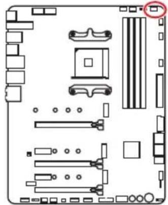
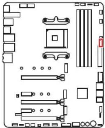
JCORSAIR1: CORSAIR Connector 34
Onboard LEDs 35
EZ Debug LED 35
JPWRLED1: LED power input 35
Debug Code LED 35
Hexadecimal Character Table 36
Boot Phases 36
Debug Code LED Table 36
41
Installing Windows 10 41
41
Installing Utilities 41
BIOS Setup 42
EnteringBIOS Setup 42
ResettingBIOS 43
UpdatingBIOS 43
EZ Mode 45
Advanced Mode 47
OC Menu. 48
Safety Information
-
The components included in this package are prone to damage from electrostatic discharge (ESD). Please adhere to the following instructions to ensure successful computer assembly.
-
Ensure that all components are securely connected. Loose connections may cause the computer to not recognize a component or fail to start.
-
Hold the motherboard by the edges to avoid touching sensitive components.
-
It is recommended to wear an electrostatic discharge (ESD) wrist strap when handling the motherboard to prevent electrostatic damage. If an ESD wrist strap is not available, discharge yourself of static electricity by touching another metal object before handling the motherboard.
-
Store the motherboard in an electrostatic shielding container or on an anti-static pad whenever the motherboard is not installed.
-
Before turning on the computer, ensure that there are no loose screws or metal components on the motherboard or anywhere within the computer case.
-
Do not boot the computer before installation is completed. This could cause permanent damage to the components as well as injury to the user.
-
If you need help during any installation step, please consult a certified computer technician.
-
Always turn off the power supply and unplug the power cord from the power outlet before installing or removing any computer component.
-
Keep this user guide for future reference.
-
Keep this motherboard away from humidity.
-
Make sure that your electrical outlet provides the same voltage as is indicated on the PSU, before connecting the PSU to the electrical outlet.
-
Place the power cord such a way that people can not step on it. Do not place anything over the power cord.
-
All cautions and warnings on the motherboard should be noted.
-
If any of the following situations arises, get the motherboard checked by service personnel:
Liquid has penetrated into the computer.
The motherboard has been exposed to moisture.
-
The motherboard does not work well or you can not get it work according to user guide.
-
The motherboard has been dropped and damaged.
The motherboard has obvious sign of breakage. -
Do not leave this motherboard in an environment above 60^ [140^] , it may damage the motherboard.
Specifications
Continued on next page
| CPU | Supports 2nd and 3rd Gen AMD RyzenTM / RyzenTM with RadeonTM Vega Graphics and 2nd Gen AMD RyzenTM with RadeonTM Graphics Desktop Processors for Socket AM4 |
| Chipset AMD | ® X570 Chipset |
| Memory | • 4x DDR4 memory slots, support up to 128GB* • 3rd Gen AMD RyzenTM Processors support DDR4 1866/2133/2400/2667/2800/2933/3000/3066/3200 MHz by JEDEC, and 2667/2800/2933/3000/3066/3200/3466/3600/3733/3866/4000/4133/4266/4400/4533/4600MHz by A-XMP OC MODE • 2nd Gen AMD RyzenTM Processors, 1st and 2nd Gen AMD RyzenTM with RadeonTM Vega Graphics Processors support DDR4 1866/2133/2400/2667/2800/2933/3000/3066/3200 Mhz by JEDEC, and 2667/2800/2933/3000/3066/3200/3466/3600 MHz by A-XMP OC MODE • Dual channel memory architecture • Supports non-ECC UDIMM memory • Supports ECC UDIMM memory (non-ECC mode) • Supports un-buffered memory * Please refer www.msi.com for more information on compatible memory. |
| Expansion Slots | • 2x PCIe 4.0/3.0 x16 slots (PCI_E1, PCI_E3) • 3rd Gen AMD RyzenTM support PCIe 4.0 x16/x0, x8/x8 modes • 2nd Gen AMD RyzenTM support PCIe 3.0 x16/x0, x8/x8 modes • RyzenTM with RadeonTM Vega Graphics and 2nd Gen AMD RyzenTM with RadeonTM Graphics support PCIe 3.0 x8 mode* • 1x PCIe 4.0/3.0 x16 slot (PCI_E5, supports x4 mode) • 2x PCIe 4.0/3.0 x1 slots** * PCI_E3 slot is only available for 2nd and 3rd Gen AMD RyzenTM processors. ** The PCIe x1 slots can not be used simultaneously. PCI_E2 will be unavailable when installing the PCIe card in PCI_E4 slot. ***The speeds may vary for different devices |
| Multi-GPU | • Supports 2-Way NVIDIA® Technology • Supports 3-Way AMD CrossFire™ Technology |
Continued from previous page
| LAN | 1x Intel® WGI211AT Gigabit LAN controller 1x Realtek® RTL8125 2.5 Gbps LAN controller |
| Wireless LAN & Bluetooth® | Intel® Wi-Fi 6 AX200 • Supports 802.11 a/b/g/n/ac/ax, MU-MINO Rx, 2.4GHz-5GHz [160MHz] up to 2.4Gbps • Supports Bluetooth® • The Wireless module is pre-install in the M2_4 (Key-B slot |
| Audio | Realtek® ALC1220 Codec • 7.1-Channel High Definition Audio • Supports Optical S/PDIF output |
| Storage | AMD® X570 Chipset • 4x SATA 6Gb/s ports • 2x M.2 slots [M2_2/ M2_3, Key M]* • Support PCIe 4.0/ 3.0 x4 and SATA 6Gb/s • Support 2242/ 2260 /2280 storage devices AMD® Processor • 1x M.2 slot [M2_1, Key M]* • Supports PCIe 4.0 x4 (3rd Gen AMD Ryzen™) • Supports PCIe 3.0 x4 (2nd Gen AMD RyzenTM/ RyzenTM with RadeonTM Vega Graphics and 2nd Gen AMD RyzenTM with RadeonTM Graphics) • Supports 2242/ 2260 /2280/ 22110 storage devices *The speeds may vary for different devices |
| RAID | AMD® X570 Chipset • Supports RAID 0, RAID 1 and RAID 10 |
Continued on next page
Continued from previous page
| USB | AMD® X570 Chipset • 3x USB 3.2 Gen2 (SuperSpeed USB 10Gbps) ports (2 Type-A ports on the back panel, 1 Type-C internal connector) • 4x USB 3.2 Gen1 (SuperSpeed USB) ports through the internal USB 3.2 Gen1 connectors • 6x USB 2.0 (High-speed USB) ports (2 Type-A ports on the back panel, 4 ports through the internal USB 2.0 connectors) AMD® Processor • 2x USB 3.2 Gen2 (3rd Gen AMD Ryzen™) or USB 3.2 Gen1 (2nd Gen AMD RyzenTM/ RyzenTM with RadeonTM Vega Graphics and 2nd Gen AMD RyzenTM with RadeonTM Graphics) ports (1x Type-A & 1x Type-C) on the back panel • 2x USB 3.2 Gen1 (SuperSpeed USB) Type-A ports on the back panel |
| I/O Controller NUVOTON | NCT6797 Controller Chip |
| Hardware Monitor | • CPU/ System/Chipset temperature detection • CPU/ System/Chipset fan speed detection • CPU/ System/Chipset fan speed control |
| Form Factor | • ATX Form Factor • 12 in. x 9.6 in. (30.5 cm x 24.4 cm) |
Continued on next page
Continued from previous page
| Internal Connectors | 1x 24-pin ATX main power connector 2x 8-pin ATX 12V power connectors 4x SATA 6Gb/s connectors 2x USB 2.0 connectors (support additional 4 USB 2.0 port 2x USB 3.2 Gen 1 connectors (support additional 4 USB 3 Gen 1 ports) 1x USB 3.2 Gen 2 Type-C Port 1x 4-pin CPU fan connector 5x 4-pin system fan connectors 1x 4-pin water-pump connector 1x Front panel audio connector 2x System panel connectors 1x TPM module connector 1x Clear CMOS jumper 1x Chassis Intrusion connector 1x Power button 1x Reset button 1x Game Boost knob 1x 4-pin RGB LED connector 2x 3-pin RAINBOW LED connectors 1x 3-pin CORSAIR connector 1x 2-pin LED power input 1x Debug Code LED 4x EZ Debug LEDs |
Continued on next page
Continued from previous page
| Back Panel Connectors | • 1x Clear CMOS Button • 1x Flash BIOS Button • 1x WiFi/ Bluetooth module • 1x PS/2 keyboard/ mouse combo port • 2x USB 2.0 ports • 2x USB 3.2 Gen 1 ports • 2x LAN(RJ45) ports • 1x USB 3.2 Gen 2/ 1 Type C port • 1x USB 3.2 Gen 2/ 1 Type A port • 2x USB 3.2 Gen 2 Type A ports • 5x OFC audio jacks • 1x Optical S/PDIF Out connector |
| BIOS Features | • 1x 256 Mb flash • UEFI AMI BIOS • ACPI 6.1, SM BIOS 2.8 • Multi-language |
| Software | • Drivers • DRAGON CENTER • Nahimic Audio • CPU-Z MSI GAMING • MSI App Player (BlueStacks) • Google Chrome™ ,Google Toolbar, Google Drive • Norton™ Internet Security Solution |
| Dragon Center Features | • DRAGON OPTIMIZATION • OC Performance • Hardware Monitor • True Color • LAN Manager • Mystic Light • Live Update Please refer to http://download.msi.com/manual/mb/DRAGONCENTER2.pdf for more details. |
Continued on next page
Continued from previous page
| Special Features | · Audio · Audio Boost HD · Nahimic3 · Voice Boost · Network · GAMING LAN with Gaming LAN Manager · Dual LAN (2.5G+1G) · Intel WiFi · Storage · Lightning Gen 4 M.2 · Triple M.2 · Cooling · Zero Frozr Technology · Frozr Heatsink Design · Propeller Blade technology · M.2 Shield Frozr · Pump Fan · Gaming Fan Control · LED · Mystic Light Infinity · Mystic Light 3 · Mystic Light Extension (RGB) · Mystic Light Extension (RAINBOW) · Mystic Light Extension(CORSAIR) · Mystic light SYNC · EZ DEBUG LED · Protection · DDR4 Steel Armor · PCI-E Steel Armor · Pre-installed IO shielding |
Continued on next page
Continued from previous page
| Special Features | ·Performance ·Lightning Gen 4 PCI-E Slot ·Multi GPU-SLI Technology ·Multi GPU-CrossFire Technology ·DDR4 Boost ·Core Boost ·GAME Boost (8 modes) ·GAME Boost ·OC Engine (Clock gen) ·USB with type A+C ·AMD Turbo USB 3.2 Gen 2 ·Front USB Type-C ·Dual CPU Power ·Gamer Experience ·DRAGON CENTER ·GAMING HOTKEY ·GAMING MOUSE Control ·USB SPEED UP ·Total Fan control ·Live Update ·APP Player ·BIOS ·Click BIOS 5 ·Flash BIOS Button |
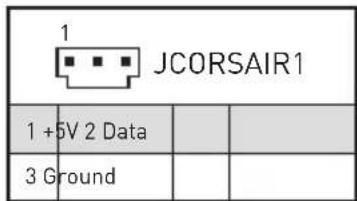
JCORSAIR1 Connector Specification
| Supporting CORSAIR RGB Products Maximum connection | |
| Lighting PRO RGB LED Strip | 20* * 20% brightness is recommended when the number of LED strips exceeds 8. |
| HD120 RGB Fan 6 | |
| SP120 RGB Fan 6 | |
| LL120 RGB Fan 6 | |
Package contents
Please check the contents of your motherboard package. It should contain:
| Motherboard MEG X57 | 0 ACE | |
| Cable | SATA 6Gb/s Cables 4 | |
| 1 to 2 RGB LED Extension Y Cable 80cm 1 | ||
| CORSAIR RGB LED Extension Cable 50cm 1 | ||
| RAINBOW RGB LED Extension Cable 80cm 1 | ||
| Accessories | Antenna Set 1 | |
| 8.5H M.2 screws 3 | ||
| Case Badge 1 | ||
| SATA Cable Labels 1 | ||
| Product Registration Card | 1 | |
| Application DVD | Driver DVD | 1 |
| Documentation | User Manual | 1 |
| Quick Installation Guide | 1 | |
! Important
If any of the above items are damaged or missing, please contact your retailer.
Rear I/O Panel
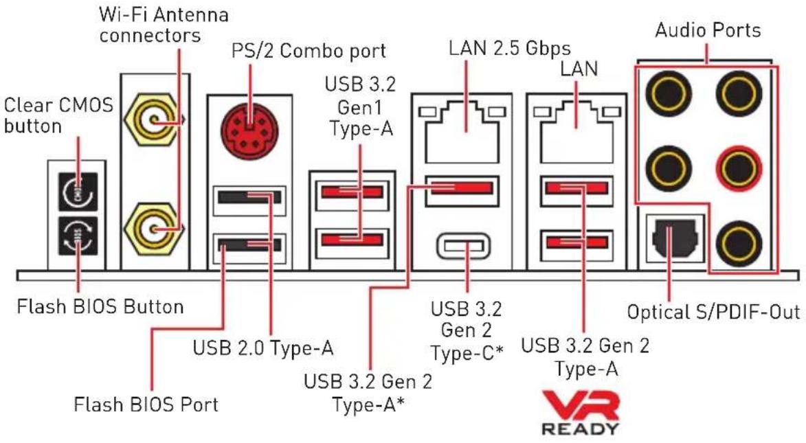
*USB 3.2 Gen2 (3rd Gen AMD Ryzen™) or USB 3.2 Gen1 (2nd Gen AMD Ryzen™/ Ryzen™ with Radeon™ Vega Graphics and 2nd Gen AMD Ryzen™ with Radeon™ Graphics)
- Clear CMOS button - Power off your computer. Press and hold the Clear CMOS button for about 5-10 seconds to reset BIOS to default values.
- Flash BIOS Port/ Button - Please refer to page 44 for Updating BIOS with Flash BIOS Button.
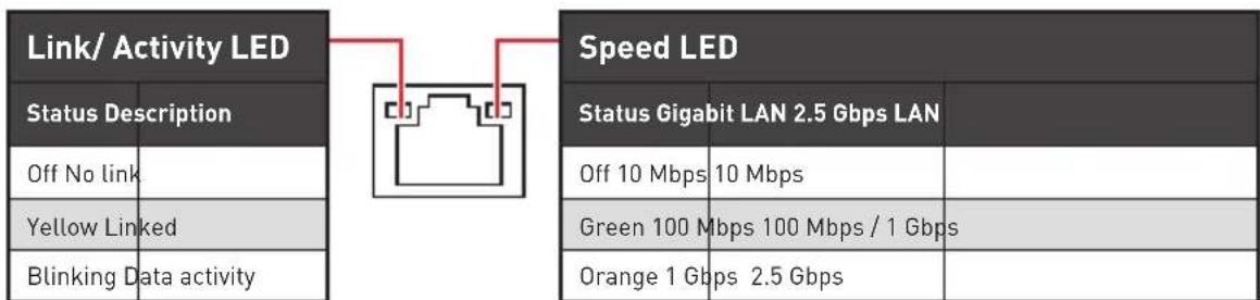
LAN Port LED Status Table
Audio Ports Configuration
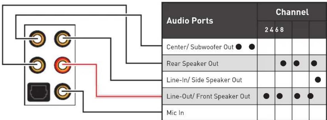
[connected, Blank: empty]
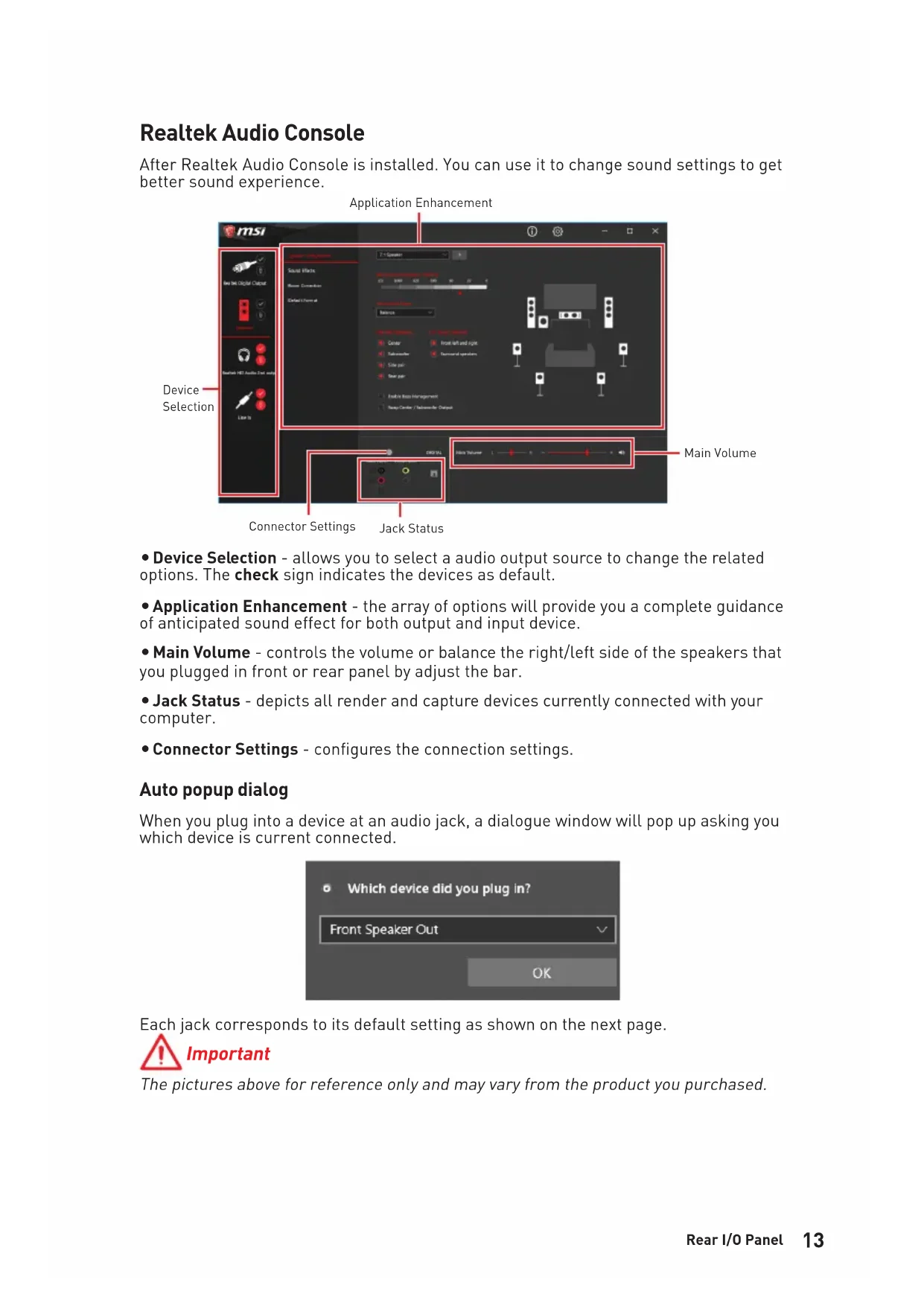
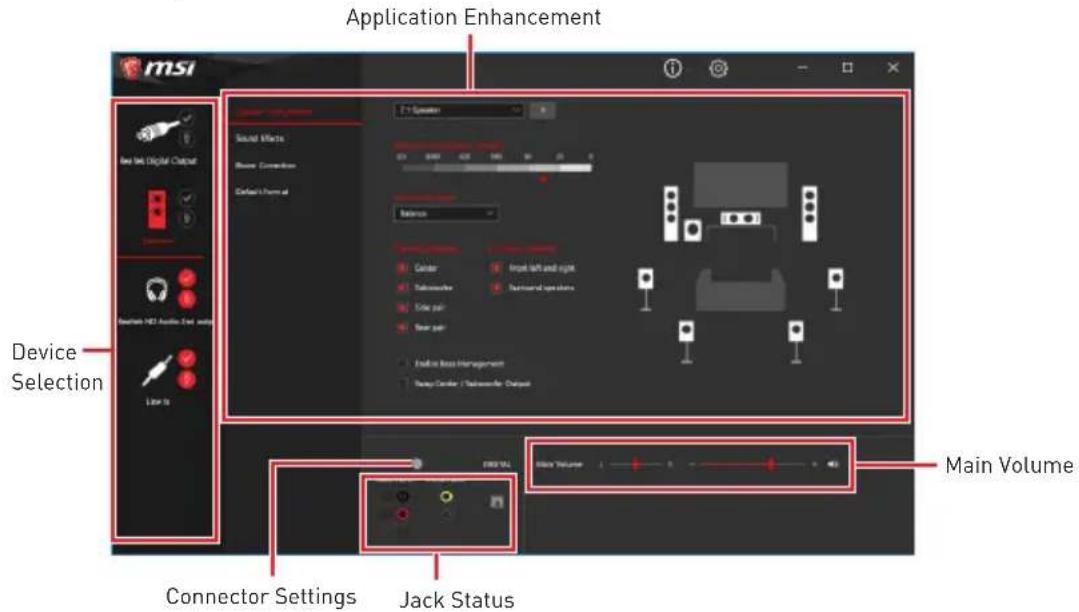
Realtek Audio Console
After Realtek Audio Console is installed. You can use it to change sound settings to get better sound experience.
-
Device Selection - allows you to select a audio output source to change the related options. The check sign indicates the devices as default.
-
Application Enhancement - the array of options will provide you a complete guidance of anticipated sound effect for both output and input device.
-
Main Volume - controls the volume or balance the right/left side of the speakers that you plugged in front or rear panel by adjust the bar.
-
Jack Status - depicts all render and capture devices currently connected with your computer.
-
Connector Settings - configures the connection settings.
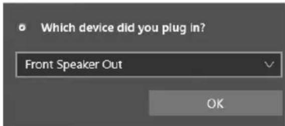
Auto popup dialog
When you plug into a device at an audio jack, a dialogue window will pop up asking you which device is current connected.
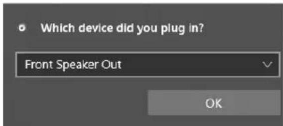
Each jack corresponds to its default setting as shown on the next page.
Important
The pictures above for reference only and may vary from the product you purchased.
Audio jacks to headphone and microphone diagram

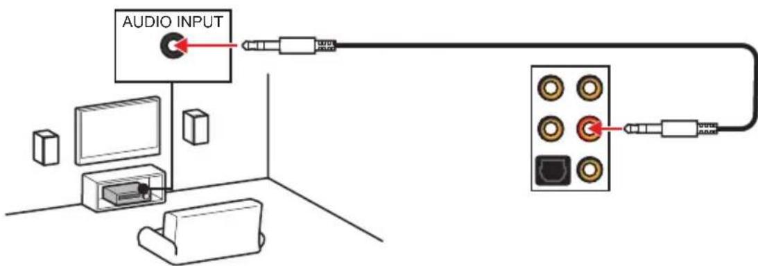
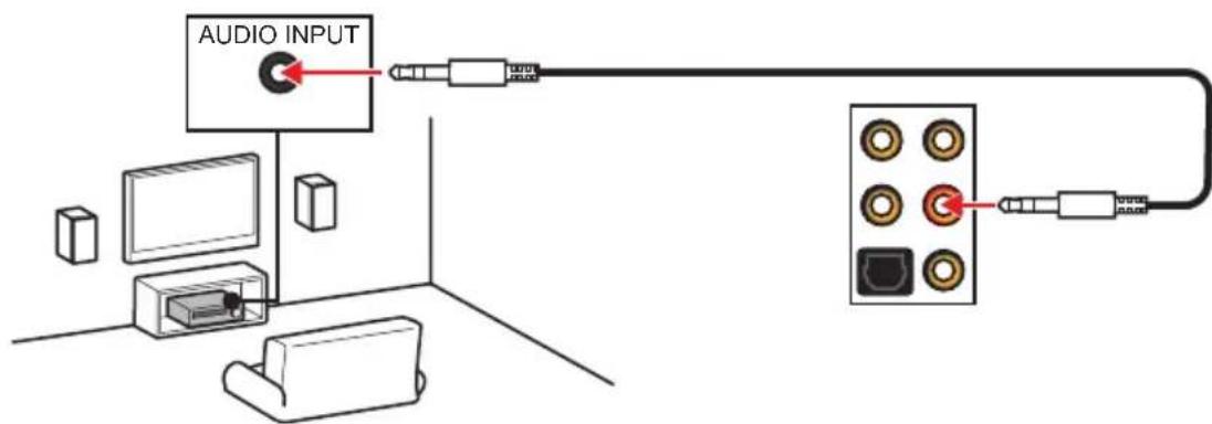
Audio jacks to stereo speakers diagram
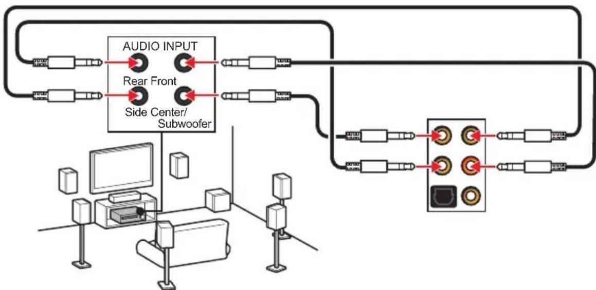
Audio jacks to 7.1-channel speakers diagram
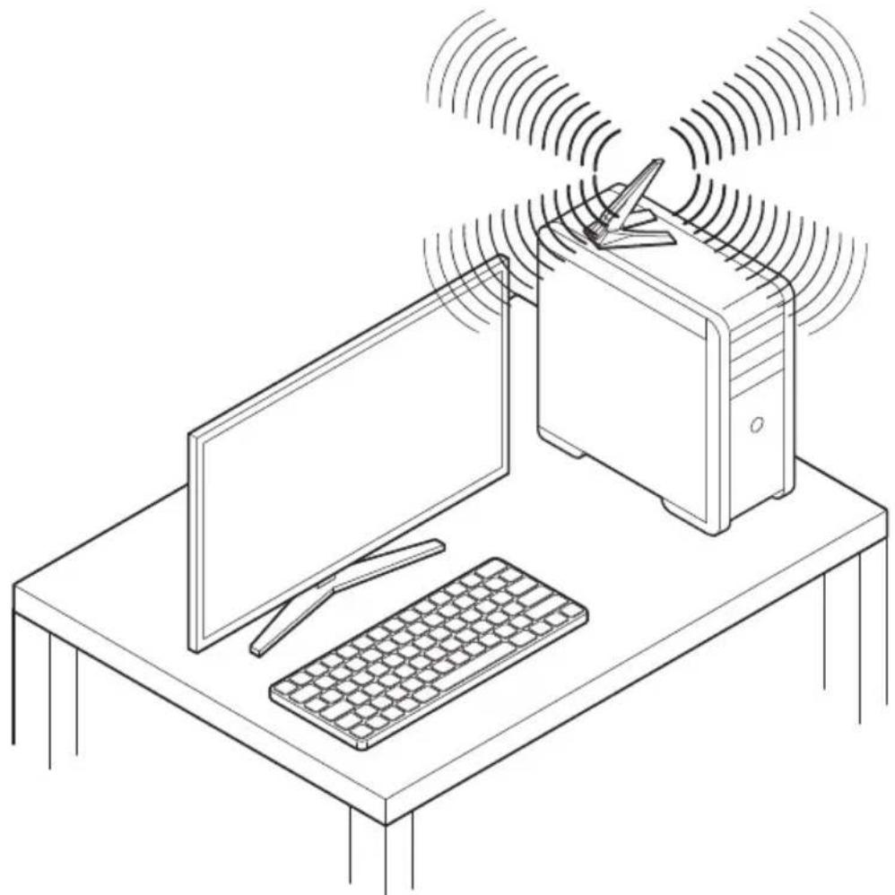
Installing Antennas
- Combine the antenna with the base.
- Screw two antenna cables tight to the WiFi antenna connectors as shown.
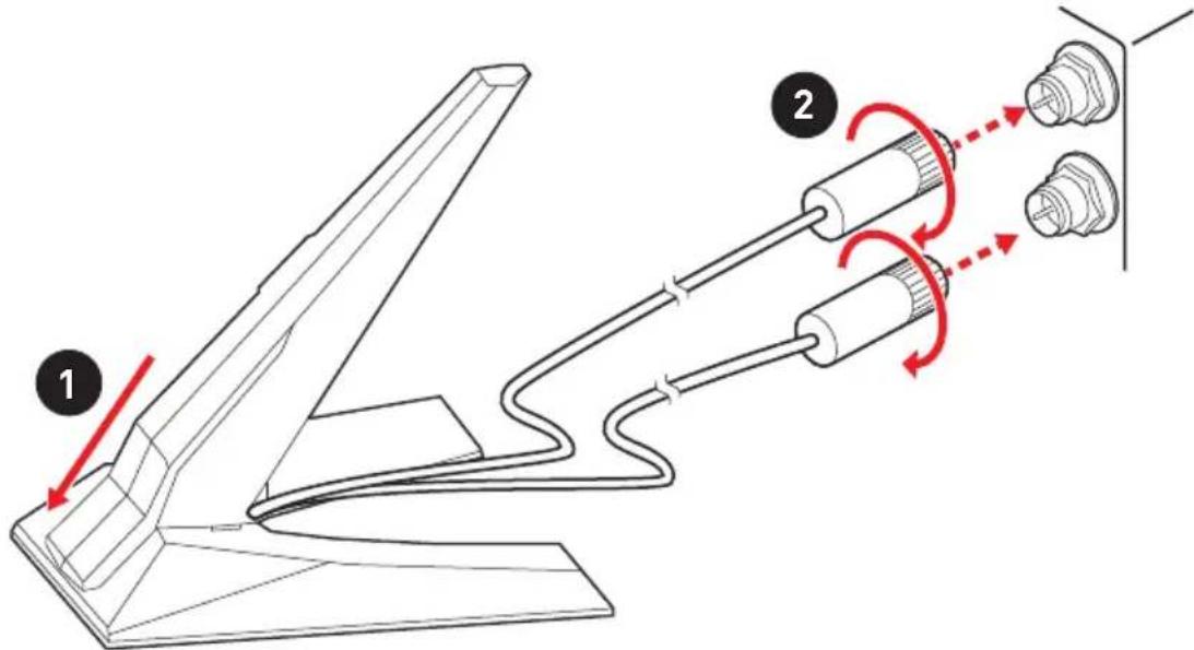
- Place the antenna as high as possible.
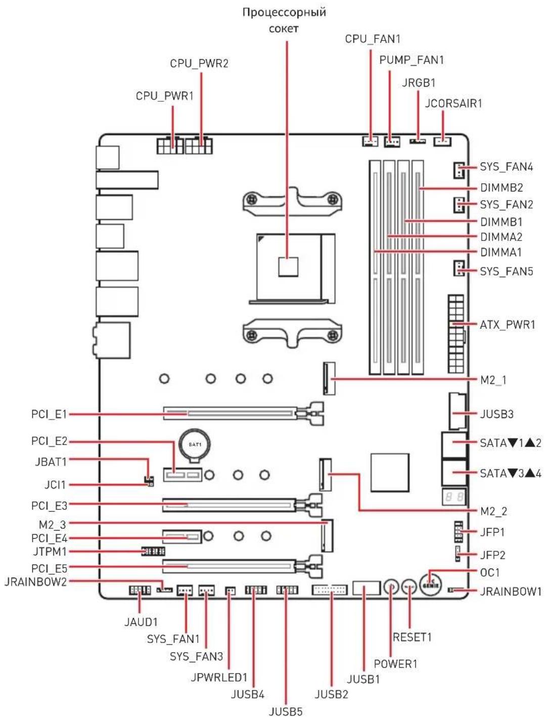
Overview of Components
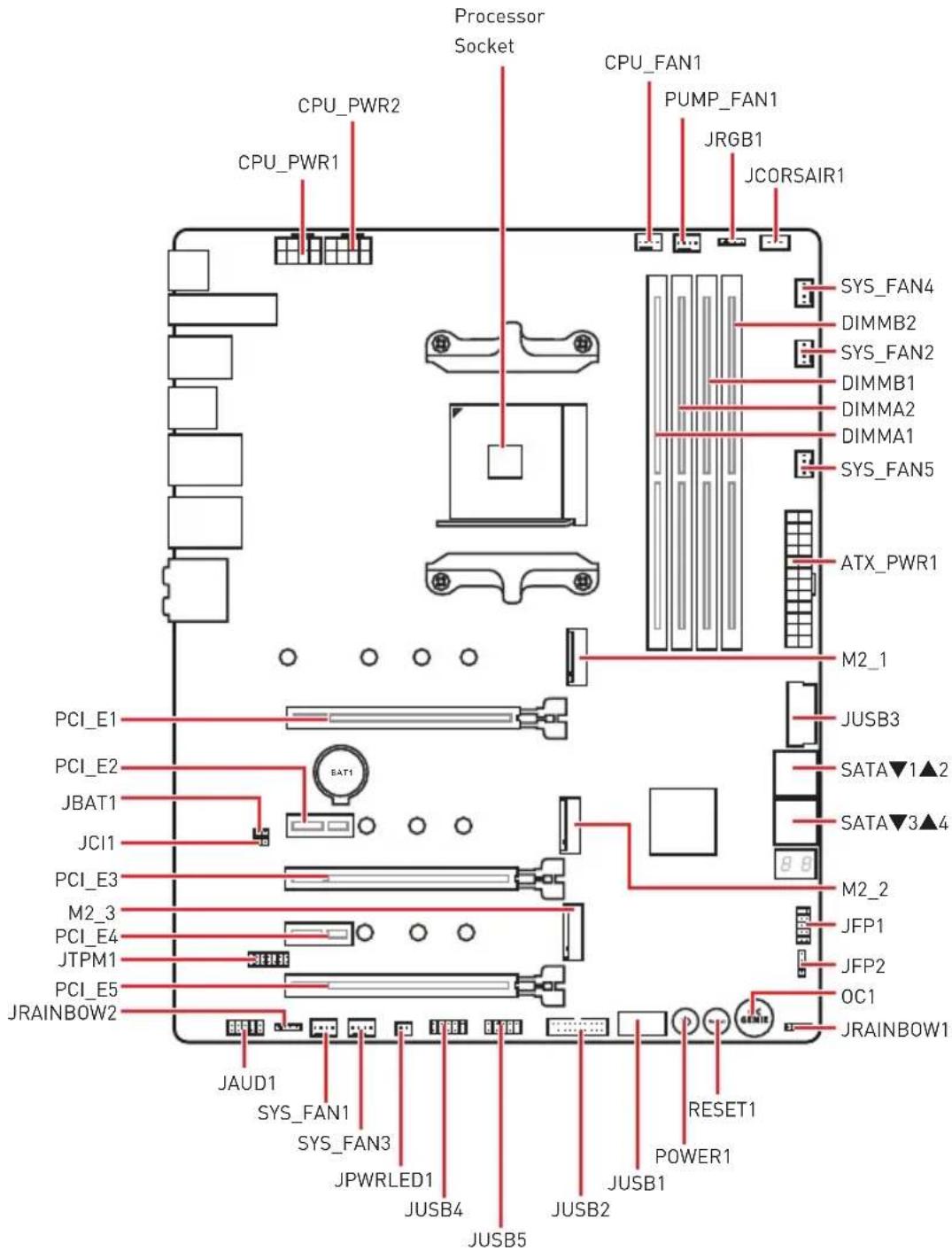
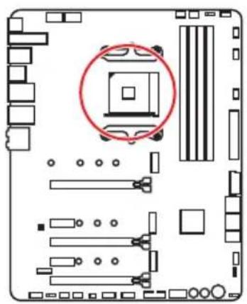
Processor Socket

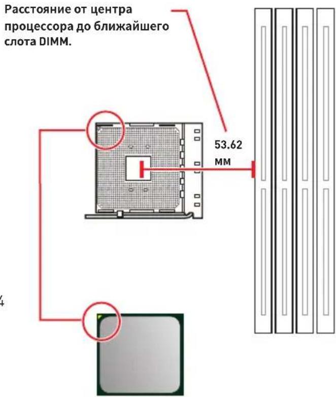
Introduction to the AM4 processor
The surface of the AM4 processor has a yellow triangle to assist in correctly lining up the processor for motherboard placement. The yellow triangle is the Pin 1 indicator.
Important
When changing the processor, the system configuration could be cleared and reset to BIOS to default values, due to the AM4 processor architecture.
Always unplug the power cord from the power outlet before installing or removing the CPU.
When installing a CPU, always remember to install a CPU heatsink. A CPU heatsink is necessary to prevent overheating and maintain system stability.
Confirm that the CPU heatsink has formed a tight seal with the CPU before booting your system.
Overheating can seriously damage the CPU and motherboard. Always make sure the cooling fans work properly to protect the CPU from overheating. Be sure to apply an even layer of thermal paste (or thermal tape) between the CPU and the heatsink to enhance heat dissipation.
If you purchased a separate CPU and heatsink/ cooler, Please refer to the documentation in the heatsink/ cooler package for more details about installation.
This motherboard is designed to support overclocking. Before attempting to overclock, please make sure that all other system components can tolerate overclocking. Any attempt to operate beyond product specifications is not recommended. MSI® does not guarantee the damages or risks caused by inadequate operation beyond product specifications.
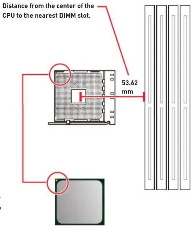
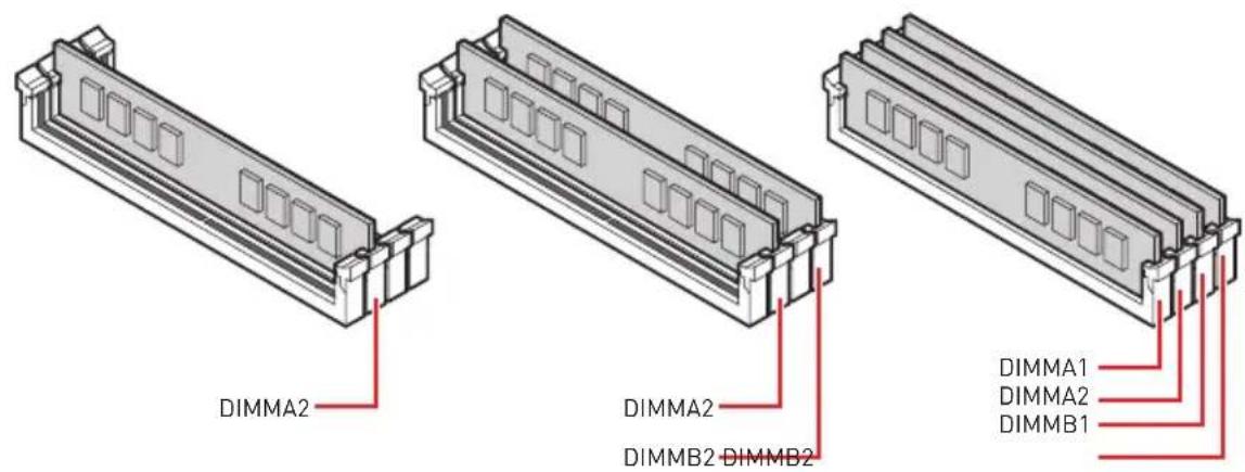
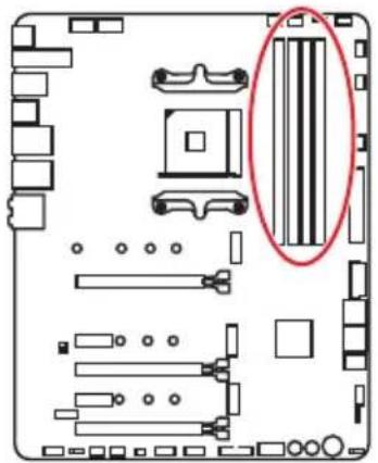
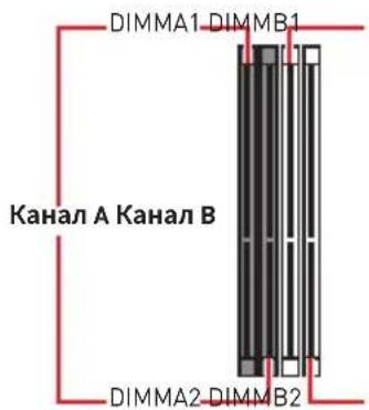
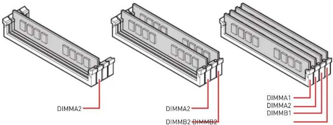
DIMM Slots

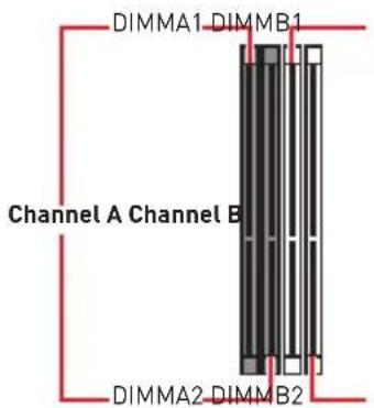

Memory module installation recommendation

Important
Always insert memory modules in the DIMMA2 slot first.
Due to chipset resource usage, the available capacity of memory will be a little less than the amount of installed.
Based on processor specification, the Memory DIMM voltage below 1.35V is suggested to protect the processor.
Some memory modules may operate at a lower frequency than the marked value when overlapping due to the memory frequency operates dependent on its Serial Presence Detect (SPD). Go to BIOS and find the DRAM Frequency! to set the memory frequency if you want to operate the memory at the marked or at a higher frequency.
It is recommended to use a more efficient memory cooling system for full DIMMs installation or overclocking.
The stability and compatibility of installed memory module depend on installed CPU and devices when overclocking.
Due to AM4 processor/ memory controller official specification limitation, the frequency of memory modules may operate lower than the marked value under the default state. Please refer www.msi.com for more information on compatible memory.
PCI_E1~5: PCIe Expansion Slots
| Slots | 3rd Gen AMD Ryzen™ | 2nd Gen AMD Ryzen™ | Ryzen™ with Radeon™ Vega Graphics and 2nd Gen AMD Ryzen™ with Radeon™ Graphics |
| PCI_E1 | PCIe 4.0 x16 | PCIe 3.0 x16 | PCIe 3.0 x8 |
| PCI_E2 | PCIe 4.0 x1 | PCIe 3.0 x1 | PCIe 3.0 x1 |
| PCI_E3 | PCIe 4.0 x8 | PCIe 3.0 x8 | Unavailable |
| PCI_E4 | PCIe 4.0 x1 | PCIe 3.0 x1 | PCIe 3.0 x1 |
| PCI_E5 | PCIe 4.0 x4 | PCIe 3.0 x4 | PCIe 3.0 x4 |

Important
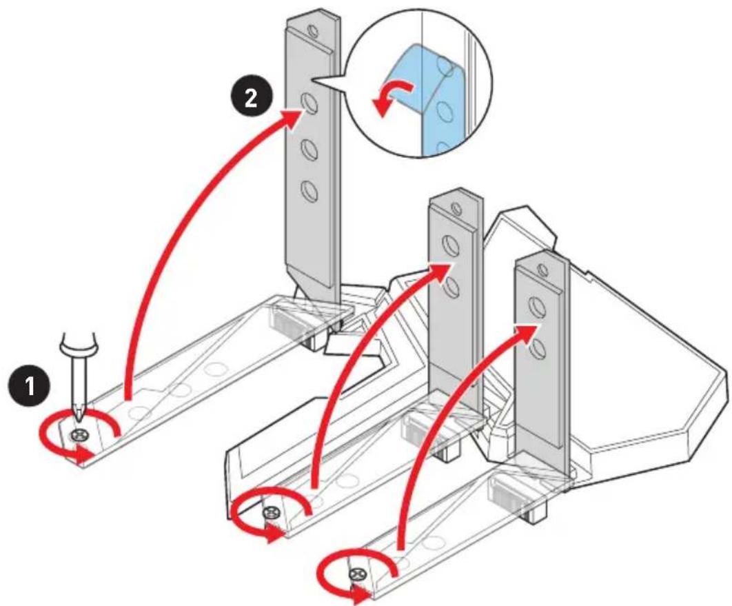
If you install a large and heavy graphics card, you need to use a tool such as MSI Gaming Series Graphics Card Bolster to support its weight to prevent deformation of the slot.
For a single PCIe x16 expansion card installation with optimum performance, using the PCI_E1 slot is recommended.
When adding or removing expansion cards, always turn off the power supply and unplug the power supply power cable from the power outlet. Read the expansion card's documentation to check for any necessary additional hardware or software changes.
The PCIe x1 slots can not be used simultaneously. PCI_E2 will be unavailable when installing the PCIe card in PCI_E4 slot.
PCIe bandwidth table
Please refer the table below to install the PCIe devices.
For 3rd Gen AMD RyzenTM
| Slot Single 2-Way 3-Way* | ||||||
| PCI_E1 (CPU) | @4.0 x16 @4.0 x8 @4.0 x8 | |||||
| PCI_E2 (PCH) | 4.0 x1 - 4.0 x1 - 4.0 x1 - | |||||
| PCI_E3 (CPU) | — @4.0 x8 @4.0 x8 | |||||
| PCI_E4 (PCH) | — 4.0 x1 — 4.0 x1 — | 4.0 x1 | ||||
| PCI_E5 (PCH) | 4.0 x4 | 4.0 x4 | @4.0 x4 | |||
: unavailable, @: graphics card, *: CrossFire only
For 2nd Gen AMD RyzenTM
| Slot Single 2-Way 3-Way* | ||||||
| PCI_E1 (CPU) | @3.0 x16 @3.0 x8 @3.0 x8 | |||||
| PCI_E2 (PCH) | 3.0 x1 - 3.0 x1 - 3.0 x1 - | |||||
| PCI_E3 (CPU) | — @3.0 x8 @3.0 x8 | |||||
| PCI_E4 (PCH) | — 3.0 x1 — 3.0 x1 — | 3.0 x1 | ||||
| PCI_E5 (PCH) | 3.0 x4 3.0 x4 @3.0 x4 | |||||
(available, @: graphics card, *: CrossFire only)
For Ryzen™ with Radeon™ Vega Graphics and 2nd Gen AMD Ryzen™ with Radeon™ Graphics
| Slot Single | 2-Way* | |||
| PCI_E1 (CPU) | @3.0 x8 | @3.0 x8 | ||
| PCI_E2 (PCH) | 3.0 x1 | — | 3.0 x1 | — |
| PCI_E3 (CPU) | — | — | ||
| PCI_E4 (PCH) | — | 3.0 x1 | — | 3.0 x1 |
| PCI_E5 (PCH) | 3.0 x4 | @3.0 x4 | ||
(—: unavailable, @: graphics card, *: CrossFire only)
M2_1~3: M.2 Slots (Key M)
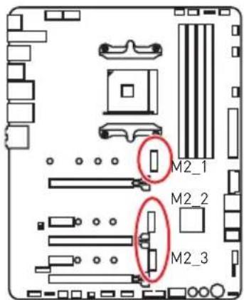
The following table describes the relationship between the M.2 slots and the PCIe bandwidth of the processors.
| Slots | 3rd Gen AMD RyzenTM | 2nd Gen AMD RyzenTM | RyzenTM with RadeonTM Vega Graphics and 2nd Gen AMD RyzenTM with RadeonTM Graphics |
| M2_1 PCIe 4.0 x4 PCIe 3.0 x4 PCIe 3.0 x4 | |||
| M2_2 PCIe 4.0 x4 PCIe 3.0 x4 PCIe 3.0 x4 | |||
| M2_3 PCIe 4.0 x4 PCIe 3.0 x4 PCIe 3.0 x4 |
Installing M.2 module
- Loosen the screws of M.2 SHIELD FROZR heatsink.
- Lift the M.2 SHIELD FROZR heatsink and remove the protective films from the thermal pads.
- Move and fasten the M.2 standoff to the appropriate position for your M.2 SSD. Please make sure there is no M.2 standoff underneath the M.2 SSD to avoid damage to it.


- Insert your M.2 SSDs into the M.2 slots at a 30-degree angle.
- If the M.2 SSD is shorter than the M.2 SHIELD FROZR heatsink, please secure the M.2 SSD in place with 8.5H M.2 screw. If the length of M.2 SSD equals the M.2 SHIELD FROZR heatsink, please skip this step.
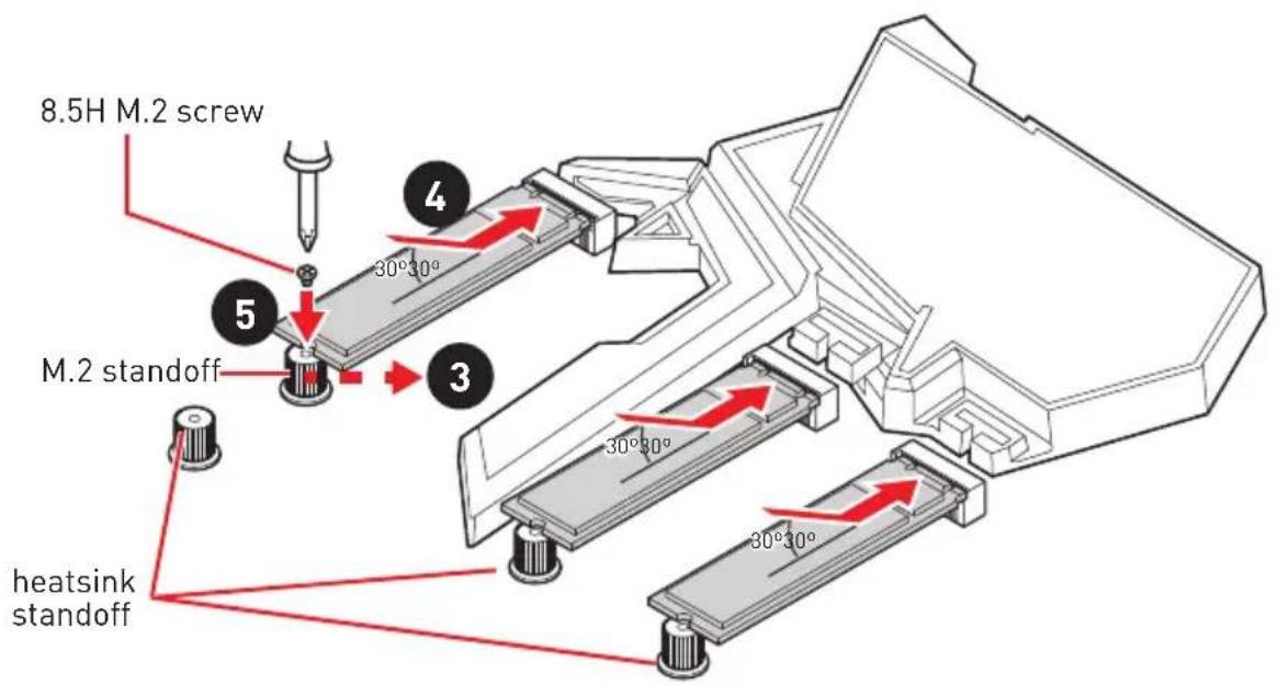
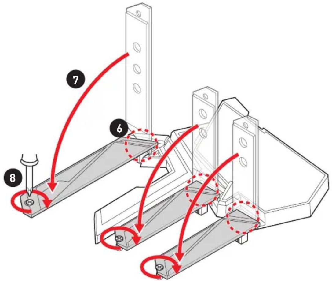
- Insert the M.2 SHIELD FROZR heatsink shaft into the groove.
- Push the M.2 SHIELD FROZR heatsink down.
- Secure the M.2 SHIELD FROZR heatsink to the heatsink standoff.
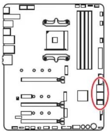
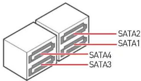
SATA1~4: SATA 6Gb/s Connectors
These connectors are SATA 6Gb/s interface ports. Each connector can connect to one SATA device.
Important
Please do not fold the SATA cable at a 90-degree angle. Data loss may result during transmission otherwise.
SATA cables have identical plugs on either sides of the cable. However, it is recommended that the flat connector be connected to the motherboard for space saving purposes.
JFP1, JFP2: Front Panel Connectors
These connectors connect to the switches and LEDs on the front panel.
| JFP1 | Power Switch | - | + | Reserved |
| + | - | Reset Switch | ||
| Power LED | - | - | - | |
| + | - | HDD LED | ||
| 2 | 1 | |||
| 1 | DD LED + 2 Power LED + | |||
| 3 | HDD LED - | 4 | Power LED - | |
| 5 | Reset Switch | 6 | Power Switch | |
| 7 | Reset Switch | 8 | Power Switch | |
| 9 | Reserved | 10 | No Pin |
| JFP2 | 1 S | Speaker - 2 Buzzer + | ||
| 3 B | Buzzer - 4 Speaker + |
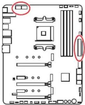
CPU_PWR1~2,ATX_PWR1:Power Connectors
These connectors allow you to connect an ATX power supply.
| CPU_PWR1~2 | |||
| 1 Ground 5 | +12V | ||
| 2 Ground 6 | +12V | ||
| 3 Ground 7 | +12V | ||
| 4 Ground 8 | +12V | ||
| 12 24 13 ATX_PWR1 | 1 +3.3V 13 +3.3V | ||
| 2 +3.3V 14 -12V | |||
| 3 Ground 15 Ground | |||
| 4 +5V 16 PS-ON# | |||
| 5 Ground 17 Ground | |||
| 6 +5V 18 Ground | |||
| 7 Ground 19 Ground | |||
| 8 PWR OK 20 Res | |||
| 9 5V SB 21 +5V | |||
| 10 +12V 22 +5V | |||
| 11 +12V 23 +5V | |||
| 12 +3.3V 24 Ground |

Important
Make sure that all the power cables are securely connected to a proper ATX power supply to ensure stable operation of the motherboard.
OC1: GAME BOOST Knob
This knob allows you to manually select a stage from number 0 (default) to number 11 (extreme) for overclocking the processor. The processor's voltage and frequency will be automatically adjusted after you power on your computer. This function will only be available if the installed processor supports this function.

Using GAME BOOST Knob
To setup the GAME BOOST knob, take the following steps:
- Set the GAME BOOST knob to hardware mode in BIOS Setup.
- Power off the computer.
- Rotate the GAME BOOST knob to select the overclocking stage as you desire.
| Stage | CPU Frequency (GHz) | |||||
| Ryzen 7 Ryzen 5 Ryzen 3 | ||||||
| 2700X 2700 2600X 2600 2400G 2200G | ||||||
| 0 | 3.7 | 3.2 | 3.6 | 3.4 | 3.6 | 3.2 |
| 1 | 4.1 | 3.6 | 4 | 3.8 | 3.8 | 3.6 |
| 2 | 4.15 | 3.65 | 4.05 | 3.85 | 3.85 | 3.65 |
| 4 | 4.2 | 3.7 | 4.1 | 3.9 | 3.9 | 3.7 |
| 6 | 4.25 | 3.75 | 4.15 | 3.95 | 3.95 | 3.75 |
| 8 | 4.3 | 3.8 | 4.2 | 4 | 4 | 3.8 |
| 10 | 4.35 | 3.85 | 4.25 | 4.05 | 4.05 | 3.85 |
| 11 | 4.4 | 3.9 | 4.3 | 4.1 | 4.1 | 3.9 |
- Power on and then GAME BOOST will automatically overclock processor depending on the stage you selected.
To disable GAME BOOST:
- Set the GAME BOOST knob to HW mode in BIOS Setup.
- Power off the computer.
- Rotate the GAME BOOST knob to 0 and then power on. The configuration parameters will be returned to default values.
! Important
You can also control the GAME BOOST function in BIOS Setup or with MSI DRAGON CENTER software.
In order to optimize performance and improve system stability, when you activate the GAME BOOST function, please leave the settings in the BIOS > OC menu unchanged.
The success of overclocking depends on the components of your computer.
We do not guarantee the GAME BOOST overclocking range or the damages/risks caused by overclocking behavior.
MSI components are recommended for better compatibility when using GAME BOOST function.
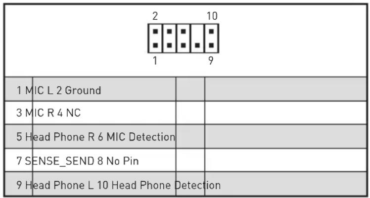
JAUD1: Front Audio Connector
This connector allows you to connect audio jacks on the front panel.
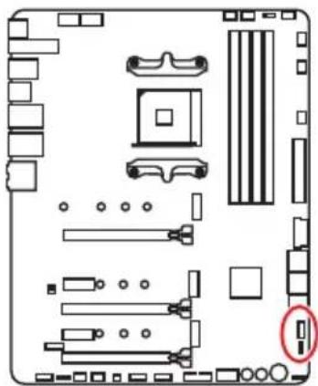
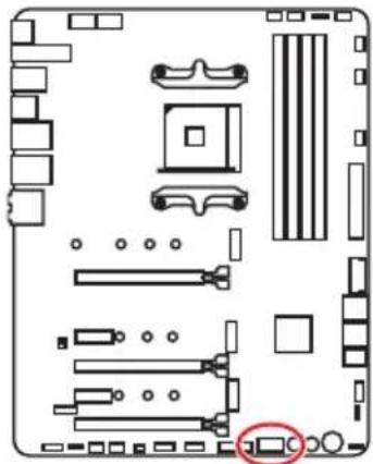
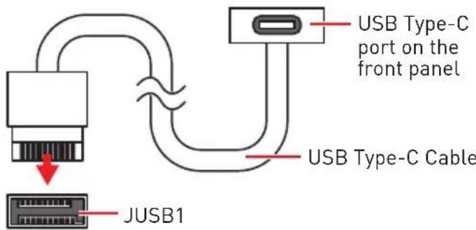
JUSB1: USB 3.2 Gen 2 Type-C Connector
This connector allows you to connect USB 3.2 Gen 2 Type-C connector on the front panel. The connector possesses a foolproof design. When you connect the cable, be sure to connect it with the corresponding orientation.
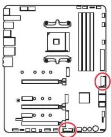
JUSB2~3: USB 3.2 Gen1 Connector
These connectors allow you to connect USB 3.2 Gen1 ports on the front panel.
| 10 1 JUSB3 1 20 | 1 10 JUSB2 | ||
| 1 Power 11 USB2.0+ | |||
| 2 USB3_RX_DN 12 USB2.0- | |||
| 3 USB3_RX_DP 13 Ground | |||
| 4 Ground 14 | USB3_TX_C_DP | ||
| 5 | USB3_TX_C_DN | 15 | USB3_TX_C_DN |
| 6 | USB3_TX_C_DP | 16 | Ground |
| 7 Ground 17 | USB3_RX_DP | ||
| 8 | USB2.0- | 18 | USB3_RX_DN |
| 9 | USB2.0+ | 19 | Power |
| 10 | NC | 20 | No Pin |
Important
Note that the Power and Ground pins must be connected correctly to avoid possible damage.
JUSB4~5: USB 2.0 Connectors
These connectors allow you to connect USB 2.0 ports on the front panel.
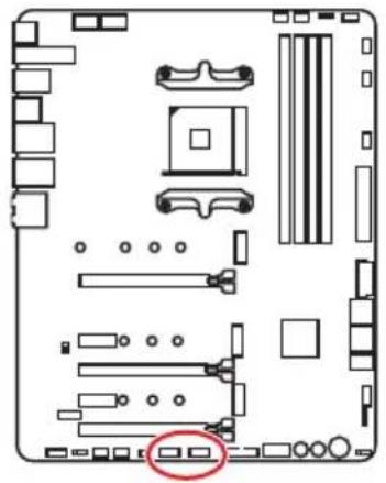
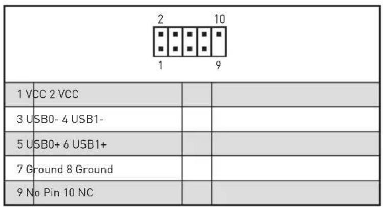
! Important
Note that the VCC and Ground pins must be connected correctly to avoid possible damage.
In order to recharge your iPad,iPhone and iPod through USB ports, please install MSI® DRAGON CENTER utility.
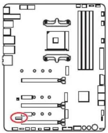
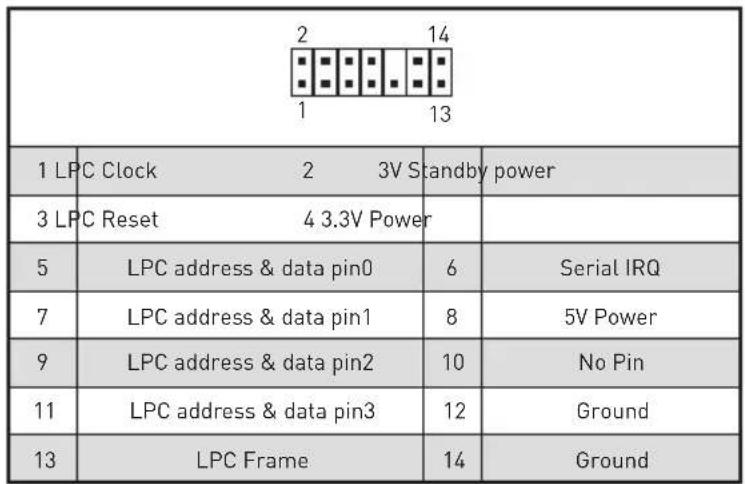
JTPM1: TPM Module Connector
This connector is for TPM (Trusted Platform Module). Please refer to the TPM security platform manual for more details and usages.
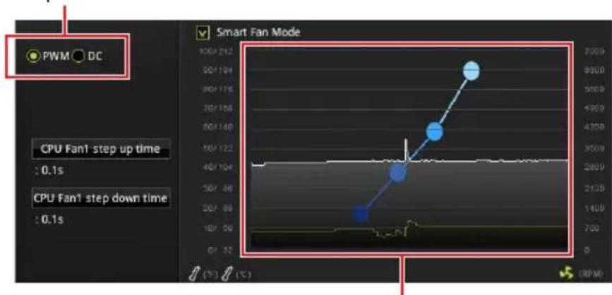
CPU_FAN1, PUMP_FAN1, SYS_FAN1~5: Fan Connectors
Fan connectors can be classified as PWM (Pulse Width Modulation) Mode or DC Mode. PWM Mode fan connectors provide constant 12V output and adjust fan speed with speed control signal. DC Mode fan connectors control fan speed by changing voltage. You can follow the instruction below to adjust the fan connector to PWM or DC Mode.
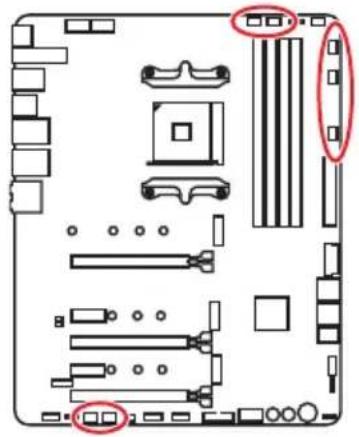
Default PWM Mode fan connectors

CPU_FAN1/PUMP_FAN1
Default DC Mode fan connectors

SYS_FAN1&3

SYS_FAN2,4&5
You can switch between PWM mode and DC mode and adjust fan speed in BIOS > HARDWARE MONITOR.
Select PWM mode or DC mode
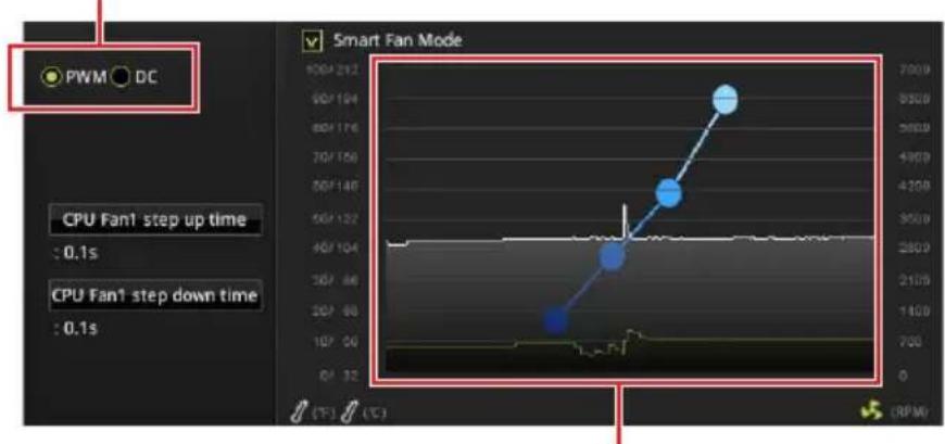
There are gradient points of the fan speed that allow you to adjust fan speed in relation to CPU temperature.
Important
Make sure fans are working properly after switching the PWM/ DC mode.
Pin definition of fan connectors
| PWM Mode pin definition | |||
| 1 G | round 2 +12V | ||
| 3 S | sense 4 Speed Control | Signal | |
| DC Mode pin definition | |||
| 1 G | Ground 2 Voltage | Control | |
| 3 S | Sense 4 NC | ||
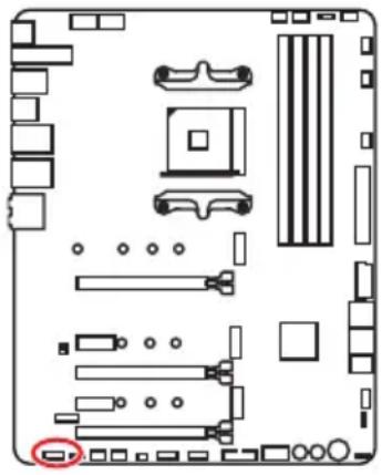
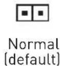
JCI1: Chassis Intrusion Connector
This connector allows you to connect the chassis intrusion switch cable.
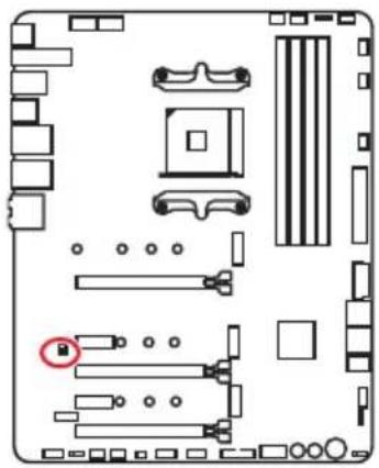

Using chassis intrusion detector
- Connect the JCI1 connector to the chassis intrusion switch/ sensor on the chassis.
- Close the chassis cover.
- Go to BIOS > SETTINGS > Security > Chassis Intrusion Configuration.
- Set Chassis Intrusion to Enabled.
- Press F10 to save and exit and then press the Enter key to select Yes.
- Once the chassis cover is opened again, a warning message will be displayed on screen when the computer is turned on.
Resetting the chassis intrusion warning
- Go to BIOS > SETTINGS > Security > Chassis Intrusion Configuration.
- Set Chassis Intrusion to Reset.
- Press F10 to save and exit and then press the Enter key to select Yes.
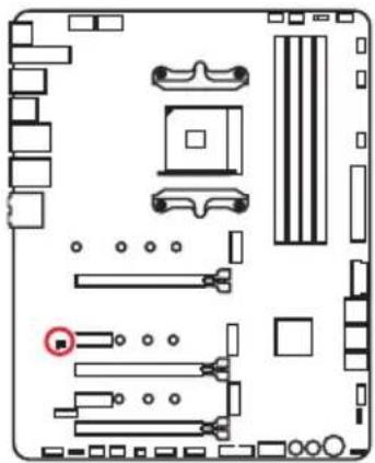
JBAT1: Clear CMOS (Reset BIOS) Jumper
There is CMOS memory onboard that is external powered from a battery located on the motherboard to save system configuration data. If you want to clear the system configuration, set the jumpers to clear the CMOS memory.
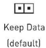
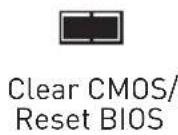
Resetting BIOS to default values
- Power off the computer and unplug the power cord.
- Use a jumper cap to short JBAT1 for about 5-10 seconds.
- Remove the jumper cap from JBAT1.
- Plug the power cord and Power on the computer.
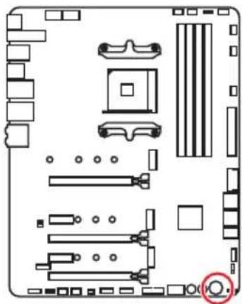
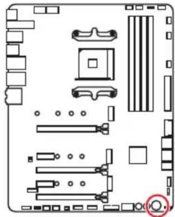
POWER1, RESET1: Power Button, Reset Button
The Power / Reset button allows you to power on / reset the computer.
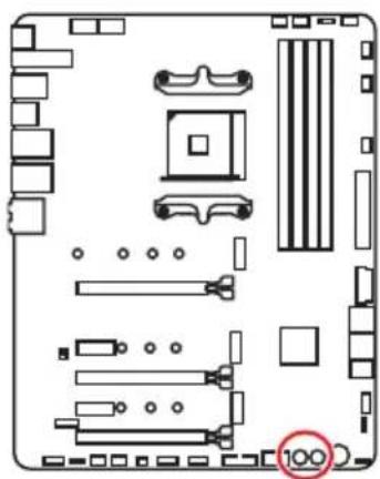


Power button
Reset button
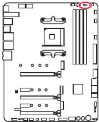
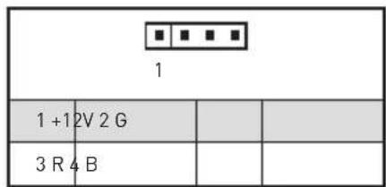
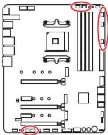
JRGB1: RGB LED connector
The JRGB connector allows you to connect the 5050 RGB LED strips 12V.
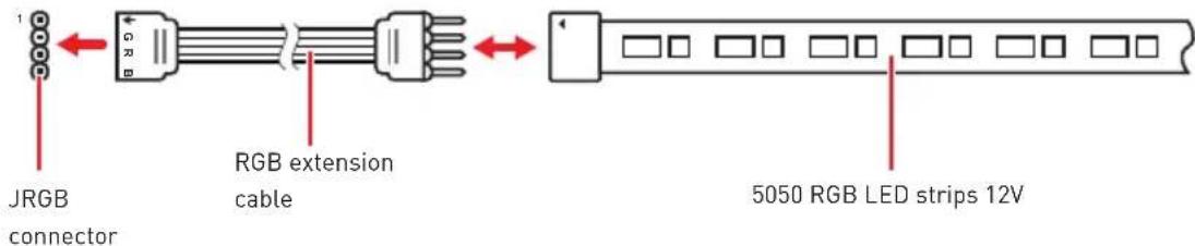
RGB LED Strip Connection
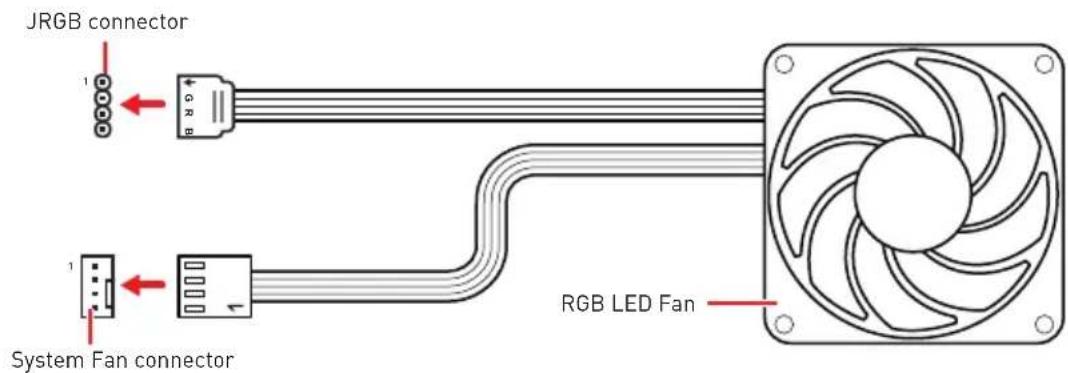
RGB LED Fan Connection
Important
The JRGB connector supports up to 2 meters continuous 5050 RGB LED strips (12V/G/R/B) with the maximum power rating of 3A (12V).
Always turn off the power supply and unplug the power cord from the power outlet before installing or removing the RGB LED strip.
Please use MSI's software to control the extended LED strip.
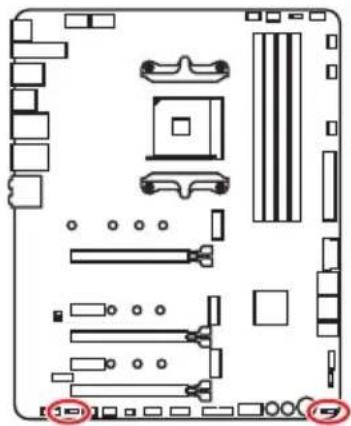
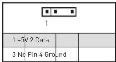
JRAINBOW1~2: Addressable RGB LED connectors
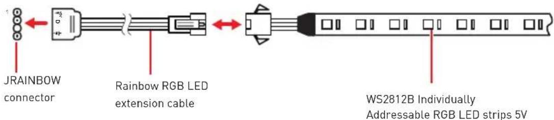
The JRAINBOW connectors allow you to connect the WS2812B Individually Addressable RGB LED strips 5V.
Addressable RGB LED Strip Connection
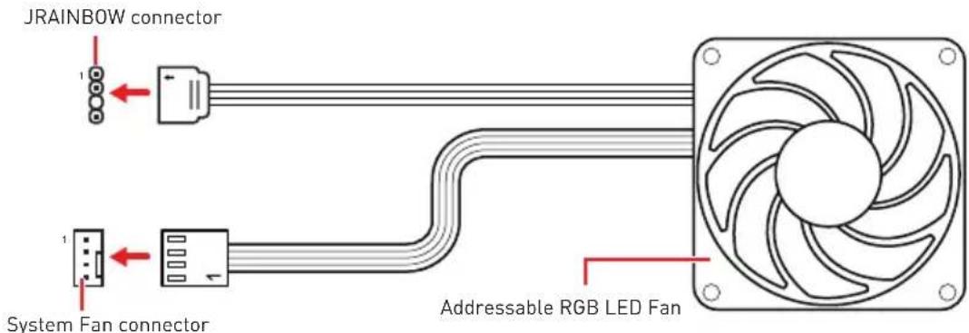
Addressable RGB LED Fan Connection

CAUTION
Do not connect the wrong type of LED strips. The JRGB connector and the JRAINBOW connector provide different voltages, and connecting the 5V LED strip to the JRGB connector will result in damage to the LED strip.

Important
The JRAINBOW connector supports up to 75 LEDs WS2812B Individually Addressable RGB LED strips (5V/Data/Ground) with the maximum power rating of 3A (5V). In the case of 20% brightness, the connector supports up to 200 LEDs.
Always turn off the power supply and unplug the power cord from the power outlet before installing or removing the RGB LED strip.
Please use MSI's software to control the extended LED strip.
JCORSAIR1: CORSAIR Connector
The JCORSAIR1 connector allows you to connect the CORSAIR Individually Addressable Lighting PRO RGB LED strips 5V or CORSAIR RGB fans with the CORSAIR fan hub. Once all items are connected properly, you can control the CORSAIR RGB LED strips and fans with MSI's software.
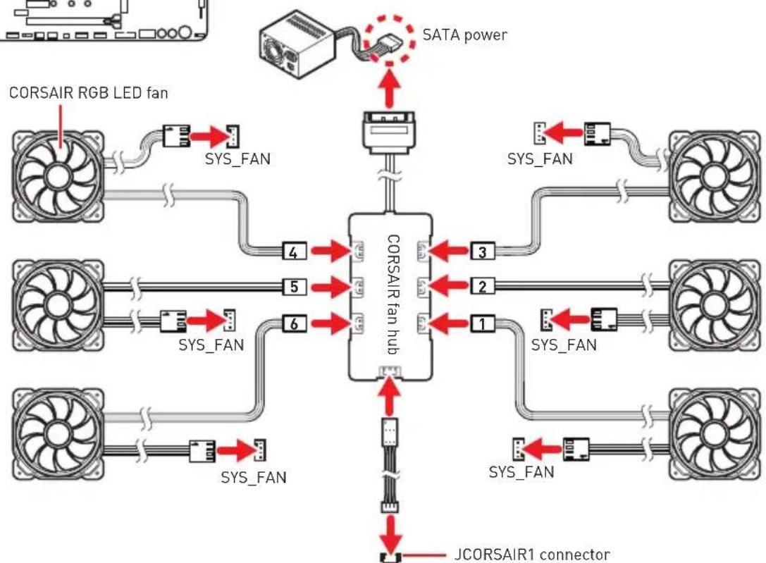
CORSAIR RGB Fan Connection
CORSAIR Lighting Node PRO Connection

JCORSAIR1 connector
Important
Fans must start at 1 and continue in series. 1 > 2 > 3 > 4 > 5 > 6 . Any fan not connected in series will break communication and the RGB LED lighting function will not work.
Quantity of RGB LED Fans or RGB LED Lighting PRO strips supported may differ between models. Please refer to the motherboard specification.
CORSAIR RGB LED Fan and CORSAIR Lighting Node PRO can't be used at the same time.
Onboard LEDs
EZ Debug LED
These LEDs indicate the debug status of the motherboard.
- CPU - indicates CPU is not detected or fail.
DRAM - indicates DRAM is not detected or fail.
VGA - indicates GPU is not detected or fail. - BOOT - indicates the booting device is not detected or fail.
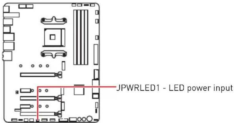
JPWRLED1: LED power input
This connector is used by retailers to demonstrate onboard LED lights.
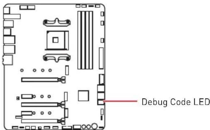
Debug Code LED
The Debug Code LED displays progress and error codes during and after POST. Refer to the Debug Code LED table for details.
Hexadecimal Character Table
| Hexadecimal 0 | 1 2 | 3 4 5 | 6 7 | 8 9 A | B C | D E | F | ||||||||
| Debug Code LED display | 0 | 123456789ABCDEF | |||||||||||||
Boot Phases
Security (SEC) - initial low-level initialization
Pre-EFI Initialization (PEI) - memory initialization
Driver Execution Environment (DXE) - main hardware initialization
Boot Device Selection (BDS) - system setup, pre-OS user interface & selecting a bootable device (CD/DVD, HDD, USB, Network, Shell, ...)
Debug Code LED Table
SEC Progress Codes
| 01 Power on. Reset type detection (soft/hard) |
| 02 AP initialization before microcode loading |
| 03 System Agent initialization before microcode loading |
| 04 PCH initialization before microcode loading |
| 06 Microcode loading |
| 07 AP Initialization after microcode loading |
| 08 System Agent initialization after microcode loading |
| 09 PCH initialization after microcode loading |
| 0B Cache initialization |
SEC Error Codes
| OC - OD R | Reserved for future AMI SEC error codes |
| OE Microcode not found | |
| OF Microcode not loaded | |
PEI Progress Codes
| 10 PEI | Core is started |
| 11 Pre | -memory CPU initialization is started |
| 12 - 14 Pre | e-memory CPU initialization (CPU module specific) |
| 15 Pre | -memory System Agent initialization is started |
| 16 - 18 Pre | e-Memory System Agent initialization (System Agent module specific) |
| 19 Pre | -memory PCH initialization is started |
| 1A - 1C Pre | pre-memory PCH initialization (PCH module specific) |
| 2B Me | Memory initialization. Serial Presence Detect (SPD) data reading |
| 2C Mem | Memory initialization. Memory presence detection |
| 2D Mem | Memory initialization. Programming memory timing information |
| 2E Mem | Memory initialization. Configuring memory |
| 2F Mem | Memory initialization (other) |
| 31 Mem | Installed |
| 32 CPU | post-memory initialization is started |
| 33 CPU | post-memory initialization. Cache initialization |
| 34 CPU | post-memory initialization. Application Processor(s) (AP) initialization |
| 35 CPU | post-memory initialization. Boot Strap Processor (BSP) selection |
| 36 CPU | post-memory initialization. System Management Mode (SMM) initialization |
| 37 Post-Memory System Agent initialization is started | |
| 38 - 3A | Post-Memory System Agent initialization (System Agent module specific) |
| 3B Post-Memory PCH initialization is started | |
| 3C - 3E | Post-Memory PCH initialization (PCH module specific) |
| 4F DXE IPL is started | |
PEI Error Codes
| 4B Memory not installed (For Summit CPU) |
| E0 Memory not installed (For Bristol CPU) |
DXE Progress Codes
| 60 DXE Core is started |
| 61 NVRAM initialization |
| 62 Installation of the PCH Runtime Services |
| 63 CPU DXE initialization is started |
| 64 - 67 CPU DXE initialization (CPU module specific) |
| 68 PCI host bridge initialization |
| 69 System Agent DXE initialization is started |
| 6A System Agent DXE SMM initialization is started |
| 6B - 6F System Agent DXE initialization (System Agent module specific) |
| 70 PCH DXE initialization is started |
| 71 PCH DXE SMM initialization is started |
| 72 PCH devices initialization |
| 73 - 77 PCH DXE Initialization (PCH module specific) |
| 78 ACPI module initialization |
| 79 CSM initialization |
| 7A - 7F Reserved for future AMI DXE codes |
| 90 Boot Device Selection (BDS) phase is started |
| 91 Driver connecting is started |
| 92 PCI Bus initialization is started |
DXE Error Codes
| 93 PCI | Bus Hot Plug Controller Initialization |
| 94 PCI | Bus Enumeration 32 |
| 95 PCI | Bus Request Resources |
| 96 PCI | Bus Assign Resources |
| 97 Console Output devices connect | |
| 98 Console input devices connect | |
| 99 Super IO Initialization | |
| 9A USB initialization is started | |
| 9B USB Reset | |
| 9C USB Detect | |
| 9D USB Enable | |
| 9E -9F Reserved for future AMI codes | |
| A0 IDE initialization is started | |
| A1 IDE Reset | |
| A2 IDE Detect | |
| A3 IDE Enable | |
| A4 SCSI initialization is started | |
| A5 SCSI Reset | |
| A6 SCSI Detect | |
| A7 SCSI Enable | |
| A8 Setup Verifying Password | |
| A9 Start of Setup | |
| AB Setup Input Wait | |
| AD Ready To Boot event | |
| AE Legacy Boot event | |
| AF Exit Boot Services event | |
| B0 Runtime Set Virtual Address MAP Begin | |
| B1 Runtime Set Virtual Address MAP End | |
| B2 Legacy Option ROM Initialization | |
| B3 System Reset | |
| B4 USB hot plug | |
| B5 PC bus hot plug | |
| B6 Clean-up of NVRAM | |
| B7 Configuration Reset [reset of NVRAM settings] | |
| B8 - BF Reserved for future AMI codes | |
| D0 CP | U initialization error |
| D1 Sys | tem Agent initialization error |
| D2 PC | H initialization error |
| D3 Some of the Architectural Protocols are not available |
| D4 PCI resource allocation error. Out of Resources |
| D5 No Space for Legacy Option ROM |
| D6 No Console Output Devices are found |
| D7 No Console Input Devices are found |
| D8 Invalid password |
| D9 Error loading Boot Option (LoadImage returned error) |
| DA Boot Option is failed (StartImage returned error) |
| DB Flash update is failed |
| DC Reset protocol is not available |
S3ResumeProgressCodes
| E0 S3 Resume is stared (S3 Resume PPI is called by the DXE IPL) |
| E1 S3 Boot Script execution |
| E2 Video repost |
| E3 OS S3 wake vector call |
| E4 - E7 Reserved for future AMI progress codes |
S3Resume Error Codes
| E8 S3 | Resume Failed |
| E9 S3 | Resume PPI not Found |
| EA S3 | Resume Boot Script Error |
| EB S3 | OS Wake Error |
| EC - EF | Reserved for future AMI error codes |
Recovery Progress Codes
| F0 Recvery condition triggered by firmware (Auto recovery) |
| F1 Recvery condition triggered by user (Forced recovery) |
| F2 Recvery process started |
| F3 Recvery firmware image is found |
| F4 Recvery firmware image is loaded |
| F5 - F7 Reserved for future AMI progress codes |
Recovery Error Codes
| F8 Recvery PPI is not available |
| F9 Recvery capsule is not found |
| FA Invalid recovery capsule |
| FB-FF Reserved for future AMI error codes |
ACPI States Codes
The following codes appear after booting and the operating system into ACPI modes.
| 01 System is entering S1 sleep state |
| 02 System is entering S2 sleep state |
| 03 System is entering S3 sleep state |
| 04 System is entering S4 sleep state |
| 05 System is entering S5 sleep state |
| 10 System is waking up from the S1 sleep state |
| 20 System is waking up from the S2 sleep state |
| 30 System is waking up from the S3 sleep state |
| 40 System is waking up from the S4 sleep state |
| AC System has transitioned into ACPI mode. Interrupt controller is in PIC mode. |
| AA System has transitioned into ACPI mode. Interrupt controller is in APIC mode. |
Installing OS, Drivers & Utilities
Please download and update the latest utilities and drivers at www.msi.com
Installing Windows® 10
- Power on the computer.
- Insert the Windows® 10 installation disc/USB into your computer.
- Press the Restart button on the computer case.
- Press F11 key during the computer POST (Power-On Self Test) to get into Boot Menu.
- Select the Windows® 10 installation disc/USB from the Boot Menu.
- Press any key when screen shows Press any key to boot from CD or DVD... message.
- Follow the instructions on the screen to install Windows 10.
Installing Drivers
- Start up your computer in Windows® 10.
- Insert MSI^® Driver Disc into your optical drive.
- Click the Select to choose what happens with this disc pop-up notification, then select Run DVDSetup.exe to open the installer. If you turn off the AutoPlay feature from the Windows Control Panel, you can still manually execute the DVDSetup.exe from the root path of the MSI Driver Disc.
- The installer will find and list all necessary drivers in the Drivers/Software tab.
- Click the Install button in the lower-right corner of the window.
- The drivers installation will then be in progress, after it has finished it will prompt you to restart.
- Click OK button to finish.
- Restart your computer.
Installing Utilities
Before you install utilities, you must complete drivers installation.
- Open the installer as described above.
- Click the Utilities tab.
- Select the utilities you want to install.
- Click the Install button in the lower-right corner of the window.
- The utilities installation will then be in progress, after it has finished it will prompt you to restart.
- Click OK button to finish.
- Restart your computer.
BIOS Setup
The default settings offer the optimal performance for system stability in normal conditions. You should always keep the default settings to avoid possible system damage or failure booting unless you are familiar with BIOS.
Important
BIOS items are continuously update for better system performance. Therefore, the description may be slightly different from the latest BIOS and should be for reference only. You could also refer to the HELP information panel for BIOS item description.
The pictures in this chapter are for reference only and may vary from the product you purchased.
The BIOS items will vary with the processor.
Entering BIOS Setup
Press Delete key, when the Press DEL key to enter Setup Menu, F11 to enter Boot Menu message appears on the screen during the boot process.
Function key
F1: General Help list
F2: Add/ Remove a favorite item
F3: Enter Favorites menu
F4: Enter CPU Specifications menu
F5: Enter Memory-Z menu
F6: Load optimized defaults
F7: Switch between Advanced mode and EZ mode
F8: Load Overclocking Profile
F9: Save Overclocking Profile
F10: Save Change and Reset*
F12: Take a screenshot and save it to USB flash drive [FAT/ FAT32 format only].
Ctrl+F: Enter Search page
- When you press F10, a confirmation window appears and it provides the modification information. Select between Yes or No to confirm your choice.
Resetting BIOS
You might need to restore the default BIOS setting to solve certain problems. There are several ways to reset BIOS:
- Go to BIOS and press F6 to load optimized defaults.
- Short the Clear CMOS jumper on the motherboard.

Important
Be sure the computer is off before clearing CMOS data. Please refer to the Clear CMOS jumper section for resetting BIOS.
Updating BIOS
Updating BIOS with M-FLASH
Before updating:
Please download the latest BIOS file that matches your motherboard model from MSI website. And then save the BIOS file into the USB flash drive.
Updating BIOS:
- Press Del key to enter the BIOS Setup during POST.
- Insert the USB flash drive that contains the update file into the computer.
- Select the M-FLASH tab and click on Yes to reboot the system and enter the flash mode.
- Select a BIOS file to perform the BIOS update process.
- After the flashing process is 100% completed, the system will reboot automatically.
Updating the BIOS with MSI DRAGON CENTER
Before updating:
Make sure the LAN driver is already installed and the internet connection is set properly.
Updating BIOS:
- Install and launch MSI DRAGON CENTER.
- Select BIOS Update.
- Click on Scan button.
- Click on Download icon to download and install the latest BIOS file.
- Click Next and choose In Windows mode. And then click Next and Start to start updating BIOS.
- After the flashing process is 100% completed, the system will restart automatically.
Updating BIOS with Flash BIOS Button
Before updating:
Please download the latest BIOS file that matches your motherboard model from MSI® website and rename the BIOS file to MSI.ROM. And then, save the MSI.ROM file to the root of USB flash drive.
Important
Only the FAT32 format USB flash drive supports updating BIOS by Flash BIOS Button.
- Connect power supply to CPU_PWR1 and ATX_PWR1. (No other components are necessary but power supply.)
- Plug the USB flash drive that contains the MSI.ROM file into the Flash BIOS Port on rear I/O panel.
- Press the Flash BIOS Button to flash BIOS, and the button LED starts flashing.
- After the flashing BIOS process is 100% completed, the LED would be off simultaneously.
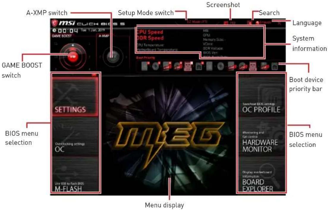
EZ Mode
At EZ mode, it provides the basic system information and allows you to configure the basic setting. To configure the advanced BIOS settings, please enter the Advanced Mode by pressing the Setup Mode switch or F7 function key.
- GAME Boost switch (optional) - click on the center button to switch the GAME BOOST be controlled by software (SW) or hardware (HW). The inner circle represents the current stage of hardware GAME BOOST and the outer circle stands for software. You can read the abilities of GAME Boost by clicking on the question mark in the right-bottom corner. This function will only be available if the installed processor supports this function.

Important
Please don't make any changes in OC menu and don't load defaults to keep the optimal performance and system stability after activating the GAME BOOST function.
-
A-XMP switch (optional) - click on the inner circle to enable/ disable the A-XMP. Switch the outer circle to select the memory profile if any. This switch will only be available if the installed processor and memory modules support A-XMP function.
-
Setup Mode switch - press this tab or the F7 key to switch between Advanced mode and EZ mode.
-
Screenshot - click on this tab or the F12 key to take a screenshot and save it to USB flash drive (FAT/ FAT32 format only).
-
Search - click on this tab or the Ctrl+F keys to enter the search page. It allows you to search by BIOS item name. Move the mouse over a blank space and right click the mouse to exit the search page.

Important
In search page, only the F6, F10 and F12 function keys are available.
-
Language - allows you to select language of BIOS setup.
-
System information - shows the CPU/ DDR speed, CPU/ MB temperature, MB/ CPU type, memory size, CPU/ DDR voltage, BIOS version and build date.
-
Boot device priority bar - you can move the device icons to change the boot priority. The boot priority from high to low is left to right.
-
Information display - click on the CPU, Memory, Storage, Fan Info and Help buttons on left side to display related information.
-
Function buttons - enable or disable the LAN Option ROM, ErP Ready, AHCI/ RAID, Indication LED Control, BIOS UEFI/CSM Mode and RGB Light Control by clicking on their respective button.
-
M-Flash - click on this button to display the M-Flash menu that provides the way to update BIOS with a USB flash drive.
-
Hardware Monitor - click on this button to display the Hardware Monitor menu that allows you to manually control the fan speed by percentage.
-
Favorites - press the F3 key to enter Favorites menu. It allows you to create personal BIOS menu where you can save and access favorite/ frequently-used BIOS setting items.
-
Default HomePage - allows you to select a BIOS menu (e.g. SETTINGS, OC...,etc) as the BIOS home page.
- Favorite1-5 - allows you to add the frequently-used/ favorite BIOS setting items in one page.
-
To add a BIOS item to a favorite page (Favorite 1~5)
-
Move the mouse over a BIOS item not only on BIOS menu but also on search page.
- Right-click or press F2 key.
- Choose a favorite page and click on OK.
- To delete a BIOS item from favorite page
- Move the mouse over a BIOS item on favorite page [Favorite 1~5]
- Right-click or press F2 key.
- Choose Delete and click on OK.
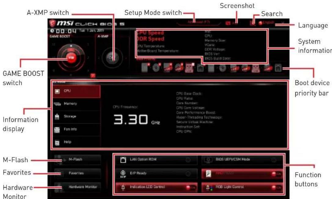
Advanced Mode
Press Setup Mode switch or F7 function key can switch between EZ Mode and Advanced Mode in BIOS setup.
BIOS menu selection - the following options are available:
-
SETTINGS - allows you to specify the parameters for chipset and boot devices.
-
OC - allows you to adjust the frequency and voltage. Increasing the frequency may get better performance.
-
M-FLASH - provides the way to update BIOS with a USB flash drive.
-
OC PROFILE - allows you to manage overclocking profiles.
-
HARDWARE MONITOR - allows you to set the speeds of fans and monitor voltages of system.
-
BOARD EXPLORER - provides the information of installed devices on this motherboard.
-
Menu display - provides BIOS setting items and information to be configured.
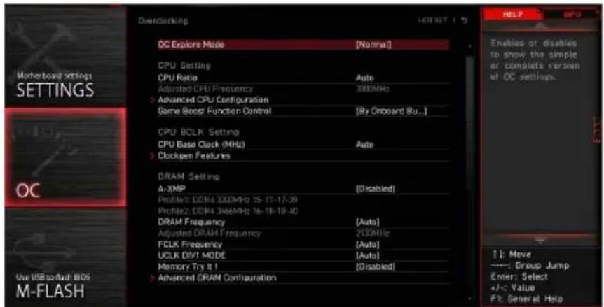
OC Menu
This menu is for advanced users who want to overclock the motherboard.

Important
Overclocking your PC manually is only recommended for advanced users.
Overclocking is not guaranteed, and if done improperly, it could void your warranty or severely damage your hardware.
If you are unfamiliar with overclocking, we advise you to use GAME BOOST function for easy overclocking.
The BIOS items in OC menu will vary with the processor.

OC Explore Mode [Normal]
Enables or disables to show the normal or expert version of OC settings.
[Normal] Provides the regular OC settings in BIOS setup.
[Expert] Provides the advanced OC settings for OC expert to configure in BIOS setup.
Note: We use * as the symbol for the OC settings of Expert mode.
![MSI MEG X570 ACE - OC Explore Mode [Normal] - 1](/content/2026/03/534383/images/9278e52ed8618a6f50ee7573a45c7772c198c4e861bef57e75199ee19c97a056.jpg)
CPU Ratio [Auto]
Sets the CPU ratio that is used to determine CPU clock speed. This item can only be changed if the processor supports this function.
![MSI MEG X570 ACE - CPU Ratio [Auto] - 1](/content/2026/03/534383/images/c75799ccac818f94dd9854805d7111e013f98334ac80c92c2e8f721ba5b79c90.jpg)
Advanced CPU Configuration
Press Enter to enter the sub-menu. User can set the parameters about CPU power/ current. The system may become unstable or unbootable after changing the parameters. If it occurs, please clear the CMOS data and restore the default settings.

Game Boost Function Control [By Onboard Button]
Sets to enable the Game Boost Function by virtual button in BIOS or physical button on motherboard.
![MSI MEG X570 ACE - Game Boost Function Control [By Onboard Button] - 1](/content/2026/03/534383/images/8118c9caac116aa9e460f2e1f4c90604a2407f0012f2bf3ef1533f590f260d47.jpg)
A-XMP [Disabled]
Please enable A-XMP or select a profile of memory module for overclocking the memory. This item will be available when the installed processor, memory modules and motherboard support this function.
DRAM Frequency [Auto]
Sets the DRAM frequency. Please note the overclocking behavior is not guaranteed.
FCLK Frequency [Auto]
- Sets the FCLK frequency (Internal Data Fabric clock of DRAM). Please note the overclocking behavior is not guaranteed.
UCLKDIV1Mode[Auto]
Sets UCLK (Internal memory controller clock) mode.
Memory Try It ! [Disabled]
It can improve memory compatibility or performance by choosing optimized memory preset.
Adjusted DRAM Frequency
Shows the adjusted DRAM frequency. Read-only.
Advanced DRAM Configuration
Press Enter to enter the sub-menu. User can set the memory timing for each/ all memory channel. The system may become unstable or unbootable after changing memory timing. If it occurs, please clear the CMOS data and restore the default settings. (Refer to the Clear CMOS jumper section to clear the CMOS data, and enter the BIOS to load the default settings.)
DigitALL Power
Press Enter to enter the sub-menu. Controls the digital powers related to CPU PWM.
CPU Loadline Calibration Control [Auto]
The CPU voltage will decrease proportionally according to CPU loading. Higher load-line calibration could get higher voltage and good overclocking performance, but increase the temperature of the CPU and VRM. If set to Auto, BIOS will configure this setting automatically.
CPU Over Voltage Protection [Auto]
Sets the voltage limit for CPU over-voltage protection. If set to Auto, BIOS will configure this setting automatically. Higher voltage provides less protection and may damage the system.
CPU Under Voltage Protection [Auto]
Sets the voltage limit for CPU under-voltage protection. If set to Auto, BIOS will configure this setting automatically. Higher voltage provides less protection and may damage the system.
CPU Over Current Protection [Auto]
Sets the current limit for CPU over-current protection. If set to Auto, BIOS will configure this setting automatically.
[Auto] This setting will be configured automatically by BIOS.
[Enhanced] Extends the current range for over-current protection.
CPU NB Loadline Calibration Control [Auto]
The CPU-NB voltage will decrease proportionally according to CPU-NB loading. Higher load-line calibration could get higher voltage and good overclocking performance, but increase the temperature. If set to Auto, BIOS will configure this setting automatically.
CPU Voltages control [Auto]
These options allow you to set the voltages related to CPU. If set to Auto, BIOS will set these voltages automatically or you can set it manually.
DRAM Voltages control [Auto]
These options allow you to set the voltages related to memory. If set to Auto, BIOS will set these voltages automatically or you can set it manually.
Memory Changed Detect [Enabled]*
Enables or disables the system to issue a warning message during boot when the memory has been replaced.
[Enabled] The system will issue a warning message during boot and then you have to load the default settings for new devices.
[Disabled] Disables this function and keeps the current BIOS settings.
CPU Specifications
Press Enter to enter the sub-menu. This sub-menu displays the information of installed CPU. You can also access this information menu at any time by pressing [F4]. Read only.
CPU Technology Support
Press Enter to enter the sub-menu. The sub-menu shows the key features of installed CPU. Read only.
MEMORY-Z
Press Enter to enter the sub-menu. This sub-menu displays all the settings and timings of installed memory. You can also access this information menu at any time by pressing [F5].
DIMMx Memory SPD
Press Enter to enter the sub-menu. The sub-menu displays the information of installed memory. Read only.
CPU Features
Press Enter to enter the sub-menu.
Simultaneous Multi-Threading [Enabled] (optional)
Enables/ disables the AMD Simultaneous Multi-Threading. This item appears when the installed CPU supports this technology.
Global C-state Control [Enabled] (optional)
Enables/ disables IO based C-state generation and DF C-states.
Opcache Control [Auto] (optional)
Enables/ disables Opcache. Opcache stores recent decode instruction to save the decoding time when the instruction is repeated. And it may increase the CPU performance and reduce the power consumption slightly.
I0MMU Mode (optional)
Enables/disables the I0MMU [I/O Memory Management Unit] for I/O Virtualization.
Spread Spectrum (optional)
This function reduces the EMI (Electromagnetic Interference) generated by modulating clock generator pulses.
[Enabled] Enables the spread spectrum function to reduce the EMI (Electromagnetic Interference) problem.
[Disabled] Enhances the overclocking ability of CPU Base clock.
Important
If you do not have any EMI problem, leave the setting at [Disabled] for optimal system stability and performance. But if you are plagued by EMI, select the value of Spread Spectrum for EMI reduction.
The greater the Spread Spectrum value is, the greater the EMI is reduced, and the system will become less stable. For the most suitable Spread Spectrum value, please consult your local EMI regulation.
Remember to disable Spread Spectrum if you are overclocking because even a slight jitter can introduce a temporary boost in clock speed which may just cause your overclocked processor to lock up.
Relaxed EDC throttling [Auto] (optional)
Relaxed EDC throttling reduces the amount of time the processor will throttle the cores.
[Auto] AMD's recommendation
[Enabled] Reduce the amount of time the processor will throttle.
[Disabled] Part-specific EDC throttling protection enabled.
AMD Cool'n'Quiet [Enabled]
The Cool'n' Quiet technology can effectively and dynamically lower CPU speed and power consumption.
SVM Mode [Enabled]
Enables/ disables the AMD SVM (Secure Virtual Machine) Mode.
BIOS PSP Support [Enabled] (optional)
Enables/ disables the BIOS PSP support. It manages PSP sub-items including all C2P/P2C mailbox, Secure S3, fTPM support.
Power Supply Idle Control [Auto] (optional)
It allows you to select the power-saving control mode for the CPU when all cores are in a non-CO state. If set to Auto, BIOS will configure these settings.
Inhalt
SATA1~4: SATA 6Gb/s Anschlüsse
JFP1, JFP2: Frontpanel-Anschlüsse
| JFP1 | Power Switch | - | + | Reserved |
| + | - | Reset Switch | ||
| Power LED | - | - | - | |
| + | - | HDD LED | ||
| 2 | 1 | |||
| 1 | DD LED + 2 Power LED + | |||
| 3 | HDD LED - | 4 | Power LED - | |
| 5 | Reset Switch | 6 | Power Switch | |
| 7 | Reset Switch | 8 | Power Switch | |
| 9 | Reserved | 10 | No Pin |
| JFP2 | 1 S | Speaker - 2 Buzzer + | ||
| 3 B | Buzzer - 4 Speaker + |
CPU_PWR1~2, ATX_PWR1: Stromanschlüsse
JUSB2~3: USB 3.2 Gen1 Anschlüsse
| JUSB3 10 20 | JUSB2 | ||
| 1 Power 11 USB2.0+ | |||
| 2 USB3_RX_DN 12 USB2.0- | |||
| 3 USB3_RX_DP 13 Ground | |||
| 4 | Ground | 14 | USB3_TX_C_DP |
| 5 | USB3_TX_C_DN | 15 | USB3_TX_C_DN |
| 6 | USB3_TX_C_DP | 16 | Ground |
| 7 | Ground | 17 | USB3_RX_DP |
| 8 | USB2.0- | 18 | USB3_RX_DN |
| 9 | USB2.0+ | 19 | Power |
| 10 | NC | 20 | No Pin |
Wichtig
JUSB4~5: USB 2.0 Anschlüsse
Please don't make any changes in OC menu and don't load defaults to keep the optimal performance and system stability after activating the GAME BOOST function.
Advanced CPU Configuration
Game Boost Function Control [By Onboard Button]
DRAM Frequency [Auto]
FCLK Frequency [Auto]
Adjusted DRAM Frequency
CPU Voltages control [Auto]
DRAM Voltages control [Auto]
CPU Technology Support
Relaxed EDC throttling [Auto] (optional)
Power Supply Idle Control [Auto] (optional)
| JFP1 | Power Switch | - | + | - | Reserved | + | - | Reset Switch |
| Power LED | - | - | - | - | - | - | HDD LED | |
| 2 | 1 | |||||||
| 1 | DD LED + 2 Power LED + | |||||||
| 3 | HDD LED - | 4 | Power LED - | |||||
| 5 | Reset Switch | 6 | Power Switch | |||||
| 7 | Reset Switch | 8 | Power Switch | |||||
| 9 | Reserved | 10 | No Pin |
| JFP2 | 1 S | Speaker - 2 Buzzer + | ||
| 3 B | Buzzer - 4 Speaker + |
Advanced CPU Configuration
▶ Game Boost Function Control [By Onboard Button]
DRAM Frequency [Auto]
FCLK Frequency [Auto]
Adjusted DRAM Frequency
CPU Voltages control [Auto]
DRAM Voltages control [Auto]
CPU Technology Support
Relaxed EDC throttling [Auto] (optional)
Power Supply Idle Control [Auto] (optional)
KOMnoHeNTbMaTepuHcKoI IaTbI 16
Ipoceccopnbic coket 17
CnotbDIMM 18
PCI_E1~5: CnotbI paCnupenHna PCIe 19
M2_1~3:Pa3beMbI M.2 (Klouy M) 21
SATA1-4:Pa3bembl SATA 6Γ6/c. 23
JFP1, JFP2: Pa3bembl nepednei nanei 23
CPU_PWR1~2,ATX_PWR1:Pa3bemblnTaHnna 24
OC1: Khonka GAME BOOST 25
JAUD1:Pa3bem aydno nepednei nanei 26
JUSB1:Pa3bem USB 3.2 Gen 2 Type-C 27
JUSB2-3:Pa3beMbUSB3.2Gen1 27
JUSB4~5:Pa3beMbI USB 2.0. 28
JTPM1:Pa3bemMoDyJIa TPM 28
CPU_FAN1, PUMP_FAN1, SYS_FAN1~5: Pa3bembl BeHTnlaTopoB 29
JCI1:Pa3bEm DaTUnka OTKpbITnK Kopnyca 30
JBAT1:Джампер оочткданьх CMOS [C6pocBIOS] 31
POWER1, RESET1: Khonka nitaHn, Khonka nepe3arpy3kn 31
JRGB1:Pa3bem RGB LED 32
JRAINBOW1~2:Pa3bembl apechblx RGB LED 33
JCORSAIR1:Pa3bemCORSAIR 34
BcTpoeHbIe HndnKaToPbI 35
HndkaTopbIOIaIKN EZ 35
JPWRLED1: INdkaTop noKJIoueHnI NITAHN 35
HndkaTOp OTnaOCHbIX KOIOB 35
Ta6nua weecTnaIauaTnpuHbIX CmBOJIOB 36
Φa3bl 3arpy3kn. 36
Ta6nua oTnaOuHbIX KOIOB 36
YcTaHOBka OC,dpaBepOB n yTnIIT 41
YcTaHOBka Windows 10. 41
YcTaHOBka npaIBepOB 41
YcTaHOBka yTnIIT 41
HacrpoiKaBIOS 42
Bxod B HacTropon BiOS 42
C6pocBIOS 43
06HOBJIeHneBIOS. 43
PexnEM EZ 45
Pexm pa3roHa 47
MeHIOOC 48
ABTOMaTnueckoe BCnIbIbAIOoee dnaIanoROBoe OKHO
Pn noKluohy uctpoCTBa K pa3bemy ayDno NOBNTc DnaJIOROBOE OKHO C npocboon noTBeepntb noKluohoe yctpoCTBO.
KaJdbi pa3bem COOTBeTCTByeTe rO HAcTpOuKam No yMOJuaHnU, KaK NOKa3aHO Ha cIeNyUoSe CTpaHnue
BHMaHne!
I3o6paXeHn npBedeHb ICKHIOHTeJbHO B CnpaBOUYbIX cIeJAX MOryT OTNuYATbcr O T aKTNUeCKNX.
IopKJIIOUeHneHayuHnKOBIMNKpoΦOHa

Подкlioуене Вишeroстpeo усilntеля (Kolohok)
KoMnoHentbI MaTePnHcKoI nlaTbI
Ppoecccopnb cokeT
Ppoeccop AM4
HaNoBepxHocTn npoecccopa AM4
IMeETc30JIoTOu TpeyroIbHnK
JIpynpaBnIbHOY UCTaHOBKn
PpoceCCopa OTHOCHTeNbHO
PpoecCOPHOrO COKeTa
MaTePNHCKo PnAToB. 30JIoTOU
TpeyrolbHnK yKa3bIBaet Ha
KOHTaKT 1.
Bнманne!
M3-3a 0co6eHHocTeApxnteKTypbI npouceccopOB AM4,3ameHa npoueccopa MoKeT npuBecTu K c6pocy Hactpoek B1OS do 3naueHn no ymoJuaHnIO.
RepeyctaHOBkoI nn 3ameHoi npoeccopa, Heo6xOIMO OTKJIIOHTb Ka6eIb nHTAHn.
Ipn yctahOBke npouecoppa o63aTeBHO yCTAHOBnTE npoueccopHbIK KyIep. KyIep, npedctabJIOUs co6oB cnCTemy OxJaXdEHH npoueccoppa, npedotBpaaet neperpeB n obecneuBaET cTabnHyo pa60Ty cnCTembl.
HepeB KJIIOUeHnEM CNCTeMbI NPOBepbTe RepMeTuHOCb COeINHeHnMexKdy npouecccopOM n paDnATOpOM.
NepereB MoKet npuBecn K cepBe3Homy nobpeKeHnIO npoceccopa n MaTePuncko nnatb. Bcerda npOBepa Te pa6OTocncO6HocTb BeHTnIaTopa Iy 3auNTbI npoueCCopa ot nepereBa. Pn yCTaHOBKe KyIepa HaHeCtPe pOBhIn CNoI TepMonactb {nn TepMOeHTy) Ha KpbIshky UCTaHOBLeHHoro npoceccopa IyIyUweHn TennonepeDaun.
EcnBbI npno6peHn OTdIeNbHO npoceccop n npoceccopHny Kynep, noDpo6Hoe ONucaHne yCTaHOBKn CM. B DOKymeHTaCnN B daHHOMy Kynepy.
AHHa cnCTeMHa nIaTa pa3pa6oTaHa c yueTom Bo3MOxHocTn ee «pa3roHa>. Ipeed BblIOJIHeHneM pa3roHa cnCTeMbI y6eIITecb B TOM, YTO BCE KOMnoHEtbl CNCTeMbICMOryTe BOIePkaTb. IpOn3BOJNTeNb He peKOMeHdyet NCNoJb3OBaTb NapaMeTpbl, BblOJaUne 3a IpeJeBt texHnuecknx XapaKTepunctNK UcTPOuCTB. IapaHTna MS! He pacnpocTpahReTcra Ha nobpeJeHnna I npyrnE BO3MOxHbIe NocIeDCTBnI HeHaJIeKaUe 3KcIIpyataun OobpyoDaHnI.
CnotbIDIMM

PekomeHdaaunno yctaHOBKe moyne naTn

BHHMaHHe!
Bcerda yctaHaBnBaIte MOdyIb namrtn cHaayana B Cnot DIMMA2.
B CB83n CO CneuΦKoNcNoIb3OBAHnpeCypcoB YInCeTa,doCTyNbI O6bEm nAmrTu BydET HEMHO MehSe, Yem Obem yctaHOBeHHbI.
Ha ochobe xapaKTepeNtuk npoueccopa, peKOMeHdyeTc yCTaHaBnBaTb HapjKeHne Ha namrtn DIMM meHee 1.35 B. 3TO no3BOJNT 3aunTntb npouecop.
HeKOTOpbIe MoUyIIN pAMrTI np pa3ROHe MOrYT pa6OtaB Ha YaCTOTax HnKe 3aBHeHHo IPOu3BOIDTeJIeM, NocKoJIbKY BbICTabIeMaJ dJa pAmrTu YAcTOTa 3aBNCIT OT uHΦOpMaIuN, 3aIIncAHHO B SPD (Serial Presence Detect). 3aIHTe B BIOS IN BBi6epuTE ONUO DRAM Frequency!, UTo6bl yCTaHOBtB 3aBHeHHyU INI 6OJIee BbICOKyIO qAcTOTy.
Pn yCTaHOBKe nAMrTu BO BCE CNoTbI, a TaKKe npu ee pa3roHe, peKOMeHnyeTcNcNOJIb3OBAtB 6OJe 3ofoekTNBHyU CnCTemy OXnaJxHnnaPamrTu.
OBMECTUMOCTb n CTa6NJIbHOCTb pa6OTbl yCTaHOBNEHHORo MOyJNAmAYn npu pa3ROHe 3aBNCNT OT yCTaHOBNEHHORo IPOeCCOPa N dpyrNX yCTpONCTB.
3-3a orpaHnueHn oHnuaJIbHO nCneuNkaun npoueccopa AM4/ KOHTpOJIpe naMaTn, MOnyI NaMaTn MOryT pa6oTaTb Ha YacToTaX HnKe 3aBHeHNo Ipn3BOJTeJeM npn HacPoJkax No yMOJHaHIO. OOnONHtJIbHyU INHOpMaUHO COBMeCTmBIX MoyJnx NaMaTn MOxHo HaHTn Ha Be6-caTe www.msi.com.
PCI_E1~5: CnotbIpacwnpeHnPa PCIe
| Слот | AMD Ryzen™ 3-rostokоленя | AMD Ryzen™ 2-rostokоленя | Ryzen™ с вида ekартоу Radeonon™ Vega и AMD Ryzen™ 2-rostokоленя с вида ekapтоу Radeonon™ |
| PCI_E1 | PCIe 4.0 x16 | PCIe 3.0 x16 | PCIe 3.0 x8 |
| PCI_E2 | PCIe 4.0 x1 PCIe 3.0 x1 | PCIe 3.0 x1 | |
| PCI_E3 | PCIe 4.0 x8 PCIe 3.0 x8 | Недоступно | |
| PCI_E4 | PCIe 4.0 x1 PCIe 3.0 x1 | PCIe 3.0 x1 | |
| PCI_E5 | PCIe 4.0 x4 PCIe 3.0 x4 | PCIe 3.0 x4 |

BHHMaHHe!
Pn yCTaHOBKe MaccNBHO BundeOkaTbI, Heo6xOJMo NcNoB30BaTb TaKo INHCTpyMeHT, KaK MSI Gaming Series Graphics Card Bolster nla noDepKKn Beca rpaΦnueckon KapTbI n BO n36eKaHne deΦopMaun cNoTa.
IyctahOBKn OJHOn KapTbI paCwnpeHn PAle x16 c ONTUMaNbHO npON3BOJNTeJIbHOCTbIO peKOMeHnyETcNcONb3OBAb CNOT PCI_E1.
RepeyuctaHOBkoN uHn H3BneueHem nLaT paUwpeHna y6eNTecb, YTO Ka6enb nHTAHn OTKIOuEH OT 3NeKTPnueCKoCetn. IpOuyTte DOkymeHTaUN Ha KapTy paUwpeHn N BbINOJHnTe HeO6XoUMbIe DOnONHTeJIbHbIe anppaTHbIe uHn npOrpAMMbIe N3MeHeHn dJaHHo KApTbl.
CnotbPCIe x1 HeIb3a NcNoIb3OBA Tb OJHOBpeMeHHO. Cnot PCI_E2 6ydet HeoctyneH npu yCTaHOBKe KapTbPCIe B Cnot PCI_E4.
Ta6nua nponysckno cnoc6nctn PCIe
06paTntecb K Ta6nue Hnke, YTO6bl yCTaHOBt b ycToiCtBa PCIe.
Для пpoцecpopOB AMD RyzenTM 3- ro nokoJIeHnA
| Слот Однарный 2-Way 3-Way* | |||||
| PCI_E1 (CPU) | @4.0 x16 @4.0 x8 @4.0 x8 | ||||
| PCI_E2 (PCH) | 4.0 x1 - 4.0 x1 - 4.0 x1 - | ||||
| PCI_E3 (CPU) | — @4.0 x8 @4.0 x8 | ||||
| PCI_E4 (PCH) | — 4.0 x1 — 4.0 x1 — | ||||
| PCI_E5 (PCH) | 4.0 x4 | @4.0 x4 | |||
(:Heoctynho,a:CNOTBndeokapTbI,*:ToJIbKOdNraCrossFire)
Для пpouceccopoB AMD RyzenTM 2- ro nokolchenia
| Слот Однарный 2-Way 3-Way* | ||||||
| PCI_E1 (CPU) | a3.0 x16 @3.0 x8 @3.0 x8 | |||||
| PCI_E2 (PCH) | 3.0 x1 - 3 | 0 x1 - 3.0 | x1 - | |||
| PCI_E3 (CPU) | - @3.0 x8 @3.0 x8 | |||||
| PCI_E4 (PCH) | - 3.0 x1 - 3.0 x1 - | 3.0 x1 - | 3.0 x1 | |||
| PCI_E5 (PCH) | 3.0 x4 3.0 x4 @3.0 x4 | |||||
| JFP1 | Power Switch | - | + | Reserved |
| + | - | Reset Switch | ||
| Power LED | - | - | - | |
| + | - | HDD LED | ||
| 2 | 1 | |||
| 1 H | DD LED + 2 Power LED + | |||
| 3 H | DD LED - 4 Power LED - | |||
| 5 | Reset Switch 6 Power Switch | |||
| 7 | Reset Switch 8 Power Switch | |||
| 9 | Reserved | 10 | No Pin |
| JFP2 | 1 S | Speaker - 2 Buzzer + | ||
| 3 B | Buzzer - 4 Speaker + |
CPU_PWR1~2,ATX_PWR1:Pa3beMbI\PITaHn
DaHHbIe pa3bEmbl npedHa3HaueHb I nnoKluoyenra 6loka nntaHnA TxA.

| CPU_PWR1~2 | |||
| 1 Ground 5 | +12V | ||
| 2 Ground 6 | +12V | ||
| 3 Ground 7 | +12V | ||
| 4 Ground 8 | +12V | ||
| 12 24 13 ATX_PWR1 | 1 +3.3V 13 +3.3V | ||
| 2 +3.3V 14 -12V | |||
| 3 Ground 15 Ground | |||
| 4 +5V 16 PS-ON# | |||
| 5 Ground 17 Ground | |||
| 6 +5V 18 Ground | |||
| 7 Ground 19 Ground | |||
| 8 PWR OK 20 Res | |||
| 9 5V SB 21 +5V | |||
| 10 +12V 22 +5V | |||
| 11 +12V 23 +5V | |||
| 12 +3.3V 24 Ground |

BHHMaHHe!
IJIy oecneuHn cta6nBHO pa60bI CnCTeMHo nIaTb npOBepbTe HAdexKHOCTb NOkNIOUeHn BCEx Ka6ene NtAHn K 6NoKy NtAHn ATX.
OC1: Khonka GAME BOOST
3Ta KhoNka N03BOJareT BpyHyIO BbI6paTb yPoBeH pa3roHa npoceccopa, Naunna C ypoBnA 0 (no ymoJIuaHnIO) do ypoBnA 11 (ekCTpeMaIbHbI). HanpJxHeHne uactota npoeCCopa bdyet peryIInpoBaTcABTOMaTueckn Pocne BKIOUeHnKOMNbIOTepa. 3Ta KhoNka DoCTyHnA ToIbKO B clyuae, ecnn UcTaHOBnEH MoDyIb IamrTn C NoepKKo DaHHOf yHKcUN,

IcnoJb3ObaHne KHonKn GAME BOOST
CPU_FAN1, PUMP_FAN1, SYS_FAN1~5: Pa3bemblBeHTnIaTOpOB
Pa3bembl BeHTnIaTOPOB MoXHO pa3deHNTb Ha Dba TINa: c PWM (PulseWidth Modulation) ynpabLeHnEM n ynpabLeHnEM NOCToHHbIM TOKOM. Pa3bembl BeHTnIaTOPOB C PWM ynpabLeHnEM IMeOT KOHTaKT C NOCToHHbIM HAnpJxKeHnEM 12B, a Takke KoHTaKT C cnrHaIOM ynpabLeHnR cKOpocTbIO BpaUeHnR. YnpabLeHnE CKOPoCTbIO BpaUeHnR BeHTnIaTOPOB C ynpabLeHnEM NOCToHHbIM TOKOM, OcyueeCTBnIeTcApe3 COOTBeTCBvOuIe pa3bembl NytEm N3MeHeHnR BeNUnHbI HAnpJxKeHnR. IJIa NaCTPOBKn peKIma pa60tBI BeHTnIaTOPA BpyHyIO (PWM nnn DC), cNeDuTe yKa3aHnRm HnKe.
Pa3bem BENTnIaTopa c ynpabJeHneM PWM no yMOJIaHHIO

CPU_FAN1/PUMP_FAN1
Pa3bem BeHTnJIaTopa c ynpabIeHneM DC no yMOJUHaHIO

SYS_FAN1&3

SYS_FAN2,4&5
IpeekloueHne pexmOB pa60tbl n ckopoctn BpaueHn BeHTnilaTopa
B MeHIO BIOS > HARDWARE MONITOR Bbl MoXKeTe Bbl6paTb peKINB pa60Tb BEHTnIaTopa: PWM nnn DC, a TaKke HacTpOntb erO CKOpocTb BpaueHnA.
Bb6epntepxIM PWM nIN DC
Bbl mokeTe perylnpoBaTb CKOpocTb BpaueHnBEHTnIaTopa B 3aBNCIMOCTH OT TeMpePaTypbI npoceccopa NyTem I3MeHeHn NOLOKeHHra PaadneHTbIX ToeK.

BHMMaHHe!
Y6eHntecb, yTO BeHTnIaTOpbI pa6oTaH TnpaBnIbHo nocne Bbl6opa peKIma PWM/ DC.
Ha3NaueHne KOHTaKTOB pa3beMa IJI NOkIIOUeHnBeHTnJIaTopa
| Ha3NaYeHne KOHTaKToB pa3bema Дд ржIMа PWM | |||
| 1 G | round 2 +12V | ||
| 3 S | ense 4 Speed | Control | Signal |
| №3начениkoNTаКТовразьема干嘛е рек imma DC | |||
| 1 Gound 2 Voltage Control | |||
| 3 Sense 4 NC |
JCI1: Pa3bem daTUnka OTKpbITnK Kopnyca
BcTpoeHbIe INdNkAToPbI
HaHHbIe CBeToOnOdbI NOKa3bIBaOT COCTOHN MaTePNHCKO INaTbl.

CPU- npoeccop He o6napykeH nn noBpeKdEh.
DRAM - namTb DRAM He o6HapyKeHa nn NOBpeKdEHa.
VGA-BndeokapTa He o6HapyKeHa nIIN NOBpeKDeHa.
B00T - yctpoiCTBO 3aIpy3Kn He o6HapyKeHo nnn noBpeXdEHO.
Pre-EFI Initialization (PEI) - INHnuaJna3aunpaTn
Driver Execution Environment (DXE) - INHnucnnaizouo6opudobnna
Boot Device Selection (BDS) - HabtpoRKn CnCTeMbI, NOlb3OBATeNbCKN INTEppeicdo 3aRpy3Kn OC & BbI6Op 3aRpy3OuHOro yCTpoiCtBa (CD/DVD, HDD, USB, Network, Shell,...)
Ta6nua oTnaOuHbIX KOIOB
Порpecc-Коды SEc
Pporpecc-KoDbI BOCCTaHOBJIeHnA
KoIbIOUH6OK BOCCTaHOBJIeHn
| F8 Boc | Стоноvealно PPI He достусяно |
| F9 | Кансuya BOCSTановленno He найдано |
| FA Hepehna Kaçcuya BOCSTановленno | |
| FB - FF Reserved for future AMI error codes | |
KoIbI COCTOHN ACPI
Cleyuoune KoBIOBnIOTc nOcNe 3aRpy3Kn I nepeXoJa OepauOnHNo cnCTeMbIBpeKIMbIACPI.
Advanced CPU Configuration
HaKmnte Enter IJI BxOda B NOJMeHIO. Nolb3OBaTeIb MOKeT HAcTpOntb TaMnHrN IJI MoUHocTN /ToKa Ipoueccopa.CnCTema MoKeT pa6oTaTB HeCTa6nIbHO IJI He 3arpyKaTcBcI NocIe N3MeHeHn TaMnHroB NaMyTn. EcIn CnCTema pa6oTaET HeCTa6nIbHO, NoXaNoYcTa, OOnCTtNe DaHHbIe CMOS IN BOCCTaHOBNTe HaCTPOIN IO yMOJuaHnIO.
▶ Game Boost Function Control [By Onboard Button]
YctaHabnBaet CnoC6 BkIoueHna FyHKcNn GAME BOOST: c NOMOuBbU BnptyaJIbHO KHOJKN B HaCTpoiKax BIOS nIIN C NOMOuBIO H3NueCKoN KHOJKN Ha MaTePNHcKo Pnate.
A-XMP [Disabled]
BkIIOHTe A-XMP nIIb BbI6epnte npoΦnIb MOyIaMraTn IJIpa3roHa. DaHbI INyHKT IOCTUpeH, KOrda yCTaHOBLeH MoyIb NaMraTn, PPOUecCopa N MaTePHNcKo INlaTbIC NOdEPRKKo DAHHOJ FyHKcUN.
DRAM Frequency [Auto]
YctaHOBka yacToBi namrDrAM. O6paTne BHHMaHHe, YTO BO3MOXHOCTb ycNeuHoro pa3roHa He rapaHTnpyetc.
FCLK Frequency [Auto]
YCTAHOBka YacToTbI FCLK (TaKTOBa YacToTa Internal Data Fabric nIy DRAM). 06paTInTe BHNMaHHe, yTO BO3MOxHocTh yCneUHO rpaHTnpyeTc.
UCLK DIV1 Mode [Auto]
YctaHOBka peKIma UCLK (TaKTobaa Yactota KoHTpOJIepa BHyTppeHne IamrTn).
Memory Try It ! [Disabled]
I03BOJAE T ynyuHTb COBMeCTHMOCTb namrTu I PON3BOJNTeJIbHOCTb, Nytem Bbl6opa Han6Olee ONTImaJIbHOro Ipceceta.
Adjusted DRAM Frequency
Ioka3bIbaeTeKyuUyO uactOTy npouecoppa.3To 3HaueHne HeIb3n3MeHraTb.
Advanced DRAM Configuration
HaKMTe Enter IJI BxOda B NOJMeHIO. IOnb3OBaTeJIb MoKeT HaCTpOHT b TaIMnHrI dJI KaKdOrO KaHana NaMaTn. CnCTema MoKeT pa6oTaB HeCTa6NlBHO II He 3aRpyKaTbCn OcNe N3MeHeHn TaMnHROB NaMaTn. EcII nCtema pa6oTaET HeCTa6NlBHO, NoXaYnCTa, OuNCtnte daHHbIe CMOS u BOCCTaHOBnte HAcTPOKN IO yMOJUaHnIO. [CM. Nepembyka ONUCTKn DaHHbIX CMOS/pa3deJI KHOKN IJIy ONUCTKn DaHHbIX CMOS u BXoB B BIOS, YTO6bl 3aRpy3NTb HaCTPOKN IO yMOJUaHnIO.]
DigitALL Power
HaKmTe Enter IyBxAoDa B NOMeHIO. FyHKuY npaBnE TcENMa NITaHn, CB3aHHbIMn C PWM npoueccopa.
CPU Loadline Calibration Control [Auto]
HaipjxHHe Ha npocceope yMeNbShaetc npOpOpunHObHo, B 3aBnCIMoCTn OTeero 3arpy3Kn. NobbiweHne 3NaeHna Load-line Calibration npINBOiNT K NOBbiSeHIO HaipjxHNe I npOn3BOiNTeIbHOCTn npn pa3roHe, Ho n yBeJIuHBAeT Tempepaty npoccecopa n VRM. Pnp ycTaHOBKe B Auto, BIOS ycTaHOBHT daHHbI npapaMeTp aBTOMaTnueckn.
CPU Over Voltage Protection [Auto]
YcTaHabINBaET BepXHIO rpaHnCy MaKcMmaIbHOrO HApJxKeHnI dJI 3aIITbI npoueccopa OT NOBbIweHHoro HapJxKeHn. Ecnn YcTaHOBLeHo Auto, BIOS abTOMaTHueCKn HaCTpont 3TOT npaMeTp. Yem Bblwe 3HaueHne, TEm HnKe CTepeHb 3aUHTbl N Bblwe BepoA THOCb BblXOda CNCTeMb I3 CTPoR.
CPU Under Voltage Protection [Auto]
YcTaHabNtBaeT HxHIO rpaHcy HaPjXeHn IJy 3aUHTbI npOceCopa OT IOHxKeHHOro HapjXeHn. Ecnn YcTaHOBJeHO Auto, BIOS aBTOMaTnueckn HAcTpOIT 3TOT npaMeTp. Yem BbIwe 3HaueHne, TeM Hxke CTepeHb 3aUHTbI N BblSe BepoTHOCTb BblOda CNCTeMbI IN 3 CTPOJ.
CPU Over Current Protection [Auto]
YcTaHaBJIbNAeT ORpaHnueHHe NO MaKcMmaJbHOMy TOKy JIaJr 3aUHTbl npOceccopa. Ipn yCTaHBKe B Auto, BIOS aBTOMaTHueckn HacTpont 3TOT napaMeTp.
[Auto] ΘOT npaMeTp 6ydeT HAcTpoeH aBTOMaTHueCKN C NOMOuBIO BIOS.
[Enhanced] Pacunparet orpaHneHne no TOKy ot neperpy3kn no TOKy.
CPU NB Loadline Calibration Control [Auto]
Ha npjxehne Ha CPU-NB ymeNbwaetc nponopuznoHaIbHo, B 3aBnCmOCTN OT er0 3arpy3kn. NobuweHne 3naueHnla Load-line Calibration npnbODnt K NOBbiweHIO Ha npjxehne n npo3BODnteJIbHOCTn npn pa3roHe, HO u YBeInuBaET Tempeatypc cnCTembl. PpN ycTaHOBKe B Auto, BIOS ycTaHOBT DaHHbI napametp aBTOMaTnueckn.
CPU Voltages control [Auto]
3TNnnapaMeTpbl N03BOJIAOT Bam 3aDaTb HAnpJxHnra, CB83aHHbIe C npouceccopom. Pn yCTaHOBKe B Auto, BIOS ycTaHOBnT HAnpJxHnra ABTomatUcckn. Bb TaKke MoKeTe HaCTpoNTb HAnpJxHnra BpyHyIO.
DRAM Voltages control [Auto]
3TN napaMeTpbl NO3BOJHOT Bam 3aJaTb HnprjKeHnra, CBraaHHbIe C naMaTbIO.
Ppnu yCTaHOBKe B Auto, BIOS yCTaHOBNT HnprjKeHnra ABTomatNueckn. Bbl TaKke MOKeTe HAcTPOntb HnprjKeHnra BpyHyIO.
Memory Changed Detect [Enabled]*
BkIIOUeHne IIN BBKIIIOUeHne npedynpeKdaIOuX COo6ueHn npn 3aRpy3Ke cnCTembl, KOrda npoceccop IIN namr8b6bIIN 3aMeHeHbl.
[Enabled] CnCTema BbIaet npedynpejckHe BO Bpem 3arpy3Kn. Tpe6yeTc3arpy3ntb HactpoNkNo yMOJuaHnIO dJe HOBbIX ycTpoNCTB.
[Disabled] BbIKHueHne 3ToI ΦyHKnN u coXpaHHeHne TeKyuNX HAcTpoek BIOS.
CPU Specifications
HaXMMTe Enter nBxOa B noDMHeH. B 3TOM noDMHeH npEcdTabNeHa HOpMaun OyCTaHOBHeHHom IpoueCCope. IJn PpOCMOTpa 3ToI HOpMaun B JIO6oe BpeM HaXMMTe Ha KhoNky [F4]. 3TO 3HaueHne HeJIb3r N3MeHrTb.
CPU Technology Support
HaKmTe Enter IJI BxOJa B IOJMeHIO. B daHHOM IOJMeHIO OTO6paKaIOTc OCHOBhIE cyHKUIN, NOIDepXnBaembIe yCTaHOBJIeHHbIM npOueccopom. 3To 3HaueHHe HeIb3r N3MeHrTb.
MEMORY-Z
HaXMMTe Enter IЯ BxOda B NOmEHo. B NOmEHIO BbIeJIeHbI BCE napaMeTpbl TaimMHn yCTaHOBJIeHHo namrTn.ДЯ npocMOTpa 3ToI INΦOpMauN B IIO6oe BpeM HaXMMTe Ha KhoNky [F5].
▶DIMMx Memory SPD
HaKMTe Enter IyBxOa B NOMeHIO. 3TO NOMeHIO NOKa3bIBAeT HOpMaunio 06 yCTaHOBHeHHo NaMrtn. 3TO 3HaueHne HeIb3r N3MeHrTb.
CPU Features
HaKmTe Enter IJIy BXOa B IOMeHIO.
Simultaneous Multi-Threading [Enabled] (onLnoHaIbHo)
BkIoueHne nnn BbIKIOueHne AMD Simultaneous Multi-Threading. 3ToT nyHK TNOABBLAETc npu yCTaHOBe IPOUecCopa C NOIDepKKoD aHHO fYHKcUN.
Global C-state Control [Enabled] (onuHaIbHo)
BkIIOUeHne IIN BbIKIOUeHne IO based C-state generation n DF C-states.
Opcache Control [Auto] (onuHaJIbHo)
BkIIOUeHne IIN BbIKIOUeHne Opcache. Opcache coXpaHreT NocLeHne KOMaHdbI DeKOIpOBaHnI dIra COKpaIeHnI BpeMeHn IcNoJIHeHn IOBTOHOKOMaHdbI. BkIOUeHne DaHHoI cyHKuIM MoKeT yBeJIuHTb Ipon3BOIDTeNbHOCTb IpOuceccopa n HEmHO rCHN3NTb 3HeprONOTpe6JIeHne.
IOMMU Mode (onuohalbHo)
Включени Или Выключене IOMMU (I/O Memory Management Unit) Д�� I/O Virtualization.
Spread Spectrum (onznoHaJIbHo)
DaHHa yHKnUy MeHbWaaet EMI (3JeKTpomarHHTbIe NOMEXN), Bbl3BaHHbIE KOle6aHnMIMnYbCHOrReHepaTOpa TaKTOBbIX CnHaIOB.
[Enabled] BkIIOUeHHe 3ToI ΦyHKcUN dJa yMeHbUeHnA 3JIeKTPOMaRHTNbIX NOMex.
[Disabled] YBelenuBaet Bo3MoXHocTn pa3roHa 6a3OBOr TaKTOBOy. YaCTOTbI npoueccopa.
BHMaHne!
Ecn npo6nemblc nomexamnu OTCyTCTBYOT, OCTaBbTe 3NaueHne B [Disabled] dIyIywei cta6nIbHOCTN I npOIN3BOIDNTeINbHOCTN. Ondako, ecnn BO3HnKaIO TJIeKTPomarHHTbIe NOMEXN, BKIOUHTe napaMeTp Spread Spectrum dIra nx yMeHbWeHnI.
Hem 60nbwe 3NaueHne Spread Spectrum, Tem Hnke 6ydeT ypoBHeb 3NeKTpOMaHHTbIX NOMex, HO CnCTema CTAHet MeHee Cta6nIbHOJ. IJIa BblOpa NOxOJaero 3NaueHnra Spread Spectrum, CBepbTeCb CO 3NaueHnmaMn ypoBHe J3NeKTpOMaHHTbIX NOMex, yCTaHOBNeHHbIX 3aKOHoDaTeNbCTBOM.
He 3a6ydbTe 3anpeTntb nCNoB3OBAHne fynKcunn Spread Spectrum, ecN Bbl «pa3roHareTe» CnCTeMHyIO PnAly. 3TO Heo6xOIMo, TaK KaK daKe He6oJbWOn Ipe6e3r CnHnAJa TAKTOBOrO rHePaTopa MoXe TnpuBeCTn K OTKa3y pa3oRHaHHoro npouceccopa.
▶Relaxed EDC throttling [Auto] (onционьно)
Relaxed EDC throttling yMeHbShaET BpeMa TpOttTnHra Jaepa IpoUeCCopa.
[Auto] PeKOMeHIOBaHO AMD
[Enabled] Umehbwaet Bpem TpoTTnHra npoceccopa.
[Disabled] BkIIOaET cneuaJIbHyIO qAcTHuHyIO 3auNTy EDC TpoTTInHra.
AMD Cool'n'Quiet [Enabled]
TexHOrnCool'n'Quietno3BoJraTaeKtNBHOINHaMuecknN3MeHrTa ChToTyCPUu3HeprnonoTppe6JeHneCnCTembl.
SVM Mode [Enabled]
Вкlioуени пль Вькючени AMD SVM (Secure Virtual Machine) Mode.
BIOS PSP Support [Enabled] (onционьно)
BkIoueHne Inn BbIKIOueHne BIOS PSP, KOtOpbI ynpabIaTe TNOdnyHKTaMn PSP,BKIOUyA BCE NOuTOBBe IuNKn C2P /P2C, Secure S3 n noDepKky fTPM.
Power Supply Idle Control [Auto] (onuHaIbHo)
FCC Compliance Statement
Note: This equipment has been tested and found to comply with the limits for a Class B digital device, pursuant to part 15 of the FCC Rules. These limits are designed to provide reasonable protection against harmful interference in a residential installation. This equipment generates, uses and can radiate radio frequency energy and, if not installed and used in accordance with the instructions, may cause harmful interference to radio communications. However, there is no guarantee that interference will not occur in a particular installation. If this equipment does cause harmful interference to radio or television reception, which can be determined by turning the equipment off and on, the user is encouraged to try to correct the interference by one or more of the following measures
Reorient or relocate the receiving antenna.
- Increase the separation between the equipment and receiver.
- Connect the equipment into an outlet on a circuit different from that to which the receiver is connected.
- Consult the dealer or an experienced radio/TV technician for help.
Caution: Changes or modifications not expressly approved by the party responsible for compliance could void the user's authority to operate the equipment.

Tested to comply with FCC standards FOR HOME OR OFFICE USE
This device complies with part 15 of the FCC Rules. Operation is subject to the following two conditions: (1) This device may not cause harmful interference, and (2) this device must accept any interference received, including interference that may cause undesired operation.
CE Conformity

Products bearing the CE marking comply with one or more of the following EU Directives as may be applicable:
RED 2014/53/EU; Low Voltage Directive 2014/35/EU; EMC Directive 2014/30/EU; RoHS Directive 2011/65/EU. Compliance with these directives is assessed using applicable European Harmonized Standards. The point of contact for regulatory matters is MSI, MSI-NL Eindhoven 5706 5692 ER Son.
B国机(有国

i
i
i
KlansB情報技術裝置

Batteries, battery packs, and accumulators should not be disposed of as unsorted household waste. Please use the public collection system to return, recycle, or treat them in compliance with the local regulations.
Taiwan:

廢電池請回收
For better environmental protection, waste batteries should be collected separately for recycling or special disposal.
California, USA:

The button cell battery may contain perchlorate material and requires special handling when recycled or disposed of in California.
For further information please visit: http://www.dtsc.ca.gov/hazardouswaste/perchlorate/
CAUTION: There is a risk of explosion, if battery is incorrectly replaced. Replace only with the same or equivalent type recommended by the manufacturer.
Chemical Substances Information
In compliance with chemical substances regulations, such as the EU REACH Regulation (Regulation EC No. 1907/2006 of the European Parliament and the Council), MSI provides the information of chemical substances in products at: http://www.msi.com/html/popup/csr/evmtprtt_pcm.html
Environmental Policy
The product has been designed to enable proper reuse of parts and recycling and should not be thrown away at its end of life.
- Users should contact the local authorized point of collection for
recycling and disposing of their end-of-life products.
- Visit the MSI website and locate a nearby distributor for further recycling information.
- Users may also reach us at gpcontdev@msi.com for information regarding proper Disposal, Take-back, Recycling, and Disassembly of MSI products.

WEEE (Waste Electrical and Electronic Equipment) Statement
ENGLISH
To protect the global environment and as an environmentalist, MSI must remind you that...


Under the European Union ("EU") Directive on Waste Electrical and Electronic Equipment, Directive 2002/96/EC, which takes effect on August 13, 2005, products of "electrical and electronic equipment" cannot be discarded as municipal wastes anymore, and manufacturers of covered electronic equipment will be obligated to take back such products at the end of their useful life. MSI will comply with the product take back requirements at the end of life of MSI-branded products that are sold into the EU. You can return these products to local collection points.
DEUTSCH
This product complies with the "India E-waste (Management and Handling) Rule 2011" and prohibits use of lead, mercury, hexavalent chromium, polybrominated biphenyls or polybrominated diphenyl ethers in concentrations exceeding 0.1 weight % and 0.01 weight % for cadmium, except for the exemptions set in Schedule 2 of the Rule.
This device is restricted to indoor use when operating in the 2.4GHz, 5GHz frequency band.
Products with radio functionality [EMF]
This product incorporates a radio transmitting and receiving device. For computers in normal use, a separation distance of 20~cm ensures that radio frequency exposure levels comply with EU requirements. Products designed to be operated at closer proximities, such as tablet computers, comply with applicable EU requirements in typical operating positions. Products can be operated without maintaining a separation distance unless otherwise indicated in instructions specific to the product.
Restrictions for products with radio functionality

CAUTION: IEEE 802.11x wireless LAN with 5.15-5.35 GHz frequency band is restricted for indoor use only in all European Union member states, EFTA (Iceland, Norway,
Liechtenstein), and most other European countries (e.g., Switzerland, Turkey, Republic of Serbia). Using this WLAN application outdoors might lead to interference issues with existing radio services.
Radio frequency bands and maximum power levels
Features :802.11 a/b/g/n/ac, BT
Frequency Range :2.4GHz, 5GHz
Modulation :FHSS, DSSS, OFDM
Power Output :10, 20, 23
Channel Band Width :1, 5, 20, 40, 80MHz
msi Micro-Star Int' L Co.,Ltd. Copyright © 2020 All rights reserved. The MSI logo used is a registered trademark of Micro-Star Int' L Co., Ltd. All other marks and names mentioned may be trademarks of their respective owners. No warranty as to accuracy or completeness is expressed or implied. MSI reserves the right to make changes to this document without prior notice.
Revision History
Europe Version 1.0, 2019/05, First release.
Europe Version 1.1, 2019/07, updated release.
Europe Version 1.2, 2020/07, updated release.
Technical Support
If a problem arises with your system and no solution can be obtained from the user guide, please contact your place of purchase or local distributor. Alternatively, please try the following help resources for further guidance.
- Visit the MSI website for technical guide, BIOS updates, driver updates, and other information: http://www.msi.com
- Register your product at: http://register.msi.com