
MEG X299 Creation - Motherboard MSI - Free user manual and instructions
Find the device manual for free MEG X299 Creation MSI in PDF.


| Product Type | Motherboard |
| Brand | MSI |
| Model | MEG X299 Creation |
| Chipset | Intel X299 |
| Socket | LGA 2066 |
| Form Factor | ATX |
| Dimensions (W x D) | 30.5 cm x 27.2 cm |
| Weight | 1.2 kg |
| Memory Support | Quad-channel DDR4, up to 128GB (4 DIMMs) |
| PCIe Slots | 4 x PCIe 3.0 x16 (supports SLI/CrossFire) |
| M.2 Slots | 3 x M.2 (M key, PCIe 3.0 x4 / SATA) |
| SATA Ports | 8 x SATA 6 Gb/s |
| USB Ports (Rear I/O) | 1 x USB 3.1 Gen2 Type-C, 8 x USB 3.1 Gen1, 2 x USB 2.0 |
| Networking | Intel Gigabit LAN, Intel Wi-Fi 6 AX200 (802.11ax), Bluetooth 5.0 |
| Audio | Realtek ALC1220 7.1-Channel HD Audio |
| Power Connectors | 1 x 24-pin ATX, 2 x 8-pin CPU |
| Supported CPUs | Intel Core X-series (Skylake-X, Kaby Lake-X, Cascade Lake-X) |
| LED Lighting | Mystic Light RGB (onboard LEDs + header) |
| Care and Cleaning | Use compressed air or isopropyl alcohol on a lint-free cloth. Avoid liquid drips. |
| Safety Precautions | Use ESD wrist strap. Disconnect power before installation. Handle components by edges. |
| Spare Parts / Repairability | No user-serviceable parts. Contact MSI support for repairs. |
| Warranty | 3 years limited (check local regulations) |
Frequently Asked Questions - MEG X299 Creation MSI
User questions about MEG X299 Creation MSI
0 question about this device. Answer the ones you know or ask your own.
Ask a new question about this device
Download the instructions for your Motherboard in PDF format for free! Find your manual MEG X299 Creation - MSI and take your electronic device back in hand. On this page are published all the documents necessary for the use of your device. MEG X299 Creation by MSI.
USER MANUAL MEG X299 Creation MSI
Thank you for purchasing the MSI® MEG X299 CREATION motherboard. This Quick Start section provides demonstration diagrams on how to install your computer. Some installations also provide video demonstrations. Please link to the URL to watch them with the web browser on your phone or tablet. You may also link to the URL by scanning the QR code.
Preparing Tools and Components

Intel® LGA 2066 CPU

CPU Fan
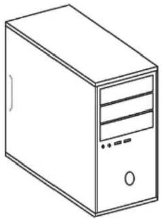
Chassis

DDR4 Memory
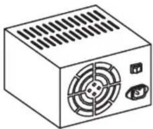
Power Supply Unit

Graphics Card

Thermal Paste
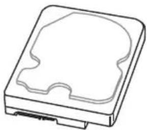
SATA Hard Disk Drive

SATA DVD Drive


A Package of Screws
Safety Information
- The components included in this package are prone to damage from electrostatic discharge (ESD). Please adhere to the following instructions to ensure successful computer assembly.
- Ensure that all components are securely connected. Loose connections may cause the computer to not recognize a component or fail to start.
- Hold the motherboard by the edges to avoid touching sensitive components.
- It is recommended to wear an electrostatic discharge (ESD) wrist strap when handling the motherboard to prevent electrostatic damage. If an ESD wrist strap is not available, discharge yourself of static electricity by touching another metal object before handling the motherboard.
- Store the motherboard in an electrostatic shielding container or on an anti-static pad whenever the motherboard is not installed.
- Before turning on the computer, ensure that there are no loose screws or metal components on the motherboard or anywhere within the computer case.
- Do not boot the computer before installation is completed. This could cause permanent damage to the components as well as injury to the user.
- If you need help during any installation step, please consult a certified computer technician.
- Always turn off the power supply and unplug the power cord from the power outlet before installing or removing any computer component.
- Keep this user guide for future reference.
- Keep this motherboard away from humidity.
- Make sure that your electrical outlet provides the same voltage as is indicated on the PSU, before connecting the PSU to the electrical outlet.
- Place the power cord such a way that people can not step on it. Do not place anything over the power cord.
• All cautions and warnings on the motherboard should be noted.
- If any of the following situations arises, get the motherboard checked by service personnel:
■ Liquid has penetrated into the computer. ■ The motherboard has been exposed to moisture.
- The motherboard does not work well or you can not get it work according to user guide.
■ The motherboard has been dropped and damaged. ■ The motherboard has obvious sign of breakage.
- Do not leave this motherboard in an environment above 60°C (140°F), it may damage the motherboard.
Installing a Processor![graph TD A["1: Cooling System"] --> B["2: Rotation"] B --> C["3: Cooling Unit"] C --> D["4: Cooling Body"] D --> E["5: Cooling Chamber"] E --> F["6: Rotation"] F --> G["7: Cooling System"] G --> H["8: Rotation"] H --> I["9: Cooling Component"] I --> J["10: Cooling Body"] J --> K["11: Cooling Turbine…](/content/2026/06/1350721/images/0350e6be246bf177a0f2e75e5feb944bafda0d5f6fc96492dc3742891d3a2e64.jpg)


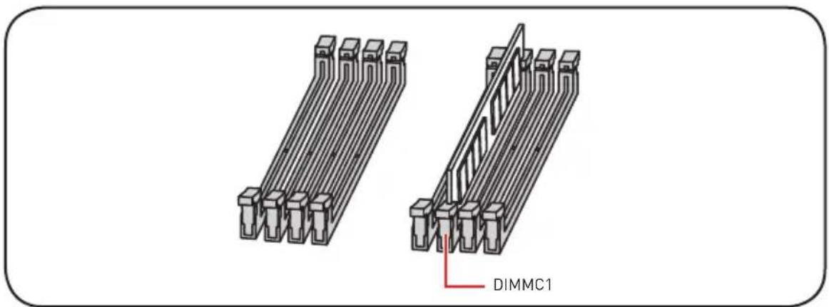
Installing DDR4 memory


http://youtu.be/T03aDrJPyQs
![graph TD A["Memory Card with Pin 1"] --> B["Inserted Block"] B --> C["Rotated Block with Arrow 2"] C --> D["Final Assembly with Pin 3"] style A fill:#f9f,stroke:#333 style B fill:#ccf,stroke:#333 style C fill:#cfc,stroke:#333 style D fill:#fcc,stroke:#333](/content/2026/06/1350721/images/7df9bdb77844ae47fea95b2e42f9545cdd60cc969886e42e70295e9ce6e985fe.jpg)
Connecting the Front Panel Header


http://youtu.be/DPELIdVNZUI

![graph LR A["+ - HDD LED"] --> B["HD- HDD LED"] C["+ - POWER LED"] --> D["HD- POWER LED"] E["+ - POWER LED"] --> F["HD- POWER LED +"]](/content/2026/06/1350721/images/81010ff1653f4e59d14679601ff924b39f06eb3728962e50d0b69b515b0bcb6f.jpg)
Installing the Motherboard

Installing SATA Drives


http://youtu.be/RZsMpqxythc


Installing a Graphics Card


http://youtu.be/mG0GZpr9w_A


Connecting Peripheral Devices
Connecting the Power Connectors


http://youtu.be/gkDYyR_83I4


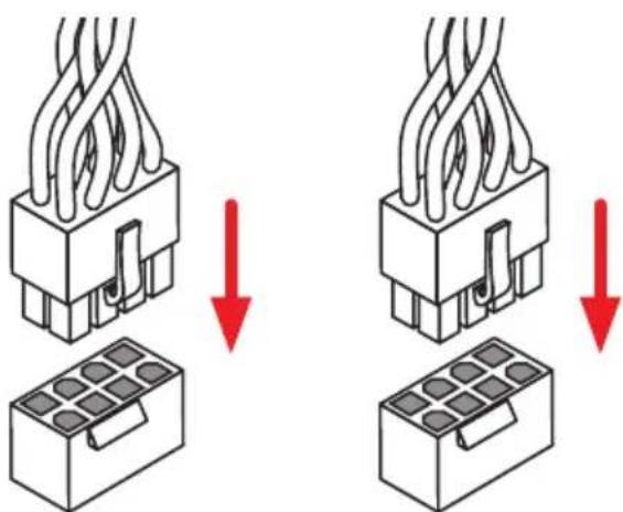
CPU_PWR1 CPU_PWR2


Power On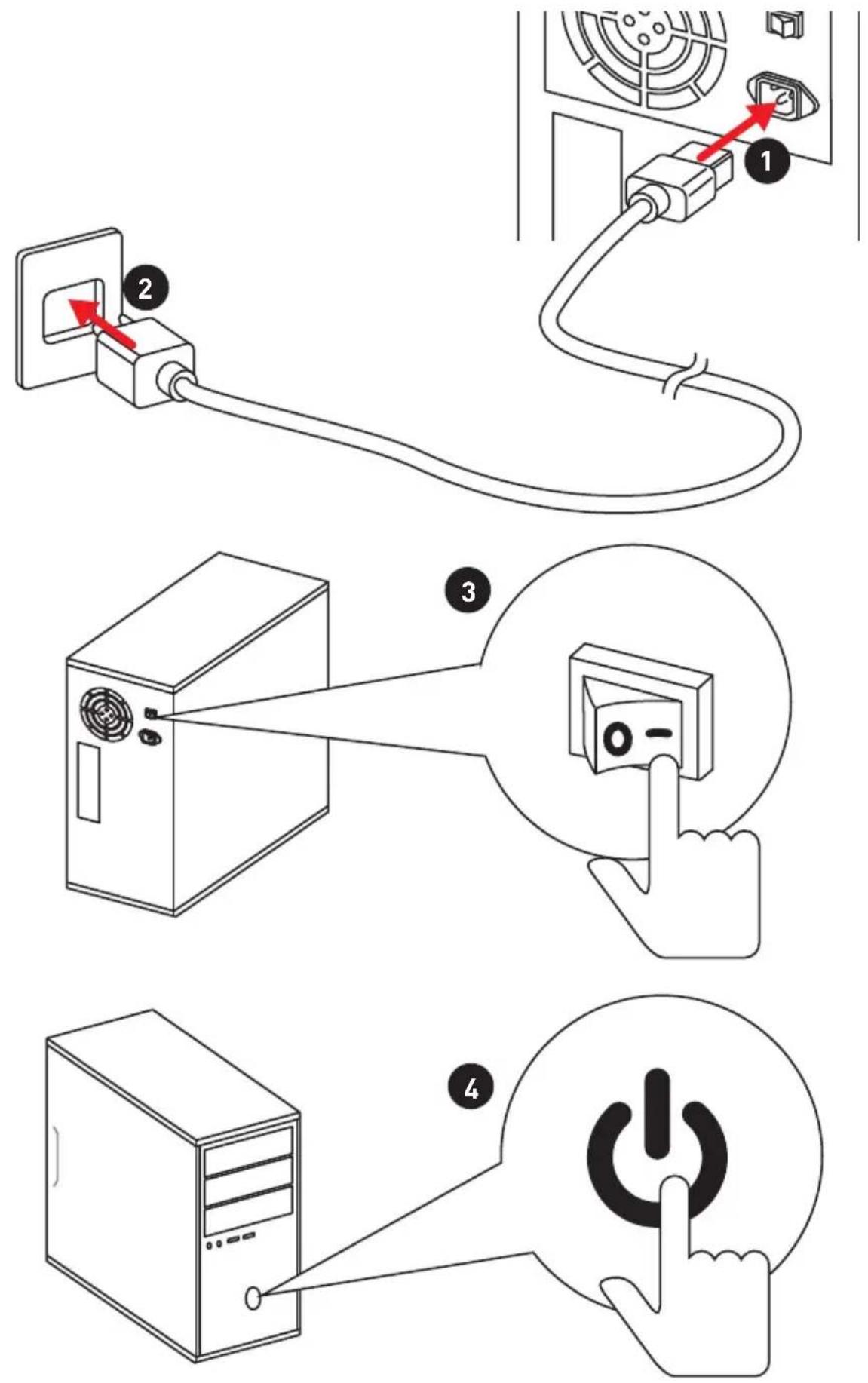
Contents
Quick Start .... 1
Preparing Tools and Components.... 1
Safety Information....2
Installing a Processor.... 3
Installing DDR4 memory 4
Connecting the Front Panel Header....5
Installing the Motherboard....6
Installing SATA Drives....7
Installing a Graphics Card 8
Connecting Peripheral Devices 9
Connecting the Power Connectors.... 10
Power On....11
Specifications.... 15
ThunderboltM3 Card Specification....21
JCORSAIR1 Connector Specification....21
Package contents.... 22
Block Diagram 23
Rear I/O Panel....24
2.5G LAN Port LED Status Table 24
1G LAN Port LED Status Table 24
Audio Ports Configuration 25
Realtek Audio Console 26
Installing Antennas.... 27
Overview of Components 28
CPU Socket 30
DIMM Slots....31
PCI_E1\~5: PCIe Expansion Slots 34
PCIe and M2_3 slot bandwidth table 34
U2_1: U.2 Connector....37
M2_1\~3: M.2 Slots (Key M) 38
Installing M.2 XPANDER-AERO Card 39
SATA1\~8: SATA 6Gb/s Connectors 41
VRAID1: Virtual RAID on CPU Connector 41
JFP1, JFP2: Front Panel Connectors 42
JAUD1: Front Audio Connector 42
CPU_PWR1\~3, ATX_PWR1, PCIE_PWR1: Power Connectors....43
OC1: GAME BOOST Knob 44
OC_RT1: OC Retry Jumper 46
OC_FS1: OC Force Enter BIOS Jumper 46
JSLOW1: Slow Mode Booting Jumper 46
CPU_FAN1, PUMP_FAN1, SYS_FAN1\~4, EXS_FAN1\~2: Fan Connectors ..... 47
W_FLOW1: Water Flow Meter Connector.... 48
T_SEN1: Thermal Sensor Connector 48
JTBT1: Thunderbolt Add-on Card Connector 48
Installing Thunderbolt M3 Card 49
JUSB3~4: USB 3.1 Gen1 Connectors .... 50
JUSB1~2: USB 2.0 Connectors....51
JUSB5: USB 3.1 Gen2 Type-C Connector....51
POWER1, RESET1: Power Button, Reset Button 52
JBAT1: Clear CMOS (Reset BIOS) Jumper 52
JCI1: Chassis Intrusion Connector.... 53
BIOS_SW1: Multi-BIOS Switch 54
JRGB1, JRAINBOW1~2: RGB LED connectors....55
JCORSAIR1: CORSAIR Connector 56
Onboard LEDs....57
EZ Debug LED 57
DIMM LEDs 57
XMP LED 57
Multi-BIOS LEDs....58
JPWRLED1: LED power input....58
Debug Code LED 59
Hexadecimal Character Table 59
Boot Phases....59
Debug Code LED Table 59
ACPI States Codes 64
CPU Temperature 64
Installing OS, Drivers & Utilities 65
Installing Windows 10....65
Installing Drivers 65
Installing Utilities 65
MYSTIC LIGHT 66
Device LED effect control screen 66
Nahimic 3....69
Installation and Update 69
Audio Tab 69
Microphone Tab 70
Sound Tracker Tab 71
Settings Tab 71
BIOS Setup 72
Entering BIOS Setup....72
Resetting BIOS....73
Updating BIOS....73
EZ Mode 75
Advanced Mode 77
SETTINGS....78
Advanced....78
Boot....84
Security 85
Save & Exit 86
OC....87
M-FLASH 94
OC PROFILE 95
HARDWARE MONITOR....96
RAID Configuration....97
Enabling Intel® Rapid Storage Technology....97
Creating RAID Volume 98
Removing a RAID Volume 99
Resetting Disks to Non-RAID 100
Rebuilding RAID Array.... 101
Installing RAID Driver....102
Installing Intel® Rapid Storage Technology Software 102
Intel® Optane™ Memory Configuration 103
System Requirements 103
Installing the Intel® Optane™ memory 103
Removing the Intel® Optane™ memory 105
Troubleshooting 106
Specifications
| CPU | Supports Intel® CoreTM X-Series Processor Family for LGA2066 Socket |
| Chipset Intel | ® X299 Chipset |
| Memory | 8x DDR4 memory slotsQuad channel memory architecture with the CPU that supports up to 4-channels DDR4**Quad channel support up to 128GBX-series processor support DDR4 4200(OC)/ 4100(OC)/ 4000(OC)/ 3800(OC)/ 3733(OC)/ 3600(OC)/ 3466(OC)/ 3400(OC)/ 3333(OC)/ 3200(OC)/ 3000(OC)/ 2933(OC)/ 2800(OC)/ 2666/ 2400/ 2133 MHz*Dual channel memory architecture with the CPU that supports up to 2-channels DDR4**Dual channel support up to 64GBX-series processor support DDR4 4133(OC)/ 4000(OC)/ 3866(OC)/ 3800(OC)/ 3733(OC)/ 3600(OC)/ 3466(OC)/ 3400(OC)/ 3333(OC)/ 3200(OC)/ 3000(OC)/ 2933(OC)/ 2800(OC)/ 2666/ 2400/ 2132 MHz*Supports IntExtreme Memory Profile (XMP)* Please refer www.msi.com for more information on compatible memory.** Please refer the DIMM Slots section for more details. |
| Expansion Slot | 4x PCIe 3.0 x16 slotsSupport x16/x0/x16/x8, x8/x8/x16/x8 mode with the 44-lane CPU.*Support x16/x0/x8/x4, x8/x8/x8/x4 mode with the 28-lane CPU.*Support x8/x0/x4/x4 mode with the 16-lane CPU.*1x PCIe 3.0 x1 slot* Please refer to page 34 for PCIe 3.0 bandwidth table. |
| Multi-GPU | Supports NVIDIA™ TechnologySupports AMDrossFire™ Technology |
| LAN | 1x Intel I219-V Gigabit LAN controller1x Realtek RTL8125-CG 2.5G LAN controller |
| Wirsless LAN & Bluetooth® | Intel® Wireless-AC 9260Supports 802.11 a/b/g/n/ac, MU-MIMO Rx, 2.4GHz/ 5GHz (160MHz) up to 1.73GbpsSupports Bluetooth®, 2.1+EDR, 3.0,4.0, 5 |
| Storage | Intel® X299 Chipset8x SATA 6Gb/s ports*3x M.2 slots (Key M)M2_1 & M2_2 support up to PCIe 3.0 x4 and SATA 6Gb 2242/ 2260/ 2280/ 22110 storage devicesM2_3 supports up to PCIe 3.0 x4, 2242/ 2260/ 2280 storage devices**Int©ptaneTM Memory Ready for M2_1, M2_2 slots ***1x U.2 portSupports PCIe 3.0 x4 NVMe storage* The SATA1 connector will be unavailable when a SATA M.2 SSD has been installed in the M.2_1 slot.* The SATA2 connector will be unavailable when a SATA M.2 SSD has been installed in the M.2_2 slot.** M2_3 slot and PCIe slots share the bandwidth. Please refer to page 34 for details.*** Before using Intel® OptaneTM memory modules, please ensure that you have updated the drivers and BIOS to the latest version from MSI website. |
| RAID | Intel® X299 ChipsetSupports RAID 0, RAID1, RAID 5 and RAID 10 for SATA storage devicesSupports RAID 0 and RAID 1 for M.2 PCIe storage devices |
| USB | Int©299 Chipset4x USB 3.1 Gen1 (SuperSpeed USB) ports available through the internal USB connectors6x USB 2.0 (High-speed USB) ports(2 ports on the back panel, 4 ports available through the internal USB connectors)ASMedASM3142 Chipset3x USB 3.1 Gen2 (SuperSpeed USB 10Gbps) ports (1 Type-C and 1 Type-A port on the back panel, 1 Type-C internal connector)ASMedASM1074 Chipset6x USB 3.1 Gen1 (SuperSpeed USB) ports on the back panel |
| Audio | 1x ReattellC1220 Codec7.1-Channel High Definition AudioSupports S/PDIF output |
| Back Panel Connectors | 1x BIOS FlashBack button1x Clear CMOS button1x PS/2 keyboard/ mouse combo port2x USB 2.0 Type-A ports6x USB 3.1 Gen1 Type-A ports1x 2.5G LAN (RJ45) port1x 1G LAN (RJ45) port1x USB 3.1 Gen2 Type-A port1x USB 3.1 Gen2 Type-C port2x Wi-Fi Antenna connectors5x OFC audio jacks1x Optical S/PDIF OUT connector |
| Internal Connectors | 1x 24-pin ATX main power connector3x 8-pin ATX 12V power connectors1x flat 4-pin ATX 12V power connector*8x SATA 6Gb/s connectors1x U.2 port2x USB 2.0 connectors (supports additional 4 USB 2.0 ports)2x USB 3.1 Gen1 connectors (supports additional 4 USB 3 Gen1 ports)1x USB 3.1 Gen2 Type-C port1x 4-pin CPU fan connector1x 4-pin Water Pump connector4x 4-pin system fan connectors2x 4-pin extend system fan connectors1x 3-pin Water Flow connector1x Front panel audio connector2x System panel connectors1x TPM module connector1x Chassis Intrusion connector1x 2-pin Thermal Sensors connector1x Virtual RAID on CPU connector1x Thunderbolt Add-on Card Connector* Provides additional power to PCIe x16 slots |
| LED Connectors | 1x 4-pin RGB LED connector2x 3-pin RAINBOW LED connectors1x 3-pin CORSAIR LED connector |
| OC Connectors | 1x OC retry connector1x OC force enter BIOS connector |
| Internal Buttons | 1x GAME BOOST knob1x Power button1x Reset button |
| Switches • 1x Multi-BIOS switch | |
| Jumper | 1x Slow mode jumper1x Clear CMOS jumper |
| Debug LED | 1x 2-Digit Debug Code LED4x EZ Debug LED |
| I/O Controller NUVOTON NCT6797 Controller Chip | |
| Hardware Monitor | CPU/System temperature detectionCPU/System fan speed detectionCPU/System fan speed control |
| Form Factor | E-ATX Form Factor12 in. x 10.7 in. (30.5 cm x 27.2 cm) |
| BIOS Features | Dual BIOS2x 128 Mb flashUEFI AMI BIOSACPI 6.1, SMBIOS 3.0Multi-language |
| Software | DriversDRAGON CENTERMYSTIC LIGHTNahimic AudioCPU-Z MSI GAMINGMSI App Player (BlueStacks)IntEktreme Tuning UtilityGoogle ChromeTM, Google Toolbar, Google DriveNortonTM Internet Security Solution | |
| Dragon Center Features | GAME OPTIMIZATIONOC PerformanceHardware MonitorEyerestLAN ManagerLive Update |  Please refer to http://download.msi.com/manual/mb/DRAGONCENTER2.pdf for more details. Please refer to http://download.msi.com/manual/mb/DRAGONCENTER2.pdf for more details. |
| Special Features | AudioAudio Boost 4Nahimic 3NetworkGAMING LAN with Gaming LAN ManagerDual LAN (2.5G+1G)Intel WiFiStorageTurbo U.23 x Turbo M.2FanPump FanSmart Fan ControlPerformanceMulti GPU - SLI TechnologyMulti GPU - CrossFire Technology | |
| Special Features | LEDMystic Light 3Mystic Light Extension (RGB)Mystic Light Extension (RAINBOW)Mystic Light Extension (CORSAIR)Mystic Light SyncEZ DEBUG LEDProtectionDDR4 Steel ArmorM.2 FORZRPCI-E Steel ArmorU.2 Steel ArmorDDR4 BoostGAME Boost(go to 11)OC Engine(Clock gen)Lightning USB(3142)Front Lightning USB(20PIN)Stability7000+ Quality TestVRVR ReadyGamer ExperienceGAMING HOTKEYGAMING MOUSE ControlBIOSClick BIOS 5BIOS FLASHBACK+Dual BIOSCertificationQuadro SLI ReadyQuadro ReadyGAMING Certified |
Thunderbolt 3 Card Specification
| Chipset Intel Thunderbolt 3 controller | |
| External connector | 2 x thunderbolt 3 port (type C)up to 40 Gbps for Thunderbolt devicesup to 10 Gbps for USB 3.1 devices1 x 5 pin TB header2 x DisplayPort input portsDisplayPort 1.2 specification |
| Interface PCIe 3.0 x4 (depends on MB supportive slot) | |
| Capabilities Supports | DisplayPort 1.2 with max, 4K x 2K @60/24 Hz |
| Form factor 3.35 inch x 4.11 inch (8.5 cm x 10.4 cm) | |
JCORSAIR1 Connector Specification
| Supporting CORSAIR RGB Products Maximum connection | |
| Lighting Node PRO LED Strip | 20** In the case of 20% brightness |
| HD120 RGB Fan 6 | |
| SP120 RGB Fan 6 | |
| LL120 RGB Fan 6 | |
Package contents
Please check the contents of your motherboard package. It should contain:
| Motherboard MEG X29 CREATION | ||
| Documentation | User Manual 1 | |
| Quick Installation Guide 1 | ||
| Application DVD Driver DVD 1 | ||
| Cable | SATA 6Gb/s Cables 4 | |
| 1 to 2 RGB LED Extension Y Cable 80cm 1 | ||
| CORSAIR RGB LED Extension Cable 50cm 1 | ||
| RAINBOW RGB LED Extension Cable 80cm 1 | ||
| Thermistor Cable 1 | ||
| Thunderbolt Cable 1 | ||
| Accessories | M.2 Xpander-AERO 1 | |
| SLI HB BRIDGE L 1 | ||
| ThunderboltM3 1 | ||
| Antenna Set | 1 | |
| Case Badge | 1 | |
| SATA cable Labels | 1 | |
| VIP Card | 1 | |
| IO Shielding | 1 | |
| M.2 Screw | 3 | |
Important
If any of the above items are damaged or missing, please contact your retailer.
Block Diagram
![graph TD A["Computer"] --> B["PCI Express Bus"] B --> C["SwitchSwitch"] C --> D["Processor"] D --> E["2/4 Channel DDR4 Memory"] D --> F["PCIe x1 slot"] D --> G["Wi-Fi / Bluetooth"] D --> H["Realtek 8125"] D --> I["Intel I219"] J["PCIE Bus"] --> K["X299 PCH"] L["PCIE Bus"] --> K M["ASMEDIA ASM3142"]…](/content/2026/06/1350721/images/e21e17dc71fca301a7e1eea4feaf892af9b319f2fbcee6f9d8b42305a59be75e.jpg)
Rear I/O Panel
- Clear CMOS button - Power off your computer. Press and hold the Clear CMOS button for about 5-10 seconds to reset BIOS to default values.
- BIOS FLASHBACK+ button/port - Please refer to page 74 for Updating BIOS with BIOS FLASHBACK+.
2.5G LAN Port LED Status Table![graph LR A["Link/ Activity LED"] --> B["Speed LED"] C["Status Description"] --> B D["Off No link"] --> B E["Yellow Linked"] --> B F["Blinking Data activity"] --> B B --> G["Off 10 Mbps connection"] B --> H["Green 1 Gbps/ 100 Mbps connection"] B --> I["Orange 2.5 Gbps connection"]](/content/2026/06/1350721/images/21f34ab6cf636f8092579677a7c8e6bf72ad89c5ead958e1b9d8814c4096d680.jpg)
1G LAN Port LED Status Table![graph LR A["Link/ Activity LED"] --> B["Speed LED"] C["Status Description"] --> A D["Off No link"] --> A E["Yellow Linked"] --> A F["Blinking Data activity"] --> A G["Off 10 Mbps connection"] --> A H["Green 100 Mbps connection"] --> A I["Orange 1 Gbps connection"] --> A](/content/2026/06/1350721/images/1d1372a740529e56e520a9d22ec592da8d507bcc4fbeaec80de0bb07b686a5a1.jpg)
Audio Ports Configuration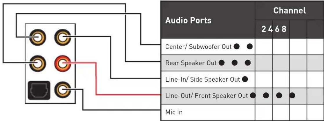
(●: connected, Blank: empty)
Audio jacks to headphone and microphone diagram
Audio jacks to 7.1-channel speakers diagram![graph TD A["Audio Input"] --> B["Rear Front"] B --> C["Side Center/Subwoofer"] C --> D["Output Module 1"] C --> E["Output Module 2"] C --> F["Output Module 3"] C --> G["Output Module 4"]](/content/2026/06/1350721/images/25bb05aac4ff93f30d50730fcfc67e2d58c18eeb4d4032c4a89a0ba8aebfe439.jpg)
Realtek Audio Console
After Realtek Audio Console is installed, you can use it to change sound settings to get a better sound experience.

- Device Selection - allows you to select an audio output source to change the related options. The check mark indicates the devices as default.
- Application Enhancement - the array of options will provide you complete guidance of anticipated sound effects for both output and input devices.
- Main Volume - controls the volume or balances the right/left side of the speakers that you plugged in front or rear panel by adjusting the bar.
- Advanced Settings - provides the mechanism to deal with 2 independent audio streams.
- Jack Status - depicts all render and capture devices currently connected with your computer.
- Connector Settings - configures the connection settings.
Auto popup dialog
When you plug into a device at an audio jack, a dialogue window will pop up asking you which device is currently connected.

Each jack corresponds to its default setting as shown on the next page.

The pictures above are for reference only and may vary from the product you purchased.
Installing Antennas
- Combine the antenna with the base.
- Screw two antenna cables tight to the WiFi antenna connectors as shown.
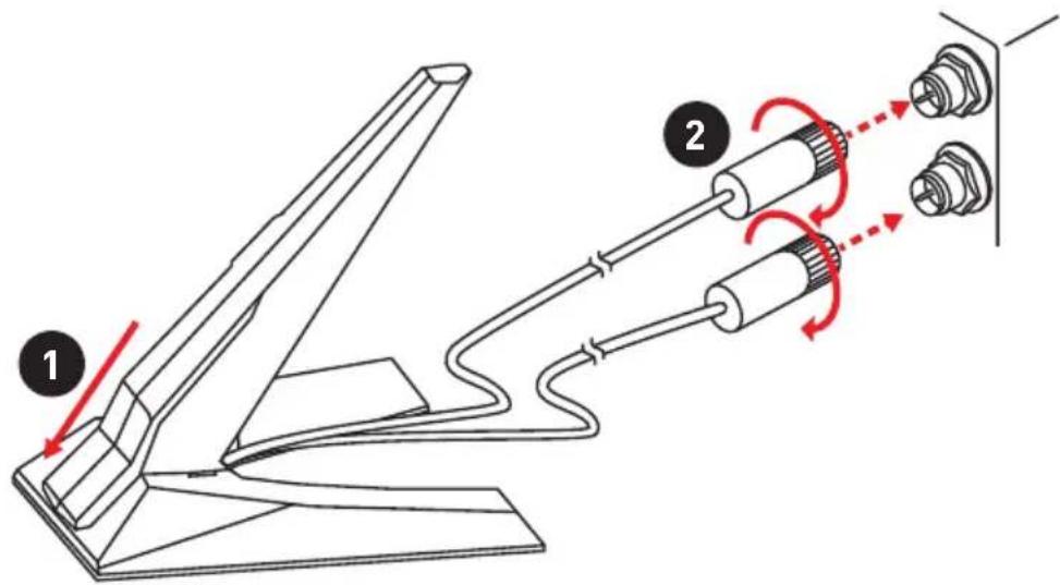
- Place the antenna as high as possible.

Overview of Components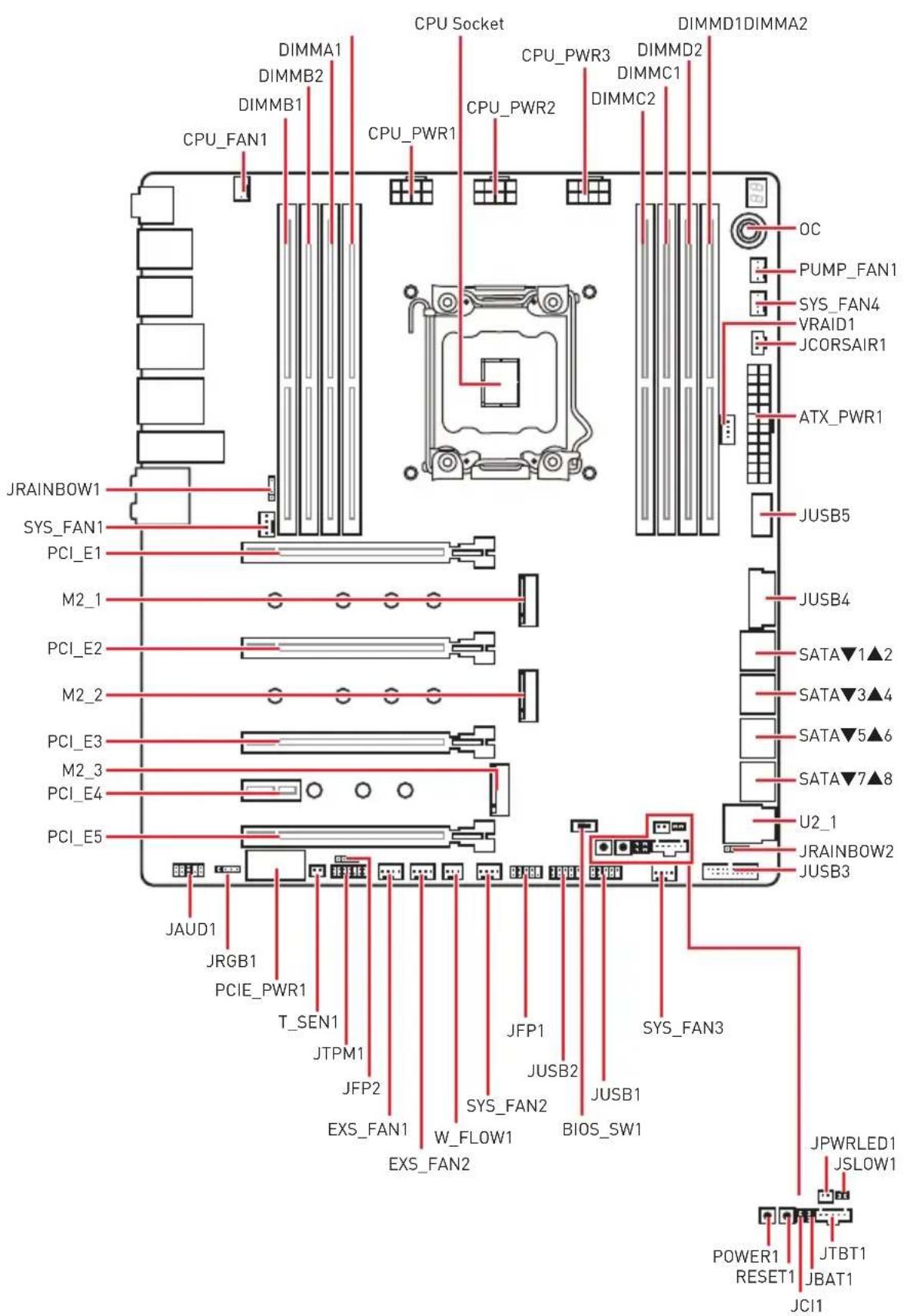
Component Contents
| Port Name Port Type Page | ||
| BIOS_SW1 Multi-BIOS Switch | 54 | |
| CPU_FAN1, PUMP_FAN1, SYS_FAN1~4, EXS_FAN1~2 | Fan Connectors 47 | |
| CPU_PWR1~3, ATX_PWR1, PCIE_PWR1 | Power Connectors 43 | |
| CPU Socket LGA2066 CPU Socket | 30 | |
| JAUD1 Front Audio Connector | 42 | |
| JBAT1 Clear CMOS (Reset B | OS) Jumper 52 | |
| JCI1 Chassis Intrusion Connector | 53 | |
| JCORSAIR1 | CORSAIR Connector | 56 |
| JFP1, JFP2 | Front Panel Connectors | 42 |
| JPWRLED1 | LED power input | 58 |
| JRGB1, JRAINBOW1~2 | RGB LED connectors | 55 |
| JSLOW1 | Slow Mode Booting Jumper | 46 |
| JTBT1 Thunderbolt Add-on Card | Connector 48 | |
| JUSB1~2 | USB 2.0 Connectors | 51 |
| JUSB3~4 | USB 3.1 Gen1 Connectors | 50 |
| JUSB5 USB 3.1 Gen2 Type-C | Connector 51 | |
| M2_1~3 | M.2 Slots (Key M) | 38 |
| OC1 | GAME BOOST Knob | 44 |
| OC_FS1 | OC Force Enter BIOS Jumper | 46 |
| OC_RT1 | OC Retry Jumper | 46 |
| PCI_E1~5 | PCIe Expansion Slots | 34 |
| POWER1, RESET1 | Power Button, Reset Button | 52 |
| SATA1~8 | SATA 6Gb/s Connectors | 41 |
| T_SEN1 | Thermal Sensor Connector | 48 |
| U2_1 | U.2 Connector | 37 |
| VRAID1 | Virtual RAID on CPU Connector | 41 |
| W_FLOW1 | Water Flow Meter Connector | 48 |
CPU Socket
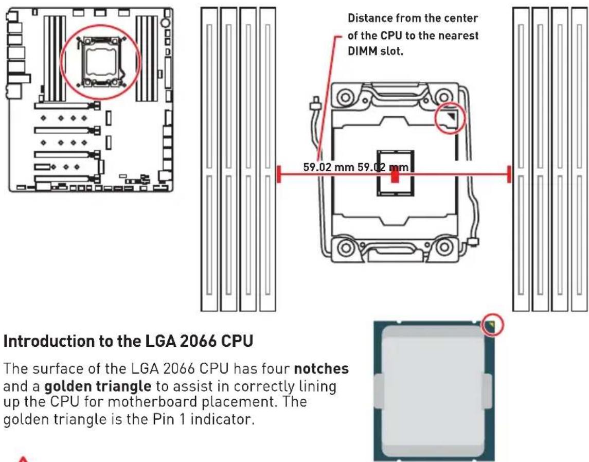
Important
Always unplug the power cord from the power outlet before installing or removing the CPU.
Please retain the CPU protective cap after installing the processor. MSI will deal with Return Merchandise Authorization (RMA) requests if only the motherboard comes with the protective cap on the CPU socket.
When installing a CPU, always remember to install a CPU heatsink. A CPU heatsink is necessary to prevent overheating and maintain system stability.
Confirm that the CPU heatsink has formed a tight seal with the CPU before booting your system.
Overheating can seriously damage the CPU and motherboard. Always make sure the cooling fans work properly to protect the CPU from overheating. Be sure to apply an even layer of thermal paste (or thermal tape) between the CPU and the heatsink to enhance heat dissipation.
Whenever the CPU is not installed, always protect the CPU socket pins by covering the socket with the plastic cap.
If you purchased a separate CPU and heatsink/ cooler, Please refer to the documentation in the heatsink/ cooler package for more details about installation.
This motherboard is designed to support overclocking. Before attempting to overclock, please make sure that all other system components can tolerate overclocking. Any attempt to operate beyond product specifications is not recommended. MSI® does not guarantee the damages or risks caused by inadequate operation beyond product specifications.
DIMM Slots
S/K LED : S/K LED indicates that the installed CPU supports either 4-channels or 2-channels memory architecture.
Red = 8 DIMMs support (4-channels architecture CPU)
White = 4 DIMMs support (2-channels architecture CPU)
Memory module installation recommendation (4-Channels architecture CPU)
| B1 | B2 | A1 | A2 | Intel Core X-series CPU C2 C1 D2 D1 | |||||
| 1 DIMM | ✓ | ||||||||
| 2 DIMMs | ✓ | Supports 4-channelsmemory architecture | ✓ | ||||||
| 3 DIMMs | ✓ | ✓ | ✓ | ||||||
| 4 DIMMs | ✓ | ✓ | ✓ | ✓ | |||||
| 5 DIMMs | ✓ | ✓ | ✓ | ✓ | ✓ | ||||
| 6 DIMMs | ✓ | ✓ | ✓ | ✓ | ✓ | ✓ | |||
| 7 DIMMs | ✓ | ✓ | ✓ | ✓ | ✓ | ✓ | ✓ | ||
| 8 DIMMs | ✓ | ✓ | ✓ | ✓ | ✓ | ✓ | ✓ | ✓ |

Important
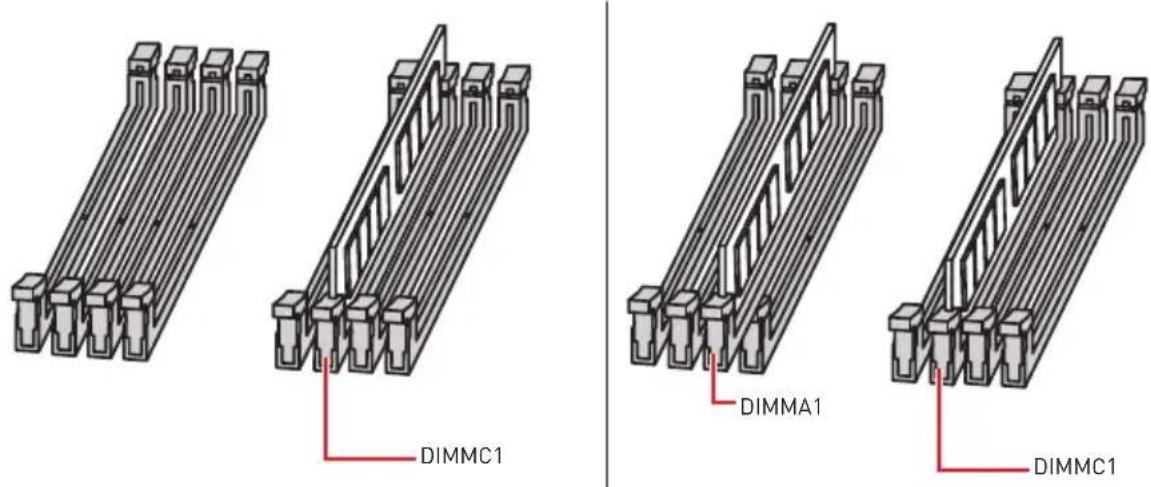
Always insert a memory module in the DIMMC1 slot first.
To ensure system stability for Dual/ Triple/ Quad channel mode, memory modules must be of the same type, number and density. And for every channel, the odd number DIMM slot must be installed first.
Due to chipset resource usage, the available capacity of memory will be a little less than the amount of installed.
Based on Intel CPU specification, the Memory DIMM voltage below 1.35V is suggested to protect the CPU.
Please note that the maximum capacity of addressable memory is 4GB or less for 32-bit Windows OS due to the memory address limitation. Therefore, we recommended that you to install 64-bit Windows OS if you want to install more than 4GB memory on the motherboard.
It is recommended to use a more efficient memory cooling system for full DIMMs installation or overclocking.
The stability and compatibility of installed memory modules depend on installed CPU and devices when overclocking.
Memory module installation recommendation (2-Channels architecture CPU)
| B1 | B2 | A1 | A2 | Intel Core | X-series | CPU | C2 | C1 | D2 | D1 | |||||
| 1 DIMM |  | Supports 2-channelsmemory architecture | ✓ | ||||||||||||
| 2 DIMMs | ✓ | ✓ | |||||||||||||
| 3 DIMMs | ✓ | ✓ | ✓ | ||||||||||||
| 4 DIMMs | ✓ | ✓ | ✓ | ✓ | |||||||||||
DIMMB1, B2, A1 and A2 are un-available

PCI_E1\~5: PCIe Expansion Slots
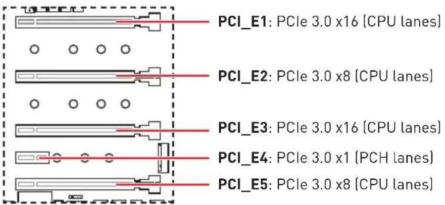
PCIe and M2_3 slot bandwidth table
for 44-lane CPU
| Graphics Card 2-Way 2-Way 2-Way* 3-Way 3-Way* 4-Way* | |||
| PCI_E1 @ 3.0 x8 @ 3.0 x16 @ 3.0 x16 @ 3.0 x8 @ 3.0 x16 @ 3.0 x8 | |||
| PCI_E2 @ 3.0 x8 Empty Empty @ 3.0 x8 Empty @ 3.0 x8 | |||
| PCI_E3 Empty Empty @ 3.0 x16 @ 3.0 x16 @ 3.0 x16 @ 3.0 x16 | |||
| PCI_E5 Empty @ 3.0 x8 Empty Empty @ 3.0 x8 @ 3.0 x8 | |||
| M2_3 3.0 x4 3.0 x4 3.0 x4 3.0 x4 3.0 x4 3.0 x4 |
(@: graphics card slot, *: best combination)
for 28-lane CPU
| Graphics Card 2-Way 2-Way* 3-Way 3-Way 3-Way* 4-Way* | ||||||
| PCI_E1 @ 3.0 x8 @ 3.0 x16 @ | 3.0 x8 @ 3.0 x16 @ | 3.0 x8 @ 3.0 x16 @ | 3.0 x8 @ 3.0 x8 | |||
| PCI_E2 @ 3.0 x8 Empty @ 3.0 | x8 Empty @ 3.0 x8 @ 3.0 x8 | |||||
| PCI_E3 Empty @ 3.0 x8 Empty @ 3.0 x8 @ 3.0 x8 | ||||||
| PCI_E5 | — | — | @ 3.0 x4 | @ 3.0 x4 | — | @ 3.0 x4 |
| M2_3 | 3.0 x4 | 3.0 x4 | — | — | 3.0 x4 | — |
(@: graphics card slot, —: unavailable, *: best combination)
for 16-lane CPU
| Graphics Card | 2-Way | 3-Way |
| PCI_E1 | @ 3.0 x8 | @ 3.0 x8 |
| PCI_E2 | — | — |
| PCI_E3 | @ 3.0 x4 | @ 3.0 x4 |
| PCI_E5 | — | @ 3.0 x4 |
| M2_3 | 3.0 x4 | — |
(@: graphics card slot, —: unavailable, *: best combination)
Multiple graphics cards installation recommendation


Important
If you install a large and heavy graphics card, you need to use a tool such as MSI Gaming Series Graphics Card Bolster to support its weight and to prevent deformation of the slot.
Important
For a single PCIe x16 expansion card installation with optimum performance, using the PCI_E1 slot is recommended.
When adding or removing expansion cards, always turn off the power supply and unplug the power supply power cable from the power outlet. Read the expansion card's documentation to check for any necessary additional hardware or software changes.
Installing SLI graphics cards
For power supply recommendations for SLI configurations, please refer to the user guide of your graphics card to make sure you meet all the system requirements.
To install SLI graphics cards:
- Turn off your computer and disconnect the power cord, install two graphics cards into the PCI_E1 and PCI_E3 slots.
- Connect the two cards together using the SLI Bridge Connector.

- Connect all PCIe power connectors of the graphics cards.
- Reconnect the power cord, power up the computer and install the drivers and software included in your graphics card package.
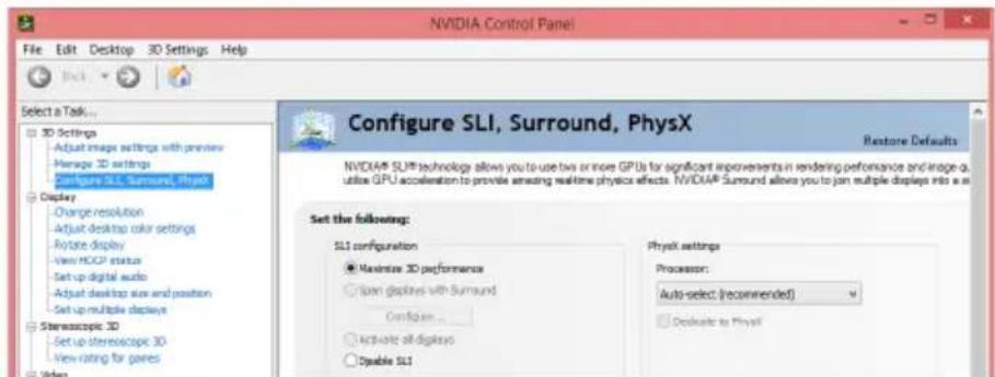
- Right-click the Windows desktop and select NVIDIA Control Panel from the menu, click on Configure SLI, Surround, PhysX in the left task pane and select Maximize 3D performance in the SLI configuration menu, and then click Apply.
U2_1: U.2 Connector
This connector is a U.2 interface port. Each connector can connect to one PCIe 3.0 x4 NVMe storage device.



Video Demonstration
Watch the video to learn how to Install U.2 SSD. http://youtu.be/KgFvKDxymvw
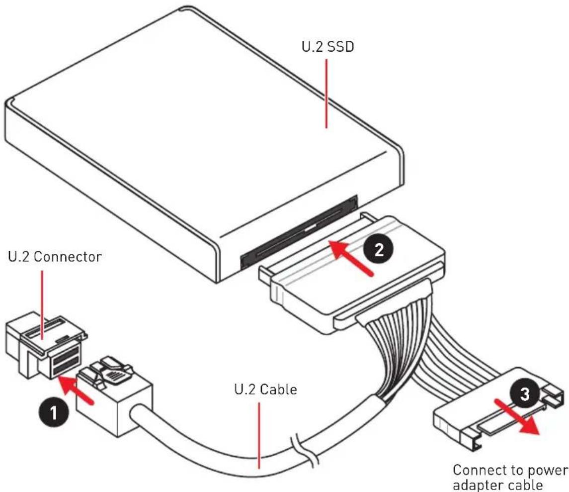
Installing U.2 SSD
- Connect the U.2 cable to the U.2 connector on the motherboard.
- Connect the U.2 cable to the U.2 SSD.
- Connect the U.2 cable to the power adapter cable.

Important
The M2_2, SATA5, and SATA6 will be unavailable when installing a U.2 device into the U.2 port.
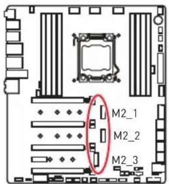
M2_1~3: M.2 Slots (Key M)
Important
Intel® RST only supports PCIe M.2 SSD with UEFI ROM.
Intel® Optane™ Memory Ready for M2_1, M2_2 slots.
M2_3 slot only supports PCIe 3.0 interface.
Installing M.2 module
- Remove the screw from the base screw.
- Remove the base screw.
- Tighten the base screw into the hole of the distance to the M.2 slot as the length of your M.2 module.
- Insert your M.2 module into the M.2 slot at a 30-degree angle.
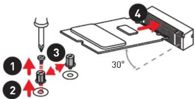
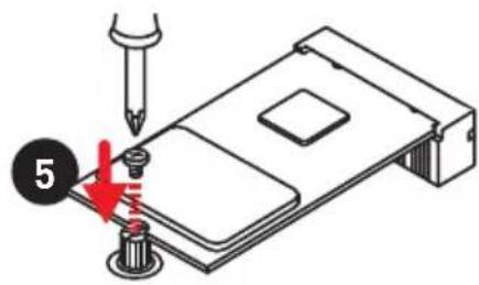
- Put the screw in the notch on the trailing edge of your M.2 module and tighten it into the base screw.
Using M.2 Shield Frozr
We provide the M.2 Shield Frozr on the M2_2 slot to help dissipate heat away from the M.2 module. Before installing the M.2 module, you need to remove screws that secure the M.2 Shield Frozr, lift the M.2 Shield Frozr and remove the protective film and the rubber from the thermal pad.
![graph TD A["Tool"] --> B{Flow Direction} B -->|Red Arrow| C["Component 1"] B -->|Red Arrow| D["Component 2"] B -->|Red Arrow| E["Component 3"] C --> F["Final Component"] D --> F E --> F](/content/2026/06/1350721/images/3206d17ffc627e4ea72d63eb3b340b41af1c327a335d8c269835f78fef68f582.jpg)
Installing M.2 XPANDER-AERO Card
The M.2 XPANDER-AERO card provides four M.2 Key-M slots.
To install the M.2 XPANDER-AERO card:
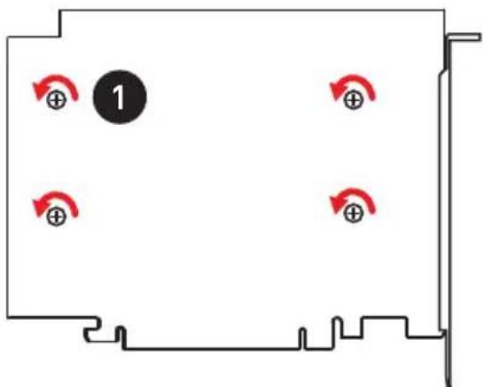
- Remove the heatsink by loosening four heatsink screws on the bottom of M.2 XPANDER-AERO.
- Remove the screw from the base screw.
- Remove the base screw.
- Tighten the base screw into the hole of the distance to the M.2 slot as the length of your M.2 device.
- Insert your M.2 device into the M.2 slot at a 30-degree angle.
- Put the screw in the notch on the trailing edge of your M.2 device and tighten it into the base screw.

- Remove the protective film from the thermal pad of the heatsink.
- Reinstall the heatsink by tightening four heatsink screws on the bottom of M.2 XPENDER-AERO.


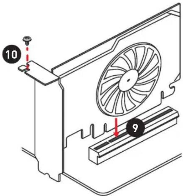
- Insert the M.2 XPENDER-AERO into an PCIe x16 slot.
- Use the screw to secure the M.2 XPENDER-AERO.
- Connect the PCIE_PWR1 connector to the power supply.
- Connect the case's HDD LED cable to the JCASE connector.
- Using the supplied HDD LED cable to connect the JMB connector and HDD LED pins (pin 1 & pin3) of JFP1.

SATA1\~8: SATA 6Gb/s Connectors
These connectors are SATA 6Gb/s interface ports. Each connector can connect to one SATA device.

Important
The SATA1 connector will be unavailable when a SATA M.2 SSD has been installed in the M.2_1 slot.
The SATA2 connector will be unavailable when a SATA M.2 SSD has been installed in the M.2_2 slot.
Please do not fold the SATA cable at a 90-degree angle. Data loss may result during transmission otherwise.
SATA cables have identical plugs on either sides of the cable. However, it is recommended that the flat connector be connected to the motherboard for space saving purposes.
VRAID1: Virtual RAID on CPU Connector
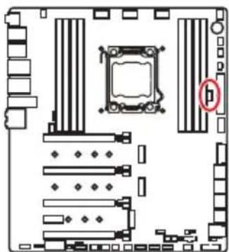
This connector allows you to connect the VROC (Virtual RAID on CPU) key module. You need to enable the VROC function with Intel® RSTe (Intel® Rapid Storage Technology enterprise) driver.
| 1 | |||
| 1 G | ND 2 VCC3 | ||
| 3 G | ND 4 SATA_RAID_KEY | ||
Important
The VROC key module is purchased separately.
JFP1, JFP2: Front Panel Connectors
These connectors connect to the switches and LEDs on the front panel.


JFP2 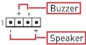 | 1 Speaker - 2 Buzzer + | |||
| 3 Buzzer - 4 | Speaker + | |||
JAUD1: Front Audio Connector
This connector allows you to connect audio jacks on the front panel.

 | |||
| 1 | MIC L | 2 | Ground |
| 3 | MIC R | 4 | NC |
| 5 | Head Phone R | 6 | MIC Detection |
| 7 | SENSE_SEND | 8 | No Pin |
| 9 | Head Phone L | 10 | Head Phone Detection |
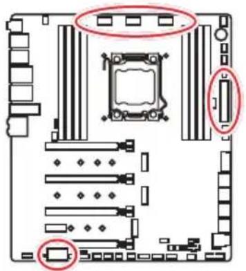
CPU_PWR1\~3, ATX_PWR1, PCIE_PWR1: Power Connectors
These connectors allow you to connect an ATX power supply.
| 8 5 CPU_PWR1~34 1 | |||
| 1 Ground 5 | +12V | ||
| 2 Ground 6 | +12V | ||
| 3 Ground 7 | +12V | ||
| 4 Ground 8 | +12V | ||
| 12 24ATX_PWR11 13 | 1 +3.3V 13 +3.3V | ||
| 2 +3.3V 14 -12V | |||
| 3 Ground 15 Ground | |||
| 4 +5V 16 PS-ON# | |||
| 5 Ground 17 Ground | |||
| 6 +5V 18 Ground | |||
| 7 Ground 19 Ground | |||
| 8 PWR OK 20 Res | |||
| 9 5VSB 21 +5V | |||
| 10 +12V 22 +5V | |||
| 11 +12V 23 +5V | |||
| 12 +3.3V 24 Ground |
| PCIE_PWR11 | 1+1 | 2V 3 Ground | ||
| 2 Ground | 4 | +5V |
Important
Make sure that all the power cables are securely connected to a proper ATX power supply to ensure stable operation of the motherboard.
OC1: GAME BOOST Knob
This knob allows you to manually select a stage from number 0 (default) to number 11 (extreme) for overclocking the processor. The processor's voltage and frequency will be automatically adjusted after you power on your computer.


Using GAME BOOST Knob
To setup the GAME BOOST knob, take the following steps:
- Set the GAME BOOST knob to hardware mode in BIOS Setup.
- Power off the computer.
- Refer to GAME BOOST Knob overclocking stage table and rotate the GAME BOOST knob to select the overclocking stage as you desire.
- Power on and then GAME BOOST will automatically overclock processor depending on the stage you selected.
To disable GAME BOOST:
- Set the GAME BOOST knob to HW mode in BIOS Setup.
- Power off the computer.
- Rotate the GAME BOOST knob to 0 and then power on. The configuration parameters will be returned to default values.

Important
When enabling GAME BOOST mode, it is recommended to use liquid CPU cooler with dual fan radiator for better cooling and performance.
You can also control the GAME BOOST function in BIOS Setup or with MSI DRAGON CENTER software.
In order to optimize performance and improve system stability, when you activate the GAME BOOST function, please leave the settings in the BIOS > OC menu unchanged.
The success of overclocking depends on the components of your computer.
We do not guarantee the GAME BOOST overclocking range or the damages/risks caused by overclocking behavior.
MSI components are recommended for better compatibility when using GAME BOOST function.
GAME BOOST Knob overclocking stage table
| Stage | CPU Max Frequency | |||||
| i5-7640X i7-7740X i7-7800X i7-7820X i7-9800X i9-7900X | ||||||
| 0 4.0 | GHz 4.3 GHz 3.5 GHz 3.6 GHz 3.8 GHz 3.3 GHz | |||||
| 1 4.5 | GHz 4.8 GHz 4.1 GHz 4.4 GHz 4.5 GHz 4.4 GHz | |||||
| 2 4.6 | GHz 4.9 GHz 4.2 GHz 4.5 GHz 4.6 GHz 4.5 GHz | |||||
| 4 | 4.7 GHz | 5.0 GHz | 4.3 GHz | 4.6 GHz | 4.7 GHz | 4.6 GHz |
| 6 | 4.8 GHz | 5.1 GHz | 4.4 GHz | 4.7 GHz | 4.8 GHz | 4.7 GHz |
| 8 | 4.9 GHz | 5.2 GHz | 4.5 GHz | 4.8 GHz | 4.9 GHz | 4.8 GHz |
| 10 | 5.0 GHz | 5.3 GHz | 4.6 GHz | 4.9 GHz | 5.0 GHz | 4.9 GHz |
| 11 | 5.1 GHz | 5.4 GHz | 4.7 GHz | 5.0 GHz | 5.1 GHz | 5.0 GHz |
| Stage | CPU Max Frequency | ||||
| i9-7920X i9-7940X i9-7960X i9-7980XE i9-9820X | |||||
| 0 | 2.9 GHz | 3.1 GHz | 2.8 GHz | 2.6 GHz | 3.3 GHz |
| 1 4.4 | GHz 4.4 GHz 4.3 | GHz 4.3 GHz 4.2 | GHz | ||
| 2 4.5 | GHz 4.5 GHz 4.4 | GHz 4.4 GHz 4.3 | GHz | ||
| 4 4.6 | GHz 4.6 GHz 4.5 | GHz 4.5 GHz 4.4 | GHz | ||
| 6 | 4.7 GHz | 4.7 GHz | 4.6 GHz | 4.6 GHz | 4.5 GHz |
| 8 | 4.8 GHz | 4.8 GHz | 4.7 GHz | 4.7 GHz | 4.6 GHz |
| 10 | 4.9 GHz | 4.9 GHz | 4.8 GHz | 4.8 GHz | 4.7 GHz |
| 11 | 5.0 GHz | 5.0 GHz | 4.9 GHz | 4.9 GHz | 4.8 GHz |
| Stage | CPU Max Frequency | ||||
| i9-9900X i9-9920X i9-9940X i9-9960X i9-9980XE | |||||
| 0 | 3.5 GHz | 3.5 GHz | 3.3 GHz | 3.1 GHz | 3.0 GHz |
| 1 4.5 | GHz 4.5 GHz 4.5 | GHz 4.5 GHz 4.5 | GHz | ||
| 2 4.6 | GHz 4.6 GHz 4.6 | GHz 4.6 GHz 4.6 | GHz | ||
| 4 | 4.7 GHz | 4.7 GHz | 4.7 GHz | 4.7 GHz | 4.7 GHz |
| 6 4.8 | GHz 4.8 GHz 4.8 | GHz 4.8 GHz 4.8 | GHz | ||
| 8 | 4.9 GHz | 4.9 GHz | 4.9 GHz | 4.9 GHz | 4.9 GHz |
| 10 | 5.0 GHz 5.0 | GHz 5.0 GHz 5.0 | GHz 5.0 GHz | ||
| 11 | 5.1 GHz | 5.1 GHz | 5.1 GHz | 5.1 GHz | 5.1 GHz |
OC_RT1: OC Retry Jumper
When you close this jumper, the system will keep retrying OC items until it boots up successfully.
OC_FS1: OC Force Enter BIOS Jumper
When you close this jumper, the system will be forced to access the BIOS and skip OC failure messages.

JSLOW1: Slow Mode Booting Jumper
This jumper is used for LN2 cooling solution, which provides extreme overclocking conditions, to boot at a stable processor frequency and to prevent the system from crashing.

Important
Users will try extreme low temperature overclocking at their own risk. The overclocking results will vary according to the CPU version.
Please don't switch to Enabled when power-off or the system will be un-bootable.
CPU_FAN1, PUMP_FAN1, SYS_FAN1~4, EXS_FAN1~2: Fan Connectors
Fan connectors can be classified as PWM (Pulse Width Modulation) Mode or DC Mode. PWM Mode fan connectors provide constant 12V output and adjust fan speed with speed control signal. DC Mode fan connectors control fan speed by changing voltage. This motherboard can automatically detect PWM and DC mode. However, you can follow the instruction below to adjust the fan connector to PWM or DC Mode manually.


CPU_FAN1/ PUMP_FAN1/ SYS_FAN1/ SYS_FAN4

SYS_FAN2/ SYS_FAN3 EXS_FAN1/ EXS_FAN2
You can switch between PWM mode and DC mode and adjust fan speed in BIOS > HARDWARE MONITOR.
Select PWM mode or DC mode

There are gradient points of the fan speed that allow you to adjust fan speed in relation to CPU temperature.

Important
Make sure fans are working properly after switching the PWM/ DC mode.
Pin definition of fan connectors
| PWM Mode pin definition | |||
| 1 G | round 2 +12V | ||
| 3 S | Sense 4 Speed | Control | Signal |
| DC Mode pin definition | |||
| 1 G | round 2 Voltage | Control | |
| 3 S | Sense 4 NC | ||
W_FLOW1: Water Flow Meter Connector
This connector allows you to connect a water flow meter to monitor the flow rate of your liquid cooling system.

| 1 | |||
| 1 Ground 3 WFLOW IN | |||
| 2 WFLOW PWR | |||
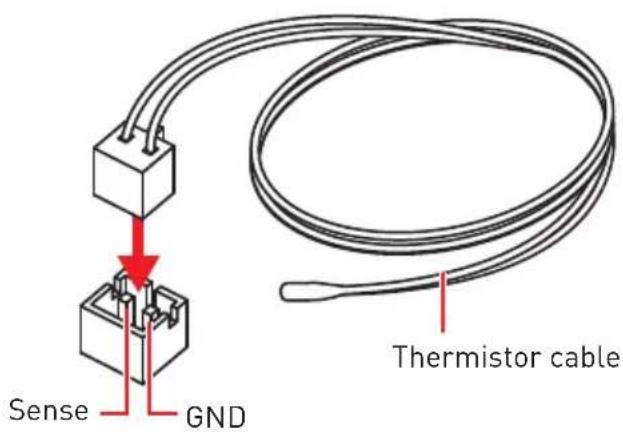
T_SEN1: Thermal Sensor Connector
This connector allows you to connect the thermistor cable and use it to monitor the temperature of the detection point.

JTBT1: Thunderbolt Add-on Card Connector
This connector allows you to connect the add-on Thunderbolt I/O card.

 | |||
| 1 FORCE_PWR 2 SCI_EVENT | |||
| 3 SLP_S3# 4 SLP_S5# | |||
| 5 GND | |||
Installing ThunderboltM3 Card
- Insert the ThunderboltM3 into the PCIe 3.0 x4 Thunderbolt supportive slot.
- Connect one end of the Thunderbolt cable to the J1 connector on the card.
- Connect the other end of the Thunderbolt cable to the JTBT1 connector on the motherboard.
- Use the screw to secure the ThunderboltM3.
- Connect one end of the DisplayPort cable to DP IN port on the ThunderboltM3.
- Connect the other end of the DisplayPort cable to DP port on the graphics card.
- Enabling Thunderbolt Technology in the BIOS.

Daisy-Chain Thunderbolt drives and DisplayPort monitor![graph LR A["Computer"] --> B["Device 1"] B --> C["Device 2"] C --> D["Device 3"] D --> E["Device 4"] E --> F["Device 5"] F --> G["Device 6"] G --> H["Device 7"] style A fill:#f9f,stroke:#333 style H fill:#bbf,stroke:#333 note bottom Daisy-Chain up to six Thunderbolt devices](/content/2026/06/1350721/images/15a003f10469f0018809b052cb9c799097397d1a78172a82e1ce76b99cde12f3.jpg)
JUSB3~4: USB 3.1 Gen1 Connectors
These connectors allow you to connect USB 3.1 Gen1 ports on the front panel.

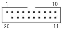 JUSB3 JUSB3 | 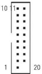 JUSB4 JUSB4 | ||
| 1 Power 11 USB2.0+ | |||
| 2 USB3_RX_DN 12 USB2.0- | |||
| 3 USB3_RX_DP 13 Ground | |||
| 4 Ground 14 | USB3_TX_C_DP | ||
| 5 | USB3_TX_C_DN | 15 | USB3_TX_C_DN |
| 6 | USB3_TX_C_DP | 16 Ground | |
| 7 Ground 17 | USB3_RX_DP | ||
| 8 | USB2.0- | 18 | USB3_RX_DN |
| 9 | USB2.0+ | 19 | Power |
| 10 | NC | 20 | No Pin |
Important
Note that the Power and Ground pins must be connected correctly to avoid possible damage.
Charger Port
The JUSB4 connector is a charger port which can increase USB power output for fast charging your smartphone or USB-powered devices. The Charger Port is hardware controlled by motherboard chip, it can still charge your device in suspend, hibernate state or even shutdown states. However, when you boot the computer into Windows, you will need to install the MSI DRAGON CENTER software to turn ON/OFF the Charging mode.
Important
When the Charging mode is enabled, the Charger Port data syncing will be disabled.
JUSB1~2: USB 2.0 Connectors

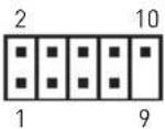 | |||
| 1 VCC 2 VCC | |||
| 3 USB0- 4 USB1- | |||
| 5 USB0+ 6 USB1+ | |||
| 7 Ground 8 Ground | |||
| 9 No Pin 10 NC | |||

Important
Note that the VCC and Ground pins must be connected correctly to avoid possible damage.
In order to recharge your iPad, iPhone and iPod through USB ports, please install MSI DRAGON CENTER utility.
JUSB5: USB 3.1 Gen2 Type-C Connector
This connector allows you to connect USB 3.1 Gen2 Type-C connector on the front panel. The connector possesses a foolproof design. When you connect the cable, be sure to connect it with the corresponding orientation.

POWER1, RESET1: Power Button, Reset Button
The Power / Reset button allows you to power on / reset the computer.



Power button Reset button
JBAT1: Clear CMOS (Reset BIOS) Jumper
There is CMOS memory onboard that is external powered from a battery located on the motherboard to save system configuration data. If you want to clear the system configuration, set the jumper to clear the CMOS memory.
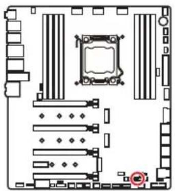

Keep Data (default)

Clear CMOS/Reset BIOS
Resetting BIOS to default values
- Power off the computer and unplug the power cord
- Use a jumper cap to short JBAT1 for about 5-10 seconds.
- Remove the jumper cap from JBAT1.
- Plug the power cord and power on the computer.
JCI1: Chassis Intrusion Connector
This connector allows you to connect the chassis intrusion switch cable.


Normal (default)

Trigger the chassis intrusion event
Using chassis intrusion detector
- Connect the JCI1 connector to the chassis intrusion switch/ sensor on the chassis.
- Close the chassis cover.
- Go to BIOS > SETTINGS > Security > Chassis Intrusion Configuration.
- Set Chassis Intrusion to Enabled.
- Press F10 to save and exit and then press the Enter key to select Yes.
- Once the chassis cover is opened again, a warning message will be displayed on screen when the computer is turned on.
Resetting the chassis intrusion warning
- Go to BIOS > SETTINGS > Security > Chassis Intrusion Configuration.
- Set Chassis Intrusion to Reset.
- Press F10 to save and exit and then press the Enter key to select Yes.
BIOS_SW1: Multi-BIOS Switch
This motherboard has two built-in BIOS ROMs. If one is crashed, you can shift to the other for booting by sliding the switch.


Recovering BIOS
When BIOS updating fails or causes the computer non-bootable, you can recover the failed BIOS by the steps below. Before recovering, please download the latest BIOS file that matches your motherboard model from MSI website. And then save the BIOS file to the root of the USB flash drive.
- Power off the computer.
- Switch to the normal BIOS ROM with Multi-BIOS switch.
- Insert the USB flash drive into the computer.
- Power on the computer and press Del key to enter BIOS setup during POST.
- Select the M-FLASH tab and click on Yes to reboot the system and enter the flash mode.
- Select a BIOS file to perform the BIOS recovering process.
- Switch to the failed BIOS ROM with the Multi-BIOS switch, and click Yes to start recovering the BIOS.
- After the recovery process is completed, the system will reboot automatically.

Do not use the Multi-BIOS switch while the system is booting up.
You can also use the LIVE UPDATE or BIOS FLASHBACK+ utility to flash the BIOS. Please refer to the BIOS section for details.
JRGB1, JRAINBOW1~2: RGB LED connectors
The JRGB connector allows you to connect 5050 RGB LED strips (12V). The JRAINBOW connector allows you to connect WS2812B individually addressable RGB LED strips (5V).

CAUTION
Do not connect the wrong type of LED strips. The JRGB connector and the JRAINBOW connector provide different voltages, and connecting a 5V LED strip to the JRGB connector will result in damage to the LED strip.
Important
The JRGB connector supports up to 2 meters of continuous 5050 RGB LED strips (12V/G/R/B) with a maximum power rating of 3A (12V).
The JRAINBOW connector supports up to 75 LEDs of WS2812B individually addressable RGB LED strips (5V/Data/Ground) with a maximum power rating of 3A (5V). At 20% brightness, the connector supports up to 200 LEDs.
Always turn off the power supply and unplug the power cord from the power outlet before installing or removing the RGB LED strip.
Please use MSI's software to control the extended LED strip.
JCORSAIR1: CORSAIR Connector
The JCORSAIR1 connector allows you to connect CORSAIR individually addressable RGB LED strips (5V) or CORSAIR RGB LED fans with the CORSAIR fan hub. Once all items are connected properly, you can control the CORSAIR RGB LED strips and fans with MSI's software.

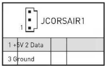
CORSAIR RGB LED Fan Connection![graph TD A["SATA power"] --> B["CORSAIR fan hub"] C["CORSAIR RGB LED fan"] -->|3| B D["CORSAIR RGB LED Extension Cable"] -->|2| B B --> E["JCORSAIR1 connector"] B --> F["4"] B --> G["5"] B --> H["6"]](/content/2026/06/1350721/images/7e634aa285edde1c9ee6d9df1183f994502c64dc002b0179332cd4953534a59f.jpg)
CORSAIR Lighting Node PRO Connection
Important
Fans must start at 1 and continue in series. 1 > 2 > 3 > 4 > 5 > 6. Any fan not connected in series will break communication and the RGB LED lighting function will not work.
Quantity of RGB LED Fans or RGB LED Lighting PRO strips supported may differ between models. Please refer to the motherboard specification.
CORSAIR RGB LED Fan and CORSAIR Lighting Node PRO can't be used at the same time.
Onboard LEDs
EZ Debug LED
These LEDs indicate the debug status of the motherboard.

CPU - indicates CPU is not detected or fail. DRAM - indicates DRAM is not detected or fail. VGA - indicates GPU is not detected or fail. BOOT - indicates the booting device is not detected or fail.
DIMM LEDs
These LED indicate the memory modules are installed.

XMP LED
This LED indicates the XMP (Extreme Memory Profile) mode is enabled.

Multi-BIOS LEDs
Multi-BIOS LEDs indicate which BIOS ROM is in operation.

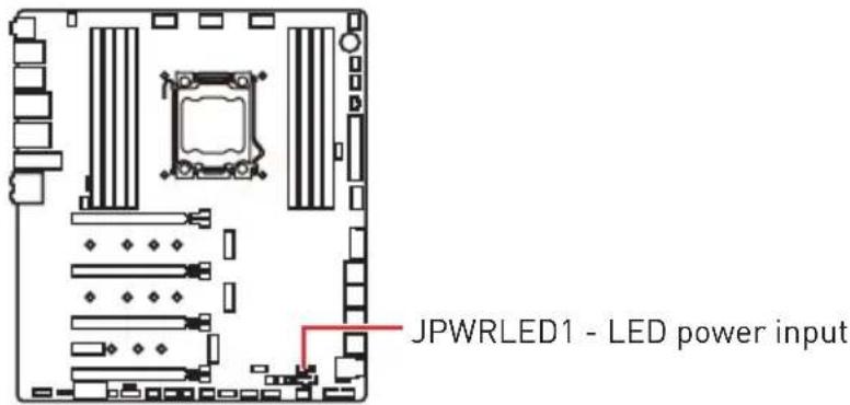
JPWRLED1: LED power input
This connector is used by retailers to demonstrate onboard LED light effects.
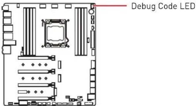
Debug Code LED
The Debug Code LED displays progress and error codes during and after POST. Refer to the Debug Code LED table for details.
Hexadecimal Character Table
| Hexadecimal 0 | 1 2 | 3 4 5 | 6 7 | 8 9 A | B C | D E | F | ||||||||
| Debug CodeLED display | 0 | 12 | 34 | 56 | 789 | Pb | Cd | EF |
Boot Phases
Security (SEC) – initial low-level initialization
Pre-EFI Initialization (PEI) - memory initialization
Driver Execution Environment (DXE) - main hardware initialization
Boot Device Selection (BDS) - system setup, pre-OS user interface & selecting a bootable device (CD/DVD, HDD, USB, Network, Shell, ...)
Debug Code LED Table
SEC Progress Codes
| 01 Power on. Reset type detection (soft/hard) |
| 02 AP initialization before microcode loading |
| 03 System Agent initialization before microcode loading |
| 04 PCH initialization before microcode loading |
| 06 Microcode loading |
| 07 AP initialization after microcode loading |
| 08 System Agent initialization after microcode loading |
| 09 PCH initialization after microcode loading |
| 0B Cache initialization |
SEC Error Codes
| OC - 0D Reserved for future AMI SEC error codes |
| OE Microcode not found |
| OF Microcode not loaded |
PEI Progress Codes
| 10 PEI Core is started | |
| 11 Pre-memory CPU initialization is started | |
| 12 - 14 Pre-memory CPU initialization (CPU module specific) | |
| 15 Pre-memory System Agent initialization is started | |
| 16 - 18 Pre-Memory System Agent initialization (System Agent module specific) | |
| 19 Pre-memory PCH initialization is started | |
| 1A - 1C Pre-memory PCH initialization (PCH module specific) | |
| 2B Memory initialization. Serial Presence Detect (SPD) data reading | |
| 2C Memory initialization. Memory presence detection | |
| 2D Memory initialization. Programming memory timing information | |
| 2E Memory initialization. Configuring memory | |
| 2F Memory initialization (other) | |
| 31 Memory Installed | |
| 32 CPU post-memory initialization is started | |
| 33 CPU post-memory initialization. Cache initialization | |
| 34 | CPU post-memory initialization. Application Processor(s) (AP) initialization |
| 35 CPU post-memory initialization. Boot Strap Processor (BSP) selection | |
| 36 | CPU post-memory initialization. System Management Mode (SMM) initialization |
| 37 Post-Memory System Agent initialization is started | |
| 38 - 3A Post-Memory System Agent initialization (System Agent module specific) | |
| 3B Post-Memory PCH initialization is started | |
| 3C - 3E Post-Memory PCH initialization (PCH module specific) | |
| 4F DXE IPL is started | |
PEI Error Codes
| 50 | Memory initialization error. Invalid memory type or incompatible memory speed |
| 51 Memory initialization error. SPD reading has failed | |
| 52 | Memory initialization error. Invalid memory size or memory modules do not match |
| 53 Memory initialization error. No usable memory detected | |
| 54 Unspecified memory initialization error | |
| 55 Memory not installed | |
| 56 Invalid | CPU type or Speed |
| 57 CPU mismatch | |
| 58 CPU self test failed or possible CPU cache error | |
| 59 CPU micro-code is not found or micro-code update is failed | |
| 5A Internal CPU error | |
| 5B Reset PPI is not available | |
| 5C - 5F Reserved for future AMI error codes | |
DXE Progress Codes
| 60 DXE Core is started |
| 61 NVRAM initialization |
| 62 Installation of the PCH Runtime Services |
| 63 CPU DXE initialization is started |
| 64 - 67 CPU DXE initialization (CPU module specific) |
| 68 PCI host bridge initialization |
| 69 System Agent DXE initialization is started |
| 6A System Agent DXE SMM initialization is started |
| 6B - 6F System Agent DXE initialization (System Agent module specific) |
| 70 PCH DXE initialization is started |
| 71 PCH DXE SMM initialization is started |
| 72 PCH devices initialization |
| 73 - 77 PCH DXE Initialization (PCH module specific) |
| 78 ACPI module initialization |
| 79 CSM initialization |
| 7A - 7F Reserved for future AMI DXE codes |
| 90 Boot Device Selection (BDS) phase is started |
| 91 Driver connecting is started |
| 92 PCI Bus initialization is started |
| 93 PCI Bus Hot Plug Controller Initialization |
| 94 PCI Bus Enumeration 32 |
| 95 PCI Bus Request Resources |
| 96 PCI Bus Assign Resources |
| 97 Console Output devices connect |
| 98 Console input devices connect |
| 99 Super IO Initialization |
| 9A USB initialization is started |
| 9B USB Reset |
| 9C USB Detect |
| 9D USB Enable |
| 9E -9F Reserved for future AMI codes |
| A0 IDE initialization is started |
| A1 IDE Reset |
| A2 IDE Detect |
| A3 IDE Enable |
| A4 SCSI initialization is started |
| A5 SCSI Reset |
| A6 SCSI Detect |
| A7 SCSI Enable |
| A8 Setup Verifying Password |
| A9 Start of Setup |
| AB Setup Input Wait |
| AD Ready To Boot event |
| AE Legacy Boot event |
| AF Exit Boot Services event |
| B0 Runtime Set Virtual Address MAP Begin |
| B1 Runtime Set Virtual Address MAP End |
| B2 Legacy Option ROM Initialization |
| B3 System Reset |
| B4 USB hot plug |
| B5 PCI bus hot plug |
| B6 Clean-up of NVRAM |
| B7 Configuration Reset (reset of NVRAM settings) |
| B8 - BF Reserved for future AMI codes |
DXE Error Codes
| D0 CPU initialization error | |
| D1 System | Agent initialization error |
| D2 PCH initialization error | |
| D3 Some of the Architectural Protocols are not available | |
| D4 PCI resource allocation error. Out of Resources | |
| D5 No Space for Legacy Option ROM | |
| D6 No Console Output Devices are found | |
| D7 No Console Input Devices are found | |
| D8 Invalid password | |
| D9 Error loading Boot Option (LoadImage returned error) | |
| DA Boot Option is failed (StartImage returned error) | |
| DB Flash update is failed | |
DC Reset protocol is not available
S3 Resume Progress Codes
| E0 S3 Resume is stared (S3 Resume PPI is called by the DXE IPL) | |
| E1 S3 Boot Script execution | |
| E2 Video repost | |
| E3 OS S3 wake vector call | |
| E4 - E7 Reserved for future AMI progress codes |
S3 Resume Error Codes
| E8 S3 Resume Failed |
| E9 S3 Resume PPI not Found |
| EA S3 Resume Boot Script Error |
| EB S3 OS Wake Error |
| EC - EF Reserved for future AMI error codes |
Recovery Progress Codes
| F0 Recovery condition triggered by firmware (Auto recovery) |
| F1 Recovery condition triggered by user (Forced recovery) |
| F2 Recovery process started |
| F3 Recovery firmware image is found |
| F4 Recovery firmware image is loaded |
| F5 - F7 Reserved for future AMI progress codes |
Recovery Error Codes
| F8 Recovery PPI is not available |
| F9 Recovery capsule is not found |
| FA Invalid recovery capsule |
| FB - FF Reserved for future AMI error codes |
ACPI States Codes
The following codes appear after booting and the operating system into ACPI modes.
| 01 System | is entering S1 sleep state |
| 02 System | is entering S2 sleep state |
| 03 System | is entering S3 sleep state |
| 04 System | is entering S4 sleep state |
| 05 System | is entering S5 sleep state |
| 10 System | is waking up from the S1 sleep state |
| 20 System | is waking up from the S2 sleep state |
| 30 System | is waking up from the S3 sleep state |
| 40 System | is waking up from the S4 sleep state |
| AC | System has transitioned into ACPI mode. Interrupt controller is in PIC mode. |
| AA | System has transitioned into ACPI mode. Interrupt controller is in APIC mode. |
CPU Temperature
| 00 - 99 | Displays current CPU temperature after the system has fully booted into the OS. |
Installing OS, Drivers & Utilities
Please download and update the latest utilities and drivers at www.msi.com
Installing Windows 10
- Power on the computer.
- Insert the Windows 10 installation disc/USB into your computer.
- Press the Restart button on the computer case.
- Press F11 key during the computer POST (Power-On Self Test) to get into Boot Menu.
- Select the Windows 10 installation disc/USB from the Boot Menu.
- Press any key when screen shows Press any key to boot from CD or DVD... message.
- Follow the instructions on the screen to install Windows 10.
Installing Drivers
- Start up your computer in Windows 10.
- Insert MSI Driver Disc into your optical drive.
- Click the Select to choose what happens with this disc pop-up notification, then select Run DVDSetup.exe to open the installer. If you turn off the AutoPlay feature from the Windows Control Panel, you can still manually execute the DVDSetup.exe from the root path of the MSI Driver Disc.
- The installer will find and list all necessary drivers in the Drivers/Software tab.
- Click the Install button in the lower-right corner of the window.
- The drivers installation will then be in progress, after it has finished it will prompt you to restart.
- Click OK button to finish.
- Restart your computer.
Installing Utilities
Before you install utilities, you must complete drivers installation.
- Open the installer as described above.
- Click the Utilities tab.
- Select the utilities you want to install.
- Click the Install button in the lower-right corner of the window.
- The utilities installation will then be in progress, after it has finished it will prompt you to restart.
- Click OK button to finish.
- Restart your computer.
MYSTIC LIGHT
MYSTIC LIGHT is an application that allows you to control LED light effects of MSI & partner products. For some earlier products, you can go to product download page to download the applicable LED control software.
Device LED effect control screen
When you start up MYSTIC LIGHT, there will be a list of auto-detected devices on the top of the screen. You can click the device icon to switch control screen between devices from the list and you can synchronize their LED effects.
To change LED effect, select the device and LED area you wish, and then select a LED effect from on the left column.

- Light effect selector - allow you to select LED light effects. Please note that for light effect, the option would be more or less depending on the devices you have, it will only list the light effects which are available for all included devices. Each page of effect selector lists six effects, you can use the page navigation on the bottom to find more options.
- LED Color selector - In this section, you may select the color for single light effects (Stack, Breathing, Flashing etc.).

There are four custom color slots on the outer arc and six unchangeable default colors on the inner arc. You can simply change LED color by clicking a color on the outer or inner arc. To change the custom colors, click one of the color slots on the outer arc to store the color of your choice.

Then use the Hue Circle to choose the color you want. The color you choose will be displayed on the center circle. Drag the brightness slider up to increase brightness or drag down to decrease brightness.

You can specify a color by editing an RGB (red, green, blue) value between 0 and 255.
- LED area selector - allows you to select the LED area on the device. The LED effects vary depending on your LED area selection.
- Effect speed level - allows you to adjust the LED light effect switching speed. Please note that this function will only be available if your device supports it.
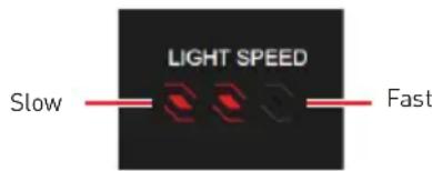
Select more dots to increase the rate of change of the effect and fewer dots to decrease the speed.
- Brightness level - allows you to adjust LED light brightness. Please note that this function will only be available if your device supports it.

Select more dots to increase the LED brightness and fewer dots to decrease the LED brightness.
- Apply Button - Each time you change the configurations, you need to click the Apply button to apply changes.

- Device synchronization - In this section, you may synchronize LED light effect to your devices.
- To synchronize devices - click the chain icon under device icon, when the broken-chain icon changes to the red-chain icon, the device has synchronized the LED effect settings with the other devices.
![graph LR MB["MB"] --> G1["G"] MB --> G2["G"] DRAM["DRAM"] --> G3["G"] DRAM --> G4["G"]](/content/2026/06/1350721/images/5ee6a4504135eed7690b9ac94af1d489931070b2333c99ee68601dc53209b70b.jpg)
Red-chain icon - indicates the device has been synchronized. Broken-chain icon - indicates the device is not synchronized.
- Individual - You can also change settings for single device. To do that, click the chain icon and turn the color to gray as below.

Device icon - click it to enter the device LED effect setting screen. When it is turn red, it indicates the device you're currently setting.
- Synchronize all - There is a quick button on the upper right that allows you to synchronize all your devices with one click. Click the All Sync button, then the chain icons under all sync devices will be changed to red-chain icons and the Profile control panel will appear on the left.

■ Profile control panel - used to save All Sync profile settings.

Save button - saves sync device settings and lighting effect settings to the current Sync Profile.
Nahimic 3
Nahimic 3 is designed to offer the best audio experience. It contains audio effects, microphone effects, and Sound Tracker.
Installation and Update
Nahimic 3 is included in the audio driver. If you need to install it or update it, please use the Driver Disc with your motherboard or download the driver from MSI's official website.
Audio Tab
From this tab, you can access all of Nahimic 3's audio effects, audio profiles, and settings.

- Device display & Volume - displays the type of audio device currently being used as output, as well as its current volume.
- Mute - mutes the current audio output device.
- Audio profiles - allows you to choose between 4 factory audio profiles to fit your multimedia experience (Music, Gaming, Movie, or Communication). All profiles can be modified as you wish.
- On/Off Button - allows you to turn all of Nahimic 3's audio effects on or off in one click.
- Audio Effects – allows you to separately control any of the 5 audio effects.
- Surround Sound - it is an audio effect mainly dedicated to headphones acoustic experience.
- Gaming and Movies - virtualizes the multichannel audio stream from the game engine or the movie soundtrack and downmixes it in order to retrieve a multichannel listening experience over your stereo headphones or speakers.
- Music - expands the stereo for a wider sound stage.
- Volume Stabilizer - it maintains a constant volume for all elements of the audio experience (dialogs, soundtrack, explosions, etc.) to make them all sound softer, balanced or louder. The Quiet On / Off option allows to enter a night mode by removing some basses. This way, you won't disturb people around you if you're using speakers to play your media.
- Voices - it boosts (or removes) the speech in movies, video games and incoming communication from -12 to +12 dB.
- Bass - increases (or decreases) the energy in low frequencies from -12 to +12 dB.
- Treble - increases (or decreases) the energy in high frequencies from -12 to +12 dB.
- Reset Button - restores the current profile to its default values.
- Try Button - launches an audio sample that allows to test audio settings.
Microphone Tab
From this tab, you can access all of Nahimic 3's microphone effects and settings.
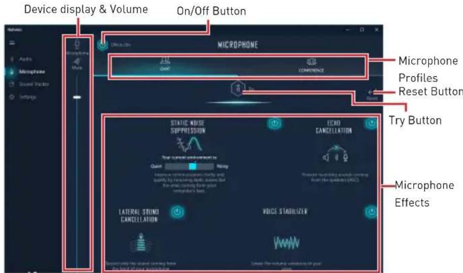
- Device display and volume - displays the type of recording device currently being used as input, as well as its current volume.
■ Mute - mutes the current mic device.
- Mic profiles - allows you to choose between 2 factory mic profiles to fit your experience (Chat or Conference). All profiles can be modified as you wish.
- On / Off button - allows you to turn on and off all Nahimic 3's microphone effects in one click.
- Microphone Effects - allows you to separately control any of the 4 microphone effects.
- Static Noise Suppression - it removes the static noises like the ones coming from your computer fans.
- Echo Cancellation - improves the voice quality by cancelling the echo.
- Lateral Sound Cancellation - it only records the sound coming from the front of your microphone.
- Voice Stabilizer - Levels the volume of your voice in order to avoid any saturation and maintains a constant and clear communication.
- Reset Button - restores the current profile to its default values.
- Try Button - Turns the microphone loopback On/Off.
Sound Tracker Tab
The Sound Tracker is an FPS oriented feature that provides a visual indication localizing the sources of the sounds while in a game. These are represented by dynamic segments pointing the direction of the sounds: the more opaque they are, the stronger the sounds are. Thanks to this feature, players are able to pick up an approaching threat more definitively and easily, thereby being even more dynamic. The Sound Tracker captures the 5.1 and 7.1 sound streams processed by your audio system, and is displayed in the applications and games using DirectX 9, 9c, 10 and 11.

- ON / OFF Button - allows you to enable/ disable the Sound Tracker by switching this option ON/ OFF.
- Try Button - launch a 7.1 audio sample allowing you to preview how the radar will react in your game.
- Sound Tracker Effects
- Size - allows you to adjust the scale of the Sound Tracker, making it look bigger or smaller.
- Transparency - allows you to adjust the transparency of the Sound Tracker, making it look more or less discrete.
- Color - click the colored circle to open the color edition window. You can apply the color you want to the dynamic segments.
- Compatible games - clicking this link opens the official Nahimic website, and leads to the list of compatible games able to display the Sound Tracker.
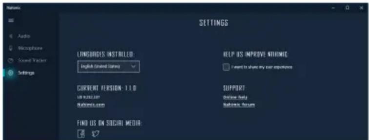
Settings Tab
In this section, you can select the language of the Nahimic 3 user interface.
BIOS Setup
The default settings provide optimal performance for system stability under normal conditions. You should always keep the default settings to avoid possible system damage or boot failure unless you are familiar with BIOS.
Important
BIOS items are continuously updated for better system performance. Therefore, the description may differ slightly from the latest BIOS and should be used for reference only. You can also refer to the HELP information panel for BIOS item descriptions.
The pictures in this chapter are for reference only and may vary from the product you purchased.
Entering BIOS Setup
Please refer to the following methods to enter BIOS setup.
- Press the Delete key when the message "Press DEL key to enter Setup Menu, F11 to enter Boot Menu" appears on the screen during the boot process.
- In the MSI Dragon Center application, click the GO2BIOS button and choose OK. The system will reboot and enter BIOS setup directly.
Function key
F1: General Help
F2: Add/Remove a favorite item
F3: Enter Favorites menu
F4: Enter CPU Specifications menu
F5: Enter Memory-Z menu
F6: Load optimized defaults
F7: Switch between Advanced mode and EZ mode
F8: Load Overclocking Profile
F9: Save Overclocking Profile
F10: Save Change and Reset*
F12: Take a screenshot and save it to USB flash drive (FAT/ FAT32 format only).
Ctrl+F: Enter Search page
* When you press F10, a confirmation window appears and it provides the modification information. Select between Yes or No to confirm your choice.
Resetting BIOS
You might need to restore the default BIOS setting to solve certain problems. There are several ways to reset BIOS:
- Go to BIOS and press F6 to load optimized defaults.
- Short the Clear CMOS jumper on the motherboard.

Important
Be sure the computer is off before clearing CMOS data. Please refer to the Clear CMOS jumper section for resetting BIOS.
Updating BIOS
Updating BIOS with M-FLASH
Before updating:
Please download the latest BIOS file that matches your motherboard model from MSI website. And then save the BIOS file into the USB flash drive.
Updating BIOS:
- Insert the USB flash drive that contains the update file into the USB port.
- Please refer the following methods to enter flash mode.
- Reboot and press Ctrl + F5 key during POST and click on Yes to reboot the system.
- Reboot and press Del key during POST to enter BIOS. Click the M-FLASH button and click on Yes to reboot the system.
- Select a BIOS file to perform the BIOS update process.
- When prompted, switch to the target BIOS ROM with the Multi-BIOS switch, and click Yes to start recovering the BIOS.
- After the flashing process is 100% complete, the system will reboot automatically.
Updating the BIOS with MSI DRAGON CENTER
Before updating:
Make sure the LAN driver is already installed and the Internet connection is set up properly.
Updating BIOS:
- Install and launch MSI DRAGON CENTER.
- Select BIOS Update.
- Click on the Scan button.
- Click on the Download icon to download and install the latest BIOS file.
- Click Next and choose In Windows mode. Then click Next and Start to begin updating the BIOS.
- After the flashing process is 100% complete, the system will restart automatically.
Updating BIOS with BIOS FLASHBACK+
Before updating:
Please download the latest BIOS file that matches your motherboard model from the MSI® website and rename the BIOS file to MSI.ROM. Then, save the MSI.ROM file to the root of a USB flash drive.

Important
Only the FAT32 format USB flash drive supports updating BIOS by BIOS FLASHBACK+.
- Connect power supply to CPU_PWR1 and ATX_PWR1. (No other components are necessary but power supply.)
- Plug the USB flash drive that contains the MSI.ROM file into the BIOS FLASHBACK+ port on rear I/O panel.
- Press the BIOS FLASHBACK+ button to flash BIOS, and the LED on the FLASHBACK+ button starts flashing.
- After the flashing BIOS process is 100% completed, the LED would be off simultaneously.
EZ Mode
At EZ mode, it provides the basic system information and allows you to configure the basic setting. To configure the advanced BIOS settings, please enter the Advanced Mode by pressing the Setup Mode switch or F7 function key.

- GAME BOOST switch - click on the center button to switch GAME BOOST control between software (SW) and hardware (HW). The inner circle represents the current stage of hardware GAME BOOST and the outer circle stands for software. You can read the CPU frequency of each GAME BOOST stage by clicking on the ? icon at right-bottom corner.
Important
Please don't make any changes in OC menu and don't load defaults to keep the optimal performance and system stability after activating the GAME BOOST function.
- XMP switch - click on the inner circle to enable/ disable the X.M.P. (Extreme Memory Profile). Switch the outer circle to select the X.M.P. profile. This switch will only be available if the X.M.P. supported memory module is installed.
- Setup Mode switch - press this tab or the F7 key to switch between Advanced mode and EZ mode.
- Screenshot - click on this tab or the F12 key to take a screenshot and save it to USB flash drive (FAT/ FAT32 format only).
- Search - click on this tab or the Ctrl+F keys and the search page will show. It allows you to search by BIOS item name, enter the item name to find the item listing. Move the mouse over a blank space and right click the mouse to exit search page.
Important
In search page, only the F6, F10 and F12 function keys are available.
- Language - allows you to select the language of BIOS setup.
- System information - shows the CPU/ DDR speed, CPU/ MB temperature, MB/ CPU type, memory size, CPU/ DDR voltage, BIOS version and build date.
- Boot device priority bar - you can move the device icons to change the boot priority. The boot priority from high to low is left to right.
- Information display - click on the CPU, Memory, Storage, Fan Info and Help buttons on left side to display related information.
- Function buttons - enable or disable the LAN Option ROM, M.2/Optane Genie, HD audio controller, AHCI, RAID, CPU Fan Fail Warning Control and BIOS Log Review by clicking on their respective button.
- M-Flash - click on this button to display the M-Flash menu that provides the way to update BIOS with a USB flash drive.
- Hardware Monitor - click on this button to display the Hardware Monitor menu that allows you to manually control the fan speed by percentage.
- Favorites - press the Favorites tab or the F3 key to enter Favorites menu. It allows you to create personal BIOS menu where you can save and access favorite/ frequently-used BIOS setting items.
- Default HomePage - allows you to select a BIOS menu (e.g. SETTINGS, OC...,etc) as the BIOS home page.
- Favorite1\~5 - allows you to add the frequently-used/ favorite BIOS setting items in one page.
- To add a BIOS item to a favorite page (Favorite 1\~5)
- Move the mouse over a BIOS item not only on BIOS menu but also on search page.
- Right-click or press the F2 key.
- Choose a favorite page and click OK.
- To delete a BIOS item from the favorite page
- Move the mouse over a BIOS item on the favorite page (Favorite 1\~5)
- Right-click or press the F2 key.
- Choose Delete and click OK.
Advanced Mode
Press the Setup Mode switch or the F7 function key to switch between EZ Mode and Advanced Mode in the BIOS setup.

- GAME BOOST switch/ XMP switch/ Setup Mode switch/ Screenshot/ Language/ System information/ Boot device priority bar - please refer to the descriptions in the EZ Mode Overview section.
- BIOS menu selection - the following options are available:
- SETTINGS - allows you to specify the parameters for the chipset and boot devices.
- OC - allows you to adjust the frequency and voltage. Increasing the frequency may get better performance.
- M-FLASH - provides a way to update the BIOS with a USB flash drive.
- OC PROFILE - allows you to manage overclocking profiles.
- HARDWARE MONITOR - allows you to set the speeds of fans and monitor voltages of system.
- BOARD EXPLORER - provides the information of installed devices on this motherboard.
- Menu display - provides BIOS setting items and information to be configured.
SETTINGS

System Status
▶ System Date
Sets the system date. Use tab key to switch between date elements.
The format is .
Day of the week, from Sun to Sat, determined by BIOS. Read-only.
The month from Jan. through Dec.
The date from 1 to 31 can be keyed by numeric function keys.
The year can be adjusted by users.
▶ System Time
Sets the system time. Use tab key to switch between time elements.
The time format is .
▶ SATA PortX/ M2_X
Shows the information of connected SATA/ M.2 devices.

Important
If the connected SATA device is not displayed, turn off computer and re-check SATA cable and power cable connections of the device and motherboard.
▶ System Information
Shows detailed system information, including CPU type, BIOS version, and Memory (read only).
▶ DMI Information
Shows system information, desktop Board Information and chassis Information. (Read only).
Advanced
PCI Subsystem Settings
Sets PCI, PCI express interface protocol and latency timer. Press Enter to enter the sub-menu.
▶PEG X - Max Link Speed [Auto]
Sets PCI Express protocol of PCIe x16 slots for matching different installed devices.
[Auto] This item will be configured automatically by BIOS.
[Gen1] Enables PCIe Gen1 support only.
[Gen2] Enables PCIe Gen2 support only.
[Gen3] Enables PCIe Gen3 support only.
▶Above 4G memory/ Crypto Currency mining [Disabled]
Enables or disables 64-bit capable devices to be decoded in above 4G address space. It is only available if the system supports 64-bit PCI decoding.
[Enabled] Allows you to utilize more than 4x GPUs.
[Disabled] Disables this function.
▶MMIO High Granularity Size [1G]
Selects the allocation size used to assign memory-mapped I/O (MMIO) resources.
[Options:1G, 4G, 16G, 64G, 256G, 1024G]
▶ VROC Configuration
This submenu allows you to enable or disable the PCIe slots to support the RAID function built by SSDs.
▶ ACPI Settings
Sets ACPI parameters of onboard power LED behaviors. Press Enter to enter the sub-menu.
▶ Power LED [Blinking]
Sets shining behaviors of the onboard Power LED.
[Dual Color] The power LED turns to another color to indicate the S3 state.
[Blinking] The power LED blinks to indicate the S3 state.
▶ CPU Over Temperature Alert [Auto]
Enables or disables the CPU overheating alert when CPU temperature is over 80 degrees centigrade.
▶ Integrated Peripherals
Sets integrated peripherals' parameters, such as LAN, HDD, USB and audio. Press Enter to enter the sub-menu.
▶ Onboard LAN Controller [Enabled]
Enables or disables the onboard LAN controller.
▶ Onboard LAN Controller2 [Enabled]
Enables or disables the onboard LAN controller2.
▶ LAN Option ROM [Disabled]
Enables or disables the legacy network Boot Option ROM for detailed settings. This item will appear when Onboard LAN Controller is enabled.
[Enabled] Enables the onboard LAN Boot ROM.
[Disabled] Disables the onboard LAN Boot ROM.
▶ Network Stack [Disabled]
Sets UEFI network stack for optimizing IPv4 / IPv6 function.
[Enabled] Enables UEFI network stack.
[Disabled] Disables UEFI network stack.
▶Ipv4 PXE Support [Enabled]
When Enabled, the system UEFI network stack will support IPv4 protocol. This item will appear when Network Stack is enabled.
[Enabled] Enables the IPv4 PXE boot support.
[Disabled] Disables the IPv4 PXE boot support.
▶Ipv6 PXE Support [Enabled]
When Enabled, the system UEFI network stack will support IPv6 protocol. This item will appear when Network Stack is enabled.
[Enabled] Enables the IPv6 PXE boot support.
[Disabled] Disables the IPv6 PXE boot support.
▶ SATA Mode [AHCI Mode]
Sets the operation mode of the onboard SATA controller.
[AHCI Mode] Specify the AHCI mode for SATA storage devices. AHCI (Advanced Host Controller Interface) offers some advanced features to enhance the speed and performance of SATA storage device, such as Native Command Queuing (NCQ) and hot-plugging.
[Optane Mode] Enables Optane function for NVMe or PCIe storage devices.
▶ M2_X-RST PCIe Storage Remapping [Disabled]
Enables or disables M.2 PCIe storage remapping for Intel Rapid Storage.
▶ M.2/Optane Genie [Disabled]
Enables or disables M.2 storage/Optane memory.
▶ SATAx Hot Plug [Disabled]
Allows the user to enable or disable SATA hot plug support.
[Enabled] Enables hot plug support for the SATA ports.
[Disabled] Disables hot plug support for the SATA ports.
▶ HD Audio Controller [Enabled]
Enables or disables the onboard High Definition Audio controller.
▶ Thunderbolt(TM) Configuration
▶ Discrete Thunderbolt(TM) Support [Disabled]
Enables or disables Thunderbolt™ support.
USB Configuration
Sets the onboard USB controller and device function. Press Enter to enter the sub-menu.
▶USB Controller [Enabled]
Enables or disables all USB controllers.
▶XHCI Hand-off [Disabled]
Enables or disables XHCI hand-off support for the operating system without XHCI hand-off feature.
▶ Legacy USB Support [Enabled]
Sets Legacy USB function support.
[Auto] The system will automatically detect if any USB device is connected and enable the legacy USB support.
[Enabled] Enable the USB support under legacy mode.
[Disabled] The USB devices will be unavailable under legacy mode.
▶ Power Management Setup
Sets system Power Management of ErP and AC Power Loss behaviors. Press Enter to enter the sub-menu.
▶ErP Ready [Disabled]
Enables or disables the system power consumption according to ErP regulation.
[Enabled] Optimize the system power consumption according to ErP regulation. It will not support S4 & S5 wake up by USB, PCI and PCIe devices.
[Disabled] Disables this function.
▶ Restore after AC Power Loss [Power Off]
Sets the system behaviors while encountering the AC power loss.
[Power Off] Leaves the system in power off state after restoring AC power.
[Power On] Boot up the system after restoring AC power.
[Last State] Restores the system to the previous state (power on/ power off) before AC power loss.
▶ System Power Fault Protection [Disabled]
Enables or disables the system to boot up when detecting abnormal voltage input.
[Enabled] Protect the system from unexpected power operation and remain the shut down status.
[Disabled] Disables this function.
▶ Windows OS Configuration
Sets Windows OS detailed configuration and behaviors. Press Enter to enter the sub-menu.
▶ Windows 10 WHQL Support [Disabled]
Enables the supports for Windows 10 or disables for other operating systems.
Before enabling this item, make sure all installed devices & utilities (hardware & software) should meet the Windows 10 requirements.
[Enabled] The system will switch to UEFI mode to meet the Windows requirement.
[Disabled] Disables this function.
▶ MSI Fast Boot [Disabled]
MSI Fast Boot is the fastest way to boot the system. It will disable more devices to speed up system boot time which is faster than the boot time of Fast Boot.
[Enabled] Enables the MSI Fast Boot function to speed up booting time. And the following Fast Boot field will be disabled and fixed.
[Disabled] Disables MSI Fast Boot.
Important
When MSI Fast Boot is enabled, you can use MSI FAST BOOT application to enter BIOS setup if needed. Please refer Entering BIOS Setup section for details.
▶ Fast Boot [Enabled]
Enables or disables the fast boot feature for Windows 10. This item will only be available when MSI Fast Boot is disabled.
[Enabled] Enables the Fast Boot configuration to accelerate system boot time.
[Disabled] Disables the Fast Boot configuration.
▶ Internal GOP Configuration
Manages the onboard Graphics Output Protocol (GOP). Press Enter to enter the sub-menu. This sub-menu will appear when Windows 10 WHQL Support is enabled.
▶ Secure Boot
Sets the Windows secure boot to prevent the unauthorized accessing. Press Enter to enter the sub-menu. This sub-menu will appear when Windows 10 WHQL Support is enabled.
▶ Secure Boot Support [Disabled]
Enables or disables secure boot support.
[Enabled] Enables the secure boot function and allows you to set the secure boot settings.
[Disabled] Disables this function.
▶ Secure Boot Mode [Standard]
Selects the secure boot mode. This item is used to select how the secure boot keys are loaded. This item appears when Secure Boot Support is enabled.
[Standard] The system will automatically load the secure keys from BIOS.
[Custom] Allows the user to configure the secure boot settings and manually load the secure keys.
▶ Key Management
Manages the secure boot keys. Press to enter the sub-menu. This sub-menu will appear when Secure Boot Mode is set to Custom.
▶ Wake Up Event Setup
Sets system wake up behaviors for different sleep modes. Press Enter to enter the sub-menu.
▶ Wake Up Event By [BIOS]
Selects the wake up event by BIOS or operating system.
[BIOS] Activates the following items, and sets wake up events for these items.
[OS] The wake up events will be defined by OS.
▶ Resume By RTC Alarm [Disabled]
Disables or enables the system wake up by RTC Alarm.
[Enabled] Enables the system to boot up on a scheduled time/date.
[Disabled] Disables this function.
▶ Date (of month) Alarm/ Time (hh:mm:ss) Alarm
Sets RTC alarm date/ Time. If Resume By RTC Alarm is set to [Enabled], the system will automatically resume (boot up) on a specified date/hour/minute/second in these fields (using the + and - keys to select the date & time settings).
▶ Resume By PCI-E Device [Disabled]
Enables or disables the wake up function of installed PCI-E expansion cards, integrated LAN controllers or USB devices which are supported by third party integrated chips.
[Enabled] Enables the system to be awakened from the power saving modes when activity or input signal of PCIe device is detected.
[Disabled] Disables this function.
▶ Resume By Onboard Intel LAN [Disabled]
Enables or disables the system wake up by Onboard Intel LAN.
[Enabled] Enables the system to be awakened from the power saving modes when activity or input signal of Intel LAN device is detected.
[Disabled] Disables this function.
Resume by USB Device [Disabled]
Enables or disables the system wake up by USB devices.
[Enabled] Enables the system to be awakened from sleep state when activity of USB device is detected.
[Disabled] Disables this function.
Resume From S3/S4/S5 by PS/2 Mouse [Disabled]
Enables or disables the system wake up by PS/2 mouse.
[Enabled] Enables the system to be awakened from S3/ S4/ S5 state when activity of PS/2 mouse is detected.
[Disabled] Disables this function.
Resume From S3/S4/S5 by PS/2 Keyboard [Disabled]
Enables or disables the system wake up by PS/2 keyboard.
[Any Key] Enables the system to be awakened from S3/S4/S5 state when activity of any key on PS/2 keyboard is detected.
[Hot Key] Enables the system to be awakened from S3/ S4/ S5 state when activity of hot key on PS/2 keyboard is detected.
[Disabled] Disables this function.
Hot Key [Ctrl+Space]
Selects a combination of keys as a hot key to wake the system. This item appears when you set the Resume From S3/S4/S5 by PS/2 Keyboard to Hot Key.
▶ Secure Erase+
Enables or disables Secure Erase+ function. Secure Erase+ is the best way to effectively wipe all data from a SSD. Please note that data of SSD will be erased after enabling Secure Erase+.
Boot
Sets the sequence of system boot devices.
▶ Full Screen Logo Display [Enabled]
Enables or disables to show the full screen logo while system POST.
[Enabled] Shows the logo in full screen.
[Disabled] Shows the POST messages.
▶ GO2BIOS [Disabled]
Allows system to enter BIOS setup directly by pressing the Power button for 4 sec pon bootup.
[Enabled] The system boots straight to the BIOS setup by long pressing the power button about 4 seconds when the system is off.
[Disabled] Disables this function.
▶ Bootup NumLock State [On]
Select the keyboard NumLock state upon bootup.
▶ Info Block effect [Unlock]
Sets the state of Help information block.
[Unlock] Sliding effect.
[Lock] Fix the Help information block on the screen.
▶ AUTO CLR_CMOS [Disabled]
Enables or disables the CMOS data to be resumed automatically when the booting process hang-up over 5 seconds.
▶ Boot Mode Select [LEGACY+UEFI]
Sets the system boot mode from legacy or UEFI architecture depending on OS installation requirement. This item will become un-selectable and will be configured automatically by BIOS when Windows 10 WHQL Support is enabled.
[UEFI] Enables UEFI BIOS boot mode support only.
[LEGACY+UEFI] Enables both Legacy BIOS boot mode and UEFI BIOS boot mode.
▶ FIXED BOOT ORDER Priorities
Sets device priority for system boot.
▶ Boot Option Priorities
These items are used to prioritize the installed boot devices.
Security
▶ Administrator Password
Sets administrator password for system security. User has full rights to change the BIOS items with administrator password. After setting the administrator password, the state of this item will show “Installed”.
▶ User Password
Sets User Password for system security. User has limited rights to change the BIOS items with user password. This item will be available when administrator password is set. After setting the user password, the state of this item will show “Installed”.
▶ Password Check [Setup]
Selects a condition that will request the password.
[Setup] A password will be requested for entering the BIOS Setup.
[Boot] A password will be requested for booting the system.
▶ Password Clear [Enabled]
Enables or disables the clear CMOS behavior to clear a set password.
[Enabled] The password will be erased after clear CMOS.
[Disabled] The password will always be kept.
![MSI MEG X299 Creation - ▶ Password Clear [Enabled] - 1](/content/2026/06/1350721/images/e78497d326182cb3833c178f44c41f675f312706290ec560340df2ad528f62cb.jpg)
Important
When selecting the Administrator / User Password items, a password box will appear on the screen. Type the password then press . The password typed now will replace any previous set password from CMOS memory. You will be prompted to confirm the password. You may also press to abort the selection.
To clear a set password, press when you are prompted to enter a new password. A message will confirm the password is being disabled. Once the password is disabled, you can enter the setup and OS without authorization.
▶ Trusted Computing
Sets TPM (Trusted Platform Module) function.
▶ Security Device Support [Disabled]
Enables or disables the TPM function to build the endorsement key for accessing the system.
▶ Chassis Intrusion Configuration
Press to enter the sub-menu.
▶ Chassis Intrusion [Disabled]
Enables or disables recording messages when the chassis is opened. This function is ready for the chassis equips a chassis intrusion switch.
[Enabled] Once the chassis is opened, the system will record and issue a warning message.
[Reset] Clear the warning message. After clearing the message, please return to Enabled or Disabled.
[Disabled] Disables this function.
Save & Exit
▶ Discard Changes and Exit
Exit BIOS setup without saving any change.
▶ Save Changes and Reboot
Save all changes and reboot the system.
Save Changes
Save current changes.
Discard Changes
Discard all changes and restore to the previous values.
Restore Defaults
Restore or load all default values.
Boot Override
The installed bootable devices will appear on this menu, you can select one of them to be the boot device.
OC
![Overclocking OC Explore Mode [Normal] CPU Setting CPU Ratio Auto Adjusted CPU Frequency 3200MHz CPU Ratio Offset When Running AVX [Auto] Ring Ratio Auto Adjusted Ring Frequency 3500MHz GT Ratio Auto Adjusted GT Frequency 1100MHz ■ Misc Setting DRAM Setting DRAM Frequency [Auto] Adjusted DRAM Frequen…](/content/2026/06/1350721/images/840e3c376bea0578e350b5661f741717728aa774d1113470edb13337efbf85e0.jpg)

Important
Overclocking your PC manually is only recommended for advanced users.
Overclocking is not guaranteed, and if done improperly, it could void your warranty or severely damage your hardware.
If you are unfamiliar with overclocking, we advise you to use GAME BOOST function for easy overclocking.
OC Explore Mode [Expert]
Enables or disables to show the normal or expert version of OC settings.
[Normal] Provides the regular OC settings in BIOS setup.
[Expert] Provides the advanced OC settings for OC expert to configure in BIOS setup.
Note: We use * as the symbol for the OC settings of Expert mode.
▶ CPU Ratio Apply Mode [All Core]*
Sets applied mode for CPU ratio. This item only appears when a CPU that supports Turbo Boost is installed.
[All Core] Enables the CPU Ratio. All CPU cores will run the same CPU ratio that be set in CPU Ratio.
[Per Core] Enables the Core X X of X xxxx MHz. Sets each CPU core ratio separately.
[Turbo Ratio] Enables the X-Core Ration Limit. This option only appears when a CPU that supports this function is installed.
▶ X-Core Ratio Limit [Auto]*
Allows you to set the CPU ratios for different number of active cores. These items only appear when CPU Ratio Apply Mode set to Turbo Ratio.
▶ Adjusted CPU Frequency
Shows the adjusted CPU frequency. Read-only.
▶ Core X X of X xxxx MHz [Auto]*
Allows you to set the CPU ratios for different number of active cores. These items only appear when CPU Ratio Apply Mode set to Per Core.
▶ CPU Ratio Offset When Running AVX [Auto]
Sets an offset value to lower the CPU core ratio. It could be helpful for heat dissipation when running AVX instruction set. If set to Auto, BIOS will configure this setting automatically. This item appears when the installed CPU supports this function.
▶ Game Boost Function Control [By Onboard Button]
Enables the GAME BOOST function by virtual button in BIOS or physical button on motherboard. Enabling GAME BOOST function can automatically overclock the system with MSI optimized overclocking profile.
▶ Ring Ratio [Auto]
Sets the ring ratio. The valid value range depends on the installed CPU.
▶ Adjusted Ring Frequency
Shows the adjusted Ring frequency. Read-only.
▶ Misc Setting*
Press Enter, + or - key to open or close the following 3 items related to CPU features.
▶ EIST [Enabled]*
Enables or disables the Enhanced Intel ® SpeedStep Technology.
[Enabled] Enables the EIST to adjust CPU voltage and core frequency dynamically. It can decrease average power consumption and average heat production.
[Disabled] Disables EIST.
▶Intel Turbo Boost [Enabled]*
Enables or disables the Intel ® Turbo Boost. This item appears when the installed CPU supports this function.
[Enabled] Enables this function to boost CPU performance automatically above rated specifications when the system requests the highest performance state.
[Disabled] Disables this function.
▶ Enhanced Turbo [Auto]*
Enables or disables the Enhanced Turbo function for all CPU cores to boost CPU performance. This item appears when the installed CPU supports this function.
[Auto] This setting will be configured automatically by BIOS.
[Enabled] All CPU cores would be increased to the maximum turbo ratio.
[Disabled] Disables this function.
▶ CPU Base Clock (MHz)
Sets the CPU base clock. You may overclock the CPU by adjusting this value. Please note that overclocking behavior and stability are not guaranteed. This item appears when a CPU that supports this function is installed.
▶ CPU Base Clock Apply Mode [Auto]*
Sets the applying mode for the adjusted CPU base clock.
[Auto] This setting will be configured automatically by BIOS.
[Next Boot] CPU will run the adjusted CPU base clock at next boot.
[Immediate] CPU runs the adjusted CPU base clock immediately.
▶ Clockgen Features (optional)
Press Enter to enter the sub-menu. Sets the detailed clockgen features.
▶ Dynamic Frequency Control [Disabled]
Enables or disables to try different CPU BCLK under CPU loading to overclock the system. This item will be disabled when the Dynamic Frequency Search is enabled.
▶ DFC Baseline (MHz) [Auto]
Sets initial BCLK for dynamic overclocking if not reach the threshold. This item will be available when the Dynamic Frequency Control is enabled
▶ Threshold 1\~3 (A) [Auto]
Sets the CPU current as the threshold for Dynamic Frequency Control. When CPU current reaches the value, it will run the Level 1/2/3 BCLK for dynamic overclocking. These items will appear when the Dynamic Frequency Control is enabled.
▶ Level 1\~3 BCLK (MHz) [Auto]
Sets the CPU BCLK for the threshold. These items will appear when the Dynamic Frequency Control is enabled.
▶ Dynamic Frequency Search [Disabled]
Enables or disables to run the optimized dynamic BCLK. This item will be disabled when the Dynamic Frequency Control is enabled.
▶ Dynamic Frequency Search Mode [Once]
Sets the search mode of the dynamic BCLK. This item will be available when the Dynamic Frequency Search is enabled.
[Once] Run once in the next system boot.
[Each Power On] Run in every time when system is powered on.
▶ Dynamic Frequency Search Step (MHz) [Auto]
Sets the increase for running the dynamic BCLK. If set to Auto, BIOS will configure this setting automatically. This item will be available when the Dynamic Frequency Search is enabled.
▶ BCLK Amplitude [Auto]
Sets the value for BCLK Amplitude for overclocking. Higher value might benefit to get higher overclocking.
▶ SRC Clock Amplitude [Auto]
Sets the value for SRC clock Amplitude.
▶ SATA Clock Amplitude [Auto]
Sets the value for SATA clock Amplitude.
▶ BCLK Slew Rate [Auto]
Sets the value for BCLK Slew Rate for overclocking. The value might vary depending on the actual overclocking scenario.
▶ BCLK ORT Duration [Auto]
Sets the value for BCLK ORT duration for overclocking. The value might vary depending on the actual overclocking scenario.
▶ Extreme Memory Profile (X.M.P.) [Disabled]
X.M.P. (Extreme Memory Profile) is the overclocking technology by memory module. Please enable XMP or select a profile of memory module for overclocking the memory. This item will be available when the memory modules that support X.M.P. is installed.
▶ DRAM Reference Clock [Auto]*
Sets the DRAM reference clock. The valid value range depends on the installed CPU. This item appears when a CPU that supports this adjustment is installed.
▶ DRAM Frequency [Auto]
Sets the DRAM frequency. Please note the overclocking behavior is not guaranteed.
▶ Adjusted DRAM Frequency
Shows the adjusted DRAM frequency. Read-only.
▶ Load Memory Presets [Disabled]*
Load OC Memory Preset will optimize the timing, voltage of installed memory module.
![MSI MEG X299 Creation - ▶ Load Memory Presets [Disabled]* - 1](/content/2026/06/1350721/images/fccbb16890a32bd93fbdf4aa9ced94cbf855aa78f466c9296e4fa0012252de87.jpg)
Important
Manual tweaking or fine-tune preferred parameter is still recommended due to different memory module manufacturing quality.
▶ Memory Try It ! [Disabled]
It improve memory compatibility or performance by choosing optimized memory preset.
▶ DRAM Timing Mode [Link]
Selects the memory timing mode.
[Link] Allows user to configure the DRAM timing for all memory channel.
[UnLink] Allows user to configure the DRAM timing for respective memory channel.
▶ Advanced DRAM Configuration
Press Enter to enter the sub-menu. User can set the memory timing for each/ all memory channel. The system may become unstable or unbootable after changing memory timing. If it occurs, please clear the CMOS data and restore the default settings. (Refer to the Clear CMOS jumper/ button section to clear the CMOS data, and enter the BIOS to load the default settings.)
▶ Memory Fast Boot [Auto]*
Enables or disables the initiation and training for memory every booting.
[Auto] The setting will be configured automatically by BIOS.
[Enabled] System will completely keep the archives of first initiation and training for memory. So the memory will not be initialed and trained when booting to accelerate the system booting time.
[Disabled] The memory will be initialed and trained every booting.
▶ CPU Voltages control [Auto]
These options allows you to set the voltages related to CPU. If set to Auto, BIOS will set these voltages automatically or you can set it manually.
▶ DRAM Voltages control [Auto]
These options allows you to set the voltages related to memory. If set to Auto, BIOS will set these voltages automatically or you can set it manually.
▶ CPU Memory Changed Detect [Enabled]*
Enables or disables the system to issue a warning message during boot when the CPU or memory has been replaced.
[Enabled] The system will issue a warning message during boot and then you have to load the default settings for new devices.
[Disabled] Disables this function and keeps the current BIOS settings.
▶ OC Quick View Timer [3 Sec]*
Sets the duration of OC setting values shown on the screen. If set to Disabled, BIOS will not show the variations of OC setting.
▶ CPU Specifications
Press Enter to enter the sub-menu. This sub-menu displays the information of installed CPU. You can also access this information menu at any time by pressing [F4]. Read only.
▶ CPU Technology Support
Press Enter to enter the sub-menu. The sub-menu shows the key features of installed CPU. Read only.
▶ MEMORY-Z
Press Enter to enter the sub-menu. This sub-menu displays all the settings and timings of installed memory. You can also access this information menu at any time by pressing [F5].
▶ DIMMA1/A2/B1/B2/C1/C2/D1/D2 Memory SPD
Press Enter to enter the sub-menu. The sub-menu displays the information of installed memory. Read only.
▶ CPU Features
Press Enter to enter the sub-menu.
▶ Hyper-Threading [Enabled]
Intel Hyper-Threading technology treats the multi cores inside the processor as multi logical processors that can execute instructions simultaneously. In this way, the system performance is highly improved. This item appears when the installed CPU supports this technology.
[Enable] Enables Intel Hyper-Threading technology.
[Disabled] Disables this item if the system does not support HT function.
▶ Active Processor Cores Control [All]
Allows you to select the number of active CPU cores.
▶ Limit CPUID Maximum [Disabled]
Enables or disables the extended CPUID value.
[Enabled] BIOS limits the maximum CPUID input value to circumvent boot problems with older operating systems that do not support the processor with extended CPUID value.
[Disabled] Use the actual maximum CPUID input value.
▶ Intel Virtualization Tech [Enabled]
Enables or disables Intel Virtualization technology.
[Enabled] Enables Intel Virtualization technology and allows a platform to run multiple operating systems in independent partitions. The system can function as multiple systems virtually.
[Disabled] Disables this function.
▶ Intel VT-D Tech [Disabled]
Enables or disables Intel VT-D (Intel Virtualization for Directed I/O) technology.
▶ Hardware Prefetcher [Enabled]
Enables or disables the hardware prefetcher (MLC Streamer prefetcher).
[Enabled] Allows the hardware prefetcher to automatically pre-fetch data and instructions into L2 cache from memory for tuning the CPU performance.
[Disabled] Disables the hardware prefetcher.
Adjacent Cache Line Prefetch [Enabled]
Enables or disables the CPU hardware prefetcher (MLC Spatial prefetcher).
[Enabled] Enables adjacent cache line prefetching for reducing the cache latency time and tuning the performance to the specific application.
[Disabled] Enables the requested cache line only.
CPU AES Instructions [Enabled]
Enables or disables the CPU AES (Advanced Encryption Standard-New Instructions) support. This item appears when a CPU supports this function.
Intel Adaptive Thermal Monitor [Enabled]
Enables or disables the Intel adaptive thermal monitor function to protect the CPU from overheating.
[Enabled] Throttles down the CPU core clock speed when the CPU is over the adaptive temperature.
[Disabled] Disables this function.
Intel C-State [Auto]
Enables or disables the Intel C-state. C-state is a processor power management technology defined by ACPI.
[Auto] This setting will be configured automatically by BIOS.
[Enabled] Detects the idle state of the system and reduces CPU power consumption accordingly.
[Disabled] Disables this function.
▶ C1E Support [Disabled]
Enables or disables the C1E function for power-saving in halt state. This item appears when Intel C-State is enabled.
[Enabled] Enables C1E function to reduce the CPU frequency and voltage for power-saving in halt state.
[Disabled] Disables this function.
▶ Package C State limit [Auto]
This item allows you to select a CPU C-state level for power-saving when the system is idle. The options of C-state depend on the installed CPU. This item appears when Intel C-State is enabled.
▶ CFG Lock [Enabled]
Locks or unlocks the MSR 0xE2[15], CFG lock bit.
[Enabled] Locks the CFG lock bit.
[Disabled] Unlocks the CFG lock bit.
▶ Long Duration Power Limit (W) [Auto]
Sets the long duration TDP power limit for CPU in Turbo Boost mode.
▶ Long Duration Maintained (s) [Auto]
Sets the maintaining time for Long duration Power Limit (W).
▶ Short Duration Power Limit (W) [Auto]
Sets the short duration TDP power limit for CPU in Turbo Boost mode.
▶ CPU Current Limit (A) [Auto]
Sets maximum current limit of CPU package in Turbo Boost mode. When the current is over the specified value, the CPU will automatically reduce the core frequency for reducing the current.
▶ Internal VR OVP OCP Protection [Auto]
Enables or disables the over-voltage protection and over-current protection for CPU internal VR (Voltage Regulator). This item only appears when a CPU that supports this function is installed.
[Auto] This setting will be configured automatically by BIOS.
[Enabled] Enables the limitation of internal VR for over-voltage protection and over-current protection.
[Disabled] Disables this function for overclocking.
▶ Internal VR Efficiency Management [Auto]
Enables or disables the CPU internal VR efficiency management. This item only appears when a CPU that supports this function is installed.
[Auto] This setting will be configured automatically by BIOS.
[Enabled] Enables the VR efficiency management for power-saving control.
[Disabled] Disables this function.
M-FLASH
M-FLASH provides the way to update BIOS with a USB flash drive. Please download the latest BIOS file that matches your motherboard model from MSI website, save the BIOS file into your USB flash drive. And then follow the steps below to update BIOS.
- Insert the USB flash drive that contains the update file into the computer.
- Click on M-FLASH tab, a demand message will be prompted. Click on Yes to reboot and enter the flash mode.

- The system will enter the flash mode and a file selection menu will appear after rebooting.
| File Path : fs0: | |||
| Drive | File | ||
| FSO: General USB Flash Disk 1.0 | 2015/07/01 12:34:56 | < DIR > | BIOSFILE01 |
| 2015/07/02 12:34:56 | < DIR > | BIOSFILE02 | |
| 2015/07/03 12:34:56 | < DIR > | BIOSFILE03 | |
| 2015/07/04 12:34:56 | < DIR > | BIOSFILE04 | |
| 2015/07/05 12:34:56 | < DIR > | BIOSFILE05 | |
| 2015/07/06 12:34:56 | < DIR > | BIOSFILE06 | |
| 2015/07/07 12:34:56 | < DIR > | BIOSFILE07 | |
| 2015/07/08 12:34:56 | < DIR > | BIOSFILE08 | |
| 2015/07/09 12:34:56 | < DIR > | BIOSFILE09 | |
| 2015/07/10 12:34:56 | < DIR > | BIOSFILE10 | |
| [ Current BIOS ] Model Name: Version Build Date: [ Selected BIOS ] Model Name: N/A Version: N/A Build Date: N/A | |||
- Select a BIOS file to perform the BIOS update process.
- When prompted, switch to the target BIOS ROM with Multi-BIOS switch, and click on Yes to start recovering BIOS.
- After the flashing process is 100% completed, the system will reboot automatically.
OC PROFILE
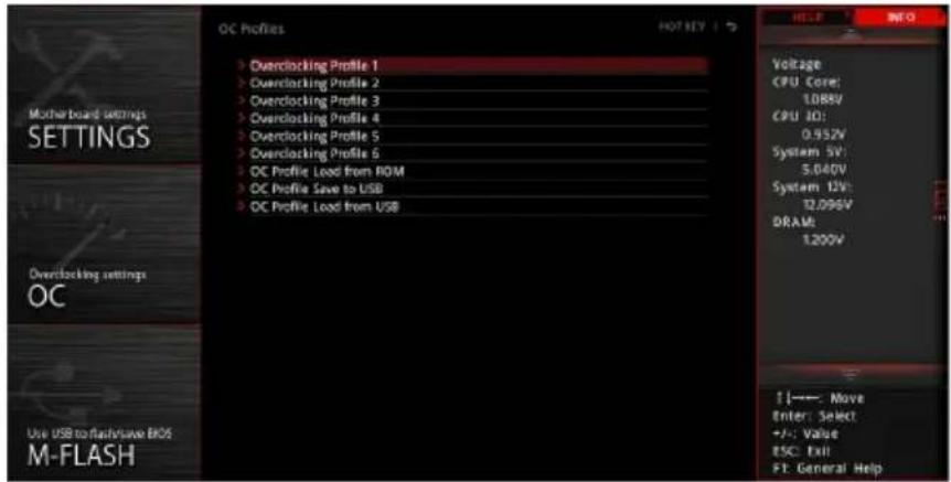
▶ Overclocking Profile 1/2/3/4/5/6
Overclocking Profile 1/2/3/4/5/6 management. Press to enter the sub-menu.
▶ Set Name for Overclocking Profile 1/2/3/4/5/6
Name the current overclocking profile.
▶ Save Overclocking Profile 1/2/3/4/5/6
Save the current overclocking profile.
▶ Load Overclocking Profile 1/2/3/4/5/6
Load the current overclocking profile.
▶ Clear Overclocking Profile 1/2/3/4/5/6
Clear the current overclocking profile.
▶ OC Profile Load from ROM
Load OC profile from BIOS ROM.
▶ OC Profile Save to USB
Save OC profile to the USB flash drive. The USB flash drive should be FAT/FAT32 format only.
▶ OC Profile Load from USB
Load OC profile from the USB flash drive. The USB flash drive should be FAT/FAT32 format only.
HARDWARE MONITOR

▶ Temperature & Speed
Shows the current CPU temperature, system temperature and fans' speeds.
▶ Fan Manage
- PWM - allows you to select the PWM mode for fan operation.
- DC - allows you to select the DC mode for fan operation.
- Fan step up/down time - allows you to set the period of fan step up/down.
- Smart Fan Mode field - allows you to drag the gradient points to configure the fan target values for Smart Fan mode. Smart Fan can control the fan speed automatically depending on the CPU temperature to keep it within a specific range. If the current CPU temperature reaches the target value, the Smart Fan function will be activated.

Important
The changes will take effect after you save the changes and reboot the system.
Make sure fans are working properly after switching the PWM/DC mode.
▶ Settings Buttons
- All Full Speed - configures all fans to run at full operating speed.
- All Set Default - configures all fans to run at default operating speed.
- All Set Cancel - discards current changes and restores previous operating fan speeds.
▶ Temperature/Voltage display
Shows CPU/system temperature and the current voltages of CPU, system, and memory.
RAID Configuration
Below are the different types of RAID.
RAID 0 breaks the data into blocks which are written to separate hard drives. Spreading the hard drive I/O load across independent channels greatly improves I/O performance.
RAID 1 provides data redundancy by mirroring data between the hard drives and provides enhanced read performance.
RAID 5 provides data striping at the byte level and also stripe error correction information. This results in excellent performance and good fault tolerance.
RAID 10 uses four hard drives to create a combination of RAID 0 and 1 by forming a RAID 0 array from two RAID 1 arrays.
RAID level comparison
| RAID 0 RAID 1 RAID 5 RAID 10 | ||||
| Minimum # drives 2 | 234 | |||
| Data protection None | Excellent Excellent | Excellent | ||
| Read performance | Excellent OK Good OK | |||
| Write performance | Excellent Good OK Good | |||
| Capacity utilization 1 | 100% 50% | 67%~(1-1/n) | 50% | |
Important
All the information/volumes/pictures listed in your system might differ from the illustrations in this appendix.
Enabling Intel® Rapid Storage Technology
In Legacy mode, we can change the AHCI mode to RAID mode and disable the Fast Boot then press Ctrl + I during the POST to enter the Intel Rapid Storage Technology Legacy mode. However, most newer version of operating systems support UEFI and the Intel Rapid Storage Technology UEFI mode can still run when the Fast Boot is enabled. Therefore we recommend that you use the UEFI BIOS for simple and advanced operations. The following description is based on the UEFI mode.
To enter the Intel(R) Rapid Storage Technology menu
- Power on and press Delete key to enter BIOS Setup menu.
- Press F7 to switch to Advanced mode from EZ mode.
- Go to BIOS > SETTINGS > Advanced > Integrated Peripherals > SATA Mode and change setting to RAID/ Optane Mode.
- Go to BIOS > SETTINGS > Advanced > Windows OS Configuration > Windows 10 WHQL Support and change setting to Enabled.
- Skip this step If you are only using SATA storage devices. If you are using NVMe PCIe SSDs, go to BIOS > SETTINGS > Advanced > Integrated Peripherals > M2_X Pcie Storage Remapping and change setting to Enabled.
- Press F10 to save configuration and exit, and then reboot and press Delete key to enter BIOS Setup menu.
- Go to BIOS > SETTING > Advanced > Intel(R) Rapid Storage Technology sub-menu.
Creating RAID Volume
- As previously mentioned, enable Intel(R) Rapid Storage Technology.

- Enter Create RAID Volume screen. The following screen appears:
![Settings > Advanced > Intel(R) Rapid Storage Technology > Create RAID Volume. Create RAID Volume. Name: Volume Name. RAID Level: [RAID1 (Mirror)]. Select Disks: SATA 0.0, ST1000DM010-2EP102 Z9ASRBHF, 93 [X]; SATA 0.1, ST1000DM010-2EP102 Z9ASEE7C, 931 [X]; PCIe 1.0, INTEL SSDPEKKW128G8 BTHH75130G [ ]…](/content/2026/06/1350721/images/20e38df9301e74cdd59c1508f52bda98d42f62f8f47396c76e59fca9e1bd61d4.jpg)
- Specify a Name for RAID volume.
- Select the RAID Level best suited to your usage model in RAID Level.
- In the Select Disks field, press Space key or press Enter key and use the ↑ ↓ arrow keys to select the option X to select the disks you want to create for the RAID volume.
- Select the Strip Size for the RAID array. The available values range from 4KB to 128 KB in power of 2 increments. The strip size should be chosen based on the planned drive usage. Here are some typical values: RAID0 -128KB / RAID10 - 64KB / RAID5 - 64KB.
- Select the capacity of the volume in the Capacity (MB) field. The default value is the maximum volume capacity of the selected disks.
- Go to the Create Volume field and press Enter to create the RAID volume. Upon completion you are returned to the Intel(R) Rapid Storage Technology menu.
Removing a RAID Volume
Here you can delete the RAID volume, but please be noted that all data on RAID drives will be lost.
Important
If your system currently boots to RAID and you delete the RAID volume, your system will become unbootable.
- Go to BIOS > SETTING > Advanced > Intel(R) Rapid Storage Technology.
- Select the RAID volume from the Intel(R) Rapid Storage Technology screen to enter the RAID VOLUME INFO screen.

- Select the Delete item and press Enter key to delete the selected RAID volume. The following screen appears:

- Select the Yes item and press Enter key to accept the volume deletion.
Resetting Disks to Non-RAID
- Go to BIOS > SETTING > Advanced > Intel(R) Rapid Storage Technology.
- Select the RAID volume from the Intel(R) Rapid Storage Technology screen to enter the RAID VOLUME INFO screen.
- Select the disk and press Enter to enter PHYSICAL DISK INFO screen.
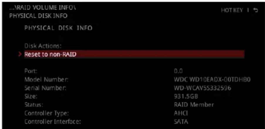
- Select Reset to non-RAID item and press Enter to delete the RAID volume and remove any RAID structures from the drives. The following screen appears:

- Select the Yes item and press Enter key to accept the disk resetting.

Important
You will lose all data on the RAID drives and any internal RAID structures when you perform this operation.
Possible reasons to Reset Disks to Non-RAID could include issues such as incompatible RAID configurations or a failed volume or failed disk.
Rebuilding RAID Array
A RAID 1, RAID 5 or RAID 10 volume is reported as Degraded when one of its hard drive members fails or is temporarily disconnected, and data mirroring is lost. As a result, the system can only utilize the remaining functional hard drive member. To re-establish data mirroring and restore data redundancy, refer to the procedure below that corresponds to the current situation.
- Power off.
- Replace the failed hard drive with a new one that is of equal or greater capacity.
- Reboot the system and go to BIOS > SETTING > Advanced > Intel(R) Rapid Storage Technology.

- Select the Degraded RAID volume from the Intel(R) Rapid Storage Technology screen to enter the RAID VOLUME INFO screen.

- Select the Rebuild item and press Enter key to rebuild the new hard drive.
Installing RAID Driver
New Operating System Installation
The following details the installation of the drivers while installing Windows 10 x64 bit Editions or newer operating system.
- During the operating system installation, after selecting the location to install Windows click on Load driver button to install a third party RAID driver.
- When prompted, insert the USB flash drive with Intel RAID Drivers and then click Browse.
- To make an Intel RAID Drivers USB flash drive. Insert the MSI Driver Disc into the optical drive. Copy all the contents in \Storage\Intel\16.x\f6flpy-x64
- Navigate to the directory containing the saved Intel RAID drivers, then click OK.
- Select the (iaStorAC.inf) driver, click Next.
- You have successfully installed the RAID driver, and Windows setup should continue.
- Leave the disk/USB drive in the computer until the system reboots itself. Windows setup will need to copy the files after the RAID volume is formatted, and Windows setup starts copying files.
Installing Intel® Rapid Storage Technology Software
- As previously mentioned, enable Intel(R) Rapid Storage Technology in BIOS.
- Insert the MSI Driver Disc into the optical drive.
- Click the Select to choose what happens with this disc pop-up notification, then select Run DVDSetup.exe to open the installer. If you turn off the AutoPlay feature from the Windows Control Panel, you can still manually execute the DVDSetup.exe from the root path of the MSI Driver Disc.
- Under the Drivers/Software tab, check the Intel RAID Drivers check-box.
- Click the Install button.
- When prompt you to restart, click OK button to finish.
- Restart your computer and enter the Windows operating system.
- Double-click the Intel® Rapid Storage Technology icon to open the Intel® Rapid Storage Technology software.
Intel® Optane™ Memory Configuration
Intel® Optane™ memory can accelerate the Windows 10 64-bit operating system. This section describes how to install and remove the Intel® Optane™ memory.
System Requirements
- Intel® Optane™ memory ready MSI® motherboards
- Supported 8th Gen, or later, Intel® Core™ i Processor
- System BIOS that supports the Intel® Rapid Storage Technology (Intel® RST) 16 or later driver
- Operating system: Windows 10 64-bit (UEFI mode).
- Intel® Optane™ Memory Module
Installing the Intel® Optane™ memory
Install the Intel® Rapid Storage Technology 16.
- Update BIOS (refer to the Updating BIOS section).
- Install the Intel® Optane™ memory module.
• Power off the system.
- Refer to the Specifications for the location to install your Intel® Optane™ memory module.
• Install the Intel® Optane™ memory module into the M.2 slot.
- Enable M.2/Optane Genie
• Power on and press the Delete key to enter the BIOS Setup menu.
- Enable M.2/Optane Genie by clicking the M.2/Optane Genie item.
- Click OK in the dialog.
- Press F10 to save configuration and exit.
- Install the Intel® Rapid Storage Technology
• Reboot to the operating system.
- Insert the MSI Driver Disc into the optical drive.
- Click the "Select to choose what happens with this disc" pop-up notification, then select "Run DVDSetup.exe" to open the installer. If you turn off the AutoPlay feature from the Windows Control Panel, you can still manually execute the DVDSetup.exe from the root path of the MSI Driver Disc.
• Under the Drivers/Software tab, check the Intel RAID Drivers check-box.
- Click the Install button.
- When prompted to restart, click OK to finish.
- Reboot the system.
- Enable Intel® Optane™ Memory.
- Run the Intel Rapid Storage Technology software.
- Click the Intel Optane™ Memory tab and click Enable.
- Click Yes in the dialog.

- Reboot the system.

WARNING
Once you enable Intel® Optane™ memory, to prevent serious damage to your operating system, please follow the cautions listed below.
DO NOT set the SATA mode back to AHCI in BIOS.
DO NOT revert to an older version of the BIOS.
DO NOT remove the Intel® Optane™ memory module.
DO NOT replace the CPU that is not supported by Intel® Optane™ Memory.
Removing the Intel® Optane™ memory
If you no longer want to use Intel® Optane™ memory, you have to disable the Intel® Optane™ memory before removing the Intel® Optane™ memory module to avoid operating system damage. Please follow the steps below to remove the Intel® Optane™ memory.
- Disable Intel® Optane™ Memory.
- Disable Intel® Optane™ Memory via the Intel® Optane™ memory application (Intel® Rapid Storage Technology).
- Click Yes in the dialog.
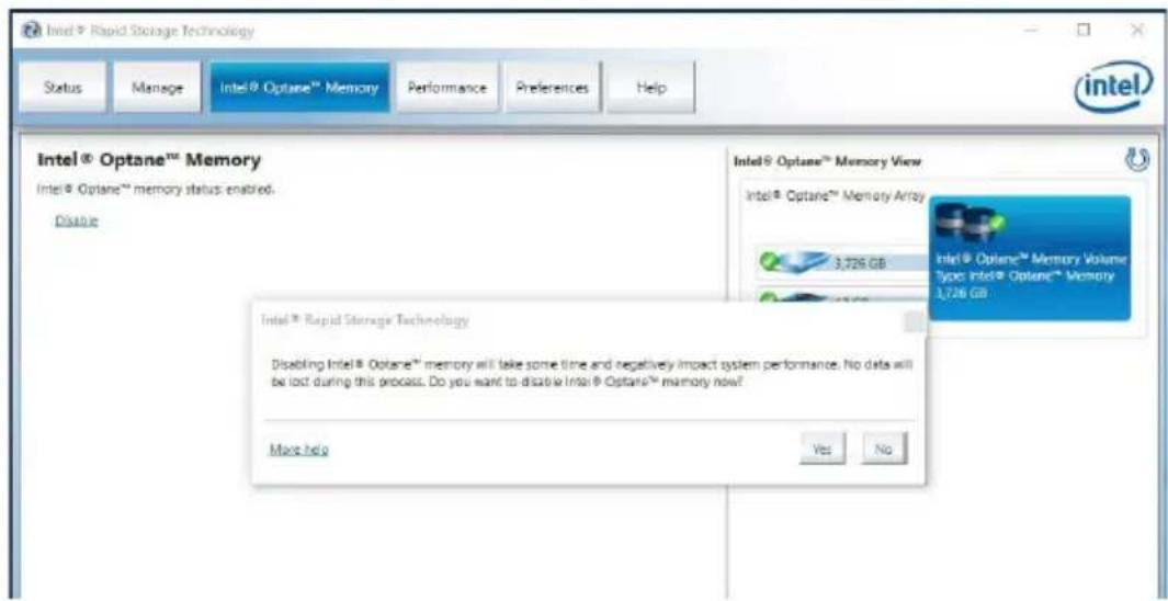
- Reboot System.
- Disable M.2/Optane Genie
- Press Delete key to enter BIOS Setup menu during POST.
- Disable M.2/Optane Genie by clicking M.2/Optane Genie item.
- Click OK in the dialog.
- Press F10 to save configuration and exit.
- Remove the Intel® Optane™ memory module.
• Power off the system.
- Remove the Intel® Optane™ memory module.
Troubleshooting
Before sending the motherboard for RMA repair, try to go through the troubleshooting guide first to see if you have similar symptoms as mentioned below.
The power is not on.
Connect the AC power cord to an electrical outlet securely.
Check if all ATX power connectors like ATX_PWR1, CPU_PWR1 are connected from the power supply to the motherboard.
Some power supply units have a power button on the rear side, make sure the button is turned on.
Check if the power switch cable is connected to JFP1 pin header properly.
Verify the Clear CMOS jumper JBAT1 is set to Keep DATA.
Test with another known working power supply of equal or greater wattage.
The power is on, but no signal to monitor
Connect the monitor power cord to an electrical outlet securely.
Make sure the monitor is turned on.
Select different inputs on the monitor.
If 3 long beeps are heard, remove all memory modules and try to install only one memory module in the DIMMC1 slot first and then restart the computer.
If 1 long 2 short beeps are heard, remove and reinstall the graphics card and then restart the computer.
Test with another known working graphics card.
The computer does not boot after updating the BIOS
Clear the CMOS.
Use the secondary BIOS to boot up the system (Only for motherboards with Dual BIOS)
Lost BIOS password
Clear the CMOS, but that will cause you to lose all customized settings in the BIOS.
There is no audio
Connect the speakers/headphones to audio ports on the motherboard rear panel.
Remove secondary speakers/headphones, HDMI cables, USB audio devices.
Test with another known working speaker or headphone.
There is no network
Make sure the network chipset driver has been installed.
Verify if the network cable is properly connected and make sure the LAN port LEDs are properly illuminated.
Verify your TCP/IP settings.
Restart or reset your router.
Test with another known working LAN cable.
The USB device is not working
Make sure your USB drive driver has been installed.
Verify if USB device is listed in Windows® Device Manager.
Connect the USB device to other USB port on the motherboard rear I/O panel.
Regulatory Notices
FCC Compliance Statement
Note: This equipment has been tested and found to comply with the limits for a Class B digital device, pursuant to part 15 of the FCC Rules. These limits are designed to provide reasonable protection against harmful interference in a residential installation. This equipment generates, uses and can radiate radio frequency energy and, if not installed and used in accordance with the instructions, may cause harmful interference to radio communications. However, there is no guarantee that interference will not occur in a particular installation. If this equipment does cause harmful interference to radio or television reception, which can be determined by turning the equipment off and on, the user is encouraged to try to correct the interference by one or more of the following measures:
• Reorient or relocate the receiving antenna. - Increase the separation between the equipment and receiver. - Connect the equipment into an outlet on a circuit different from that to which the receiver is connected. - Consult the dealer or an experienced radio/TV technician for help.
Caution: Changes or modifications not expressly approved by the party responsible for compliance could void the user's authority to operate the equipment.

Tested to comply with FCC standards FOR HOME OR OFFICE USE
This device complies with part 15 of the FCC Rules. Operation is subject to the following two conditions: (1) This device may not cause harmful interference, and (2) this device must accept any interference received, including interference that may cause undesired operation.
CE Conformity

Products bearing the CE marking comply with one or more of the following EU Directives as may be applicable:
RED 2014/53/EU; Low Voltage Directive 2014/35/EU; EMC Directive 2014/30/EU; RoHS Directive 2011/65/EU. Compliance with these directives is assessed using applicable European Harmonized Standards. The point of contact for regulatory matters is MSI, MSI-NL Eindhoven 5706 5692 ER Son.
Class B equipment (household broadcasting and telecommunications equipment)

Batteries, battery packs, and accumulators should not be disposed of as unsorted household waste. Please use the public collection system to return, recycle, or treat them in compliance with the local regulations.
Taiwan:

Waste batteries should be recycled.
For better environmental protection, waste batteries should be collected separately for recycling or special disposal.
California, USA:

The button cell battery may contain perchlorate material and requires special handling when recycled or disposed of in California.
For further information please visit: http://www.dtsc.ca.gov/hazardouswaste/perchlorate/
CAUTION: There is a risk of explosion, if battery is incorrectly replaced. Replace only with the same or equivalent type recommended by the manufacturer.
Chemical Substances Information
In compliance with chemical substances regulations, such as the EU REACH Regulation (Regulation EC No. 1907/2006 of the European Parliament and the Council), MSI provides the information of chemical substances in products at: http://www.msi.com/html/popup/csr/evmtprtt_pcm.html
Environmental Policy
- The product has been designed to enable proper reuse of parts and recycling and should not be thrown away at its end of life.
- Users should contact the local authorized point of collection for recycling and disposing of their end-of-life products.
- Visit the MSI website and locate a nearby distributor for further recycling information.
- Users may also reach us at gpcontdev@msi.com for information regarding proper disposal, take-back, recycling, and disassembly of MSI products.
WEEE (Waste Electrical and Electronic Equipment) Statement
ENGLISH
To protect the global environment and as an environmentalist, MSI must remind you that...
Under the European Union ("EU") Directive on Waste Electrical and Electronic
Equipment, Directive 2002/96/EC, which takes effect on August 13, 2005, products
of "electrical and electronic equipment" cannot


be discarded as municipal wastes anymore, and manufacturers of covered electronic equipment will be obligated to take back such products at the end of their useful life. MSI will comply with the product take back requirements at the end of life of MSI-branded products that are sold into the EU. You can return these products to local collection points.
DEUTSCH
This product complies with the "India E-waste (Management and Handling) Rule 2011" and prohibits use of lead, mercury, hexavalent chromium, polybrominated biphenyls or polybrominated diphenyl ethers in concentrations exceeding 0.1 weight % and 0.01 weight % for cadmium, except for the exemptions set in Schedule 2 of the Rule.
This device is restricted to indoor use when operating in the 2.4GHz, 5GHz frequency band.
Products with radio functionality (EMF)
This product incorporates a radio transmitting and receiving device. For computers in normal use, a separation distance of 20 cm ensures that radio frequency exposure levels comply with EU requirements. Products designed to be operated at closer proximities, such as tablet computers, comply with applicable EU requirements in typical operating positions. Products can be operated without maintaining a separation distance unless otherwise indicated in instructions specific to the product.
Restrictions for products with radio functionality

CAUTION: IEEE 802.11x wireless LAN with 5.15–5.35 GHz frequency band is restricted for indoor use only in all European Union member states, EFTA (Iceland, Norway,
Liechtenstein), and most other European countries (e.g., Switzerland, Turkey, Republic of Serbia). Using this WLAN application outdoors might lead to interference issues with existing radio services.
Radio frequency bands and maximum power levels
Features: 802.11 a/b/g/n/ac, BT
Frequency Range: 2.4GHz, 5GHz
Modulation: FHSS, DSSS, OFDM
Power Output: 10, 20, 23
Channel Band Width: 1, 5, 20, 40, 80MHz
Copyright © 2018 All rights reserved.
Revision History
Version 1.0, 2018/10, First release
The MSI logo used is a registered trademark of Micro-Star Int'l Co., Ltd. All other marks and names mentioned may be trademarks of their respective owners. No warranty as to accuracy or completeness is expressed or implied. MSI reserves the right to make changes to this document without prior notice.
Technical Support
If a problem arises with your system and no solution can be obtained from the user guide, please contact your place of purchase or local distributor. Alternatively, please try the following help resources for further guidance.
- Visit the MSI website for technical guide, BIOS updates, driver updates, and other information: http://www.msi.com
- Register your product at: http://register.msi.com
- PREPARING TOOLS AND COMPONENTS
- SAFETY INFORMATION
- INSTALLING DDR4 MEMORY
- CONNECTING THE FRONT PANEL HEADER
- INSTALLING SATA DRIVES
- INSTALLING A GRAPHICS CARD
- CONNECTING THE POWER CONNECTORS
- CONTENTS
- QUICK START
- SPECIFICATIONS
- PACKAGE CONTENTS
- BLOCK DIAGRAM
- REAR I/O PANEL
- OVERVIEW OF COMPONENTS
- ONBOARD LEDS
- INSTALLING OS, DRIVERS & UTILITIES
- MYSTIC LIGHT
- NAHIMIC
- BIOS SETUP
- RAID CONFIGURATION
- INTEL® OPTANE™ MEMORY CONFIGURATION
- TROUBLESHOOTING
- THUNDERBOLT 3 CARD SPECIFICATION
- JCORSAIR1 CONNECTOR SPECIFICATION
- IMPORTANT
- REALTEK AUDIO CONSOLE
- AUTO POPUP DIALOG
- INSTALLING ANTENNAS
- CPU SOCKET
- MEMORY MODULE INSTALLATION RECOMMENDATION (2-CHANNELS ARCHITECTURE CPU)
- PCI_E1\~5: PCIE EXPANSION SLOTS
- PCIE AND M2_3 SLOT BANDWIDTH TABLE
- MULTIPLE GRAPHICS CARDS INSTALLATION RECOMMENDATION
- INSTALLING SLI GRAPHICS CARDS
- U2_1: U.2 CONNECTOR
- VIDEO DEMONSTRATION
- INSTALLING U.2 SSD
- M2_1~3: M.2 SLOTS (KEY M)
- INSTALLING M.2 MODULE
- USING M.2 SHIELD FROZR
- INSTALLING M.2 XPANDER-AERO CARD
- SATA1\~8: SATA 6GB/S CONNECTORS
- VRAID1: VIRTUAL RAID ON CPU CONNECTOR
- JFP1, JFP2: FRONT PANEL CONNECTORS
- JAUD1: FRONT AUDIO CONNECTOR
- CPU_PWR1\~3, ATX_PWR1, PCIE_PWR1: POWER CONNECTORS
- OC1: GAME BOOST KNOB
- USING GAME BOOST KNOB
- OC_RT1: OC RETRY JUMPER
- OC_FS1: OC FORCE ENTER BIOS JUMPER
- JSLOW1: SLOW MODE BOOTING JUMPER
- CPU_FAN1, PUMP_FAN1, SYS_FAN1~4, EXS_FAN1~2: FAN CONNECTORS
- W_FLOW1: WATER FLOW METER CONNECTOR
- T_SEN1: THERMAL SENSOR CONNECTOR
- JTBT1: THUNDERBOLT ADD-ON CARD CONNECTOR
- INSTALLING THUNDERBOLTM3 CARD
- JUSB3~4: USB 3.1 GEN1 CONNECTORS
- CHARGER PORT
- JUSB1~2: USB 2.0 CONNECTORS
- JUSB5: USB 3.1 GEN2 TYPE-C CONNECTOR
- POWER1, RESET1: POWER BUTTON, RESET BUTTON
- JBAT1: CLEAR CMOS (RESET BIOS) JUMPER
- RESETTING BIOS TO DEFAULT VALUES
- JCI1: CHASSIS INTRUSION CONNECTOR
- USING CHASSIS INTRUSION DETECTOR
- RESETTING THE CHASSIS INTRUSION WARNING
- BIOS_SW1: MULTI-BIOS SWITCH
- RECOVERING BIOS
- JRGB1, JRAINBOW1~2: RGB LED CONNECTORS
- CAUTION
- JCORSAIR1: CORSAIR CONNECTOR
- EZ DEBUG LED
- DIMM LEDS
- XMP LED
- MULTI-BIOS LEDS
- JPWRLED1: LED POWER INPUT
- DEBUG CODE LED
- HEXADECIMAL CHARACTER TABLE
- BOOT PHASES
- DEBUG CODE LED TABLE
- SEC PROGRESS CODES
- S3 RESUME PROGRESS CODES
- S3 RESUME ERROR CODES
- RECOVERY PROGRESS CODES
- RECOVERY ERROR CODES
- ACPI STATES CODES
- CPU TEMPERATURE
- INSTALLING WINDOWS
- INSTALLING DRIVERS
- INSTALLING UTILITIES
- DEVICE LED EFFECT CONTROL SCREEN
- INSTALLATION AND UPDATE
- AUDIO TAB
- MICROPHONE TAB
- SOUND TRACKER TAB
- SETTINGS TAB
- ENTERING BIOS SETUP
- FUNCTION KEY
- RESETTING BIOS
- UPDATING BIOS
- UPDATING BIOS WITH M-FLASH
- UPDATING THE BIOS WITH MSI DRAGON CENTER
- UPDATING BIOS WITH BIOS FLASHBACK
- EZ MODE
- ADVANCED MODE
- SETTINGS
- SYSTEM STATUS
- SYSTEM DATE
- SYSTEM TIME
- SATA PORTX/ M2_X
- SYSTEM INFORMATION
- DMI INFORMATION
- ADVANCED
- PCI SUBSYSTEM SETTINGS
- PEG X - MAX LINK SPEED [AUTO]
- ABOVE 4G MEMORY/ CRYPTO CURRENCY MINING [DISABLED]
- MMIO HIGH GRANULARITY SIZE [1G]
- VROC CONFIGURATION
- ACPI SETTINGS
- POWER LED [BLINKING]
- CPU OVER TEMPERATURE ALERT [AUTO]
- INTEGRATED PERIPHERALS
- ONBOARD LAN CONTROLLER [ENABLED]
- ONBOARD LAN CONTROLLER2 [ENABLED]
- LAN OPTION ROM [DISABLED]
- NETWORK STACK [DISABLED]
- IPV4 PXE SUPPORT [ENABLED]
- IPV6 PXE SUPPORT [ENABLED]
- SATA MODE [AHCI MODE]
- M2_X-RST PCIE STORAGE REMAPPING [DISABLED]
- M.2/OPTANE GENIE [DISABLED]
- SATAX HOT PLUG [DISABLED]
- HD AUDIO CONTROLLER [ENABLED]
- THUNDERBOLT(TM) CONFIGURATION
- DISCRETE THUNDERBOLT(TM) SUPPORT [DISABLED]
- USB CONFIGURATION
- USB CONTROLLER [ENABLED]
- XHCI HAND-OFF [DISABLED]
- LEGACY USB SUPPORT [ENABLED]
- POWER MANAGEMENT SETUP
- ERP READY [DISABLED]
- RESTORE AFTER AC POWER LOSS [POWER OFF]
- SYSTEM POWER FAULT PROTECTION [DISABLED]
- WINDOWS OS CONFIGURATION
- WINDOWS 10 WHQL SUPPORT [DISABLED]
- MSI FAST BOOT [DISABLED]
- FAST BOOT [ENABLED]
- INTERNAL GOP CONFIGURATION
- SECURE BOOT
- SECURE BOOT SUPPORT [DISABLED]
- SECURE BOOT MODE [STANDARD]
- KEY MANAGEMENT
- WAKE UP EVENT SETUP
- WAKE UP EVENT BY [BIOS]
- RESUME BY RTC ALARM [DISABLED]
- DATE (OF MONTH) ALARM/ TIME (HH:MM:SS) ALARM
- RESUME BY PCI-E DEVICE [DISABLED]
- RESUME BY ONBOARD INTEL LAN [DISABLED]
- RESUME BY USB DEVICE [DISABLED]
- RESUME FROM S3/S4/S5 BY PS/2 MOUSE [DISABLED]
- RESUME FROM S3/S4/S5 BY PS/2 KEYBOARD [DISABLED]
- HOT KEY [CTRL+SPACE]
- SECURE ERASE
- BOOT
- FULL SCREEN LOGO DISPLAY [ENABLED]
- GO2BIOS [DISABLED]
- BOOTUP NUMLOCK STATE [ON]
- INFO BLOCK EFFECT [UNLOCK]
- AUTO CLR_CMOS [DISABLED]
- BOOT MODE SELECT [LEGACY+UEFI]
- FIXED BOOT ORDER PRIORITIES
- BOOT OPTION PRIORITIES
- SECURITY
- ADMINISTRATOR PASSWORD
- USER PASSWORD
- PASSWORD CHECK [SETUP]
- PASSWORD CLEAR [ENABLED]
- TRUSTED COMPUTING
- SECURITY DEVICE SUPPORT [DISABLED]
- CHASSIS INTRUSION CONFIGURATION
- CHASSIS INTRUSION [DISABLED]
- SAVE & EXIT
- OC
- OC EXPLORE MODE [EXPERT]
- CPU RATIO APPLY MODE [ALL CORE]
- X-CORE RATIO LIMIT [AUTO]
- ADJUSTED CPU FREQUENCY
- CORE X X OF X XXXX MHZ [AUTO]
- CPU RATIO OFFSET WHEN RUNNING AVX [AUTO]
- GAME BOOST FUNCTION CONTROL [BY ONBOARD BUTTON]
- RING RATIO [AUTO]
- ADJUSTED RING FREQUENCY
- MISC SETTING
- EIST [ENABLED]
- INTEL TURBO BOOST [ENABLED]
- ENHANCED TURBO [AUTO]
- CPU BASE CLOCK (MHZ)
- CPU BASE CLOCK APPLY MODE [AUTO]
- CLOCKGEN FEATURES (OPTIONAL)
- DYNAMIC FREQUENCY CONTROL [DISABLED]
- DFC BASELINE (MHZ) [AUTO]
- THRESHOLD 1\~3 (A) [AUTO]
- LEVEL 1\~3 BCLK (MHZ) [AUTO]
- DYNAMIC FREQUENCY SEARCH [DISABLED]
- DYNAMIC FREQUENCY SEARCH MODE [ONCE]
- DYNAMIC FREQUENCY SEARCH STEP (MHZ) [AUTO]
- BCLK AMPLITUDE [AUTO]
- SRC CLOCK AMPLITUDE [AUTO]
- SATA CLOCK AMPLITUDE [AUTO]
- BCLK SLEW RATE [AUTO]
- BCLK ORT DURATION [AUTO]
- EXTREME MEMORY PROFILE (X.M.P.) [DISABLED]
- DRAM REFERENCE CLOCK [AUTO]
- DRAM FREQUENCY [AUTO]
- ADJUSTED DRAM FREQUENCY
- LOAD MEMORY PRESETS [DISABLED]
- MEMORY TRY IT ! [DISABLED]
- DRAM TIMING MODE [LINK]
- ADVANCED DRAM CONFIGURATION
- MEMORY FAST BOOT [AUTO]
- CPU VOLTAGES CONTROL [AUTO]
- DRAM VOLTAGES CONTROL [AUTO]
- CPU MEMORY CHANGED DETECT [ENABLED]
- OC QUICK VIEW TIMER [3 SEC]
- CPU SPECIFICATIONS
- CPU TECHNOLOGY SUPPORT
- MEMORY-Z
- DIMMA1/A2/B1/B2/C1/C2/D1/D2 MEMORY SPD
- CPU FEATURES
- HYPER-THREADING [ENABLED]
- ACTIVE PROCESSOR CORES CONTROL [ALL]
- LIMIT CPUID MAXIMUM [DISABLED]
- INTEL VIRTUALIZATION TECH [ENABLED]
- INTEL VT-D TECH [DISABLED]
- HARDWARE PREFETCHER [ENABLED]
- ADJACENT CACHE LINE PREFETCH [ENABLED]
- CPU AES INSTRUCTIONS [ENABLED]
- INTEL ADAPTIVE THERMAL MONITOR [ENABLED]
- INTEL C-STATE [AUTO]
- C1E SUPPORT [DISABLED]
- PACKAGE C STATE LIMIT [AUTO]
- CFG LOCK [ENABLED]
- LONG DURATION POWER LIMIT (W) [AUTO]
- LONG DURATION MAINTAINED (S) [AUTO]
- SHORT DURATION POWER LIMIT (W) [AUTO]
- CPU CURRENT LIMIT (A) [AUTO]
- INTERNAL VR OVP OCP PROTECTION [AUTO]
- INTERNAL VR EFFICIENCY MANAGEMENT [AUTO]
- M-FLASH
- OC PROFILE
- HARDWARE MONITOR
- TEMPERATURE & SPEED
- FAN MANAGE
- SETTINGS BUTTONS
- TEMPERATURE/VOLTAGE DISPLAY
- ENABLING INTEL® RAPID STORAGE TECHNOLOGY
- TO ENTER THE INTEL(R) RAPID STORAGE TECHNOLOGY MENU
- CREATING RAID VOLUME
- REMOVING A RAID VOLUME
- RESETTING DISKS TO NON-RAID
- REBUILDING RAID ARRAY
- INSTALLING RAID DRIVER
- NEW OPERATING SYSTEM INSTALLATION
- INSTALLING INTEL® RAPID STORAGE TECHNOLOGY SOFTWARE
- SYSTEM REQUIREMENTS
- INSTALLING THE INTEL® OPTANE™ MEMORY
- WARNING
- REMOVING THE INTEL® OPTANE™ MEMORY
- THE POWER IS NOT ON
- THE POWER IS ON, BUT NO SIGNAL TO MONITOR
- THE COMPUTER DOES NOT BOOT AFTER UPDATING THE BIOS
- LOST BIOS PASSWORD
- THERE IS NO AUDIO
- THERE IS NO NETWORK
- THE USB DEVICE IS NOT WORKING
- REGULATORY NOTICES
- FCC COMPLIANCE STATEMENT
- CE CONFORMITY
- CLASS B EQUIPMENT (HOUSEHOLD BROADCASTING AND TELECOMMUNICATIONS EQUIPMENT)
- CHEMICAL SUBSTANCES INFORMATION
- ENVIRONMENTAL POLICY
- WEEE (WASTE ELECTRICAL AND ELECTRONIC EQUIPMENT) STATEMENT
- DEUTSCH
- PRODUCTS WITH RADIO FUNCTIONALITY (EMF)
- RESTRICTIONS FOR PRODUCTS WITH RADIO FUNCTIONALITY
- RADIO FREQUENCY BANDS AND MAXIMUM POWER LEVELS
- REVISION HISTORY
- TECHNICAL SUPPORT
Brand : MSI
Model : MEG X299 Creation
Category : Motherboard