
H310M Pro - Motherboard MSI - Free user manual and instructions
Find the device manual for free H310M Pro MSI in PDF.
| Product Type | Motherboard |
| Brand | MSI |
| Model | H310M Pro |
| CPU Socket | LGA1151 |
| Chipset | Intel® H310 |
| Form Factor | m-ATX |
| Dimensions | 23.0 x 18.5 cm |
| Supported Processors | Intel® Core™, Pentium® Gold, and Celeron® 8th Gen |
| Memory | 2 x DDR4, max 32 GB, 2666/2400/2133 MHz, dual channel |
| Expansion Slots | 1 x PCIe 3.0 x16, 2 x PCIe 2.0 x1 |
| Storage | 4 x SATA 6 Gb/s, 1 x M.2 (M Key, PCIe 2.0 x4/SATA) |
| USB | 4 x USB 3.1 Gen1 (2 rear), 6 x USB 2.0 (4 rear) |
| Video Outputs | 1 x VGA, 1 x DVI-D, 1 x HDMI 1.4 |
| Audio | Realtek ALC887, 7.1 channels |
| Network | Intel I219-V Gigabit LAN |
| Power Connectors | ATX 24-pin, ATX 12V 8-pin |
| BIOS | UEFI AMI, 128 Mb flash |
| Special Features | EZ Debug LED, Clear CMOS, chassis intrusion detection |
| Security | TPM module support |
| Operating Temperature | Maximum 60°C |
| Maintenance and Cleaning | Avoid humidity and electrostatic discharge. Clean with a soft dry cloth. |
| Repairability | Standard motherboard, no specific spare parts provided. Replace the board if defective. |
Frequently Asked Questions - H310M Pro MSI
User questions about H310M Pro MSI
0 question about this device. Answer the ones you know or ask your own.
Ask a new question about this device
Download the instructions for your Motherboard in PDF format for free! Find your manual H310M Pro - MSI and take your electronic device back in hand. On this page are published all the documents necessary for the use of your device. H310M Pro by MSI.
USER MANUAL H310M Pro MSI
Thank you for purchasing the MSI® H310M PRO-M2 motherboard. This User Guide gives information about board layout, component overview, BIOS setup and software installation.
Contents
Safety Information 2
Specifications. 3
Rear I/O Panel 6
LAN Port LED Status Table. 6
Overview of Components 7
CPU Socket 8
DIMM Slots 9
PCI_E1~3:PCIe Expansion Slots 9
JFP1, JFP2: Front Panel Connectors 10
SATA1-4: SATA 6Gb/s Connectors. 10
M2_1: M.2 Slot (Key M) 11
ATX_PWR1, CPU_PWR1: Power Connectors. 11
JUSB1: USB 2.0 Connector 12
JUSB2: USB 3.1 Gen1 Connector 12
JAUD1: Front Audio Connector 13
JCOM1: Serial Port Connector 13
JTPM1: TPM Module Connector 13
CPU_FAN1, SYS_FAN1: Fan Connectors 14
EZ Debug LED 15
JCI1: Chassis Intrusion Connector 16
JBAT1: Clear CMOS (Reset BIOS) Jumper 16
BIOS Setup 17
EnteringBIOS Setup 17
ResettingBIOS 18
Updating BIOS. 18
Software Description 19
Installing Windows® 10 19
Installing Drivers 19
Installing Utilities 19
Safety Information
- The components included in this package are prone to damage from electrostatic discharge (ESD). Please adhere to the following instructions to ensure successful computer assembly.
- Ensure that all components are securely connected. Loose connections may cause the computer to not recognize a component or fail to start.
- Hold the motherboard by the edges to avoid touching sensitive components.
- It is recommended to wear an electrostatic discharge (ESD) wrist strap when handling the motherboard to prevent electrostatic damage. If an ESD wrist strap is not available, discharge yourself of static electricity by touching another metal object before handling the motherboard.
- Store the motherboard in an electrostatic shielding container or on an anti-static pad whenever the motherboard is not installed.
- Before turning on the computer, ensure that there are no loose screws or metal components on the motherboard or anywhere within the computer case.
- Do not boot the computer before installation is completed. This could cause permanent damage to the components as well as injury to the user.
- If you need help during any installation step, please consult a certified computer technician.
-
Always turn off the power supply and unplug the power cord from the power outlet before installing or removing any computer component.
-
Keep this user guide for future reference.
-
Keep this motherboard away from humidity.
-
Make sure that your electrical outlet provides the same voltage as is indicated on the PSU, before connecting the PSU to the electrical outlet.
- Place the power cord such a way that people can not step on it. Do not place anything over the power cord.
- All cautions and warnings on the motherboard should be noted.
- If any of the following situations arises, get the motherboard checked by service personnel:
Liquid has penetrated into the computer.
The motherboard has been exposed to moisture.
- The motherboard does not work well or you can not get it work according to user guide.
The motherboard has been dropped and damaged.
The motherboard has obvious sign of breakage.
- Do not leave this motherboard in an environment above 60^ [140^] , it may damage the motherboard.
Specifications
| CPU | Supports 8th Gen Intel® Core™, Pentium® Gold and Celeron® processors for Socket LGA1151 |
| Chipset Intel | ® H310 Chipset |
| Memory | 2x DDR4 memory slots, support up to 32GBSupports DDR4 2666/ 2400/ 2133 MHz MemorySupports Dual-Channel modeSupports non-ECC, un-buffered memorySupports IneXtreme Memory Profile (XMP)* Please refer www.msi.com for more information on compatible memory. |
| Expansion Slots | 1x PCIe 3.0 x16 slot2x PCIe 2.0 x1 slots |
| Onboard Graphics | 1x VGA port, supports a maximum resolution of 2048x1536@50Hz, 2048x1280@60Hz, 1920x1200@60Hz*1x DVI-D port, supports a maximum resolution of 1920x1200@60Hz*1x HDMI™ port 1.4, supports a maximum resolution of 4096x2160@30Hz**Supports up to 2 displays simultaneously |
| Storage | Intel® H310 Chipset4x SATA 6Gb/s ports*1x M.2 slot (Key M)Support up to PCIe 2.0 x4 and SATA 6Gb/sSupports 2242/ 2260 /2280 storage devices |
| USB | InteH310 Chipset4x USB 3.1 Gen1 (SuperSpeed USB) ports (2 Type-A ports on the back panel, 2 ports available through the internal USB connectors)6x USB 2.0 (High-speed USB) ports (4 Type-A ports on the back panel, 2 ports available through the internal USB connectors) |
| Audio | Realtek ALC887 Codec7.1-Channel High Definition Audio |
| LAN 1x Intel 1219-V | Gigabit LAN controller |
Continued on next page
Continued from previous page
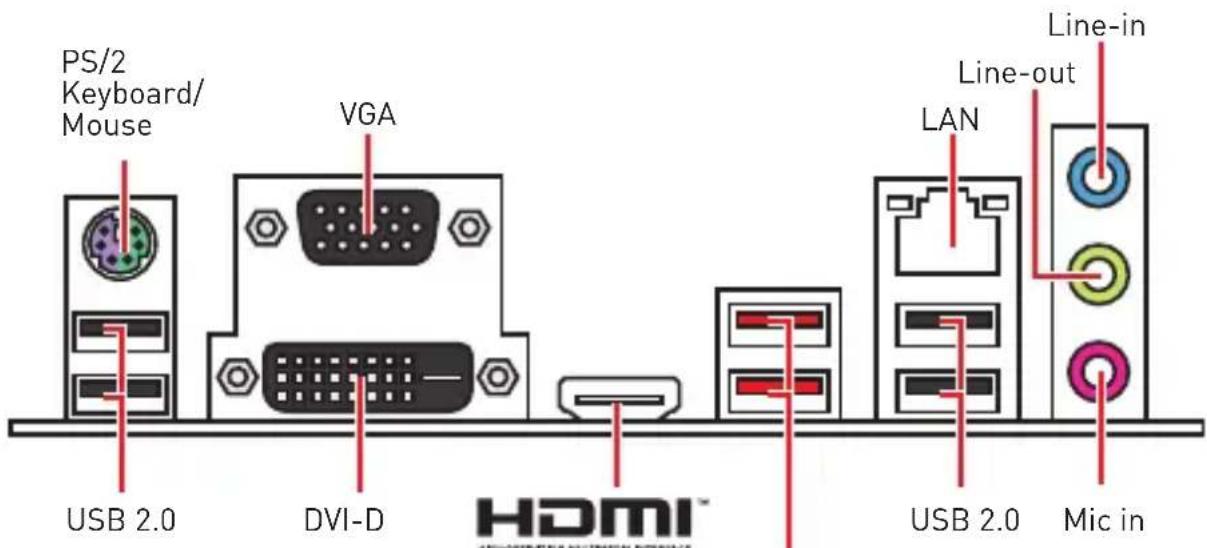
| Back Panel Connectors | • 1x PS/2 keyboard/ mouse combo port • 4x USB 2.0 Type-A ports • 1x VGA port • 1x DVI-D port • 1x HDMI™ port • 2x USB 3.1 Gen1 Type-A ports • 1x LAN (RJ45) port • 3x Audio jacks |
| Internal Connectors | • 1x 24-pin ATX main power connector • 1x 8-pin ATX 12V power connector • 4x SATA 6Gb/s connectors • 1x USB 3.1 Gen1 connector (supports additional 2 USB 3.1 Gen1 ports) • 1x USB 2.0 connector (supports additional 2 USB 2.0 ports) • 1x 4-pin CPU fan connector • 1x 4-pin system fan connector • 1x Front panel audio connector • 1x Serial port connector • 2x Front panel connectors • 1x TPM module connector • 1x Chassis Intrusion connector • 1x Clear CMOS jumper |
| I/O Controller NUVOTON NCT5567 Controller Chip | |
| Hardware Monitor | • CPU/System temperature detection • CPU/System fan speed detection • CPU/System fan speed control |
| Form Factor | • m-ATX Form Factor • 9.1 in. x 7.3 in. (23.0 cm x 18.5 cm) |
| BIOS Features | • 1x 128 Mb flash • UEFI AMI BIOS • ACPI 6.1, SM BIOS 2.8 • Multi-language |
Continued on next page
Continued from previous page
Software
- Drivers
- APP MANAGER
SUPER CHARGER
COMMANDCENTER - LIVE UPDATE 6
SMART TOOL - RAMDISK
DPC LATENCY TUNER - FAST BOOT
X-BOOST - NETWORK MANAGER
CPU-ZMSIGAMING - Extreme Tuning Utility
- Google Chrome™, Google Toolbar, Google Drive
NortonTM Internet Security Solution
Rear I/O Panel
USB 3.1 Gen1
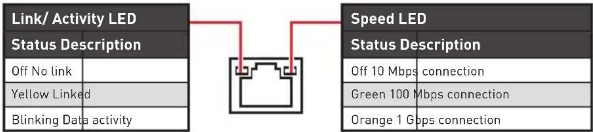
LAN Port LED Status Table
Audio 7.1-channel Configuration
To configure 7.1-channel audio, you have to connect front audio I/O module to JAUD1 connector and follow the below steps.
- Click on the Realtek HD Audio Manager > Advanced Settings to open the dialog below.

-
Select Mute the rear output device, when a front headphone plugged in.
-
Plug your speakers to audio jacks on rear and front I/O panel. When you plug into a device at an audio jack, a dialogue window will pop up asking you which device is current connected.
Overview of Components
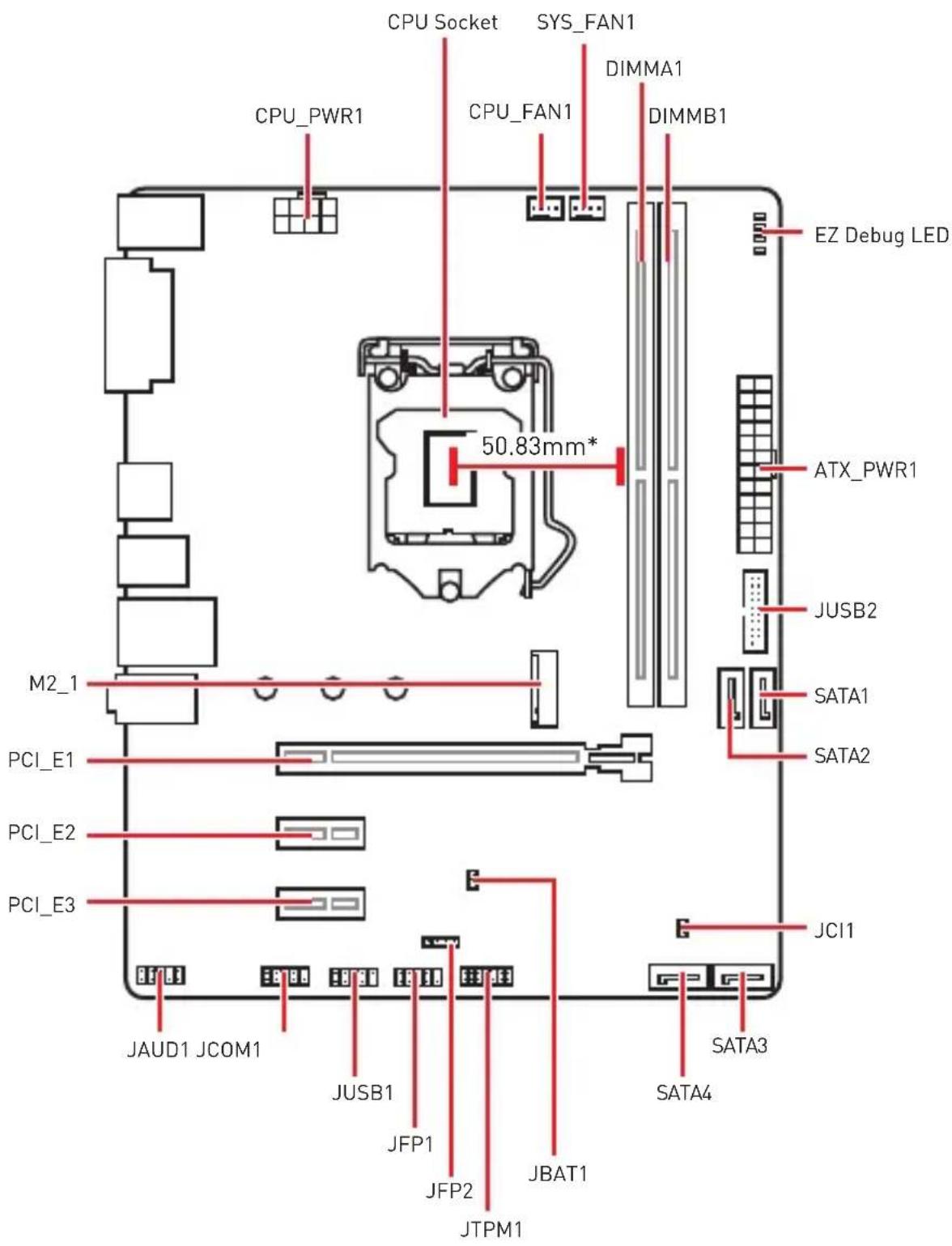
- Distance from the center of the CPU to the nearest DIMM slot.
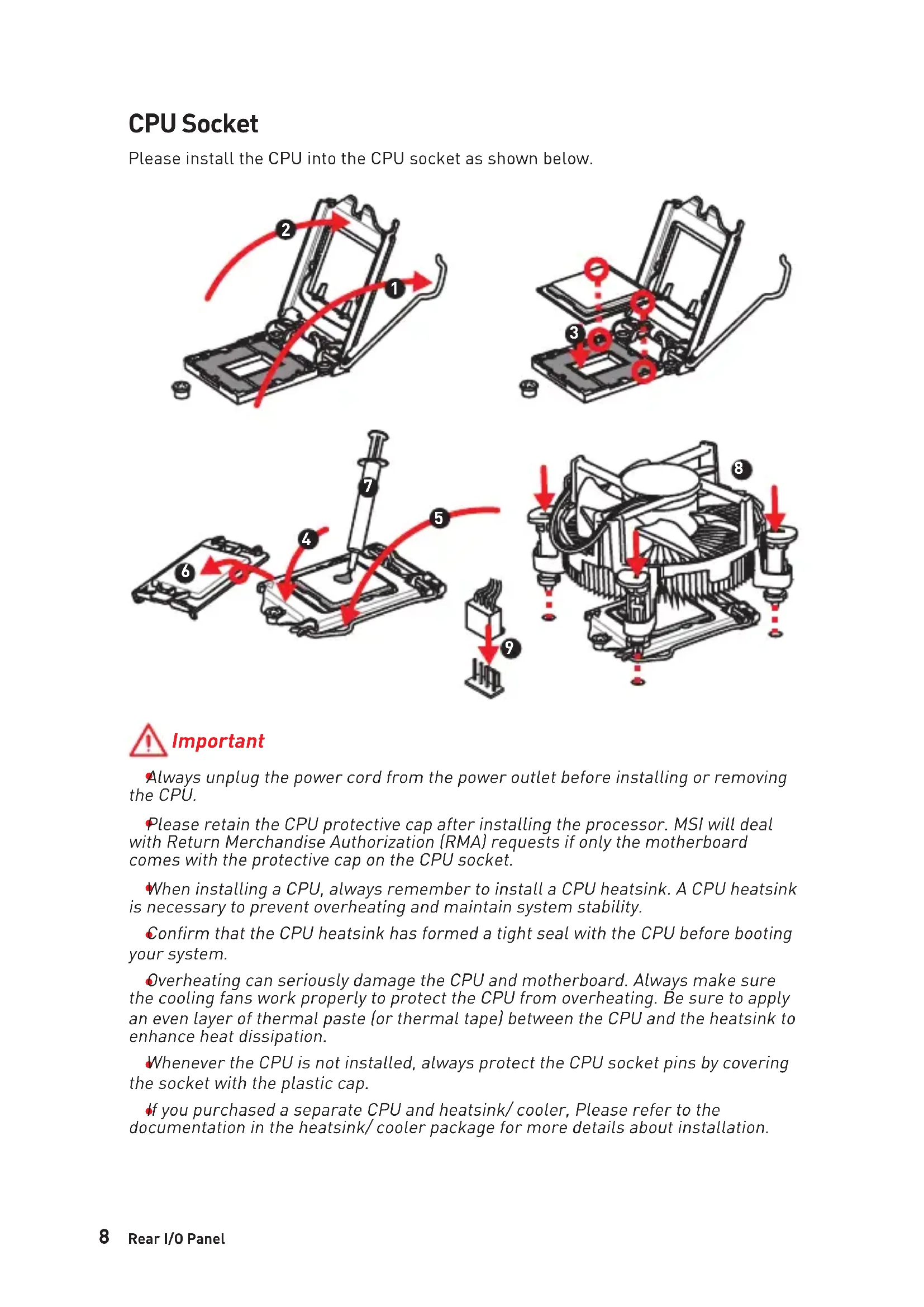
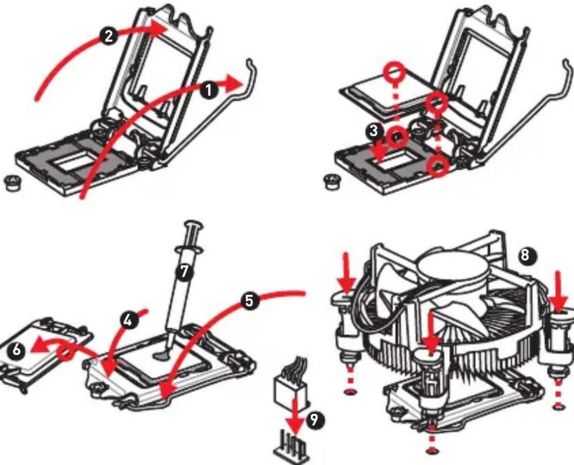
CPU Socket
Please install the CPU into the CPU socket as shown below.
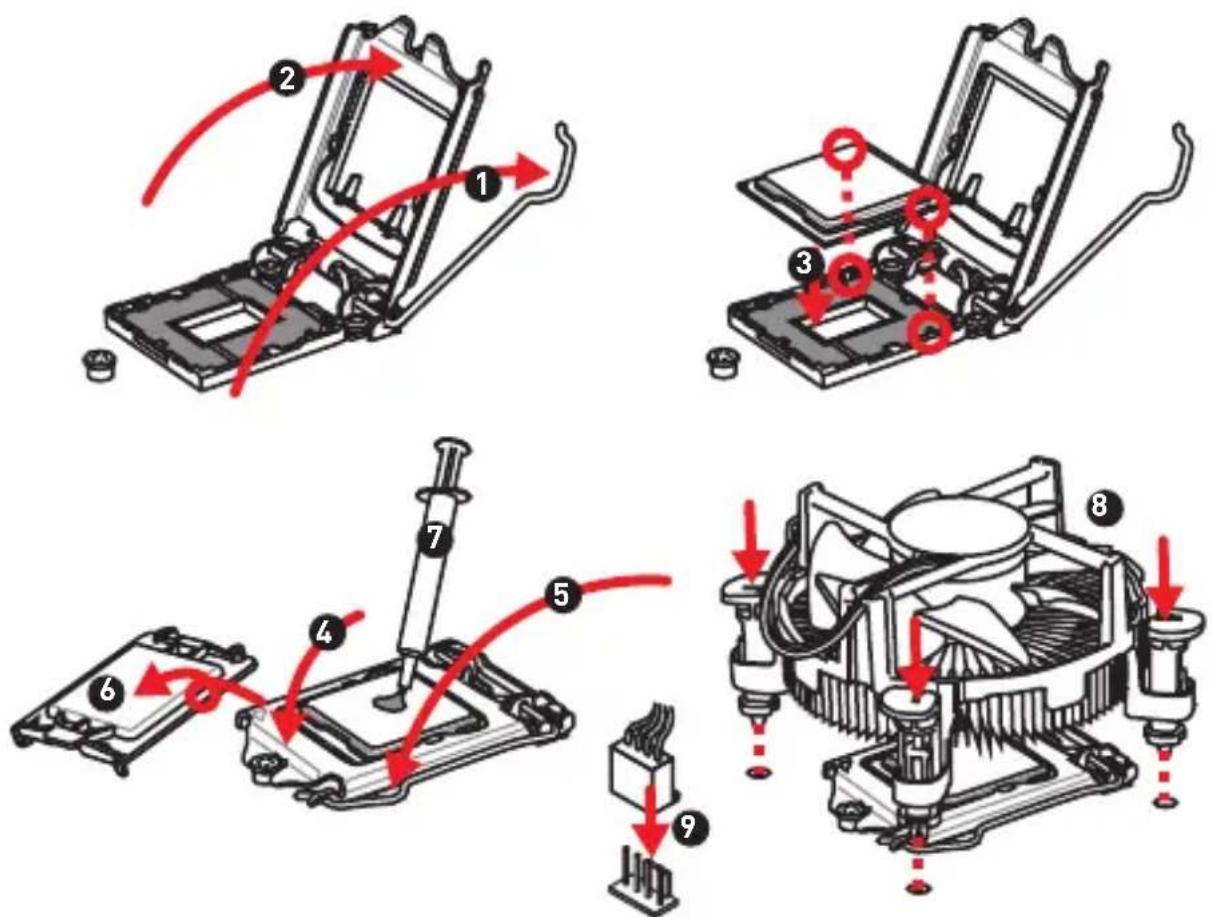

Important
Always unplug the power cord from the power outlet before installing or removing the CPU.
Please retain the CPU protective cap after installing the processor. MSI will deal with Return Merchandise Authorization (RMA) requests if only the motherboard comes with the protective cap on the CPU socket.
When installing a CPU, always remember to install a CPU heatsink. A CPU heatsink is necessary to prevent overheating and maintain system stability.
Confirm that the CPU heatsink has formed a tight seal with the CPU before booting your system.
Overheating can seriously damage the CPU and motherboard. Always make sure the cooling fans work properly to protect the CPU from overheating. Be sure to apply an even layer of thermal paste (or thermal tape) between the CPU and the heatsink to enhance heat dissipation.
Whenever the CPU is not installed, always protect the CPU socket pins by covering the socket with the plastic cap.
If you purchased a separate CPU and heatsink/ cooler, Please refer to the documentation in the heatsink/ cooler package for more details about installation.
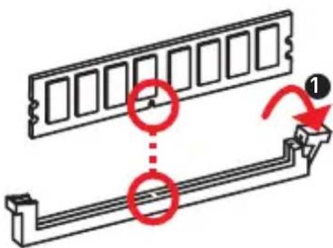
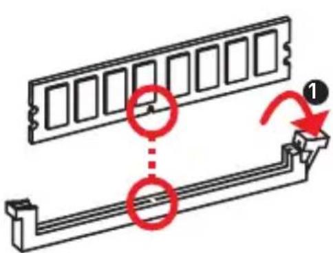
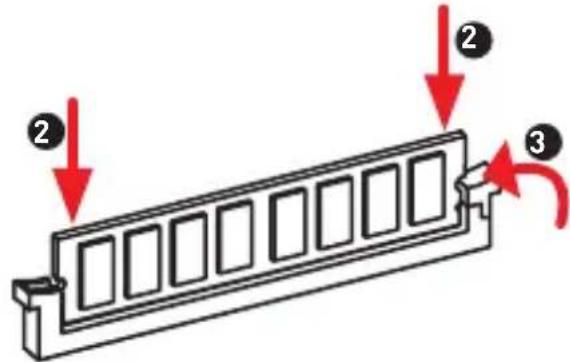
DIMM Slots
Please install the memory module into the DIMM slot as shown below.
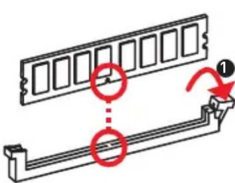


Important
To boot up the system successfully, always insert the memory module into DIMMA1 first.
Due to chipset resource usage, the available capacity of memory will be a little less than the amount of installed.
Please note that the maximum capacity of addressable memory is 4GB or less for 32-bit Windows OS due to the memory address limitation. Therefore, we recommended that you to install 64-bit Windows OS if you want to install more than 4GB memory on the motherboard.
PCI_E1~3: PCIe Expansion Slots
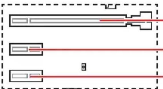
PCI_E1:PCIe 3.0 x16 (CPU lanes)
PCI_E2: PCIe 2.0 x1 (PCH lanes)
PCI_E3: PCIe 2.0 x1 (PCH lanes)

Important
If you install a large and heavy graphics card, you need to use a tool such as MSI Gaming Series Graphics Card Bolster to support its weight to prevent deformation of the slot.
When adding or removing expansion cards, always turn off the power supply and unplug the power supply power cable from the power outlet. Read the expansion card's documentation to check for any necessary additional hardware or software changes.
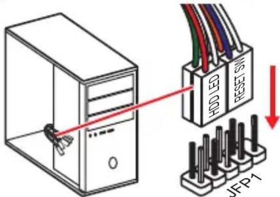
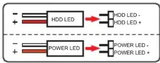
JFP1, JFP2: Front Panel Connectors
These connectors connect to the switches and LEDs on the front panel.
| JFP1 2 10 1 9 | 1 H | DD LED + 2 Power LED | + | |
| 3 H | DD LED - 4 Power LED | - | ||
| 5 Reset Switch 6 Power Switch | ||||
| 7 Reset Switch 8 Power Switch | ||||
| 9 Reserved 10 No Pin | ||||
| 1 JFP2 | 1 S | speaker - 2 Buzzer + | ||
| 3 | Buzzer - | 4 S | speaker + |
SATA1~4: SATA 6Gb/s Connectors
These connectors are SATA 6Gb/s interface ports. Each connector can connect to one SATA device.
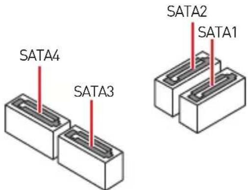

Important
Please do not fold the SATA cable at a 90-degree angle. Data loss may result during transmission otherwise.
- SATA cables have identical plugs on either sides of the cable. However, it is recommended that the flat connector be connected to the motherboard for space saving purposes.
M2_1: M.2 Slot (Key M)
Please install the M.2 solid-state drive (SSD) into the M.2 slot as shown below.
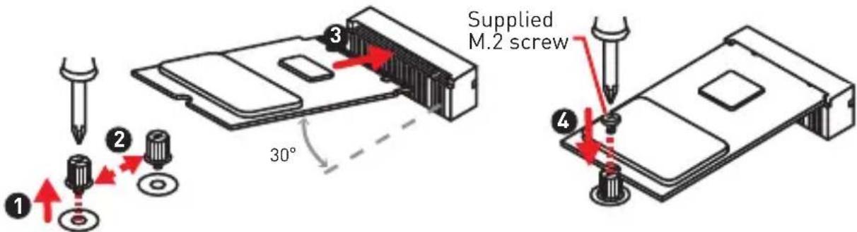

Intel® RST only supports PCIe M.2 SSD with UEFI ROM.
ATX_PWR1, CPU_PWR1: Power Connectors
These connectors allow you to connect an ATX power supply.
| 12 24 1 13 ATX_PWR1 | 1 + 3.3V 13 +3.3V | ||
| 2 + 3.3V 14 -12V | |||
| 3 Ground 15 Ground | |||
| 4 +5V 16 PS-ON# | |||
| 5 Ground 17 Ground | |||
| 6 +5V 18 Ground | |||
| 7 Ground 19 Ground | |||
| 8 PWR OK 20 Res | |||
| 9 5 VSB 21 +5V | |||
| 10 + 12V 22 +5V | |||
| 11 + 12V 23 +5V | |||
| 12 + 3.3V 24 Ground |
| CPU_PWR1 | 1 Ground 5 +12V | ||
| 2 Ground 6 +12V | |||
| 3 Ground 7 +12V | |||
| 4 Ground 8 +12V |

Make sure that all the power cables are securely connected to a proper ATX power supply to ensure stable operation of the motherboard.
JUSB1: USB 2.0 Connector
This connector allows you to connect USB 2.0 ports on the front panel.
| 2 10 1 9 | 1 VCC 2 VCC | ||
| 3 USB0- 4 USB1- | |||
| 5 USB0+ 6 USB1+ | |||
| 7 Ground 8 Ground | |||
| 9 No Pin 10 | NC |
Important
- Note that the VCC and Ground pins must be connected correctly to avoid possible damage.
- In order to recharge your iPad,iPhone and iPod through USB ports, please install MSI® SUPER CHARGER utility.
JUSB2: USB 3.1 Gen1 Connector
These connectors allow you to connect USB 3.1 Gen1 ports on the front panel.
| 10 11 1 20 | 1 Power 11 USB2.0+ | ||
| 2 USB3_RX_DN 12 USB2.0- | |||
| 3 USB3_RX_DP 13 Ground | |||
| 4 Ground 14 USB3_TX_C_DP | |||
| 5 USB3_TX_C_DP 15 USB3_TX_C_DN | |||
| 6 USB3_TX_C_DP 16 Ground | |||
| 7 Ground 17 USB3_RX_DP | |||
| 8 USB2.0- 18 USB3_RX_DN | |||
| 9 USB2.0+ 19 | Power | ||
| 10 NC 20 No Pin |
Important
Note that the Power and Ground pins must be connected correctly to avoid possible damage.
JAUD1: Front Audio Connector
This connector allow you to connect audio jacks on the front panel.
| 2 10 1 9 | 1 MIC L 2 Ground | ||
| 3 MIC R 4 NC | |||
| 5 Head Phone R 6 MIC Detection | |||
| 7 SENSE_SEND 8 No Pin | |||
| 9 Head Phone L 10 Head Phone Detection |
JCOM1: Serial Port Connector
This connector allows you to connect the optional serial port with bracket.
| 2 10 1 9 | 1 DCD 2 SIN | ||
| 3 SOUT 4 DTR | |||
| 5 | Ground | 6 D$R | |
| 7 | RTS | 8 CTS | |
| 9 RI | 10 No Pin |
JTPM1: TPM Module Connector
This connector is for TPM (Trusted Platform Module). Please refer to the TPM security platform manual for more details and usages.
| 2 14 1 13 | 1 | LPC Clock 2 3V Standby power | |
| 3 LPC Reset 4 3.3V Power | |||
| 5 | LPC address & data pin0 | 6 Serial IRQ | |
| 7 | LPC address & data pin1 | 8 5V Power | |
| 9 | LPC address & data pin2 | 10 No Pin | |
| 11 | LPC address & data pin3 | 12 Ground | |
| 13 | LPC Frame | 14 Ground | |
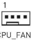
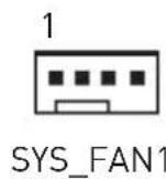
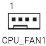
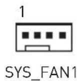
CPU_FAN1, SYS_FAN1: Fan Connectors
Fan connectors can be classified as PWM (Pulse Width Modulation) Mode or DC Mode. PWM Mode fan connectors provide constant 12V output and adjust fan speed with speed control signal. DC Mode fan connectors control fan speed by changing voltage. When you plug a 3-pin (Non-PWM) fan to a fan connector in PWM mode, the fan speed will always maintain at 100% , which might create a lot of noise. You can follow the instruction below to adjust the fan connector to PWM or DC Mode.
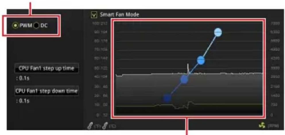
Default PWM Mode fan connectors
Default DC Mode fan connectors
You can switch between PWM mode and DC mode and adjust fan speed in BIOS > HARDWARE MONITOR.
Select PWM mode or DC mode
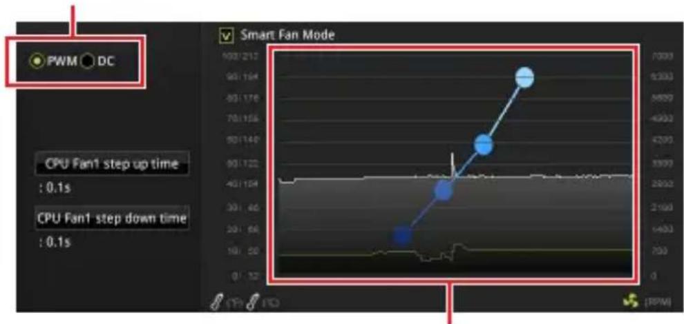
There are gradient points of the fan speed that allow you to adjust fan speed in relation to CPU temperature.

Important
Make sure fans are working properly after switching the PWM/ DC mode.
Pin definition of fan connectors
| PWM Mode pin definition | |||
| 1 | Ground 2 +12V | ||
| 3 | Sense 4 | Speed Control Signal | |
| DC Mode pin definition | |||
| 1 G | round 2 | Voltage Control | |
| 3 S | ense 4 NC | ||
EZ Debug LED
These LEDs indicate the status of the motherboard.
CPU - indicates CPU is not detected or fail.
□ DRAM - indicates DRAM is not detected or fail.
VGA - indicates GPU is not detected or fail.
- BOOT - indicates booting device is not detected or fail.
JCl1: Chassis Intrusion Connector
This connector allows you to connect the chassis intrusion switch cable.

Normal (default)

Trigger the chassis intrusion event
Using chassis intrusion detector
- Connect the JCI1 connector to the chassis intrusion switch/ sensor on the chassis.
- Close the chassis cover.
- Go to BIOS > Security > Chassis Intrusion Configuration.
- Set Chassis Intrusion to Enabled.
- Press F10 to save and exit and then press the Enter key to select Yes.
- Once the chassis cover is opened again, a warning message will be displayed on screen when the computer is turned on.
Resetting the chassis intrusion warning
- Go to BIOS > Security > Chassis Intrusion Configuration.
- Set Chassis Intrusion to Reset.
- Press F10 to save and exit and then press the Enter key to select Yes.
JBAT1: Clear CMOS (Reset BIOS) Jumper
There is CMOS memory onboard that is external powered from a battery located on the motherboard to save system configuration data. If you want to clear the system configuration, set the jumpers to clear the CMOS memory.

Keep Data [default]

Clear CMOS/ Reset BIOS
Resetting BIOS to default values
- Power off the computer and unplug the power cord
- Use a jumper cap to short JBAT1 for about 5-10 seconds.
- Remove the jumper cap from JBAT1.
- Plug the power cord and power on the computer.
BIOS Setup
The default settings offer the optimal performance for system stability in normal conditions. You should always keep the default settings to avoid possible system damage or failure booting unless you are familiar with BIOS.

Important
BIOS items are continuously update for better system performance. Therefore, the description may be slightly different from the latest BIOS and should be for reference only. You could also refer to the HELP information panel for BIOS item description.
The pictures in this chapter are for reference only and may vary from the product you purchased.
Entering BIOS Setup
Please refer the following methods to enter BIOS setup.
- Press Delete key, when the Press DEL key to enter Setup Menu, F11 to enter Boot Menu message appears on the screen during the boot process.
- Use MSI FAST BOOT application. Click on GO2BIOS button and choose OK. The system will reboot and enter BIOS setup directly.
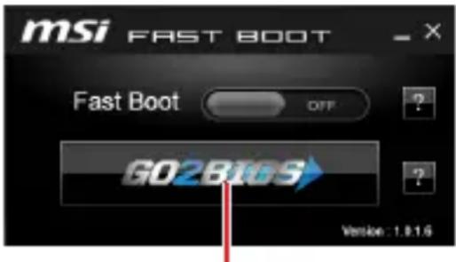
Click on GO2BIOS
Function key
F1: General Help
F2: Add/ Remove a favorite item
F3: Enter Favorites menu
F4: Enter CPU Specifications menu
F5: Enter Memory-Z menu
F6: Load optimized defaults
F7: Switch between Advanced mode and EZ mode
F8: Load Overclocking Profile
F9: Save Overclocking Profile
F10: Save Change and Reset*
F12: Take a screenshot and save it to USB flash drive (FAT/ FAT32 format only).
Ctrl+F: Enter Search page
- When you press F10, a confirmation window appears and it provides the modification information. Select between Yes or No to confirm your choice.
Resetting BIOS
You might need to restore the default BIOS setting to solve certain problems. There are several ways to reset BIOS:
- Go to BIOS and press F6 to load optimized defaults.
- Short the Clear CMOS jumper on the motherboard.

Important
Be sure the computer is off before clearing CMOS data. Please refer to the Clear CMOS jumper section for resetting BIOS.
Updating BIOS
Updating BIOS with M-FLASH
Before updating:
Please download the latest BIOS file that matches your motherboard model from MSI website. And then save the BIOS file into the USB flash drive.
Updating BIOS:
- Press Del key to enter the BIOS Setup during POST.
- Insert the USB flash drive that contains the update file into the computer.
- Select the M-FLASH tab and click on Yes to reboot the system and enter the flash mode.
- Select a BIOS file to perform the BIOS update process.
- After the flashing process is 100% completed, the system will reboot automatically.
Updating the BIOS with Live Update 6
Before updating:
Make sure the LAN driver is already installed and the Internet connection is set properly.
Updating BIOS:
- Install and launch MSI LIVE UPDATE 6.
- Select BIOS Update.
- Click on Scan button.
- Click on Download icon to download and install the latest BIOS file.
- Click Next and choose In Windows mode. And then click Next and Start to start updating BIOS.
- After the flashing process is 100% completed, the system will restart automatically.
Software Description
Installing Windows® 10
- Power on the computer.
- Insert the Windows ^假 10 disc into your optical drive.
- Press the Restart button on the computer case.
- Press F11 key during the computer POST (Power-On Self Test) to get into Boot Menu.
- Select your optical drive from the Boot Menu.
- Press any key when screen shows Press any key to boot from CD or DVD... message.
- Follow the instructions on the screen to install Windows® 10.
Installing Drivers
- Start up your computer in Windows® 10.
- Insert MSI Driver Disc into your optical drive.
- The installer will automatically appear and it will find and list all necessary drivers.
- Click Install button.
- The software installation will then be in progress, after it has finished it will prompt you to restart.
- Click OK button to finish.
- Restart your computer.
Installing Utilities
Before you install utilities, you must complete drivers installation.
- Insert MSI Driver Disc into your optical drive.
- The installer will automatically appear.
- Click Utilities tab.
- Select the utilities you want to install.
- Click Install button.
- The utilities installation will then be in progress, after it has finished it will prompt you to restart.
- Click OK button to finish.
- Restart your computer.
NOTE
AraeWoHaiMeMoRlMoTHeDIMM 5


中
SsTt 1
自
usts Maoril 4GB hre ene moi uo stn rto inhe 32-10 (Windows OS) Iha ra n t to yohhhy. d aer an bde on 4GB01st moi ro selchahrre 64-10 Windows OSu e h t o qanl .
PCI_E1~3: PCIe 應當當 0

PCI_E1: PCIe 3.0 x16 (CPU 螺钉)

PCI_E2:PCIe 2.0 x1 (PCHen)

PCI_E3:PCIe 2.0 x1 (PCHR)

中
| 1 JFP2 | 1 S | speaker - 2 Buzzer + | ||
| 3 | Buzzer - | 4 S | speaker + |
SATA1~4: SATA 6Gb/s 胎儿
Ie 6Gb/s Ie Tte Hs foetl.


中
SATAKIII90DIOLORJKTMAJI.其LGEU,前G中DEHITGAS
| 10 11 1 20 | 1 Power 11 USB2.0+ | ||
| 2 USB3_RX_DN 12 USB2.0- | |||
| 3 USB3_RX_DP 13 Ground | |||
| 4 Ground 14 USB3_TX_C_DP | |||
| 5 USB3_TX_C_DP 15 USB3_TX_C_DP | |||
| 6 USB3_TX_C_DP 16 Ground | |||
| 7 Ground 17 USB3_RX_DP | |||
| 8 USB2.0- 18 USB3_RX_DP | |||
| 9 USB2.0+ 19 | Power | ||
| 10 NC 20 No Pin | |||

中
前元贝其拉运德开到定有如
JAUD1: 朝通 ODIO 装饰部
iKuikTeTto sUoHae Tneon Pnne f 1s oDIO Oe to engelal Su htni.
| 2 10 1 9 | 1 MIC L 2 Ground | ||
| 3 MIC R 4 NC | |||
| 5 Head Phone R 6 MIC Detection | |||
| 7 SENSE_SEND 8 No Pin | |||
| 9 Head Phone L 10 Head Phone Detection |
JCOM1: 人
此用,
| 2 10 1 9 | 1 DCD 2 SIN | ||
| 3 SOUT 4 DTR | |||
| 5 | Ground | 6 D$R | |
| 7 | RTS | 8 CTS | |
| 9 RI | 10 No Pin |
JTPM1:TPM모름 기재지
I TPM(Trusted Platform Module)e engelindnla. Jeeh h nong and s uong be TPM
| 2 14 1 13 | 1 | LPC Clock 2 3V Standby power | |
| 3 LPC Reset 4 3.3V Power | |||
| 5 | LPC address & data pin0 | 6 Serial IRQ | |
| 7 | LPC address & data pin1 | 8 5V Power | |
| 9 | LPC address & data pin2 | 10 No Pin | |
| 11 | LPC address & data pin3 | 12 Ground | |
| 13 | LPC Frame | 14 Ground | |
CPU_FAN1, SYS_FAN1: 機封装电路
PWM MoD Paner 12V of 1987 h 100%
PWM 03D 按住屏幕
DC MoD 按“OK”键,打开“封装器”工具箱。
回马隆正转头向上,正定
PWM MoD3 wD DC MoD sAHI eH h BIOs > Hardware Monitor(haTweer
MoNTE]ro iEeohy Pn TnOto oEh aH.
PWM MoD 且不 DC MoD 且不
CPU运上都如拉,平头数为,自定能,能

PWM/DC 2013年版
範貢難托印
| PWM모드PIO规格的 | |||
| 1 | Ground 2+12V | ||
| 3 | Sense 4 | Speed Control Signal | |
| DC모드PIO规格的 | |||
| 1 Gound 2 | Voltage Control | ||
| 3 Sense 4 NC | |||
EZiHTGLED
LED是MéInBrod的SlateRtoFsiHniD.
CPU-CPUa
□DRAM-DRAM0I加密到自加密信期
VGA-GPU加密器
BOT-本贴当如加时自
JCI1: 生成临时封装器
iKnEeTae Ssi KIeHJt KieBt e HsHt

表珍
[基本整定]

新日
三
新社刊登时志
F8: OoRcLorKgI FOrLoPaIe RoDzHaI
F9: OoRcLorKgIeRrOaIeJrAog
F10: 质量状态及质量状态
| 1 JFP2 | 1 | Speaker - 2 | Buzzer + | |
| 3 | Buzzer - | 4 S | speaker + |
| 10 11 1 20 | 1 Power 11 USB2.0+ | ||
| 2 | USB3_RX_DN | 12 | |
| 3 | USB3_RX_DP | 13 Ground | |
| 4 | Ground 14 | USB3_TX_C_DP | |
| 5 | USB3_TX_C_DP | 15 | |
| 6 | USB3_TX_C_DP | 16 Ground | |
| 7 | Ground 17 | USB3_RX_DP | |
| 8 USB2.0-18 USB3_RX_DN | |||
| 9 | USB2.0+ 19 | ||
| 10 NC 20 No Pin | |||

Important
| 2 10 1 9 | 1 MIC L 2 Ground | ||
| 3 MIC R 4 NC | |||
| 5 Head Phone R 6 MIC Detection | |||
| 7 SENSE_SEND 8 No Pin | |||
| 9 Head Phone L 10 Head Phone Detection |
JFP1, JFP2: Frontpanel-Anschlüsse 10
SATA1-4: SATA 6Gb/s Anschlisse 10
JFP1, JFP2: Frontpanel-Anschlüsse
| 1 JFP2 | 1 | Speaker - 2 | Buzzer + | |
| 3 | Buzzer - | 4 S | speaker + |
SATA1~4: SATA 6Gb/s Anschlüsse
| 10 11 1 20 | 1 Power 11 USB2.0+ | ||
| 2 USB3_RX_DN 12 USB2.0- | |||
| 3 USB3_RX_DP 13 Ground | |||
| 4 Ground 14 USB3_TX_C_DP | |||
| 5 USB3_TX_C_DP 15 USB3_TX_C_DP | |||
| 6 USB3_TX_C_DP 16 Ground | |||
| 7 Ground 17 USB3_RX_DP | |||
| 8 USB2.0- 18 USB3_RX_DP | |||
| 9 USB2.0+ 19 | Power | ||
| 10 NC 20 No Pin | |||

Wichtig
| 2 10 1 9 | 1 MIC L 2 Ground | ||
| 3 MIC R 4 NC | |||
| 5 Head Phone R 6 MIC Detection | |||
| 7 SENSE_SEND 8 No Pin | |||
| 9 Head Phone L 10 Head Phone Detection |
KomnoheHbMaTePnHcKoI PnaTbI 7
Ipoceccopnbicoket. 8
CnotbDIMM 9
PCI_E1~3: CnoTbI paCunpeHnPa PCIe 9
JFP1, JFP2: Pa3bembl nepednei nanei 10
SATA1-4:Pa3beMbI SATA 6Γ6/c. 10
M2_1:Pa3bem M.2 (Klou M) 11
ATX_PWR1, CPU_PWR1: Pa3bembl 3JIeKTpOpiTuHaHn. 11
JUSB1:Pa3beM USB 2.0. 12
JUSB2:Pa3beM USB 3.1 Gen1 12
JAUD1:Pa3bem aydno nepednei naHei 13
JCOM1:Pa3bem nocJeobaTeIbHoro nopTa. 13
JTPM1:Pa3bem moyra TPM. 13
CPU_FAN1, SYS_FAN1: Pa3bembl BeHTnJIaTOpOB 14
HndkaTopbIOIaKnEz. 15
JCI1:Pa3bEm daTunka OTKpbITnK Kopnyca 16
UcTaHOBKa yTnIInT. 19
- Ipeed BkIIOueHnEM KOMNbIOTepa y6eINTEcb, qTO BCE BNHTbIKpePJIeHnI n DpyrHe MeTaNueckne KOMNOHEtbl Ha MaTePNHCKO INaTe N BHyTpN KOpNyCa HAdEJKHO 3aΦNKcnpOBaHbl.
He BkIouaIte KOMnbIoTe, ecn c6Opka He 3aBepweHa. 3To MoKet npNBecTN K NOBpeKdEHNIO KOMNoHErTOB, a TaKke TpaBMIpOBaHIO Nolb3OBaTeJIa.
- Ecnn Bam HyxHa NOMOuHa IIO6oM 3Tane c6opKn KOMnbIOTepa, NOxKaIyIcTa, O6paTntecb K cepTnΦuNpuOBaHHOMy KOMNbIOTepHOMy CneuaJIInCTy.
Bcerda BbIKIouaTe nHTaHne IOTcoeHNrTe shHyp nHTaHnO TJIeKTPnuecko Po3eTKn nepey yCTAHOBKO nn ydaJeHHem JIO6Oro KOMnoHETa KOMnbTOtepa.
- CoxpaHnte 3TO pyKOBODCTBO dIa CnpaBKn.
He onyckaIte Bo3deIcTBnHa MaTePunHcayIO PnA Ty BbICOKO BlaXHOCTN.
- Ipeed Tem KaK NOdKIOHHTb 6LOK NITaHnK KOMNbIOTepa K 3JIeKTpUYeCKoIPO3eTKe y6eINTEcB, YTO HApRJaEHe 3JIeKTpOceTn COOTBeTCTByETHaPraJKeHNU, yKa3aHHOMy Ha 6I0ke NITaHnI.
Pacnojarate Whyp nHTaHn TaK, YTO6bHa HrO He MoTIn HaCTyNTb IIOu. He cTabBe Ha Whyp nHTaHn HnKaKnx PpeDMetOB.
Heo6xOIMO yuNTbIbTaB BCE npedocTepeKeHn I npedynpexDeHn, yka3aHHbIe Ha MaTePNHcKoI PNaTe.
-
Pnp BO3HnKHOBeHHn IIO60n H3 nepeuNCleHHbIX HnKe cHTyaCnO6paTntEcB B cepBnCHbI ZeHTp DnI npOBepKn MaTePNHcKo NlaTbI:
-
Пonaданце КИДКОСТи BHyTpь KOMпьЮТepа.
MaTePnHcKa nlaTa noBBeprIacb Bo3deJCTBnO BnaRn.
MaTePnHcKa nIaTa He pa6oTaet OJXHbIM 06pa3OM NIN HeBO3MOxHO HanaTbe pa6O TY B COOTBeTCTBUN C pyKOBoDCTBOM NOIb3OBaTeJI. - Matepнckaj nlaTaNolyuHaNoBpeKdEHN npn naDeHn.
- Matepнская плata ямeelяВьie пиЗнй NOВpeжденя.
He xpaHnte MaTePNHckyo PnAty B MeCtax C TempeaTpyoB BbIe 60 ^ C (140 F), TaK KaK 3TO MoKeT npNBecTu K ee NOBpeXdEHNIO.
TexHnueckne xapaKTepeNCTnKN
KoMNoHcTbI MaTePnHcKoI PlaTbI
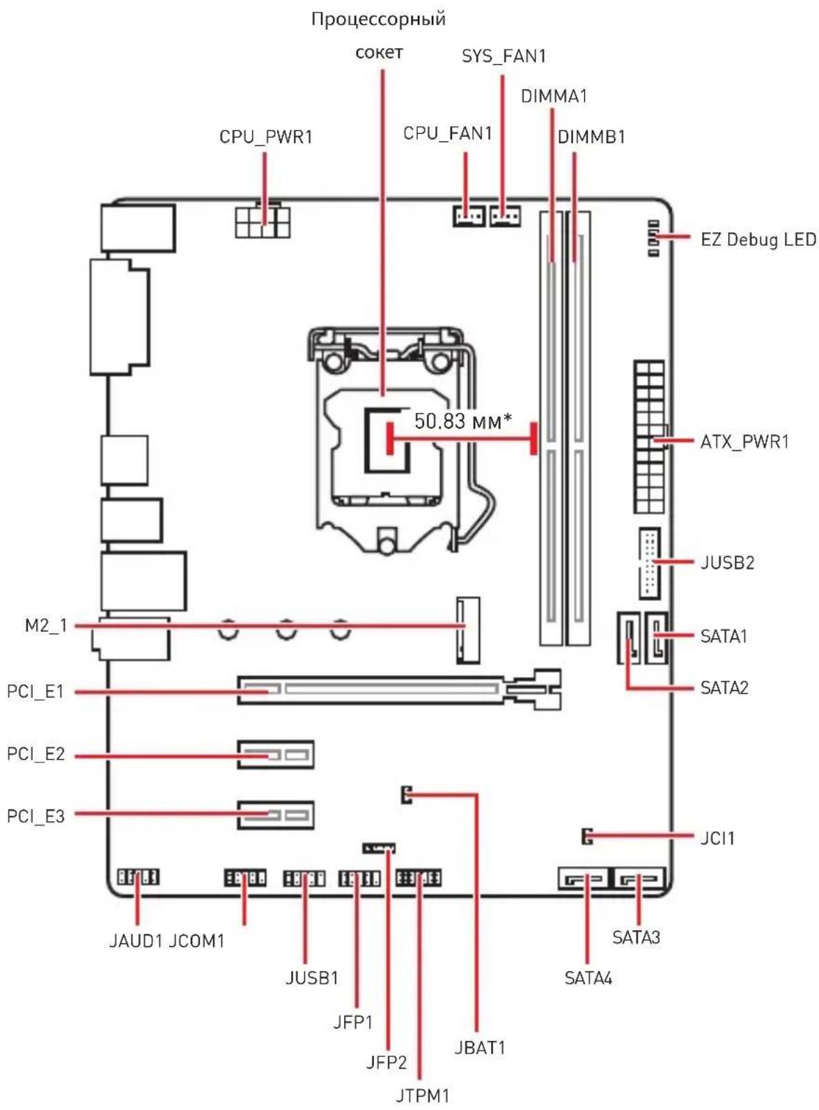
* PacctoHne ot ceHTpa npocccopa do 6nXaIwero cnoTa DIMM.
Празецсорный сокет
IoxaJyncTa, yCTaHOBnTe npoecCOp B npoecCOpHbI COKeT, KaK noka3aHo Hxke.

BHMaHne!
IpeyctaHOBKOINII3ameHOnIPOeCCopa,Heo6xOJIMOOTKIOHTb Ka6enPiTuHa.
NoxanyuNCTa, CoXpaHnTe 3aunTHyK KpbIshky npoceccophoro coketa nocne yctahOBKn npoecoppa. IIObIe BO3MOxHbIe rapaHTnHbIe Cnyau, CBra3aHHbIe c pa60ToM MaTePNHcKo PnAbl, MSl BydET paccMaTpPbBaTb TOnbKO, npu HAnuyn 3aunTHoN KpbIshKn Ha npoceccophom cokete.
Ipn yctaHOBKe npoueccopa o63aTeNbHO yCTaHOBnTe npoueCCOPbIK Kynep. Kynep, npedcTabnauoun co6oN cnCTemy oxnaJdEHHn npoueCCopa, npedynpexkaet neperpeB n obecneuBaET ctabnbHyO pa60Ty cnCTembl.
IpeBnKIIoueHHeM CnCTEmbl IpOBepbTe repMeTuHOCb CoeHHeHm Mekdy npouecccopom n paHaTopoM.
Nepereb MoKet npBecTu K cepBe3Homy NOBpeJdeHIO npOeccopa IMatepuncko nnatb. Bcerda npOBepaTe pa6OTocnOC6HocTb BeHTnIaTopa dna 3auNTbI npOeCCopa OT nepereBa. Ppr yCTaHOBKe KyIepa HaHeCnTe pOBhIn cNoi Tepmonactb [nn TepMOJeHTy] Ha KpbIshky UcTaHOBneHHoro npOeCCopa dny uLyUweHra TeTTnonepedaun.
Ecn npoueccop He yctaHOBneH, Bcerda 3aunuae Te KOHTaKTbI npoueccoPHoro COKeta NlaactNKOBOn KpbuKoN.
EcnBb npno6peHn OTdIbHo npoceccop n npoceccopHbKyIep, IpoIPO6Hoe OncsAHne yCTaHOBKn CM. B DOkymeHTaCnB DaHHOMy Kynepy.
CnotbIDIMM
IoxaJyNCTa,yctaHObnteMoynb namrtnBcNOT DIMM,kaKnoka3aHo Hxke.

BHMaHne!
Bcerda yctaHaBnBaIte MoyIb namrtn Chauana B Cnot DIMMA1.
B CBA3N CO CNEUΦIKO INCNOJIb3OBaHnpeCyPCOB YINCeTa,DOCTyNHbI O6bEm NaMAtN 6yTeT HeMHOrO MeHbWe, Yem ΦaKTNUeCKN yCTaHOBJEHbI.
IoxaynuCTa, 6bpatne BHMnHne Ha To, yTo MaKcMaJIbHa eMKoCTb aIpcyeMo namTu nn 32-6nt OC Windows, coCTabnEe He 60onee 47. EcnBbl XOTnte uCNOJb3ObaTb 60onee 475 onepaTHBOHn namTu Ha MaTePNHCKOn Pnate, peKOMeHnyETcYctaHaBnBaTb 64-6nt OC Windows.
| 10 11 1 20 | 1 Power 11 USB2.0+ | |||
| 2 USB3_RX_DN 12 USB2.0- | ||||
| 3 USB3_RX_DP 13 Ground | ||||
| 4 Ground 14 USB3_TX_C_DP | ||||
| 5 USB3_TX_C_DP 15 | USB3_TX_C_DP | |||
| 6 | USB3_TX_C_DP 16 | Ground | ||
| 7 Ground 17 | USB3_RX_DP | |||
| 8 USB2.0- 18 USB3_RX_DP | ||||
| 9 | USB2.0+ | 19 | Power | |
| 10 | NC | 20 No Pin |

BHHMaHne!
IOMHnTe, uTo BO n36eXaHne NOBpeXeHn, Heo6xOJMo IpaBnIbHO IOdkJIouaTb KOHTaKTbI NITaHnI 3eMJI.
JAUD1: Pa3bem aydno nepednei pahei
Данны разьем педназ nauseен Дя подкючени щдиоразьемов пeredneпанели.
| 2 10 1 9 | 1 MIC L 2 Ground | ||
| 3 MIC R 4 NC | |||
| 5 Head Phone R 6 MIC Detection | |||
| 7 SENSE_SEND 8 No Pin | |||
| 9 Head Phone L 10 Head Phone Detection |
JCOM1: Pa3bem nocledoBaTeIbHoro nopTa
JaHHbI pa3bem N03BOJareT NOKJIQUHTb NocJeIOBaTeJIbHbI NOPr, pa3MeueHHbI Ha BHeuHem 6peKeTe.
| 2 10 1 9 | 1 DCD 2 SIN | |||
| 3 SOUT 4 DTR | ||||
| 5 | Ground | 6 | DSR | |
| 7 | RTS | 8 | CTS | |
| 9 RI | 10 No Pin |
JTPM1: Pa3bem moулг TPM
HdNKaTopbI OTlaKn EZ
IaHHbIe CBeToIDNoDbI NOKa3bIBaIOT COCTOHNMaTePHNckO nnate.
CPU - npoceccop He o6napxkeH nll noBpeKdEh.
DRAM -памятб DRAM He обаружени поврждана.
VGA-BndeokapTa He o6napxkeHa nn nobpejdeHa.
BOT-yctpoiCTBO3aIpy3KnHeo6napyKeHOnnnnoBpeJdeHo.
JCI1: Pa3bem daTUnka OTKpbITnK Kopnyca
Kətomy pa3bemy nodklouaetcKa6eIb ot daTUnka OTkpBITnKopnyca.

HopmaIbHo (No ymoJauHaHIO)
Pa3peuNTb 3aNNcB no co6bITnO OTKpbTna Kopnyca
IcnoIb3OBAHne daTUnka OTKpbITnKopnyca
- Подклочи Te рдклочи DeatчнК OTkpbltna K pa3bemy JCI1.
- 3aKpoIte KpbIshKy Kopnyca.
- BovДиTeВBIOS>Security>Chassis Intrusion Configuration.
- YCTaHOBtE Chassis Intrusion B Enabled.
- HaxmTe KlaBnuy F10, TTo6bI coXpaHnTb HaCTpoN N BblTN, a 3aTe M HaxmTe KlaBnuy Enter, TTo6bI Bbl6paTb Yes.
- Пи OTкрытей Корпуca Ha ḋкране ьдгпляТьсг пpeурждюшee cooшцене кждь pa3 ри Вклioчehnн KOMпьЮтepa.
C6poc coo6eHn o6 otKpbTn KOpnyca
- BovienTEBBIOS >Security>Chassis Intrusion Configuration.
- BbI6epuTe Chassis Intrusion, Reset.
- HaxMMTe KlaBnuy F10, yTo6bl coXpaHnTb HacTpOuKN N BblNTN, a 3aTEM HaxMMTe KlaBnuy Enter, yTo6bl Bbl6paTb Yes.
F3: BxOД B MeHIO I36paHHoe
F4: BxOД B MeHо TexHnuecknX napaMeTpOB npoceccopa
F5: BxOД B MeHIO Memory-Z
F6: 3arpy3ntb onTmMn3npoBaHbIe HaCTpoiKn no ymoJauHIO
F7: IpepeKJIIOUHTb MeKdY paCShIpeHHOM peXIMOM n peXIMOM EZ
F8: 3arpy3ntb npoΦnIb pa3roHa
F9: CoxpaHnTb npoΦnIb pa3roHa
F10: CoxpaHntb n3MeHeHn i nepe3aRpy3NTb*
F12: CdeNaTb cKpHnWOT n coXpaHnTb ero Ha USB fJ3w-dnck (ToIbKO FAT/ FAT32 fOpMaT).
Ctrl+F:BxOДВCTpaHnUyNONCKa
*Pn HaxaTnn KlaBnIe F10 NOABNTcN HOpMaunOHoe OKHO. Bb6epnte Yes nn No, TTo6bl NpTBePdntb Bb6op.
C6poc BIOS
B HeKOTopbIX cIyauqnx Heo6xOJHmO BblONHnTb BOCCTaHOBneHne HacTpoeK
BIOS do 3naueHn no yMOnuAHnIO. CyueCTByeT HeckoJIbKO cnocO6OB c6poca
HaCtpoek:
BoiTe BBIOS n HaxMnte KnaBnSy F6 3arpy3Kn ONTmN3npoBaHHbIX 3HaueHn NO yMOJuaHnIO.
3aMKHnTe Jxamnep Clear CMOS Ha MaTepuHcko nlaTe.

BHHMaHHe!
y6eHTecb, yTO KOMNbIOTep BblKnIOueH nepei OuNCTKo JaHHbIX CMOS. IJIa NOUYehn DaONOHInTeBHO INHΦOpMaun O c6poce HacTpoek BIOS, 6paTntecb K pa3dEny "JkaMnep OUNCKn DaHHbIX CMOS".
06HOBJIeHneBIOS
06HOBJIeHHeBIOSpNI pIOMoU M-FLASH
IoproToBnteNbHbIe onepaun:
Noxanynta,ckaayTe nocnHIOBepcno paINa B1OS ccaT a MSl,koTobio COOTBeTCTByeT BaWeMdoJI MaTePunHcKo INaTbI. CoXpaHnte paIb BIOS Ha 13w-dncke USB.
06HOBJIeHneBIOS:
- Haxmte KnaBnuy Del nla BxOda B HacTroKn BIOS BO BpeM npoceDpyb
- BCTaBbTe Φιλη-ДИСК USB, coDEpKaUπ Φaɪn 06HOBJIeHЯВ KOMNbIbIeP
- BbI6epnTe BknaKy M-FLASH n HaKmTe Ha KHOIp Ky Yes npe3arpy3Kn CnCTembln BXOda B peKIM O6HOBJIeHHa.
- Bb6epnte faIBIOS IyBbIOJIHeHnI pOceCa 6HOBJeHnBIOS.
- После заBERшеня поцета оьновеленя, систema nepe3arpy3ntcra botOMaTnyeCKN
06HOBJIeHneBIOSpni pnoosnLive Update 6
Ipeo6HOBlenHnem:
Y6eINTEcB, YTO dpaBep IokaIbHOJ cETn yCTaHOBHeH n eCTb NOKJIuOHeHne K cETn INHTepHET.
06HOBJIeHneBIOS:
- YctaHOBIne n 3anyCTnTe MSI LIVE UPDATE 6.
- BbI6epuTe BIOS Update.
- HaxMMTe Ha KONky Scan.
- Haxmte Ha 3HaOK Download, yTo6bI 3aIpy3nTb n yCTaHOBnTb IocJeHIO Bepcno faiJa BIOS.
- HaxMMTe KhoNky Next In Windows mode. 3aTeM HaxMMTe KhoNky Next n Start 3anycka o6HOBnHnB BIOS.
- 10 3aBepseHIO npoceca o6HOBlenn, cncTeMa nepe3arpy3ntcA bTOMaTnueckn.
| 10 11 1 20 | 1 Power 11 USB2.0+ | ||
| 2 USB3_RX_DN 12 USB2.0- | |||
| 3 USB3_RX_DP 13 Ground | |||
| 4 Ground 14 USB3_TX_C_DP | |||
| 5 USB3_TX_C_DP 15 USB3_TX_C_DP | |||
| 6 USB3_TX_C_DP 16 Ground | |||
| 7 Ground 17 USB3_RX_DP | |||
| 8 USB2.0- 18 USB3_RX_DP | |||
| 9 | USB2.0+ | 19 Power | |
| 10 | NC | 20 No Pin |

注意
| 2 10 1 9 | 1 MIC L 2 Ground | ||
| 3 MIC R 4 NC | |||
| 5 Head Phone R 6 MIC Detection | |||
| 7 SENSE_SEND 8 No Pin | |||
| 9 Head Phone L 10 Head Phone Detection |
JCOM1: 串行端头接口
此接口允许您连接可选串行端口可用插槽。
| 2 10 1 9 | 1 DCD 2 SIN | |||
| 3 SOUT 4 DTR | ||||
| 5 | Ground | 6 | DSR | |
| 7 | RTS | 8 | CTS | |
| 9 RI | 10 No Pin |
JTPM1: TPM模组接口
| 10 11 1 20 | 1 Power 11 USB2.0+ | ||
| 2 USB3_RX_DN 12 USB2.0- | |||
| 3 USB3_RX_DP 13 Ground | |||
| 4 Ground 14 USB3_TX_C_DP | |||
| 5 USB3_TX_C_DP 15 | USB3_TX_C_DP | ||
| 6 | USB3_TX_C_DP 16 | Ground | |
| 7 Ground 17 | USB3_RX_DP | ||
| 8 USB2.0- 18 USB3_RX_DP | |||
| 9 | USB2.0+ | 19 Power | |
| 10 | NC | 20 No Pin |

重要
| 2 10 1 9 | 1 MIC L 2 Ground | ||
| 3 MIC R 4 NC | |||
| 5 Head Phone R 6 MIC Detection | |||
| 7 SENSE_SEND 8 No Pin | |||
| 9 Head Phone L 10 Head Phone Detection |
JCOM1: 序列埠接頭
此接頭用來連接選擇性配置的序列埠托架。
| 2 10 1 9 | 1 DCD 2 SIN | |||
| 3 SOUT 4 DTR | ||||
| 5 | Ground | 6 | DSR | |
| 7 | RTS | 8 | CTS | |
| 9 RI | 10 No Pin |
JTPM1: TPM 模組接頭
PCI_E2:PCIe 2.0× 1 (PCHL

PCI_E3:PCIe 2.0× 1 (PCHLEON)

注意
| 1 JFP2 | 1 | Speaker - | 2 | Buzzer + |
| 3 | Buzzer - | 4 S | speaker + |
SATA1~4: SATA 6Gb/sコネケ一
| 10 11 1 20 | 1 Power 11 USB2.0+ | ||
| 2 USB3_RX_DN 12 USB2.0- | |||
| 3 USB3_RX_DP 13 Ground | |||
| 4 Ground 14 USB3_TX_C_DP | |||
| 5 USB3_TX_C_DP | 15 | USB3_TX_C_DP | |
| 6 USB3_TX_C_DP | 16 | Ground | |
| 7 Ground 17 USB3_RX_DP | |||
| 8 USB2.0- 18 USB3_RX_DP | |||
| 9 USB2.0+ | 19 | Power | |
| 10 NC | 20 | No Pin |

注意
| 2 10 1 9 | 1 MIC L 2 Ground | ||
| 3 MIC R 4 NC | |||
| 5 Head Phone R 6 MIC Detection | |||
| 7 SENSE_SEND 8 No Pin | |||
| 9 Head Phone L 10 Head Phone Detection |
JCOM1: プーネトコネケタ
FCC Compliance Statement
Note: This equipment has been tested and found to comply with the limits for a Class B digital device, pursuant to part 15 of the FCC Rules. These limits are designed to provide reasonable protection against harmful interference in a residential installation. This equipment generates, uses and can radiate radio frequency energy and, if not installed and used in accordance with the instructions, may cause harmful interference to radio communications. However, there is no guarantee that interference will not occur in a particular installation. If this equipment does cause harmful interference to radio or television reception, which can be determined by turning the equipment off and on, the user is encouraged to try to correct the interference by one or more of the following measures:
Reorient or relocate the receiving antenna.
- Increase the separation between the equipment and receiver.
- Connect the equipment into an outlet on a circuit different from that to which the receiver is connected.
- Consult the dealer or an experienced radio/TV technician for help.
Caution: Changes or modifications not expressly approved by the party responsible for compliance could void the user's authority to operate the equipment.

Tested to comply with FCC standards FOR HOME OR OFFICE USE
This device complies with part 15 of the FCC Rules. Operation is subject to the following two conditions:
[1] This device may not cause harmful interference, and [2] this device must accept any interference received, including interference that may cause undesired operation.
CE Conformity

Hereby, Micro-Star International CO., LTD declares that this device is in compliance with the essential safety
requirements and other relevant provisions set out in the European Directive.
C-Tick Compliance

N1996
Bkgjg (aegngbngs

i i
クラスB情報技術裝置

Batteries, battery packs, and accumulators should not be disposed of as unsorted household waste. Please use the public collection system to return, recycle, or treat them in compliance with the
local regulations.
Taiwan:

廢電池請回收
For better environmental protection, waste batteries should be collected separately for recycling or special disposal.
California, USA:

The button cell battery may contain perchlorate material and requires special handling when recycled or disposed of in California.
For further information please visit:
http://www.dtsc.ca.gov/hazardouswaste/perchlorate/
CAUTION: There is a risk of explosion, if battery is incorrectly replaced.
Replace only with the same or equivalent type recommended by the manufacturer.
Chemical Substances Information
In compliance with chemical substances regulations, such as the EU REACH Regulation (Regulation EC No. 1907/2006 of the European Parliament and the Council), MSI provides the information of chemical substances in products at:
http://www.msi.com/html/popup/csr/evmtprtt_
pcm.html
WEEE (Waste Electrical and Electronic Equipment) Statement
ENGLISH
To protect the global environment and as an environmentalist, MSI must remind you that... Under the European Union ("EU") Directive on Waste Electrical and Electronic Equipment, Directive 2002/96/EC, which takes effect on August 13, 2005, products of "electrical and electronic equipment" cannot be discarded as municipal wastes anymore, and manufacturers of covered electronic equipment will be obligated to take back such products at the end of their useful life. MSI will comply with the product take back requirements at the end of life of MSI-branded products that are sold into the EU. You can return these products to local collection points.
DEUTSCH
This product complies with the "India E-waste (Management and Handling) Rule 2011" and prohibits use of lead, mercury, hexavalent chromium, polybrominated biphenyls or polybrominated diphenyl ethers in concentrations exceeding 0.1 weight % and 0.01 weight % for cadmium, except for the exemptions set in Schedule 2 of the Rule.
Environmental Policy
The product has been designed to enable proper reuse of parts and recycling and should not be thrown away at its end of life.
- Users should contact the local authorized point of collection for recycling and disposing of their end-of-life products.
- Visit the MSI website and locate a nearby distributor for further recycling information.

Users may also reach us at gpontdev@msi.com for information regarding proper Disposal, Take-back, Recycling, and Disassembly of MSI products.
产品中有害物质的名称及含量
If a problem arises with your system and no solution can be obtained from the user guide, please contact your place of purchase or local distributor. Alternatively, please try the following help resources for further guidance.
- Visit the MSI website for technical guide, BIOS updates, driver updates, and other information: http://www.msi.com
- Register your product at: http://register.msi.com
Copyright
msi Micro-Star Int' L Co.,Ltd. Copyright © 2018 All rights reserved.
The MSI logo used is a registered trademark of Micro-Star Int'l Co., Ltd. All other marks and names mentioned may be trademarks of their respective owners. No warranty as to accuracy or completeness is expressed or implied. MSI reserves the right to make changes to this document without prior notice.
Revision History
Version 2.0, 2018/02, First release. Version 2.1, 2018/05, Update PCIe spec